WO2023282282A1 - ガス測定装置 - Google Patents
ガス測定装置 Download PDFInfo
- Publication number
- WO2023282282A1 WO2023282282A1 PCT/JP2022/026807 JP2022026807W WO2023282282A1 WO 2023282282 A1 WO2023282282 A1 WO 2023282282A1 JP 2022026807 W JP2022026807 W JP 2022026807W WO 2023282282 A1 WO2023282282 A1 WO 2023282282A1
- Authority
- WO
- WIPO (PCT)
- Prior art keywords
- gas
- sample
- bubbling
- cell
- separator
- Prior art date
- Legal status (The legal status is an assumption and is not a legal conclusion. Google has not performed a legal analysis and makes no representation as to the accuracy of the status listed.)
- Ceased
Links
Images



Classifications
-
- G—PHYSICS
- G01—MEASURING; TESTING
- G01N—INVESTIGATING OR ANALYSING MATERIALS BY DETERMINING THEIR CHEMICAL OR PHYSICAL PROPERTIES
- G01N21/00—Investigating or analysing materials by the use of optical means, i.e. using sub-millimetre waves, infrared, visible or ultraviolet light
- G01N21/17—Systems in which incident light is modified in accordance with the properties of the material investigated
- G01N21/25—Colour; Spectral properties, i.e. comparison of effect of material on the light at two or more different wavelengths or wavelength bands
- G01N21/31—Investigating relative effect of material at wavelengths characteristic of specific elements or molecules, e.g. atomic absorption spectrometry
- G01N21/35—Investigating relative effect of material at wavelengths characteristic of specific elements or molecules, e.g. atomic absorption spectrometry using infrared light
- G01N21/3504—Investigating relative effect of material at wavelengths characteristic of specific elements or molecules, e.g. atomic absorption spectrometry using infrared light for analysing gases, e.g. multi-gas analysis
-
- G—PHYSICS
- G01—MEASURING; TESTING
- G01N—INVESTIGATING OR ANALYSING MATERIALS BY DETERMINING THEIR CHEMICAL OR PHYSICAL PROPERTIES
- G01N1/00—Sampling; Preparing specimens for investigation
- G01N1/02—Devices for withdrawing samples
- G01N1/22—Devices for withdrawing samples in the gaseous state
- G01N1/2247—Sampling from a flowing stream of gas
-
- G—PHYSICS
- G01—MEASURING; TESTING
- G01N—INVESTIGATING OR ANALYSING MATERIALS BY DETERMINING THEIR CHEMICAL OR PHYSICAL PROPERTIES
- G01N33/00—Investigating or analysing materials by specific methods not covered by groups G01N1/00 - G01N31/00
- G01N33/0004—Gaseous mixtures, e.g. polluted air
- G01N33/0009—General constructional details of gas analysers, e.g. portable test equipment
-
- G—PHYSICS
- G01—MEASURING; TESTING
- G01N—INVESTIGATING OR ANALYSING MATERIALS BY DETERMINING THEIR CHEMICAL OR PHYSICAL PROPERTIES
- G01N33/00—Investigating or analysing materials by specific methods not covered by groups G01N1/00 - G01N31/00
- G01N33/0004—Gaseous mixtures, e.g. polluted air
- G01N33/0009—General constructional details of gas analysers, e.g. portable test equipment
- G01N33/0027—General constructional details of gas analysers, e.g. portable test equipment concerning the detector
- G01N33/0036—General constructional details of gas analysers, e.g. portable test equipment concerning the detector specially adapted to detect a particular component
- G01N33/0037—NOx
-
- G—PHYSICS
- G01—MEASURING; TESTING
- G01N—INVESTIGATING OR ANALYSING MATERIALS BY DETERMINING THEIR CHEMICAL OR PHYSICAL PROPERTIES
- G01N33/00—Investigating or analysing materials by specific methods not covered by groups G01N1/00 - G01N31/00
- G01N33/0004—Gaseous mixtures, e.g. polluted air
- G01N33/0009—General constructional details of gas analysers, e.g. portable test equipment
- G01N33/0027—General constructional details of gas analysers, e.g. portable test equipment concerning the detector
- G01N33/0036—General constructional details of gas analysers, e.g. portable test equipment concerning the detector specially adapted to detect a particular component
- G01N33/004—CO or CO2
-
- G—PHYSICS
- G01—MEASURING; TESTING
- G01N—INVESTIGATING OR ANALYSING MATERIALS BY DETERMINING THEIR CHEMICAL OR PHYSICAL PROPERTIES
- G01N33/00—Investigating or analysing materials by specific methods not covered by groups G01N1/00 - G01N31/00
- G01N33/0004—Gaseous mixtures, e.g. polluted air
- G01N33/0009—General constructional details of gas analysers, e.g. portable test equipment
- G01N33/0027—General constructional details of gas analysers, e.g. portable test equipment concerning the detector
- G01N33/0036—General constructional details of gas analysers, e.g. portable test equipment concerning the detector specially adapted to detect a particular component
- G01N33/0042—SO2 or SO3
Definitions
- the present disclosure relates to gas measuring devices.
- Patent Document 1 discloses an infrared gas analyzer that measures the concentration of gas components by switching between a sample gas and a reference gas.
- a three-way valve is switched to alternately supply the sample gas and the reference gas into the cell at predetermined intervals.
- the sector is rotated by the motor, and the infrared light from the light source is intermittently irradiated into the cell.
- the detector alternately detects the infrared light that has passed through the sample gas or the reference gas, and the gas components can be analyzed based on the output ratio between the detection output of the reference gas and the detection output of the sample gas.
- Patent Document 2 discloses a two-path gas analyzer using two cells.
- a measurement error occurs when a sample gas contains a gas component whose infrared absorption band overlaps with that of a gas component to be measured (hereinafter referred to as an interference component).
- an interference component For example, when measuring sulfur dioxide (SO2) in the flue gas, HC and CO2 are present in the flue gas as interfering components.
- Patent Document 1 Japanese Patent Application Laid-Open No. 9-49797
- Patent Document 1 can use, as a reference gas, air that does not contain SO 2 which is a component of the gas to be measured.
- the atmosphere contains almost no HC and CO2 , which are interfering components in SO2 measurement, the output of the difference in infrared absorption between the sample gas and the reference gas is the interference Ingredients can cause measurement errors.
- interference countermeasures such as installing a multi-layer optical filter that narrows the transmission wavelength band or a cell filled with a high concentration of interference gas in the optical path are also conceivable. Although this method has a certain degree of interference reduction effect, it is not sufficient in many cases, and some interference error remains. In addition, by inserting such an optical filter in the optical path, the light is attenuated, resulting in poor measurement accuracy.
- An object of the present disclosure is to provide a gas measuring device capable of improving the detection accuracy of SO 2 while suppressing development costs.
- the present disclosure relates to a gas measurement device that measures a gas component to be analyzed in a sample gas.
- the gas measurement device includes a sample gas line for dehumidifying the sample gas, a reference gas line for generating a dehumidified reference gas after removing the gas component to be analyzed from the sample gas, a sample cell, and gas passing through the reference gas line. and a first switching section for selectively supplying the sample cell with the gas that has passed through the sample gas line, a light source for irradiating the sample cell with light, and the light irradiated from the light source to the sample cell transmitted through the sample cell. a detection unit that detects light intensity.
- the gas component to be analyzed includes SO2 gas.
- the reference gas line includes a bubbling separator that removes SO2 gas from the sample gas by bubbling the sample gas with water, and a dehumidifier that dehumidifies the gas that has passed through the bubbling separator.
- the gas measuring device removes the gas to be analyzed from the sample gas with a bubbling separator to obtain a reference gas. Therefore, since the interference component gas of the same concentration exists in the reference gas, the influence of the interference component gas can be canceled.
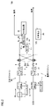
- FIG. 1 is a diagram schematically showing the configuration of a gas measuring device according to Embodiment 1; FIG. It is a figure which shows roughly the structure of the gas measuring apparatus of the example of examination.
- FIG. 4 is a diagram schematically showing the configuration of a gas measuring device of a modified example of Embodiment 1;
- FIG. 5 is a diagram schematically showing the overall configuration of a gas measuring device according to Embodiment 2;
- FIG. 4 is a diagram for explaining reading of a signal from a detector;
- FIG. 10 is a diagram schematically showing the configuration of a gas measuring device of a modified example of Embodiment 2;
- FIG. 1 is a diagram schematically showing the configuration of a gas measuring device according to Embodiment 1.
- FIG. FIG. 2 is a diagram schematically showing the configuration of the gas measurement device of the study example.
- the gas measuring device 100 in FIG. 1 differs from the gas measuring device 500 in FIG. 2 in the configuration of the reference gas line RL.
- the configuration of FIG. 1 will be described below in comparison with FIG.
- the gas measuring device 100 shown in FIG. 1 includes a sample gas line ML, a reference gas line RL, a switching section 8, and a sample cell 9.
- a sample gas M is introduced into the sample gas line ML.
- the sample gas line ML includes a drain separator 1 that separates drain water generated by natural cooling, a cooler 2 that dehumidifies the sample gas by cooling it, and a drain pot that stores the drain water separated by the drain separator 1 and the cooler 2. 7.
- the sample gas line ML further includes a filter 4 through which the sample gas M passes, a pump 5 that delivers the sample gas M, and a needle valve 6 that adjusts the flow rate of the sample gas M.
- sample gas line ML described above has the same configuration in the study example of FIG. 2 and the first embodiment of FIG.
- Embodiment 1 air is introduced into the reference gas line RL.
- the sample gas M is also introduced into the reference gas line RL.
- the reference gas line RL further includes a filter 14 through which the reference gas R passes, a pump 15 that delivers the reference gas R, and a needle valve 16 that adjusts the flow rate of the reference gas R.
- the reference gas R a gas obtained by bubbling the sample gas M with water to remove the water-soluble SO 2 is used.
- a bubbling separator 11 or the like is used for water bubbling.
- the combustion exhaust gas from a factory, an incineration plant, or the like is the sample gas M
- water bubbling can be performed by the water content of the sample gas M itself.
- the bubbling separator 11 may be replenished with water, or the bubbling separator 11 may be replenished with drain water from the cooler 2 or 12 .
- the switching unit 8 includes a three-way valve 8M arranged in the sample gas line ML and a three-way valve 8R arranged in the reference gas line RL.
- the three-way valves 8M and 8R configure flow paths so that the gas that has passed through either the reference gas line RL or the sample gas line ML is sent to the sample cell 9 and the gas that has passed through the other is exhausted according to the selection signal SEL. do.
- the gas measurement device 100 further includes a motor 19, a sector 18, a light source 10, an SO2 detector 20, and a control device 30.
- the sample cell 9 has a gas inlet 9a and a gas outlet 9b. Via the switching unit 8, the sample gas M or the reference gas R is supplied into the sample cell 9 from the gas inlet 9a and discharged from the gas outlet 9b.
- a light source 10 for emitting infrared light is provided at one end of the sample cell 9, and an SO2 detector 20 for detecting infrared light transmitted through the sample cell 9 is provided at the other end of the sample cell 9.
- a sector 18 for interrupting infrared light is provided between the light source 10 and the end of the sample cell 9 .
- This sector 18 has a light-shielding portion and a light-transmitting portion.
- the sector 18 is configured to rotate around the sector rotation axis 18e. Infrared light is irradiated into the sample cell 9 when the light-transmitting portion is above the sample cell 9, and irradiation of infrared light into the sample cell 9 is blocked when the light-shielding portion is above the sample cell 9. .
- the control device 30 controls the rotational position of the sector 18 via the motor 19, and also controls the drive of the switching unit 8 by the selection signal SEL.
- SO 2 absorbs light of a specific wavelength in the infrared region (SO 2 : 7.4 ⁇ m). Therefore, the concentration of SO2 can be measured by measuring the infrared absorption after passing through the measurement gas with the SO2 detector 20 that is sensitive only to this wavelength.
- the gas to be detected in the sample gas is sealed inside the SO2 detector 20, and the intensity of infrared light at a frequency unique to the gas to be detected is detected by internal pressure changes. Then, the controller 30, which receives the detection output of the SO2 detector 20, performs predetermined signal processing to calculate a concentration value indicating the measured gas concentration in the sample gas.
- the reference gas R does not contain the interfering components HC and CO2
- the sample gas M contains the interfering components.
- the C—H bond absorption wavelength band of 7.2 ⁇ m is close to the SO 2 absorption wavelength band of 7.4 ⁇ m. Therefore, the influence of HC causes an error in the measurement of SO2 concentration.
- the absorption wavelength band of CO2 4.3 ⁇ m is separated from the absorption wavelength band of SO2 7.4 ⁇ m
- the concentration of CO2 in the sample gas is generally significantly greater than that of SO2, so only a small Even the overlap of the absorption wavelength bands causes an error in the measurement of the SO 2 concentration because it affects as an interference component.
- the gas measuring device 100 of Embodiment 1 shown in FIG. included Therefore, the difference in infrared absorption between the sample gas M and the reference gas R cancels out the influence of the interference component. Therefore, the concentration of SO 2 can be measured without being affected by interfering components. According to Embodiment 1, even when the interference component and its concentration are unknown, the influence of the interference component can be removed at a lower cost and with higher accuracy than in the prior art.
- Embodiment 1 the gas measuring apparatus configured to alternately introduce the sample gas and the reference gas into the sample cell was shown. may apply.
- FIG. 3 is a diagram schematically showing the configuration of a gas measuring device according to a modification of Embodiment 1.
- FIG. A gas measuring device 100A shown in FIG. 3 includes a reference cell 59 instead of the switching unit 8 in the configuration of the gas measuring device 100 shown in FIG.
- Other parts of the configuration of gas measuring device 100A are the same as those of gas measuring device 100 shown in FIG. 1, and thus description thereof will not be repeated.
- the sample gas that has passed through the sample gas line ML is introduced into the sample cell 9 as it is.
- the reference cell 59 has a gas inlet 59a and a gas outlet 59b.
- the reference gas that has passed through the reference gas line RL is introduced into the reference cell 59 from the gas introduction port 59a of the reference cell 59, and then exhausted from the gas discharge port 59b.
- the SO2 detector 20 detects the difference between the intensity of infrared light that has passed through the sample cell 9 and the intensity of infrared light that has passed through the reference cell 59 .
- the infrared gas analyzer that performs measurements by switching between the sample gas and the reference gas has described the SO 2 measuring apparatus that uses the sample gas from which SO 2 has been dissolved and removed by water bubbling as the reference gas.
- the SO 2 measuring apparatus that uses the sample gas from which SO 2 has been dissolved and removed by water bubbling as the reference gas.
- a multi-component measuring device that can simultaneously measure components other than SO2 in gas measuring devices.
- the method of generating the reference gas according to Embodiment 1 is not suitable for NO, CO, and CO 2 , which are poorly soluble in water. is not removed by the bubbling separator, so it is unsuitable as a reference gas for NOx, CO, and CO2 measurements.
- a three-way valve 13 is provided downstream of the bubbling separator 11, and the gas (R1) produced by the sample gas passing through the bubbling separator 11 and the atmosphere (R2) are alternately used as the reference gas. do.
- FIG. 4 is a diagram schematically showing the overall configuration of a gas measuring device according to Embodiment 2.
- FIG. A gas measuring apparatus 200 shown in FIG. 4 has a reference gas line RLA in place of the reference gas line RL and a detection section 20A in place of the SO2 detector 20 in the configuration of the gas measuring apparatus 100 shown in FIG.
- Sample gas line ML, switching unit 8, sample cell 9, motor 19, sector 18, and light source 10 are common to gas measuring apparatus 200 and gas measuring apparatus 100, so description thereof will not be repeated.
- the reference gas line RLA shown in FIG. 4 differs from the reference gas line RL shown in FIG. 1 in that a three-way valve 13 is added between the bubbling separator 11 and cooler 12 .
- the three-way valve 13 selects either one of the reference gas R1 that has passed through the bubbling separator 11 and the reference gas R2 that is the atmosphere and sends it to the cooler 12 according to a selection signal SEL2 given from the control device 30 .
- the bubbling separator 11, the cooler 12, the drain pot 17, the filter 14, the pump 15, and the needle valve 16 are the same as those in FIG. 1, so the description will not be repeated.
- the detection unit 20A includes an SO2 detector 22, an NO detector 23, a CO detector 24, and a CO2 detector 25, which detect SO2, NO, CO, and CO2 , respectively.
- SO 2 , NO, CO, and CO 2 absorb light of specific wavelengths in the infrared region (SO 2 : 7.4 ⁇ m, NO: 5.3 ⁇ m, CO: 4.6 ⁇ m, CO 2 : 4.3 ⁇ m). do. Therefore, the concentration of each component can be measured by measuring the infrared absorption after passing through the measurement gas with a detector that is sensitive only to each of these wavelengths.
- Each detector contains the gas to be detected in the sample gas, and detects the intensity of the infrared light at the frequency specific to the gas to be detected based on internal pressure changes. Then, the controller 30, which receives the detection output from the detector 20A, performs predetermined signal processing to calculate a concentration value indicating the concentration of the measured gas in the sample gas.
- FIG. 5 is a diagram for explaining how the detector signals are read.
- a selection signal SEL is input to the switching unit 8 and a selection signal SEL2 is input to the three-way valve 13 .
- the selection signal SEL2 switches between the reference gas R1 and the reference gas R2 every 20 seconds. Also, the sample gas M and the reference gas R are switched every 10 seconds by the selection signal SEL.
- the detection signal of the reference gas R1 and the detection signal of the reference gas R2 are alternately read with the detection signal of the sample gas M interposed therebetween.
- t4 to t6, t8 to t10, . 30 performs SO2 concentration measurements.
- NO, CO, and CO2 are measured during each period of time t2-t4, t6-t8, . . .
- each of the NO detector 23, the CO detector 24, and the CO2 detector 25 outputs a detection signal of the reference gas R2 to the control device 30, and in the second half of each period, the NO detector 23, the CO detection
- Each of the detector 24 and the CO2 detector 25 outputs a detection signal of the sample gas M to the controller 30 .
- the controller 30 measures NO, CO and CO 2 concentrations based on the difference between the first half signal and the second half signal.
- Embodiment 1 With the configuration of Embodiment 1 as it is, it was not possible to configure a highly accurate multi-component meter, but in Embodiment 2, while using the interference removal technology at the time of SO 2 concentration measurement, a single measuring device Multi-component measurement becomes possible. Therefore, a low-cost multi-component analyzer including a low-interference SO 2 analyzer that requires a small installation space is possible.
- the difference between the second signal and the first signal obtained from the NO detector 23 makes it secondarily possible to measure the NO 2 concentration.
- the gas measuring device is configured to alternately introduce the sample gas and the reference gas into the sample cell. may apply.
- FIG. 6 is a diagram schematically showing the configuration of a gas measuring device according to a modification of the second embodiment.
- a gas measuring device 200A shown in FIG. 6 includes a reference cell 59 instead of the switching unit 8 in the configuration of the gas measuring device 200 shown in FIG.
- Other parts of the configuration of gas measuring device 200A are the same as those of gas measuring device 200 shown in FIG. 3, and thus description thereof will not be repeated.
- the sample gas that has passed through the sample gas line ML is introduced into the sample cell 9 as it is.
- the reference cell 59 has a gas inlet 59a and a gas outlet 59b.
- the reference gas that has passed through the reference gas line RL is introduced into the reference cell 59 from the gas introduction port 59a of the reference cell 59, and then exhausted from the gas discharge port 59b.
- the SO2 detector 20 detects the difference between the intensity of infrared light that has passed through the sample cell 9 and the intensity of infrared light that has passed through the reference cell 59 .
- the present disclosure relates to a gas measuring device that measures a gas component to be analyzed in a sample gas.
- the gas measurement device includes a sample gas line for dehumidifying the sample gas, a reference gas line for generating a dehumidified reference gas after removing the gas component to be analyzed from the sample gas, a sample cell, and gas passing through the reference gas line.
- a sample gas switching unit that selectively supplies the gas that has passed through the sample gas line to the sample cell; a light source that irradiates the sample cell with light; a detection unit that detects light intensity.
- the gas component to be analyzed includes SO2 gas.
- the reference gas line includes a bubbling separator that removes SO2 gas from the sample gas by bubbling the sample gas with water, and a dehumidifier that dehumidifies the gas that has passed through the bubbling separator.
- the gas measuring device includes a sample gas line for dehumidifying the sample gas, a reference gas line for generating a dehumidified reference gas after removing the gas component to be analyzed from the sample gas, and the gas passing through the sample gas line is introduced.
- a sample cell a reference cell into which the gas that has passed through the reference gas line is introduced, a light source that irradiates the sample cell and the reference cell with light, and a light intensity of the light emitted from the light source to the sample cell and transmitted through the sample cell and a detection unit for detecting the light intensity of the light emitted from the light source to the reference cell and transmitted through the reference cell.
- the gas component to be analyzed includes SO2 gas.
- the reference gas line includes a bubbling separator that removes SO2 gas from the sample gas by bubbling the sample gas with water, and a dehumidifier that dehumidifies the gas that has passed through the bubbling separator.
- the gas measuring device when the gas to be analyzed is water-soluble and the interfering component gas is non-water-soluble, the gas measuring device removes the gas to be analyzed from the sample gas with the bubbling separator and uses it as the reference gas. do. Therefore, since the interference component gas of the same concentration exists in the reference gas, the influence of the interference component gas can be canceled.
- the bubbling separator uses drain water generated when the sample gas is cooled as water used for bubbling.
- natural cooling condenses water in the gas and water is supplied to the bubbling separator, so there is no need to supply water to the bubbling separator from the outside.
- the gas component to be analyzed further includes at least one of NO gas, CO gas, and CO2 gas.
- the reference gas line is arranged between the bubbling separator and the dehumidifier, and further includes a reference gas switching section that selectively supplies the gas that has passed through the bubbling separator and the atmosphere to the dehumidifier.
- the detection unit includes a first detector that detects the concentration of SO2 gas and a second detector that detects the concentration of at least one of NO gas, CO gas, and CO2 gas.
- the gas components to be analyzed include NO gas and NO 2 gas.
- the sample gas line includes a cooler that cools and dehumidifies the sample gas, and a converter that converts NO 2 gas in the gas that has passed through the cooler into NO gas.
- the gas measuring device is based on the output of the detector when the gas passing through the sample gas line is introduced into the sample cell and the output of the detector when the gas passing through the bubbling separator is introduced into the sample cell. , a processor for measuring the concentration of NO 2 gas.
- the light emitted from the light source to the sample cell is infrared light.
- the detection unit includes a first detector that detects the concentration of SO2 gas and a second detector that detects the concentration of NO gas.
Landscapes
- Chemical & Material Sciences (AREA)
- Health & Medical Sciences (AREA)
- Life Sciences & Earth Sciences (AREA)
- Engineering & Computer Science (AREA)
- Physics & Mathematics (AREA)
- Analytical Chemistry (AREA)
- Biochemistry (AREA)
- General Health & Medical Sciences (AREA)
- General Physics & Mathematics (AREA)
- Immunology (AREA)
- Pathology (AREA)
- Medicinal Chemistry (AREA)
- Food Science & Technology (AREA)
- Combustion & Propulsion (AREA)
- Spectroscopy & Molecular Physics (AREA)
- Biomedical Technology (AREA)
- Molecular Biology (AREA)
- Investigating Or Analysing Materials By Optical Means (AREA)
Priority Applications (4)
| Application Number | Priority Date | Filing Date | Title |
|---|---|---|---|
| CN202280060595.2A CN117980726A (zh) | 2021-07-09 | 2022-07-06 | 气体测定装置 |
| US18/575,608 US20240377318A1 (en) | 2021-07-09 | 2022-07-06 | Gas Measurement Apparatus |
| JP2023533163A JP7697511B2 (ja) | 2021-07-09 | 2022-07-06 | ガス測定装置 |
| EP22837696.8A EP4368968A4 (en) | 2021-07-09 | 2022-07-06 | Gas measurement device |
Applications Claiming Priority (2)
| Application Number | Priority Date | Filing Date | Title |
|---|---|---|---|
| JP2021-114191 | 2021-07-09 | ||
| JP2021114191 | 2021-07-09 |
Publications (1)
| Publication Number | Publication Date |
|---|---|
| WO2023282282A1 true WO2023282282A1 (ja) | 2023-01-12 |
Family
ID=84801684
Family Applications (1)
| Application Number | Title | Priority Date | Filing Date |
|---|---|---|---|
| PCT/JP2022/026807 Ceased WO2023282282A1 (ja) | 2021-07-09 | 2022-07-06 | ガス測定装置 |
Country Status (5)
| Country | Link |
|---|---|
| US (1) | US20240377318A1 (https=) |
| EP (1) | EP4368968A4 (https=) |
| JP (1) | JP7697511B2 (https=) |
| CN (1) | CN117980726A (https=) |
| WO (1) | WO2023282282A1 (https=) |
Citations (12)
| Publication number | Priority date | Publication date | Assignee | Title |
|---|---|---|---|---|
| JPS5059090A (https=) * | 1973-09-25 | 1975-05-22 | ||
| JPS52123978A (en) * | 1976-04-12 | 1977-10-18 | Toho Cokes Eng | Method and apparatus for purifying exhaust gas |
| JPS5625250U (https=) * | 1979-08-06 | 1981-03-07 | ||
| JPS5929748U (ja) | 1982-08-18 | 1984-02-24 | 株式会社堀場製作所 | 自動車排ガス中のso2分析計 |
| JPH0534285A (ja) * | 1991-07-27 | 1993-02-09 | Horiba Ltd | ガス分析装置における除湿器のチエツク方法 |
| JPH0949797A (ja) | 1995-05-29 | 1997-02-18 | Shimadzu Corp | 赤外線ガス分析計 |
| US5750992A (en) * | 1996-09-18 | 1998-05-12 | Tennessee Valley Authority | Method to compensate for interferences to mercury measurement in gases |
| JPH10165758A (ja) * | 1996-12-11 | 1998-06-23 | Chiyoda Corp | 排煙脱硫法及びその装置 |
| JPH10300640A (ja) * | 1997-04-28 | 1998-11-13 | Shimadzu Corp | 環境大気用二酸化硫黄測定装置の校正方法 |
| JP2004061207A (ja) * | 2002-07-26 | 2004-02-26 | Shimadzu Corp | 赤外線ガス分析計 |
| JP2005010007A (ja) * | 2003-06-19 | 2005-01-13 | Shimadzu Corp | 赤外線ガス分析装置 |
| JP2012189549A (ja) * | 2011-03-14 | 2012-10-04 | Horiba Ltd | 分析装置 |
Family Cites Families (2)
| Publication number | Priority date | Publication date | Assignee | Title |
|---|---|---|---|---|
| JP2903457B2 (ja) * | 1993-11-20 | 1999-06-07 | 株式会社堀場製作所 | ガス分析計およびガス分析機構 |
| EP2856146A1 (de) * | 2012-05-30 | 2015-04-08 | Beko Technologies GmbH | Messgerät und verfahren zum erfassen des kohlenwasserstoffanteils in gasen unter berücksichtigung von querempfindlichkeiten |
-
2022
- 2022-07-06 CN CN202280060595.2A patent/CN117980726A/zh active Pending
- 2022-07-06 US US18/575,608 patent/US20240377318A1/en active Pending
- 2022-07-06 EP EP22837696.8A patent/EP4368968A4/en active Pending
- 2022-07-06 JP JP2023533163A patent/JP7697511B2/ja active Active
- 2022-07-06 WO PCT/JP2022/026807 patent/WO2023282282A1/ja not_active Ceased
Patent Citations (12)
| Publication number | Priority date | Publication date | Assignee | Title |
|---|---|---|---|---|
| JPS5059090A (https=) * | 1973-09-25 | 1975-05-22 | ||
| JPS52123978A (en) * | 1976-04-12 | 1977-10-18 | Toho Cokes Eng | Method and apparatus for purifying exhaust gas |
| JPS5625250U (https=) * | 1979-08-06 | 1981-03-07 | ||
| JPS5929748U (ja) | 1982-08-18 | 1984-02-24 | 株式会社堀場製作所 | 自動車排ガス中のso2分析計 |
| JPH0534285A (ja) * | 1991-07-27 | 1993-02-09 | Horiba Ltd | ガス分析装置における除湿器のチエツク方法 |
| JPH0949797A (ja) | 1995-05-29 | 1997-02-18 | Shimadzu Corp | 赤外線ガス分析計 |
| US5750992A (en) * | 1996-09-18 | 1998-05-12 | Tennessee Valley Authority | Method to compensate for interferences to mercury measurement in gases |
| JPH10165758A (ja) * | 1996-12-11 | 1998-06-23 | Chiyoda Corp | 排煙脱硫法及びその装置 |
| JPH10300640A (ja) * | 1997-04-28 | 1998-11-13 | Shimadzu Corp | 環境大気用二酸化硫黄測定装置の校正方法 |
| JP2004061207A (ja) * | 2002-07-26 | 2004-02-26 | Shimadzu Corp | 赤外線ガス分析計 |
| JP2005010007A (ja) * | 2003-06-19 | 2005-01-13 | Shimadzu Corp | 赤外線ガス分析装置 |
| JP2012189549A (ja) * | 2011-03-14 | 2012-10-04 | Horiba Ltd | 分析装置 |
Non-Patent Citations (1)
| Title |
|---|
| See also references of EP4368968A4 |
Also Published As
| Publication number | Publication date |
|---|---|
| JPWO2023282282A1 (https=) | 2023-01-12 |
| CN117980726A (zh) | 2024-05-03 |
| EP4368968A4 (en) | 2025-06-25 |
| EP4368968A1 (en) | 2024-05-15 |
| US20240377318A1 (en) | 2024-11-14 |
| JP7697511B2 (ja) | 2025-06-24 |
Similar Documents
| Publication | Publication Date | Title |
|---|---|---|
| EP3990876B1 (en) | In-situ infra-red & ultra-violet photometer | |
| JP3771849B2 (ja) | 赤外線ガス分析方法および装置 | |
| KR102114557B1 (ko) | 두개의 기능적 채널을 이용한 ndir 분석기 | |
| JP4025702B2 (ja) | 紫外線蛍光法による硫黄成分の分析方法及び分析装置 | |
| KR101803676B1 (ko) | 컴팩트형 비분산 적외선 가스 분석장치 | |
| JP4413160B2 (ja) | 排気ガス成分分析装置 | |
| WO2023282282A1 (ja) | ガス測定装置 | |
| US20250321184A1 (en) | Infrared gas analyzer, and infrared gas analysis method | |
| JPH07311154A (ja) | ガス分析計 | |
| JP4042638B2 (ja) | 赤外線ガス分析装置 | |
| JP5306052B2 (ja) | ガス分析計 | |
| JP4550645B2 (ja) | 車両搭載型排気ガス分析装置 | |
| JPH0843302A (ja) | 紫外線分析計 | |
| JP2004085252A (ja) | ガス分析計 | |
| JP2004138467A (ja) | 紫外線吸収式測定装置および測定試料の処理方法 | |
| JP7571482B2 (ja) | 赤外線ガス分析装置及びその校正方法 | |
| CN102656440A (zh) | 用于测量在测量气体中的至少一种气体成分的浓度的方法 | |
| JPH0452891B2 (https=) | ||
| JP4906477B2 (ja) | ガス分析装置及びガス分析方法 | |
| JP6168172B2 (ja) | 赤外線ガス分析装置 | |
| JP7524834B2 (ja) | ガス測定装置 | |
| CN114594076B (zh) | 一种基于脉冲紫外荧光法的h2s气体检测装置 | |
| JP3129842U (ja) | 揮発性有機化合物測定装置 | |
| JPWO2023282282A5 (https=) | ||
| JPWO2024034487A5 (https=) |
Legal Events
| Date | Code | Title | Description |
|---|---|---|---|
| 121 | Ep: the epo has been informed by wipo that ep was designated in this application |
Ref document number: 22837696 Country of ref document: EP Kind code of ref document: A1 |
|
| WWE | Wipo information: entry into national phase |
Ref document number: 2023533163 Country of ref document: JP |
|
| WWE | Wipo information: entry into national phase |
Ref document number: 2022837696 Country of ref document: EP |
|
| NENP | Non-entry into the national phase |
Ref country code: DE |
|
| ENP | Entry into the national phase |
Ref document number: 2022837696 Country of ref document: EP Effective date: 20240209 |
|
| WWE | Wipo information: entry into national phase |
Ref document number: 202280060595.2 Country of ref document: CN |
|
| WWE | Wipo information: entry into national phase |
Ref document number: 18575608 Country of ref document: US |