WO2023277176A1 - 回転工具及び切削加工物の製造方法 - Google Patents
回転工具及び切削加工物の製造方法 Download PDFInfo
- Publication number
- WO2023277176A1 WO2023277176A1 PCT/JP2022/026441 JP2022026441W WO2023277176A1 WO 2023277176 A1 WO2023277176 A1 WO 2023277176A1 JP 2022026441 W JP2022026441 W JP 2022026441W WO 2023277176 A1 WO2023277176 A1 WO 2023277176A1
- Authority
- WO
- WIPO (PCT)
- Prior art keywords
- rake face
- cutting edge
- rotary tool
- corner
- tip
- Prior art date
- Legal status (The legal status is an assumption and is not a legal conclusion. Google has not performed a legal analysis and makes no representation as to the accuracy of the status listed.)
- Ceased
Links
Images







Classifications
-
- B—PERFORMING OPERATIONS; TRANSPORTING
- B23—MACHINE TOOLS; METAL-WORKING NOT OTHERWISE PROVIDED FOR
- B23C—MILLING
- B23C5/00—Milling-cutters
- B23C5/02—Milling-cutters characterised by the shape of the cutter
- B23C5/10—Shank-type cutters, i.e. with an integral shaft
-
- B—PERFORMING OPERATIONS; TRANSPORTING
- B23—MACHINE TOOLS; METAL-WORKING NOT OTHERWISE PROVIDED FOR
- B23C—MILLING
- B23C2210/00—Details of milling cutters
- B23C2210/08—Side or top views of the cutting edge
- B23C2210/082—Details of the corner region between axial and radial cutting edges
-
- B—PERFORMING OPERATIONS; TRANSPORTING
- B23—MACHINE TOOLS; METAL-WORKING NOT OTHERWISE PROVIDED FOR
- B23C—MILLING
- B23C2210/00—Details of milling cutters
- B23C2210/08—Side or top views of the cutting edge
- B23C2210/084—Curved cutting edges
-
- B—PERFORMING OPERATIONS; TRANSPORTING
- B23—MACHINE TOOLS; METAL-WORKING NOT OTHERWISE PROVIDED FOR
- B23C—MILLING
- B23C2210/00—Details of milling cutters
- B23C2210/54—Configuration of the cutting part
-
- Y—GENERAL TAGGING OF NEW TECHNOLOGICAL DEVELOPMENTS; GENERAL TAGGING OF CROSS-SECTIONAL TECHNOLOGIES SPANNING OVER SEVERAL SECTIONS OF THE IPC; TECHNICAL SUBJECTS COVERED BY FORMER USPC CROSS-REFERENCE ART COLLECTIONS [XRACs] AND DIGESTS
- Y10—TECHNICAL SUBJECTS COVERED BY FORMER USPC
- Y10T—TECHNICAL SUBJECTS COVERED BY FORMER US CLASSIFICATION
- Y10T409/00—Gear cutting, milling, or planing
- Y10T409/30—Milling
- Y10T409/303752—Process
Definitions
- the present disclosure relates to a method for manufacturing a rotary tool and a cut product used for milling a work material.
- Patent Document 1 As a rotary tool used for milling a work material such as metal, for example, an end mill described in Japanese Patent Application Laid-Open No. 2011-020192 (Patent Document 1) is known.
- the end mill described in Patent Document 1 has a bottom cutting edge, a corner cutting edge, a peripheral cutting edge, a rake face and a gash face.
- the rake face is a surface indicated by a "first bottom cutting edge rake face 9a", a "peripheral cutting edge rake face 10", and a “corner cutting edge rake face 11". , respectively in linear form.
- the gash surface is a surface indicated by the "second bottom cutting edge rake surface 9b" and extends from the bottom cutting edge toward the rear end.
- a non-limiting example rotary tool in the present disclosure has a cylindrical body that extends from the front end to the rear end along the axis of rotation.
- the body has a straight tip cutting edge, a convex curved corner cutting edge, a peripheral cutting edge, a first rake face, a second rake face, a third rake face, a flat gash face and a discharge groove.
- the tip blade is located on the side of the tip.
- the corner cutting edge extends from the tip cutting edge toward the outer periphery.
- a peripheral cutting edge extends from the corner cutting edge toward the rear end.
- the first rake face is located along the tip cutting edge.
- a second rake face is located along the corner cutting edge.
- the third rake face is located along the peripheral cutting edge.
- the gash surface extends from the first rake face toward the rear end.
- the discharge groove extends from the gash face, the second rake face and the third rake face toward the rear end.
- the first rake face In a cross section perpendicular to the tip cutting edge, the first rake face has a linear shape, and in a cross section perpendicular to the corner cutting edge, the second rake face has a concave shape.
- FIG. 1 is a perspective view of a non-limiting embodiment rotary tool
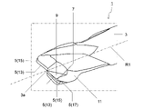
- FIG. 2 is an enlarged view of an area A1 shown in FIG. 1
- FIG. FIG. 2 is a plan view of the rotary tool shown in FIG. 1 as seen from the tip side
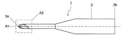
- FIG. 4 is a side view of the rotary tool shown in FIG. 3 as seen from the B1 direction
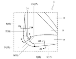
- 5 is an enlarged view of an area A2 shown in FIG. 4
- FIG. FIG. 4 is a side view of the rotary tool shown in FIG. 3 as seen from a direction B2
- 7 is an enlarged view of an area A3 shown in FIG. 6
- FIG. 8 is an enlarged view of an area A4 shown in FIG. 7
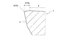
- FIG. 9 is a sectional view of the IX section in the rotary tool shown in FIG. 8;
- FIG. 9 is a cross-sectional view of the X cross section in the rotary tool shown in FIG. 8; 11 is an enlarged view of an area A5 shown in FIG. 10;
- FIG. FIG. 9 is a sectional view of the XII section in the rotary tool shown in FIG. 8;
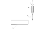
- 1 is a schematic diagram illustrating a step in a non-limiting embodiment of a method for manufacturing a machined workpiece;
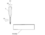
- FIG. 1 is a schematic diagram illustrating a step in a non-limiting embodiment of a method for manufacturing a machined workpiece;
- FIG. 1 is a schematic diagram illustrating a step in a non-limiting embodiment of a method for manufacturing a machined workpiece;
- FIG. 1 is a schematic diagram illustrating a step in a non-limiting embodiment of a method for manufacturing a machined workpiece;
- FIG. 1 is a schematic diagram illustrating
- Rotary tools may include, for example, end mills and milling tools.
- End mills may include, for example, square end mills, radius end mills and flat end mills.
- the rotary tool 1 in one non-limiting example shown in FIG. 1 is a radius end mill.
- the rotary tool may comprise any components not shown in the figures to which this specification refers.
- the dimensions of the members in each drawing do not faithfully represent the dimensions of the actual constituent members and the dimensional ratios of the respective members. These points are the same in the manufacturing method of the machined product 101, which will be described later.
- the rotary tool 1 in one non-limiting example shown in FIG. 1 may have a body 3 extending from a first end 3a to a second end 3b along an axis of rotation R1.
- the first end may be referred to as the "leading edge” and the second end may be referred to as the "trailing edge.”
- the first end 3a may be referred to as the front end 3a
- the second end 3b may be referred to as the rear end 3b.
- the main body 3 is rotatable in the direction of an arrow R2 around a rotation axis R1 as in a non-limiting example shown in FIGS. .
- the main body 3 in a non-limiting example shown in FIG. 1 is a so-called solid tool, which is composed of one member.
- the main body 3 is not limited to such a configuration, and may be configured by a plurality of members.
- the body 3 may consist of holders and inserts.
- the lower left end of the main body 3 may be the first end 3a and the upper right end may be the second end 3b.
- the left end of the body 3 may be the first end 3a and the right end may be the second end 3b.
- FIGS. 4 and 5 are diagrams showing a state in which the rotary tool 1 shown in FIGS. 4 and 5 is rotated at a predetermined angle in the rotation direction R2.
- FIG. 4 is a view of the rotary tool 1 shown in FIG. 3 as seen from the direction B1.
- FIG. 6 is a view of the rotary tool 1 shown in FIG. 3 as seen from the direction B2.
- FIG. 6 is a view seen from a direction shifted by 90° with respect to FIG.
- the body 3 in one non-limiting example shown in FIG. 1 may be cylindrical.
- the cylindrical shape is not limited to a cylinder in a strict sense.
- a discharge groove 11 (flute) through which chips flow may be provided on the outer circumference.
- the body 3 may have a cutting edge 5 , a rake face 7 , a gash face 9 and a discharge groove 11 .
- the cutting edge 5 may have a tip cutting edge 13, a corner cutting edge 15 and a peripheral cutting edge 17, as shown in FIGS. 2 and 3 as a non-limiting example.
- the number of the tip cutting edge 13, the corner cutting edge 15 and the peripheral cutting edge 17 may be one each, or may be plural.
- a non-limiting example rotary tool 1 shown in FIG. 2 has two tip cutting edges 13, corner cutting edges 15 and peripheral cutting edges 17, respectively.
- the plurality of tip cutting edges 13, corner cutting edges 15, and peripheral cutting edges 17 are rotationally symmetrical about the rotation axis R1 by 180 degrees. Therefore, one of the plurality of tip cutting edges 13, corner cutting edges 15, and peripheral cutting edges 17 will be focused on and explained.
- the corner edge 15 may be a portion of the cutting edge 5 located on the tip 3a side of the main body 3 and on the outer peripheral side.
- the corner edge 15 may have a convex curved shape.
- the curvature of the convex curve-shaped corner edge 15 may be constant, that is, the corner edge 15 may be arc-shaped, or the curvature of the convex curve-shaped corner edge 15 may not be constant.
- the corner edge 15 has an arc shape, the corner edge 15 has high durability.
- the tip edge 13 may be a portion of the cutting edge 5 located on the tip 3a side of the main body 3.
- the tip cutting edge 13 may have a linear shape.
- the linear shape is not limited to a straight line in a strict sense.
- the tip cutting edge 13 may have unevenness of about several tens of ⁇ m that is unavoidable in the manufacturing process.
- the tip cutting edge 13 may have a radius of curvature several tens of times larger than the radius of curvature of the corner cutting edge 15, and may have a gentle curved shape that can be regarded as a linear shape.
- the tip cutting edge 13 may be connected to the corner cutting edge 15 and may extend from the corner cutting edge 15 toward the rotation axis R1. In other words, the corner cutting edge 15 may extend from the tip cutting edge 13 towards the outer circumference of the body 3 .
- the tip cutting edge 13 may be orthogonal to the rotation axis R1 when viewed from the side, or may be inclined with respect to the rotation axis R1.
- the tip cutting edge 13 may be tilted with respect to the rotation axis R1 so as to approach the rear end 3b as it moves away from the rotation axis R1, and as shown in a non-limiting example shown in FIG. Therefore, it may be inclined with respect to the rotation axis R1 so as to approach the rear end 3b.
- the tip cutting edge 13 When the tip cutting edge 13 is orthogonal to the rotation axis R1, it is possible to use the entire tip cutting edge 13 as a so-called wiper edge.
- the tip cutting edge 13 When the tip cutting edge 13 is inclined with respect to the rotation axis R1 so as to approach the rear end 3b as it separates from the rotation axis R1, the cutting angle can be reduced, so the feed amount can be increased. Also, when the tip cutting edge 13 is inclined with respect to the rotation axis R1 so as to approach the rear end 3b as it approaches the rotation axis R1, it is possible to perform a so-called oblique sinking process.
- the peripheral cutting edge 17 may be a portion located on the outer periphery of the main body 3 .
- the peripheral cutting edge 17 may be connected to the corner cutting edge 15 and may extend from the corner cutting edge 15 toward the rear end 3b.
- the peripheral cutting edge 17 may have a linear shape, or may have a spiral shape extending rearward in the rotational direction R2 as it separates from the corner cutting edge 15 .
- the rake face 7 may be positioned along the cutting edge 5.
- the rake face 7 may be a surface on which chips generated by the cutting edge 5 rub against, or may be a surface for controlling the shape of the chips and the speed and direction of the flow of the chips.
- the rake face 7 may be connected to the cutting edge 5 or may be remote. For example, if a so-called land surface is connected to the cutting edge 5 in order to increase the strength of the cutting edge 5, the rake face 7 may be connected to the cutting edge 5 via this land surface.
- the rake face 7 may have a first rake face 19, a second rake face 21 and a third rake face 23, as in a non-limiting example shown in FIG.
- a first rake face 19 may be positioned along the tip cutting edge 13 .
- the second rake face 21 may be located along the corner cutting edge 15 .
- the third rake face 23 may be positioned along the peripheral cutting edge 17 .
- the first rake face 19 positioned along the tip cutting edge 13 may have a linear shape in a cross section perpendicular to the tip cutting edge 13, as in a non-limiting example shown in FIG.
- the first rake face 19 is flat, the first rake face 19 can be linear in cross section perpendicular to the tip edge 13 .
- the second rake face 21 positioned along the corner edge 15 may be concave in cross-section perpendicular to the corner edge 15, as in the non-limiting example shown in FIGS.
- the second rake face 21 has a concave shape
- the second rake face 21 can have a concave shape in a cross section perpendicular to the corner cutting edge 15 .
- Chips generated by the tip cutting edge 13 tend to flow over the first rake face 19 and advance in a direction orthogonal to the tip cutting edge 13 .
- chips generated by the corner edge 15 tend to flow over the second rake face 21 and advance in a direction perpendicular to the corner edge 15 . Therefore, the chips generated by the tip cutting edge 13 and the chips generated by the corner cutting edge 15 may collide with each other, resulting in chip clogging.
- the flow direction of the chips generated on the corner cutting edge 15 is from the chip generated on the tip cutting edge 13 on the second rake face 21. Easy to move away from. Therefore, chip clogging is less likely to occur.
- the rotation speed of the tip cutting edge 13 is slower than the rotation speed of the corner cutting edge 15 . Therefore, the flow speed of chips generated at the tip cutting edge 13 is slower than the flow speed of chips generated at the corner cutting edge 15 .
- the first rake face 19 has a linear shape in the cross section orthogonal to the tip cutting edge 13, the possibility that the flow of chips generated by the tip cutting edge 13 is excessively blocked at the first rake face 19 can be reduced. . Therefore, it is possible to reduce the possibility that the tip cutting edge 13 is clogged with chips.
- the shape of the second rake face 21 in the cross section orthogonal to the corner cutting edge 15 is not limited to a specific configuration.
- the second rake face 21 may be composed of two linear portions or one concave curved portion in a cross section orthogonal to the corner cutting edge 15 .
- the rake angle of the first rake face 19 is not limited to a specific value, it may be a negative value as in a non-limiting example shown in FIG.
- the negative value of the rake angle may mean that the rake face 7 is inclined forward in the rotational direction R ⁇ b>2 as the distance from the cutting edge 5 increases.
- the top is the front in the rotational direction R2, and the first rake face 19 is inclined upward as it moves away from the tip cutting edge 13 .
- the rake angle of the second rake face 21 is not limited to a specific value, it may be a negative value as in a non-limiting example shown in FIG.
- the upper side is the front in the rotational direction R2
- the second rake face 21 is inclined upward with increasing distance from the corner cutting edge 15 .
- the rake angle may be evaluated by the tangent line at the end of the rake face 7 that contacts the cutting edge 5 .
- the rake angle of the third rake face 23 is not limited to a specific value, it may be a negative value as in a non-limiting example shown in FIG.
- the top is the front in the rotational direction R2
- the third rake face 23 is inclined upward with distance from the peripheral cutting edge 17 .
- the second rake face 21, which has a concave shape in a cross section perpendicular to the corner cutting edge 15, may have a first portion 25 and a second portion 27 as in a non-limiting example shown in FIG.
- the first portion 25 may be a portion extending from the corner edge 15
- the second portion 27 may be a portion extending from the first portion 25 .
- the first portion 25 may be a portion located along the corner edge 15, and the second portion 27 may be a portion located closer to the rotation axis R1 than the first portion 25. .
- the first portion 25 may be linear and the second portion 27 may be concave curved.
- the first portion 25 has a linear shape
- chips generated by the corner cutting edge 5 can be smoothly advanced to the second rake face 21 .
- the second portion 27 has a concave curve shape, as described above, the flow direction of the chips generated by the corner cutting edge 15 tends to move away from the chips generated by the tip cutting edge 13 on the second rake face 21. .
- the risk of chip clogging on the second rake face 21 can be reduced, and chips generated at the corner edge 15 and the tip edge can be reduced.
- the risk of chip clogging due to the chips generated at 13 colliding can be reduced.
- the second rake face 21 further has a third portion 29 in addition to the first portion 25 and the second portion 27, as in a non-limiting example shown in FIG. good too.
- the third portion 29 may be a portion extending from the second portion 27 .
- the third portion 29 may be a portion located along the second portion 27 closer to the rotation axis R ⁇ b>1 than the second portion 27 .
- the third portion 29 may have a linear shape.
- the advancing direction of the chips whose flowing direction has changed in the second portion 27 tends to be stable. Therefore, it is possible to further reduce the risk of chip clogging due to collision between chips generated by the corner edge 15 and chips generated by the tip edge 13 .
- the angle formed by the first portion 25 and the third portion 29 is an obtuse angle. may In this case, the risk of chip clogging on the second rake face 21 can be further reduced.
- the first portion 25 is the first rake face as in a non-limiting example shown in FIG.
- a second portion 27 may be connected to the face 19 and the third rake face 23 and separated from the first rake face 19 and the third rake face 23 .
- the width of the first portion 25 in the direction perpendicular to the corner cutting edge 15 may become narrower as the distance from the first rake face 19 increases. Since the rotary tool 1 rotates around the rotation axis R1 in the cutting of the work material, the flow of chips generated at the portion of the corner edge 15 near the tip edge 13 spreads to the peripheral edge of the corner edge 15. It is slower than the chip flow that occurs in the portion located near 17 and tends to be unstable.
- the linear first portion 25 can have the function of smoothly advancing chips generated by the corner edge 15 to the second rake face 21 . Therefore, when the width of the first portion 25 in the direction perpendicular to the corner edge 15 is configured as described above, the chip guiding function of the corner edge 15 as a whole can be enhanced.
- the gash surface 9 may extend from the first rake surface 19 toward the rear end 3b.
- the gash surface 9 may be a surface for reducing the core thickness of the main body 3 on the tip 3a side, and may have a flat shape. Further, since the gash surface 9 may be a surface for reducing the core thickness of the main body 3 on the side of the tip 3a, as in a non-limiting example shown in FIG. A portion may exist in a region close to .
- the gash surface 9 may extend from the second rake surface 21 toward the rear end 3b.
- the second rake face 21 may be connected to the gash face 9 .
- the ridge line 31 forming the boundary between the second rake face 21 and the gash face 9 may be convex toward the second rake face 21 as in a non-limiting example shown in FIG.
- chips generated at the tip cutting edge 13 and advanced to the gash surface 9 through the first rake face 19 are less likely to flow into the second rake face 21 . Therefore, it is possible to further reduce the risk of chip clogging due to collision between chips generated by the corner edge 15 and chips generated by the tip edge 13 .
- the ridgeline 31 forming the boundary between the second rake face 21 and the gash face 9 may have a curved shape that is convex toward the second rake face 21 .
- the ridgeline 31 forming the boundary between the second rake face 21 and the gash face 9 may approach the rear end 3b as the outer circumference of the main body 3 approaches.
- the entire ridgeline 31 forming the boundary between the second rake face 21 and the gash face 9 may approach the rear end 3b as it approaches the outer circumference of the main body 3.
- the third rake face 23 positioned along the peripheral cutting edge 17 may have a linear shape in a cross section orthogonal to the peripheral cutting edge 17, as in a non-limiting example shown in FIG.
- the third rake face 23 when the third rake face 23 is flat, the third rake face 23 can have a linear shape in a cross section perpendicular to the peripheral cutting edge 17 .
- the width of the first rake face 19 in the direction perpendicular to the tip cutting edge 13 may become narrower as the distance from the second rake face 21 increases. A portion of the tip cutting edge 13 away from the second rake face 21 rotates at a slower speed than a portion located near the second rake face 21 . For this reason, the sharpness of the portion of the tip cutting edge 13 away from the second rake face 21 is likely to deteriorate.
- the second rake face of the tip cutting edge 13 can maintain the durability of the tip cutting edge 13 as a whole.
- a decrease in sharpness at a portion away from 21 is easily suppressed. Therefore, the sharpness of the tip cutting edge 13 as a whole can be enhanced.
- the rake angle of the first rake face 19 is a negative value, as in the non-limiting example shown in FIG. 9, the above effect tends to be noticeable.
- the width of the third rake face 23 in the direction orthogonal to the peripheral cutting edge 17 may become narrower as the distance from the second rake face 21 increases. A portion of the peripheral cutting edge 17 located near the second rake face 21 is likely to be subjected to a greater cutting load than a portion distant from the second rake face 21 .
- the second rake face 21 of the peripheral cutting edge 17 can maintain the sharpness of the peripheral cutting edge 17 as a whole.
- the durability of the portion located near the is likely to be enhanced. Therefore, the durability of the peripheral cutting edge 17 as a whole can be increased.
- the rake angle of the third rake face 23 has a negative value, as in the non-limiting example shown in FIG. 12, the above effect tends to be remarkable.
- the discharge groove 11 may extend from the gash surface 9, the second rake surface 21 and the third rake surface 23 toward the rear end 3b.
- the discharge groove 11 may be connected to the first rake face 19 or may be separated from the first rake face 19 .
- the discharge groove 11 may have a function of flowing chips generated by the cutting edge 5 toward the rear end 3b and discharging the chips to the outside.
- the discharge groove 11 may extend straight along the rotation axis R1, or may have a spiral shape extending rearward in the rotation direction R2 toward the rear end 3b.
- the angle formed by the discharge groove 11 with respect to the rotation axis R1 when viewed from the side may be a so-called twist angle.
- the twist angle of the discharge groove 11 is not limited to a specific value, and can be set to 5° to 60°, for example. However, the twist angle may be constant or may vary.
- the discharge groove 11 extends toward the rear end 3b of the main body 3, but does not have to reach the rear end 3b. In other words, the discharge groove 11 may be remote from the rear end 3b of the body 3. If the discharge groove 11 is distant from the rear end 3b of the main body 3, the part closer to the rear end 3b of the main body 3 than the discharge groove 11 may be a so-called shank. Also, the portion from the tip 3a of the main body 3 to the rear end of the discharge groove 11 in the direction along the rotation axis R1, in other words, the portion on the tip 3a side with respect to the gripping portion is a so-called cutting part. You can become
- a non-limiting example of the rotary tool 1 shown in FIG. 1 is a tool that is used for right-handed rotation, so the peripheral cutting edge 17 and the discharge groove 11 are right-handed, but the rotary tool 1 is not limited to this. For example, even if the tool is used for left rotation and the peripheral cutting edge 17 and the discharge groove 11 are twisted to the left, there is no problem.
- cemented carbide and cermet examples include cemented carbide and cermet.
- Cemented carbide compositions may include, for example, WC-Co, WC-TiC-Co and WC-TiC-TaC-Co.
- WC, TiC, TaC may be hard particles and Co may be the binder phase.
- the cermet may be a sintered composite material in which a ceramic component is combined with a metal.
- the cermet may include a titanium compound containing titanium carbide (TiC) or titanium nitride (TiN) as a main component.
- the surface of body 3 may be coated with a coating using a chemical vapor deposition (CVD) method or a physical vapor deposition (PVD) method.
- the composition of the coating may include titanium carbide (TiC), titanium nitride (TiN), titanium carbonitride (TiCN), or alumina ( Al2O3 ).
- the thickness of the coating may be set to, for example, 0.3 ⁇ m to 20 ⁇ m. In addition, the suitable range may differ depending on the composition of the coating.
- FIGS. 13 to 15 a non-limiting embodiment of a method for manufacturing a cut workpiece will be described in detail, taking as an example a case where the rotary tool 1 according to the non-limiting embodiment described above is used. Description will be made below with reference to FIGS. 13 to 15.
- FIG. 13 to 15 as an example of the method of manufacturing the workpiece 101, the process of milling the workpiece 103 is illustrated. Also, in order to facilitate visual understanding, the cut portions are hatched in FIGS. 14 and 15 .
- a method for manufacturing the cut workpiece 101 according to a non-limiting embodiment can include the following steps (1) to (3).
- the rotary tool 1 may be rotated in the direction of the arrow R2 about the rotation axis R1 to bring the rotary tool 1 closer to the workpiece 103 in the Y1 direction (see FIG. 13).
- This step may be performed, for example, by fixing the workpiece 103 on the table of the machine tool to which the rotary tool 1 is attached, and bringing the rotary tool 1 closer to it while rotating.
- the work material 103 and the rotary tool 1 may be brought relatively close to each other, and the work material 103 may be brought close to the rotary tool 1 .
- the rotating rotary tool 1 may be brought into contact with a desired position on the surface of the work piece 103 to cut the work piece 103. (See FIG. 14).
- the tip cutting edge 13, the corner cutting edge 15 and the peripheral cutting edge 17 may be brought into contact with desired positions on the surface of the work material 103.
- the rotary tool 1 may be separated from the workpiece 103 in the Y2 direction (see FIG. 15).
- the rotary tool 1 may be relatively separated from the work piece 103, for example, the work piece 103 may be separated from the rotary tool 1, similarly to the step (1) described above.
- cutting may include plunge machining, profiling, oblique sinking, and the like.
- the rotary tool 1 When the above-described cutting of the work material 103 is performed a plurality of times, for example, when performing a plurality of cuttings on one work material 103, the rotary tool 1 is rotated. The step of bringing the rotary tool 1 into contact with different portions of the work piece 103 may be repeated while maintaining the state where the work piece 103 is held.
Landscapes
- Engineering & Computer Science (AREA)
- Mechanical Engineering (AREA)
- Milling Processes (AREA)
Priority Applications (3)
| Application Number | Priority Date | Filing Date | Title |
|---|---|---|---|
| US18/574,042 US20240286208A1 (en) | 2021-07-01 | 2022-07-01 | Rotary tool and method for manufacturing machined product |
| JP2023532085A JP7526894B2 (ja) | 2021-07-01 | 2022-07-01 | 回転工具及び切削加工物の製造方法 |
| CN202280041387.8A CN117545576A (zh) | 2021-07-01 | 2022-07-01 | 旋转工具及切削加工物的制造方法 |
Applications Claiming Priority (2)
| Application Number | Priority Date | Filing Date | Title |
|---|---|---|---|
| JP2021-110206 | 2021-07-01 | ||
| JP2021110206 | 2021-07-01 |
Publications (1)
| Publication Number | Publication Date |
|---|---|
| WO2023277176A1 true WO2023277176A1 (ja) | 2023-01-05 |
Family
ID=84692778
Family Applications (1)
| Application Number | Title | Priority Date | Filing Date |
|---|---|---|---|
| PCT/JP2022/026441 Ceased WO2023277176A1 (ja) | 2021-07-01 | 2022-07-01 | 回転工具及び切削加工物の製造方法 |
Country Status (4)
| Country | Link |
|---|---|
| US (1) | US20240286208A1 (https=) |
| JP (1) | JP7526894B2 (https=) |
| CN (1) | CN117545576A (https=) |
| WO (1) | WO2023277176A1 (https=) |
Cited By (1)
| Publication number | Priority date | Publication date | Assignee | Title |
|---|---|---|---|---|
| JPWO2019188135A1 (ja) * | 2018-03-27 | 2021-02-12 | 日本特殊陶業株式会社 | エンドミル本体及びエンドミル |
Citations (3)
| Publication number | Priority date | Publication date | Assignee | Title |
|---|---|---|---|---|
| JP2006026839A (ja) * | 2004-07-20 | 2006-02-02 | Nachi Fujikoshi Corp | ラジアスエンドミル |
| WO2010050391A1 (ja) * | 2008-10-29 | 2010-05-06 | 住友電工ハードメタル株式会社 | ボールエンドミル |
| WO2019188135A1 (ja) * | 2018-03-27 | 2019-10-03 | 日本特殊陶業株式会社 | エンドミル本体及びエンドミル |
Family Cites Families (20)
| Publication number | Priority date | Publication date | Assignee | Title |
|---|---|---|---|---|
| US5779399A (en) * | 1996-03-05 | 1998-07-14 | Mcdonnell Douglas | Rotary cutting apparatus |
| KR101093461B1 (ko) * | 2002-12-26 | 2011-12-13 | 미쓰비시 마테리알 가부시키가이샤 | 레디어스 엔드밀 |
| JP2006212744A (ja) * | 2005-02-04 | 2006-08-17 | Nisshin Kogu Kk | エンドミル |
| JP2007030074A (ja) * | 2005-07-25 | 2007-02-08 | Mitsubishi Materials Kobe Tools Corp | ラジアスエンドミル及び切削加工方法 |
| WO2007125613A1 (ja) * | 2006-04-28 | 2007-11-08 | Union Tool Co. | 回転切削工具 |
| JP2009241190A (ja) * | 2008-03-31 | 2009-10-22 | Sumitomo Electric Hardmetal Corp | Cbnラジアスエンドミル |
| JP5267556B2 (ja) * | 2008-03-31 | 2013-08-21 | 三菱マテリアル株式会社 | ラジアスエンドミルおよび切削インサート |
| JP2011020192A (ja) * | 2009-07-14 | 2011-02-03 | Sumitomo Electric Hardmetal Corp | ねじれ刃ラジアスエンドミル |
| KR101746483B1 (ko) * | 2011-06-17 | 2017-06-13 | 미츠비시 히타치 쓰루 가부시키가이샤 | 다날 엔드밀 |
| CN104023884B (zh) * | 2011-12-27 | 2016-05-11 | 京瓷株式会社 | 圆角立铣刀 |
| EP2848342B1 (de) * | 2013-09-13 | 2018-06-27 | Fraisa SA | Vollfräswerkzeug zur rotierenden Materialbearbeitung |
| US9901995B2 (en) * | 2013-11-08 | 2018-02-27 | Mitsubishi Hitachi Tool Engineering, Ltd. | Radius end mill and cutting work method |
| JP6477015B2 (ja) * | 2015-02-27 | 2019-03-06 | 三菱マテリアル株式会社 | ラジアスエンドミル |
| US20170341162A1 (en) * | 2015-02-27 | 2017-11-30 | Mitsubishi Materials Corporation | Radius end mill, ball end mill, and end mill |
| US10131003B2 (en) * | 2015-11-23 | 2018-11-20 | Iscar, Ltd. | Cemented carbide corner radius end mill with continuously curved rake ridge and helical flute design |
| JP6708668B2 (ja) | 2016-01-27 | 2020-06-10 | 京セラ株式会社 | エンドミル及び切削加工物の製造方法 |
| CN109414769B (zh) | 2016-06-30 | 2020-12-22 | 日本特殊陶业株式会社 | 端铣刀主体和圆角端铣刀 |
| IL264757B (en) * | 2019-02-10 | 2022-07-01 | Hanita Metal Works Ltd | End mill with independent rake surfaces |
| JP2021010957A (ja) * | 2019-07-04 | 2021-02-04 | 株式会社Moldino | ラジアスエンドミル |
| US11865629B2 (en) * | 2021-11-04 | 2024-01-09 | Kennametal Inc. | Rotary cutting tool with high ramp angle capability |
-
2022
- 2022-07-01 JP JP2023532085A patent/JP7526894B2/ja active Active
- 2022-07-01 US US18/574,042 patent/US20240286208A1/en active Pending
- 2022-07-01 CN CN202280041387.8A patent/CN117545576A/zh active Pending
- 2022-07-01 WO PCT/JP2022/026441 patent/WO2023277176A1/ja not_active Ceased
Patent Citations (3)
| Publication number | Priority date | Publication date | Assignee | Title |
|---|---|---|---|---|
| JP2006026839A (ja) * | 2004-07-20 | 2006-02-02 | Nachi Fujikoshi Corp | ラジアスエンドミル |
| WO2010050391A1 (ja) * | 2008-10-29 | 2010-05-06 | 住友電工ハードメタル株式会社 | ボールエンドミル |
| WO2019188135A1 (ja) * | 2018-03-27 | 2019-10-03 | 日本特殊陶業株式会社 | エンドミル本体及びエンドミル |
Cited By (2)
| Publication number | Priority date | Publication date | Assignee | Title |
|---|---|---|---|---|
| JPWO2019188135A1 (ja) * | 2018-03-27 | 2021-02-12 | 日本特殊陶業株式会社 | エンドミル本体及びエンドミル |
| JP7341058B2 (ja) | 2018-03-27 | 2023-09-08 | Ntkカッティングツールズ株式会社 | エンドミル本体及びエンドミル |
Also Published As
| Publication number | Publication date |
|---|---|
| CN117545576A (zh) | 2024-02-09 |
| JP7526894B2 (ja) | 2024-08-01 |
| JPWO2023277176A1 (https=) | 2023-01-05 |
| US20240286208A1 (en) | 2024-08-29 |
Similar Documents
| Publication | Publication Date | Title |
|---|---|---|
| JP6860657B2 (ja) | 回転工具及び切削加工物の製造方法 | |
| JP7168673B2 (ja) | 切削インサート、回転工具及び切削加工物の製造方法 | |
| JP6892503B2 (ja) | 回転工具 | |
| US11351617B2 (en) | Rotating tool | |
| JP7386339B2 (ja) | ドリル及び切削加工物の製造方法 | |
| JP7023275B2 (ja) | 回転工具 | |
| JP6788032B2 (ja) | 回転工具 | |
| JP7103933B2 (ja) | 切削インサート、回転工具及び切削加工物の製造方法 | |
| JP7344321B2 (ja) | 回転工具及び切削加工物の製造方法 | |
| JP6894506B2 (ja) | エンドミル及び切削加工物の製造方法 | |
| WO2023277176A1 (ja) | 回転工具及び切削加工物の製造方法 | |
| WO2019088013A1 (ja) | ドリル及び切削加工物の製造方法 | |
| JP6882517B2 (ja) | 回転工具 | |
| JP7727830B2 (ja) | ドリル及び切削加工物の製造方法 | |
| JP7417707B2 (ja) | エンドミル及び切削加工物の製造方法 | |
| CN115968328A (zh) | 切削刀片、旋转刀具以及切削加工物的制造方法 | |
| JP7279163B2 (ja) | 回転工具及び切削加工物の製造方法 | |
| JP7060462B2 (ja) | 回転工具及び切削加工物の製造方法 | |
| KR20250168415A (ko) | 드릴 및 절삭 가공물의 제조 방법 | |
| CN114786850A (zh) | 钻头以及切削加工物的制造方法 | |
| JPWO2018180780A1 (ja) | 切削インサート、ドリル及び切削加工物の製造方法 | |
| JP2018140449A (ja) | 回転工具 |
Legal Events
| Date | Code | Title | Description |
|---|---|---|---|
| 121 | Ep: the epo has been informed by wipo that ep was designated in this application |
Ref document number: 22833321 Country of ref document: EP Kind code of ref document: A1 |
|
| WWE | Wipo information: entry into national phase |
Ref document number: 2023532085 Country of ref document: JP |
|
| WWE | Wipo information: entry into national phase |
Ref document number: 202280041387.8 Country of ref document: CN |
|
| WWE | Wipo information: entry into national phase |
Ref document number: 18574042 Country of ref document: US |
|
| NENP | Non-entry into the national phase |
Ref country code: DE |
|
| 122 | Ep: pct application non-entry in european phase |
Ref document number: 22833321 Country of ref document: EP Kind code of ref document: A1 |