WO2023277003A1 - 船舶、船舶制御装置、船舶制御方法およびプログラム - Google Patents
船舶、船舶制御装置、船舶制御方法およびプログラム Download PDFInfo
- Publication number
- WO2023277003A1 WO2023277003A1 PCT/JP2022/025713 JP2022025713W WO2023277003A1 WO 2023277003 A1 WO2023277003 A1 WO 2023277003A1 JP 2022025713 W JP2022025713 W JP 2022025713W WO 2023277003 A1 WO2023277003 A1 WO 2023277003A1
- Authority
- WO
- WIPO (PCT)
- Prior art keywords
- ship
- vessel
- engine
- bucket
- control
- Prior art date
- Legal status (The legal status is an assumption and is not a legal conclusion. Google has not performed a legal analysis and makes no representation as to the accuracy of the status listed.)
- Ceased
Links
Images




Classifications
-
- B—PERFORMING OPERATIONS; TRANSPORTING
- B63—SHIPS OR OTHER WATERBORNE VESSELS; RELATED EQUIPMENT
- B63B—SHIPS OR OTHER WATERBORNE VESSELS; EQUIPMENT FOR SHIPPING
- B63B79/00—Monitoring properties or operating parameters of vessels in operation
- B63B79/40—Monitoring properties or operating parameters of vessels in operation for controlling the operation of vessels, e.g. monitoring their speed, routing or maintenance schedules
-
- B—PERFORMING OPERATIONS; TRANSPORTING
- B63—SHIPS OR OTHER WATERBORNE VESSELS; RELATED EQUIPMENT
- B63H—MARINE PROPULSION OR STEERING
- B63H11/00—Marine propulsion by water jets
- B63H11/02—Marine propulsion by water jets the propulsive medium being ambient water
- B63H11/10—Marine propulsion by water jets the propulsive medium being ambient water having means for deflecting jet or influencing cross-section thereof
- B63H11/107—Direction control of propulsive fluid
- B63H11/11—Direction control of propulsive fluid with bucket or clamshell-type reversing means
-
- B—PERFORMING OPERATIONS; TRANSPORTING
- B63—SHIPS OR OTHER WATERBORNE VESSELS; RELATED EQUIPMENT
- B63H—MARINE PROPULSION OR STEERING
- B63H21/00—Use of propulsion power plant or units on vessels
- B63H21/21—Control means for engine or transmission, specially adapted for use on marine vessels
-
- B—PERFORMING OPERATIONS; TRANSPORTING
- B63—SHIPS OR OTHER WATERBORNE VESSELS; RELATED EQUIPMENT
- B63H—MARINE PROPULSION OR STEERING
- B63H25/00—Steering; Slowing-down otherwise than by use of propulsive elements; Dynamic anchoring, i.e. positioning vessels by means of main or auxiliary propulsive elements
- B63H25/46—Steering or dynamic anchoring by jets or by rudders carrying jets
-
- B—PERFORMING OPERATIONS; TRANSPORTING
- B63—SHIPS OR OTHER WATERBORNE VESSELS; RELATED EQUIPMENT
- B63H—MARINE PROPULSION OR STEERING
- B63H21/00—Use of propulsion power plant or units on vessels
- B63H21/21—Control means for engine or transmission, specially adapted for use on marine vessels
- B63H2021/216—Control means for engine or transmission, specially adapted for use on marine vessels using electric control means
-
- B—PERFORMING OPERATIONS; TRANSPORTING
- B63—SHIPS OR OTHER WATERBORNE VESSELS; RELATED EQUIPMENT
- B63H—MARINE PROPULSION OR STEERING
- B63H25/00—Steering; Slowing-down otherwise than by use of propulsive elements; Dynamic anchoring, i.e. positioning vessels by means of main or auxiliary propulsive elements
- B63H25/46—Steering or dynamic anchoring by jets or by rudders carrying jets
- B63H2025/465—Jets or thrusters substantially used for steering or dynamic anchoring only, with means for retracting, or otherwise moving to a rest position outside the water flow around the hull
Definitions
- the present invention relates to a ship, a ship control device, a ship control method, and a program.
- This application claims priority based on Japanese Patent Application No. 2021-106920 filed in Japan on June 28, 2021, the contents of which are incorporated herein.
- Patent Document 1 a small boat having a jet propulsion device is known (see Patent Document 1, for example).
- the bucket is configured to be switchable between a raised position (forward position) and a lowered position (reverse position).
- the water jets jetted from the nozzles are directed toward the rear of the hull without hitting the bucket, so the small boat moves forward.
- the water flow jetted from the nozzle hits the bucket and travels forward of the hull, causing the small boat to move backward.
- Patent Literature 1 does not describe control of keeping the ship at a fixed point. Therefore, according to the technique described in Patent Document 1, it is not possible to appropriately control the vessel fixed-point holding.
- a jet propulsion watercraft that moves forward by jetting a jet backward from a jet propulsion mechanism (see, for example, Patent Document 2).
- the jet propulsion watercraft described in Patent Document 2 includes a bucket that changes the direction of the jet flow from the jet propulsion mechanism.
- the bucket is movable between an advanced position and an operating position, the advanced position being a position in which the bucket is retracted from the jet outlet.
- the working position is the position where the bucket faces the jet outlet.
- the jet propulsion watercraft moves backward by arranging the bucket at the first operating position (reverse position).
- Patent Document 2 describes that the jet propulsion watercraft is held at a fixed position by disposing the bucket at the second operating position (neutral position).
- the jet propulsion boat cannot be operated simply by arranging the bucket in a neutral position, as described in Patent Document 2. cannot be held in place (fixed point holding).
- an object of the present invention is to provide a ship, a ship control device, a ship control method, and a program capable of improving the controllability of keeping the ship at a fixed point.
- One aspect of the present invention includes an engine that outputs a driving force, a jet propulsion device that generates a propulsion force for a ship by the driving force output from the engine, and a ship control device that controls the engine and the jet propulsion device. and a vessel position detection unit that detects an actual vessel position, which is the actual position of the vessel, wherein the jet propulsion device ejects a jet stream generated by a driving force output from the engine.
- a bucket for changing the direction of the jet jet ejected from the nozzle, wherein the position of the bucket is a forward position where the jet propulsion device generates a propulsive force for advancing the ship, and a forward position where the jet propulsion device generates and a forward intermediate position between the forward position and the neutral position.
- a vessel fixed-point holding mode for executing feedback control of the engine and the jet propulsion device based on the deviation between the target vessel position and the actual vessel position, and in the vessel fixed-point holding mode, the forward side A marine vessel in which both control of the position of the bucket, including intermediate positions, and control of the rotational speed of the engine are performed.
- One aspect of the present invention includes an engine that outputs a driving force, a jet propulsion device that generates a propulsion force for a ship by the driving force output from the engine, and a ship control device that controls the engine and the jet propulsion device. and a vessel position detection unit that detects an actual vessel position, which is the actual position of the vessel, wherein the jet propulsion device ejects a jet stream generated by a driving force output from the engine.
- the position of the bucket is a forward position where the jet propulsion device generates a propulsive force for advancing the ship, and a forward position where the jet propulsion device generates a neutral position where the jet propulsion device does not generate a propulsive force for moving the vessel, a reverse position where the jet propulsion device generates a propulsive force for moving the ship backward, and an intermediate position on the reverse side between the reverse position and the neutral position
- the ship control device executes feedback control of the engine and the jet propulsion device based on a deviation between a target ship position, which is a preset target position of the ship, and an actual ship position. and in which both the position control of the bucket including the reverse side intermediate position and the rotation speed control of the engine are executed in the ship fixed point holding mode.
- One aspect of the present invention includes an engine that outputs a driving force, a jet propulsion device that generates a propulsion force for a ship by the driving force output from the engine, and a ship control device that controls the engine and the jet propulsion device. and a vessel position detection unit that detects an actual vessel position, which is the actual position of the vessel, wherein the jet propulsion device ejects a jet stream generated by a driving force output from the engine.
- the position of the bucket is a forward position where the jet propulsion device generates a propulsive force for advancing the ship, and a forward position where the jet propulsion device generates a neutral position in which the jet propulsion device does not generate a propulsive force to move the vessel; a reverse position in which the jet propulsion device generates a propulsive force to move the ship backward; and a forward intermediate position between the forward position and the neutral position and an intermediate position on the reverse side between the reverse position and the neutral position.
- One aspect of the present invention includes an engine that outputs a driving force, a jet propulsion device that generates a propulsion force for a ship by means of the driving force output from the engine, and an actual ship position that is the actual position of the ship.
- a ship position detector wherein the jet propulsion device includes a nozzle for ejecting a jet stream generated by a driving force output from the engine; a bucket for changing the direction of the ejected jet stream, wherein the position of the bucket is a forward position where the jet propulsion device generates a propulsive force for moving the ship forward;
- a target vessel including at least a neutral position where no jet propulsion device is generated and a forward intermediate position between the forward position and the neutral position, wherein the vessel control device is a preset target position of the vessel.
- It has a vessel fixed-point holding mode for executing feedback control of the engine and the jet propulsion device based on the deviation between the position and the actual vessel position, and in the vessel fixed-point holding mode, the bucket including the forward side intermediate position.
- a ship control device that performs both position control and rotational speed control of the engine.
- One aspect of the present invention includes an engine that outputs a driving force, a jet propulsion device that generates a propulsion force for a ship by means of the driving force output from the engine, and an actual ship position that is the actual position of the ship.
- a ship position detector wherein the jet propulsion device includes a nozzle for ejecting a jet stream generated by a driving force output from the engine; a bucket for changing the direction of the ejected jet stream, wherein the position of the bucket is a forward position where the jet propulsion device generates a propulsive force for moving the ship forward; At least a neutral position in which a jet propulsion device does not generate, a reverse position in which the jet propulsion device generates a propulsive force to reverse the ship, and a reverse intermediate position between the reverse position and the neutral position,
- the vessel control device has a vessel fixed-point holding mode for executing feedback control of the engine and the jet propulsion device based on a deviation between a target vessel position, which is a preset
- One aspect of the present invention includes an engine that outputs a driving force, a jet propulsion device that generates a propulsion force for a ship by means of the driving force output from the engine, and an actual ship position that is the actual position of the ship.
- a ship position detector wherein the jet propulsion device includes a nozzle for ejecting a jet stream generated by a driving force output from the engine; a bucket for changing the direction of the ejected jet stream, wherein the position of the bucket is a forward position where the jet propulsion device generates a propulsive force for moving the ship forward; a neutral position in which the jet propulsion device does not generate; a reverse position in which the jet propulsion device generates a propulsive force for moving the ship backward; an intermediate position on the forward side between the forward position and the neutral position; and the reverse position.
- the engine and a vessel fixed-point holding mode for executing feedback control of the jet propulsion device, wherein, in the vessel fixed-point holding mode, control of the position of the bucket including the forward side intermediate position and the reverse side intermediate position; and the engine It is a ship control device that performs both control of the rotational speed of the
- One aspect of the present invention includes an engine that outputs a driving force, a jet propulsion device that generates a propulsion force for a ship by means of the driving force output from the engine, and an actual ship position that is the actual position of the ship.
- a ship position detector wherein the jet propulsion device includes a nozzle for ejecting a jet stream generated by a driving force output from the engine; and a bucket for changing the direction of the jet stream, wherein the position of the bucket is a forward position where the jet propulsion device generates a propulsive force for moving the ship forward, and a forward position where the jet propulsion device generates a propulsive force for moving the ship.
- a vessel fixed-point holding step for executing feedback control of the engine and the jet propulsion device based on, and when executing the vessel fixed-point holding step, controlling the position of the bucket including the forward intermediate position; and A vessel control method in which both control of the rotation speed of the engine is performed.
- One aspect of the present invention includes an engine that outputs a driving force, a jet propulsion device that generates a propulsion force for a ship by means of the driving force output from the engine, and an actual ship position that is the actual position of the ship.
- a ship position detector wherein the jet propulsion device includes a nozzle for ejecting a jet stream generated by a driving force output from the engine; and a bucket for changing the direction of the jet stream, wherein the position of the bucket is a forward position where the jet propulsion device generates a propulsive force for moving the ship forward, and a forward position where the jet propulsion device generates a propulsive force for moving the ship.
- At least a neutral position in which no device is generated, a reverse position in which the jet propulsion device generates a propulsive force for moving the ship backward, and a backward intermediate position between the reverse position and the neutral position are set in advance.
- a ship control method in which both control of the position of the bucket, including the intermediate position on the reverse side, and control of the rotational speed of the engine are sometimes performed.
- One aspect of the present invention includes an engine that outputs a driving force, a jet propulsion device that generates a propulsion force for a ship by means of the driving force output from the engine, and an actual ship position that is the actual position of the ship.
- a ship position detector wherein the jet propulsion device includes a nozzle for ejecting a jet stream generated by a driving force output from the engine; and a bucket for changing the direction of the jet stream, wherein the position of the bucket is a forward position where the jet propulsion device generates a propulsive force for moving the ship forward, and a forward position where the jet propulsion device generates a propulsive force for moving the ship.
- a neutral position where no equipment is generated a reverse position where the jet propulsion device generates a propulsive force for moving the vessel backward
- a forward side intermediate position between the forward position and the neutral position the reverse position and the neutral position.
- feedback control of the engine and the jet propulsion device based on the deviation between a target ship position, which is a preset target position of the ship, and the actual ship position.
- One aspect of the present invention includes an engine that outputs a driving force, a jet propulsion device that generates a propulsion force for a ship by means of the driving force output from the engine, and an actual ship position that is the actual position of the ship.
- a computer mounted on the ship which includes a ship position detection unit, based on a deviation between a target ship position, which is a preset target position of the ship, and an actual ship position, feedback of the engine and the jet propulsion device.
- a program for executing a vessel fixed-point holding step for executing control wherein the jet propulsion device includes a nozzle for ejecting a jet stream generated by a driving force output from the engine, and a nozzle for ejecting a jet stream from the nozzle a bucket for changing the direction of the jet stream, wherein the position of the bucket is a forward position where the jet propulsion device generates a propulsive force for moving the ship forward; and a forward intermediate position between the forward position and the neutral position, and control of the position of the bucket including the forward intermediate position during execution of the vessel fixed point holding step , and control of the rotation speed of the engine are both executed.
- One aspect of the present invention includes an engine that outputs a driving force, a jet propulsion device that generates a propulsion force for a ship by means of the driving force output from the engine, and an actual ship position that is the actual position of the ship.
- a computer mounted on the ship which includes a ship position detection unit, based on a deviation between a target ship position, which is a preset target position of the ship, and an actual ship position, feedback of the engine and the jet propulsion device.
- a program for executing a vessel fixed-point holding step for executing control wherein the jet propulsion device includes a nozzle for ejecting a jet stream generated by a driving force output from the engine, and a nozzle for ejecting a jet stream from the nozzle a bucket for changing the direction of the jet stream, wherein the position of the bucket is a forward position where the jet propulsion device generates a propulsive force for moving the ship forward; , a reverse position in which the jet propulsion device generates a propulsive force for moving the ship backward, and an intermediate position on the reverse side between the reverse position and the neutral position.
- the program executes both control of the position of the bucket including the intermediate position on the reverse side and control of the rotational speed of the engine when the holding step is executed.
- One aspect of the present invention includes an engine that outputs a driving force, a jet propulsion device that generates a propulsion force for a ship by means of the driving force output from the engine, and an actual ship position that is the actual position of the ship.
- a computer mounted on the ship which includes a ship position detection unit, based on a deviation between a target ship position, which is a preset target position of the ship, and an actual ship position, feedback of the engine and the jet propulsion device.
- a program for executing a vessel fixed-point holding step for executing control wherein the jet propulsion device includes a nozzle for ejecting a jet stream generated by a driving force output from the engine, and a nozzle for ejecting a jet stream from the nozzle a bucket for changing the direction of the jet stream, wherein the position of the bucket is a forward position where the jet propulsion device generates a propulsive force for moving the ship forward; a reverse position where the jet propulsion device generates a propulsive force for moving the vessel backward; an intermediate position on the forward side between the forward position and the neutral position; and the reverse position and the neutral position. and a reverse side intermediate position between and, when executing the vessel fixed point holding step, control of the position of the bucket including the forward side intermediate position and the reverse side intermediate position, and the rotational speed of the engine It is the program in which both controls are executed.
- the present invention it is possible to provide a ship, a ship control device, a ship control method, and a program capable of improving the controllability of keeping the ship at a fixed point.
- FIG. 4 is a diagram showing an example of a nozzle and bucket configuration; It is a figure which shows an example of the position of the bucket controlled by the bucket position control part of a ship control apparatus at the time of ship fixed point holding mode of a ship control apparatus. 4 is a flowchart for explaining an example of processing executed by the ship control device for the ship of the first embodiment; FIG. 11 is a diagram for explaining the position of the bucket controlled by the bucket position control section of the ship control device of the ship control device of the second embodiment in the ship fixed point holding mode; FIG.
- FIG. 11 is a diagram showing an example of a position of a bucket controlled by a bucket position control section of a ship control device for a ship according to the third embodiment in a ship fixed point holding mode; It is a flow chart for explaining an example of processing performed by a ship control device of a ship of a 3rd embodiment.
- FIG. 12 is a diagram for explaining the position of the bucket controlled by the bucket position control unit of the ship control device of the ship control device of the fourth embodiment in the ship fixed point holding mode;
- FIG. 12 is a flow chart for explaining an example of processing executed by a ship control device for a ship according to a fifth embodiment;
- FIG. FIG. 10 is a diagram showing an example of control that can be performed on the ships of the first to seventh embodiments;
- FIG. 10 is a diagram showing an example of control that can be performed on the ships of the first to seventh embodiments;
- FIG. 10 is a diagram showing an example of control that can be performed on the ships of the first to seventh embodiments;
- FIG. 10 is a diagram showing another example of control that can be performed in the ships of the first to seventh embodiments;
- FIG. 10 is a diagram showing another example of control that can be performed in the ships of the first to seventh embodiments;
- FIG. 10 is a diagram showing another example of control that can be performed in the ships of the first to seventh embodiments;
- FIG. 1 is a diagram showing an example of a ship 1 of the first embodiment.
- the boat 1 of the first embodiment has the same basic functions as the personal watercraft (PWC, personal watercraft) described in FIG. 1 of Patent Document 1 or Patent Document 2, for example.
- PWC personal watercraft
- the ship 1 includes, for example, an engine 11 , a jet propulsion device 12 , a ship control device 13 , a ship position detector 14 and an operation unit 15 .
- the engine 11 outputs driving force.
- the jet propulsion device 12 generates a propulsion force for the ship 1 by driving force output from the engine 11 .
- the jet propulsion device 12 includes a nozzle 12A and a bucket 12B.
- the nozzle 12 ⁇ /b>A ejects a jet stream generated by the driving force output from the engine 11 .
- Bucket 12B changes the direction of the jet flow ejected from nozzle 12A.
- FIG. 2 is a diagram showing an example of the configuration of the nozzle 12A and bucket 12B.
- FIG. 2 is a diagram for explaining an example of the basic position of the bucket 12B.
- FIG. 2A shows the positional relationship between the nozzle 12A and the bucket 12B and the jet flow when the bucket 12B is arranged at the forward position F.
- FIG. 2B shows the positional relationship between the nozzle 12A and the bucket 12B and the jet flow when the bucket 12B is placed at the neutral position N.
- FIG. FIG. 2(C) shows the positional relationship between the nozzle 12A and the bucket 12B and the jet flow when the bucket 12B is placed at the reverse position R.
- the jet propulsion device 12 when the bucket 12B is positioned at the forward position F, the jet flow ejected from the nozzle 12A does not hit the bucket 12B. That is, the direction of the jet flow ejected from the nozzle 12A is not changed by the bucket 12B. As a result, in a state where the bucket 12B is positioned at the forward position F, the jet propulsion device 12 generates a propulsive force that moves the ship 1 forward (that is, a propulsive force that moves the ship 1 rightward in FIG. 2A). do. As shown in FIG.
- the bucket 12B is configured to be rotatable around the rotation center axis extending in the horizontal direction (front side-back side direction in FIG. 2). However, it may be configured to be rotatable around a rotation center axis extending in the vertical direction (vertical direction in FIG. 2).
- the bucket 12B may be composed of two members, and the two members may be configured to open to the left and right.
- the ship control device 13 controls the engine 11 and the jet propulsion device 12, and the like.
- the ship control device 13 includes, for example, a bucket position control section 13A and an engine rotation speed control section 13B.
- the bucket position control unit 13A controls the position of the bucket 12B (for example, control for placing the bucket 12B at the forward position F, control for placing the bucket 12B at the neutral position N, control for placing the bucket 12B at the reverse position R, etc.). conduct.
- the engine rotation speed control unit 13B controls the rotation speed of the engine 11 (that is, controls to change the strength of the jet flow shown in FIG. 2).
- the vessel position detector 14 detects the actual vessel position, which is the actual position of the vessel 1 .
- the vessel position detector 14 includes, for example, a GPS (Global Positioning System) device.
- the GPS device calculates the position coordinates of the ship 1 by receiving signals from multiple GPS satellites.
- the operation unit 15 receives an input operation from the operator.
- the operating section 15 includes a throttle operating section 15A and a shift operating section 15B.
- the throttle operation unit 15A is configured in the same manner as the throttle operation unit described in Patent Document 2, for example, and receives an input operation by the operator who adjusts the rotation speed of the engine 11 .
- the shift operation unit 15B is configured in the same manner as the shift operation unit described in Patent Document 2, for example. Accept operations.
- the bucket position control unit 13A changes the position of the bucket 12B to any one of the forward position F, the neutral position N, and the reverse position R based on the operator's input operation received by the shift operation unit 15B. to control.
- the engine rotation speed control unit 13B controls the rotation speed of the engine 11 (the jet flow shown in FIG. 2) based on the operator's input operation received by the throttle operation unit 15A. control to change strength).
- the vessel control device 13 not only has the above-described normal mode, but also has a vessel fixed point holding mode.
- the vessel control device 13 operates the engine 11 and the jet propulsion device 12 based on the deviation between the target vessel position, which is the preset target position of the vessel 1, and the actual vessel position.
- Feedback control for example, PID control, etc.
- the target ship position is set in advance according to, for example, a ship operator's input operation (for example, the ship operator turns on a switch (not shown) when the ship 1 is at a desired position).
- the target vessel position may be set in advance by, for example, the operator entering numerically the coordinates of the desired position of the vessel 1 .
- FIG. 3 is a diagram showing an example of the position of the bucket 12B controlled by the bucket position control section 13A of the ship control device 13 when the ship control device 13 is in the ship fixed point holding mode.
- the positions of the bucket 12B that can be placed by the bucket position control section 13A of the ship control device 13 during the ship fixed point holding mode of the ship control device 13 are the neutral position N, the forward position F, and their Three forward-moving intermediate positions N+1, N+2, and N+3 located in between are set. That is, the positions of the bucket 12B that can be arranged by the bucket position control section 13A in the vessel fixed point holding mode of the vessel control device 13 are the neutral position N, the forward intermediate position N+1, the forward intermediate position N+2, and the forward intermediate position.
- N+3 and forward position F are included.
- three forward intermediate positions N+1, N+2, and N+3 are set as forward intermediate positions between the neutral position N and the forward position F. Any number of forward intermediate positions other than three may be set as forward intermediate positions between .
- the rotation angle ⁇ of the bucket 12B required to move the bucket 12B from the neutral position N to the forward position F is divided into four. Further, the position where the bucket 12B is rotated by ( ⁇ /4) from the neutral position N is set as the forward side intermediate position N+1, and the position where the bucket 12B is rotated by (2 ⁇ /4) from the neutral position N is , and the position where the bucket 12B is rotated by (3 ⁇ /4) from the neutral position N is set as the forward intermediate position N+3. In the example shown in FIG.
- forward side intermediate positions N+1, N+2, and N+3 are located at positions obtained by dividing the rotation angle ⁇ of the bucket 12B required to move the bucket 12B from the neutral position N to the forward position F at equal angular intervals.
- the rotation angles of the bucket 12B required to move the bucket 12B from N+3 to the forward position F may differ from each other.
- the ship control device 13 controls the position of the bucket 12B (the bucket 12B is positioned at the neutral position N, the forward intermediate positions N+1, N+2, N+3, and the forward position).
- F the rotation speed of the engine 11
- the vessel control device 13 sets the rotation speed of the engine 11 to a predetermined value so that the vessel 1 is held at the target vessel position. is set to any one of the forward position F, the neutral position N and the three forward intermediate positions N+1, N+2 and N+3.
- Table 1 shows an example of the correspondence between the rotation speed of the engine 11, the position of the bucket 12B, and the like in the vessel fixed point holding mode of the vessel control device 13.
- the control amount feedback control amount
- the bucket position controller 13A of the ship control device 13 places the bucket 12B at the neutral position N.
- the bucket position control unit 13A controls the position of the bucket 12B to the neutral position N even if the shift operation unit 15B does not accept the operator's input operation.
- the engine rotation speed control section 13B of the vessel control device 13 controls the rotation speed of the engine 11 to "IDLE” (the rotation speed of the engine 11 in the idling state). Specifically, the engine rotation speed control unit 13B controls the rotation speed of the engine 11 to "IDLE” even if the throttle operation unit 15A does not accept the input operation of the boat operator. Therefore, the jet propulsion device 12 does not generate a propulsive force for moving the ship 1, and the ship 1 is held at the target ship position.
- the control amount calculated by the ship control device 13 becomes "+1".
- the bucket position control section 13A of the ship control device 13 arranges the bucket 12B at the forward intermediate position N+1. Specifically, the bucket position control unit 13A controls the position of the bucket 12B to the forward intermediate position N+1 even if the shift operation unit 15B does not accept the operator's input operation.
- the engine rotation speed control section 13B of the vessel control device 13 controls the rotation speed of the engine 11 to "IDLE". Specifically, the engine rotation speed control unit 13B controls the rotation speed of the engine 11 to "IDLE” even if the throttle operation unit 15A does not accept the input operation of the boat operator. As a result, the jet propulsion device 12 generates a propulsion force for moving the ship 1 forward to reduce the deviation from "+1" to zero, and the ship 1 is held at the target ship position.
- the engine rotation speed control section 13B of the vessel control device 13 controls the rotation speed of the engine 11 to "IDLE". Specifically, the engine rotation speed control unit 13B controls the rotation speed of the engine 11 to "IDLE” even if the throttle operation unit 15A does not accept the input operation of the boat operator. As a result, the jet propulsion device 12 generates a propulsive force for moving the ship 1 forward to reduce the deviation from "+2" to zero, and the ship 1 is held at the target ship position.
- the deviation between the target ship position and the actual ship position in the ship fixed point holding mode of the ship control device 13 is "+3"(>deviation"+2") (that is, the deviation "+3 ), the control amount calculated by the ship control device 13 is "+3"(>control amount "+2"). )become.
- the bucket position control section 13A of the vessel control device 13 arranges the bucket 12B at the forward intermediate position N+3. Specifically, the bucket position control unit 13A controls the position of the bucket 12B to the forward side intermediate position N+3 even if the shift operation unit 15B does not accept an input operation by the operator.
- the engine rotation speed control section 13B of the vessel control device 13 controls the rotation speed of the engine 11 to "IDLE". Specifically, the engine rotation speed control unit 13B controls the rotation speed of the engine 11 to "IDLE” even if the throttle operation unit 15A does not accept the input operation of the boat operator. As a result, the jet propulsion device 12 generates a propulsion force for moving the ship 1 forward to reduce the deviation from "+3" to zero, and the ship 1 is held at the target ship position.
- the engine rotation speed control section 13B of the vessel control device 13 controls the rotation speed of the engine 11 to "IDLE". Specifically, the engine rotation speed control unit 13B controls the rotation speed of the engine 11 to "IDLE” even if the throttle operation unit 15A does not accept the input operation of the boat operator. As a result, the jet propulsion device 12 generates a propulsion force for moving the ship 1 forward to reduce the deviation from "+4" to zero, and the ship 1 is held at the target ship position.
- the deviation between the target ship position and the actual ship position in the ship fixed point holding mode of the ship control device 13 is "+5"(>deviation"+4") (that is, the deviation "+5 ), the control amount calculated by the ship control device 13 is "+5"(>control amount "+4"). )become.
- the bucket position control section 13A of the ship control device 13 places the bucket 12B at the forward position F.
- the bucket position control unit 13A controls the position of the bucket 12B to the forward position F even if the shift operation unit 15B does not accept the operator's input operation.
- the engine rotation speed control section 13B of the vessel control device 13 controls the rotation speed of the engine 11 to "IDLE+1"(>rotation speed of the engine 11 "IDLE”). Specifically, the engine rotation speed control unit 13B controls the rotation speed of the engine 11 to "IDLE+1" even if the throttle operation unit 15A does not receive the input operation of the boat operator. As a result, the jet propulsion device 12 generates a propulsion force for moving the ship 1 forward to reduce the deviation from "+5" to zero, and the ship 1 is held at the target ship position.
- the deviation between the target ship position and the actual ship position in the ship fixed point holding mode of the ship control device 13 is "+6"(>deviation"+5") (that is, deviation "+6 ), the control amount calculated by the ship control device 13 is "+6"(>control amount "+5"). )become.
- the bucket position control section 13A of the ship control device 13 places the bucket 12B at the forward position F.
- the bucket position control unit 13A controls the position of the bucket 12B to the forward position F even if the shift operation unit 15B does not accept the operator's input operation.
- the engine rotation speed control unit 13B of the vessel control device 13 controls the rotation speed of the engine 11 to "IDLE+2"(>rotation speed of the engine 11 "IDLE+1"). Specifically, the engine rotation speed control unit 13B controls the rotation speed of the engine 11 to "IDLE+2" even if the throttle operation unit 15A does not accept the input operation of the boat operator. As a result, the jet propulsion device 12 generates a propulsion force for moving the ship 1 forward to reduce the deviation from "+6" to zero, and the ship 1 is held at the target ship position.
- the position of the bucket 12B is set to the neutral position N when the vessel control device 13 is in the vessel fixed point holding mode, the actual vessel position may be positioned behind the target vessel position. If the position of the bucket 12B is set to the forward position F, the actual position of the ship would be positioned forward of the target position of the ship (that is, if a relatively small external force is applied to the ship 1 in the rearward direction). , the position of the bucket 12B is set to, for example, forward-side intermediate position N+1, forward-side intermediate position N+2, forward-side intermediate position N+3, etc., and the rotation speed of the engine 11 is adjusted so that the ship 1 is held at a fixed point at the target ship position. is set to "IDLE".
- forward intermediate positions N+1, N+2, and N+3 are set as the position of the bucket 12B, and the position of the bucket 12B is controlled and the position of the engine 11 is controlled during the vessel fixed point holding mode of the vessel control device 13. Since both rotation speed control is executed, the bucket 12B is placed at the forward position F when the deviation between the target vessel position and the actual vessel position is "+1", "+2", or "+3", for example. It is possible to prevent the ship 1 from moving too far ahead of the target ship position.
- the rotation speed of the engine 11 is controlled to "IDLE” when the position of the bucket 12B is set to the forward intermediate positions N+1, N+2, and N+3.
- the rotation speed of the engine 11 may be controlled to a rotation speed other than "IDLE” (for example, “IDLE+1", “IDLE+2”, etc.) when the positions are set to the forward intermediate positions N+1, N+2, N+3.
- the rotation speed of the engine 11 changes, for example, from "IDLE" ⁇ "IDLE+1" ⁇ " IDLE+2".
- FIG. 4 is a flowchart for explaining an example of processing executed by the ship control device 13 of the ship 1 of the first embodiment.
- the vessel control device 13 determines whether or not the vessel fixed-point maintenance mode is set (determines whether the vessel fixed-point maintenance mode or the normal mode is selected).
- the process proceeds to step S11, and when the ship control device 13 is in the normal mode, the process proceeds to step S12.
- step S11 the vessel control device 13 executes feedback control of the engine 11 and the jet propulsion device 12 based on the deviation between the target vessel position and the actual vessel position.
- the ship control device 13 executes control to hold the ship 1 at the target ship position (executes holding the ship 1 at a fixed point).
- the bucket position control section 13A of the vessel control device 13 controls the position of the bucket 12B.
- the positions of the bucket 12B include the neutral position N, the forward position F, and the forward intermediate positions N+1, N+2, and N+3.
- the engine rotation speed control section 13B of the vessel control device 13 controls the rotation speed of the engine 11. FIG. That is, when step S11 is executed, both the position control of the bucket 12B including the forward intermediate positions N+1, N+2, and N+3 and the rotational speed control of the engine 11 are executed.
- step S12 the ship control device 13 executes normal mode control. Specifically, the bucket position control unit 13A controls the position of the bucket 12B to any one of the forward position F, the neutral position N, and the reverse position R based on the operator's input operation received by the shift operation unit 15B. . Further, the engine rotation speed control section 13B controls the rotation speed of the engine 11 based on the operator's input operation received by the throttle operation section 15A.
- ⁇ Second embodiment> A second embodiment of a ship, a ship control device, a ship control method, and a program according to the present invention will be described below.
- the ship 1 of the second embodiment is configured in the same manner as the ship 1 of the first embodiment described above, except for the points described later. Therefore, according to the ship 1 of 2nd Embodiment, the effect similar to the ship 1 of 1st Embodiment mentioned above can exist except the point mentioned later.
- the ship 1 of the second embodiment includes, for example, an engine 11, a jet propulsion device 12, a ship control device 13, a ship position detector 14, and an operation unit. 15.
- the bucket 12B of the jet propulsion device 12 of the ship 1 of the second embodiment is configured to be arranged at a forward position F, a neutral position N, and a reverse position R.
- the bucket position control unit 13A of the vessel control device 13 of the vessel 1 of the second embodiment controls the position of the bucket 12B (for example, control to place the bucket 12B at the forward position F, control to place the bucket 12B at the neutral position N, control to place the bucket 12B at the reverse position R, etc.).
- the engine rotation speed control section 13B of the boat control device 13 of the boat 1 of the second embodiment controls the rotation speed of the engine 11 (that is, the control for changing the strength of the jet shown in FIG. 2).
- the ship control device 13 of the ship 1 of the second embodiment not only has the normal mode but also the ship fixed point holding mode, like the ship control device 13 of the ship 1 of the first embodiment.
- the vessel control device 13 of the vessel 1 of the second embodiment in the vessel fixed point holding mode, controls the engine 11 and the Feedback control (for example, PID control) of the jet propulsion device 12 is executed.
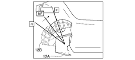
- FIG. 5 is a diagram for explaining the position of the bucket 12B controlled by the bucket position control section 13A of the ship control device 13 of the ship control device 13 of the second embodiment in the ship fixed point holding mode.
- the positions of the bucket 12B that can be placed by the bucket position control section 13A of the ship control device 13 when the ship control device 13 is in the ship fixed point holding mode are the neutral position N, the forward position F, and their A linear advance side intermediate position NF whose position can be linearly adjusted between is set. That is, the position of the bucket 12B that can be arranged by the bucket position control section 13A in the vessel fixed point holding mode of the vessel control device 13 includes a neutral position N, a forward position F, and a linearly adjustable forward position therebetween. intermediate positions NF.
- the vessel control device 13 controls the position of the bucket 12B (the bucket 12B is positioned at any of the neutral position N, the intermediate position NF on the linear advance side, and the forward position F). ) and the control of the rotation speed of the engine 11 are executed. Specifically, in the vessel fixed-point holding mode of the vessel control device 13, the vessel control device 13 sets the rotation speed of the engine 11 to a predetermined value so that the vessel 1 is held at the target vessel position. is set to any one of forward position F, neutral position N and linear forward intermediate position NF.
- Table 2 shows an example of the correspondence between the rotation speed of the engine 11, the position of the bucket 12B, and the like in the vessel fixed point holding mode of the vessel control device 13 of the vessel 1 of the second embodiment.
- the control amount (feedback control amount) calculated by the ship control device 13 when the deviation between the target ship position and the actual ship position is zero when the ship control device 13 is in the ship fixed-point holding mode. becomes zero.
- the bucket position controller 13A of the ship control device 13 places the bucket 12B at the neutral position N.
- the engine rotation speed control section 13B of the vessel control device 13 controls the rotation speed of the engine 11 to "IDLE" (the rotation speed of the engine 11 in the idling state).
- the jet propulsion device 12 does not generate a propulsive force for moving the ship 1, and the ship 1 is held at the target ship position.
- the deviation between the target ship position and the actual ship position in the ship fixed point holding mode of the ship control device 13 is "+1" (that is, the amount corresponding to the deviation "+1"
- the control amount calculated by the ship control device 13 becomes "+1".
- the bucket position control section 13A of the ship control device 13 arranges the bucket 12B at the intermediate position NF on the linear advance side.
- the bucket position control unit 13A adjusts the position of the bucket 12B to a position closer to the neutral position N in the intermediate position NF on the linear advance side. Further, the engine rotation speed control section 13B of the vessel control device 13 controls the rotation speed of the engine 11 to "IDLE". As a result, the jet propulsion device 12 generates a propulsion force for moving the ship 1 forward to reduce the deviation from "+1" to zero, and the ship 1 is held at the target ship position.
- the engine rotation speed control section 13B of the vessel control device 13 controls the rotation speed of the engine 11 to "IDLE".
- the jet propulsion device 12 generates a propulsive force for moving the ship 1 forward to reduce the deviation from "+2" to zero, and the ship 1 is held at the target ship position.
- the deviation between the target vessel position and the actual vessel position in the vessel fixed point holding mode of the vessel control device 13 is "+3"(>deviation"+2") (that is, deviation "+3 ), the control amount calculated by the ship control device 13 is "+3"(>control amount "+2"). )become.
- the bucket position control section 13A of the ship control device 13 arranges the bucket 12B at the intermediate position NF on the linear advance side. Specifically, the bucket position control unit 13A adjusts the position of the bucket 12B to a position closer to the forward position F in the linear forward side intermediate position NF. Further, the engine rotation speed control section 13B of the vessel control device 13 controls the rotation speed of the engine 11 to "IDLE". As a result, the jet propulsion device 12 generates a propulsion force for moving the ship 1 forward to reduce the deviation from "+3" to zero, and the ship 1 is held at the target ship position.
- the jet propulsion device 12 generates a propulsion force for moving the ship 1 forward to reduce the deviation from "+4" to zero, and the ship 1 is held at the target ship position.
- the control amount calculated by the ship control device 13 is "+5"(>control amount "+4"). )become.
- the bucket position control section 13A of the vessel control device 13 places the bucket 12B at the forward position F.
- the engine rotation speed control section 13B of the vessel control device 13 controls the rotation speed of the engine 11 to "IDLE+1"(>rotation speed of the engine 11 "IDLE”).
- the jet propulsion device 12 generates a propulsion force for moving the ship 1 forward to reduce the deviation from "+5" to zero, and the ship 1 is held at the target ship position.
- the control amount calculated by the ship control device 13 is "+6"(>control amount "+5"). )become.
- the bucket position control section 13A of the vessel control device 13 places the bucket 12B at the forward position F.
- the engine rotation speed control unit 13B of the vessel control device 13 controls the rotation speed of the engine 11 to "IDLE+2"(>rotation speed of the engine 11 "IDLE+1").
- the jet propulsion device 12 generates a propulsion force for moving the ship 1 forward to reduce the deviation from "+6" to zero, and the ship 1 is held at the target ship position.
- the actual vessel position may be positioned behind the target vessel position. If the position of the bucket 12B is set to the forward position F, the actual position of the ship would be positioned forward of the target position of the ship (that is, if a relatively small external force is applied to the ship 1 in the rearward direction). , the position of the bucket 12B is set to the linear advance side intermediate position NF, and the rotational speed of the engine 11 is set to "IDLE" so that the ship 1 is fixedly held at the target ship position.
- the linear advance side intermediate position NF is set as the position of the bucket 12B, and the position of the bucket 12B is controlled and the rotation speed of the engine 11 is changed during the vessel fixed point holding mode of the vessel control device 13. Since both of the controls are executed, for example, when the deviation between the target vessel position and the actual vessel position is "+1", "+2", or "+3", the bucket 12B is placed at the forward position F. It is possible to prevent the ship 1 from moving too far ahead of the target ship position.
- the rotation speed of the engine 11 is controlled to be "IDLE” when the position of the bucket 12B is set to the linear advance side intermediate position NF.
- the rotation speed of the engine 11 may be controlled to a rotation speed other than "IDLE” (for example, "IDLE+1", “IDLE+2”, etc.).
- the position of the bucket 12B is changed from a position near the neutral position N in the intermediate position NF on the linear advance side ⁇ a position between the neutral position N and the forward position F in the intermediate position NF on the linear advance side ⁇ linear
- the rotation speed of the engine 11 may be changed, for example, from "IDLE" ⁇ "IDLE+1" ⁇ "IDLE+2".
- a third embodiment of a ship, a ship control device, a ship control method, and a program according to the present invention will be described below.
- the ship 1 of the third embodiment is configured in the same manner as the ship 1 of the first embodiment described above, except for points to be described later. Therefore, according to the ship 1 of the third embodiment, the same effects as those of the ship 1 of the first embodiment described above can be obtained except for the points described later.
- the ship 1 of the third embodiment includes, for example, an engine 11, a jet propulsion device 12, a ship control device 13, a ship position detector 14, and an operation unit. 15.
- the bucket 12B of the jet propulsion device 12 of the ship 1 of the third embodiment is configured to be arranged at a forward position F, a neutral position N, and a reverse position R.
- the bucket position control unit 13A of the vessel control device 13 of the vessel 1 of the third embodiment controls the position of the bucket 12B (for example, control to place the bucket 12B at the forward position F, control to place the bucket 12B at the neutral position N, control to place the bucket 12B at the reverse position R, etc.).
- the engine rotation speed control section 13B of the boat control device 13 of the boat 1 of the third embodiment controls the rotation speed of the engine 11 (that is, the control for changing the strength of the jet shown in FIG. 2).
- the ship control device 13 of the ship 1 of the third embodiment not only has the normal mode but also the ship fixed point holding mode, like the ship control device 13 of the ship 1 of the first embodiment.
- the vessel control device 13 of the vessel 1 of the third embodiment in the vessel fixed point holding mode, controls the engine 11 and the Feedback control (for example, PID control) of the jet propulsion device 12 is executed.
- FIG. 6 is a diagram showing an example of the position of the bucket 12B controlled by the bucket position control section 13A of the ship control device 13 of the ship 1 of the third embodiment in the ship fixed point holding mode.
- the positions of the bucket 12B that can be arranged by the bucket position control section 13A of the ship control device 13 during the ship fixed point holding mode of the ship control device 13 are the neutral position N, the reverse position R, and their Three reverse side intermediate positions N-1, N-2, and N-3 are set therebetween.
- the positions of the bucket 12B that can be placed by the bucket position control section 13A in the vessel fixed point holding mode of the vessel control device 13 include the neutral position N, the reverse intermediate position N ⁇ 1, the backward intermediate position N ⁇ 2, A reverse intermediate position N-3 and a reverse position R are included.
- three reverse intermediate positions N-1, N-2, and N-3 are set as reverse intermediate positions between the neutral position N and the reverse position R.
- any number of reverse intermediate positions other than three may be set.
- the rotation angle ⁇ of the bucket 12B required to move the bucket 12B from the neutral position N to the reverse position R is divided into four. Further, the position where the bucket 12B is rotated by ( ⁇ /4) from the neutral position N is set as the backward intermediate position N ⁇ 1, and the bucket 12B is rotated by (2 ⁇ /4) from the neutral position N. The position is set as the reverse intermediate position N-2, and the position where the bucket 12B is rotated by (3 ⁇ /4) from the neutral position N is set as the reverse intermediate position N-3. In the example shown in FIG.
- the rotation angle ⁇ of the bucket 12B required to move the bucket 12B from the neutral position N to the reverse position R is divided at equal angular intervals, and the reverse intermediate positions N ⁇ 1 and N ⁇ 2 and N-3 are set, but in another example, the rotation angle of the bucket 12B required to move the bucket 12B from the neutral position N to the reverse intermediate position N-1 and the reverse intermediate position
- the pivoting angle of the bucket 12B required to move the bucket 12B from the reverse intermediate position N-3 to the reverse position R may be different from each other.
- the ship control device 13 controls the position of the bucket 12B (the bucket 12B is placed in the neutral position N, the reverse side intermediate positions N-1, N-2, N-3 and reverse position R), and control of the rotation speed of the engine 11 are executed. Specifically, in the vessel fixed-point holding mode of the vessel control device 13, the vessel control device 13 sets the rotation speed of the engine 11 to a predetermined value so that the vessel 1 is held at the target vessel position. is set to any one of the reverse position R, the neutral position N, and the three reverse side intermediate positions N-1, N-2 and N-3.
- Table 3 shows an example of the correspondence between the rotation speed of the engine 11, the position of the bucket 12B, and the like in the vessel fixed point holding mode of the vessel control device 13 of the vessel 1 of the third embodiment.
- the control amount (feedback control amount) calculated by the ship control device 13 when the deviation between the target ship position and the actual ship position is zero when the ship control device 13 is in the ship fixed-point holding mode. becomes zero.
- the bucket position controller 13A of the ship control device 13 places the bucket 12B at the neutral position N.
- the bucket position control unit 13A controls the position of the bucket 12B to the neutral position N even if the shift operation unit 15B does not accept the operator's input operation.
- the engine rotation speed control section 13B of the vessel control device 13 controls the rotation speed of the engine 11 to "IDLE” (the rotation speed of the engine 11 in the idling state). Specifically, the engine rotation speed control unit 13B controls the rotation speed of the engine 11 to "IDLE” even if the throttle operation unit 15A does not accept the input operation of the boat operator. Therefore, the jet propulsion device 12 does not generate a propulsive force for moving the ship 1, and the ship 1 is held at the target ship position.
- the bucket position control section 13A of the vessel control device 13 arranges the bucket 12B at the backward intermediate position N-1. Specifically, the bucket position control unit 13A controls the position of the bucket 12B to the reverse side intermediate position N ⁇ 1 even if the shift operation unit 15B does not accept the input operation of the operator.
- the engine rotation speed control section 13B of the vessel control device 13 controls the rotation speed of the engine 11 to "IDLE". Specifically, the engine rotation speed control unit 13B controls the rotation speed of the engine 11 to "IDLE” even if the throttle operation unit 15A does not accept the input operation of the boat operator. As a result, the jet propulsion device 12 generates a propulsive force to reverse the ship 1 to reduce the deviation from "-1" to zero, and the ship 1 is held at the target ship position.
- the bucket position control section 13A of the vessel control device 13 arranges the bucket 12B at the reverse intermediate position N-2. Specifically, the bucket position control unit 13A controls the position of the bucket 12B to the reverse side intermediate position N ⁇ 2 even if the shift operation unit 15B does not accept the input operation of the boat operator. Further, the engine rotation speed control section 13B of the vessel control device 13 controls the rotation speed of the engine 11 to "IDLE".
- the engine rotation speed control unit 13B controls the rotation speed of the engine 11 to "IDLE” even if the throttle operation unit 15A does not accept the input operation of the boat operator.
- the jet propulsion device 12 generates a propulsive force to reverse the ship 1 to reduce the deviation from "-2" to zero, and the ship 1 is held at the target ship position.
- Table 3 when the deviation between the target vessel position and the actual vessel position in the vessel fixed point holding mode of the vessel control device 13 is "-3" (that is, the amount corresponding to the deviation "-3" When the actual ship position deviates from the target ship position to the front side of the ship 1, the control amount calculated by the ship control device 13 becomes "-3".
- the bucket position control section 13A of the vessel control device 13 arranges the bucket 12B at the reverse intermediate position N-3. Specifically, the bucket position control unit 13A controls the position of the bucket 12B to the reverse side intermediate position N-3 even if the shift operation unit 15B does not accept the input operation of the operator. Further, the engine rotation speed control section 13B of the vessel control device 13 controls the rotation speed of the engine 11 to "IDLE". Specifically, the engine rotation speed control unit 13B controls the rotation speed of the engine 11 to "IDLE” even if the throttle operation unit 15A does not accept the input operation of the boat operator. As a result, the jet propulsion device 12 generates a propulsive force to reverse the ship 1 to reduce the deviation from "-3" to zero, and the ship 1 is held at the target ship position.
- the engine rotation speed control unit 13B controls the rotation speed of the engine 11 to "IDLE” even if the throttle operation unit 15A does not accept the input operation of the boat operator.
- the jet propulsion device 12 generates a propulsive force to reverse the ship 1 to reduce the deviation from "-4" to zero, and the ship 1 is held at the target ship position.
- Table 3 when the deviation between the target vessel position and the actual vessel position in the vessel fixed point holding mode of the vessel control device 13 is "-5" (that is, the amount corresponding to the deviation "-5" When the actual ship position deviates from the target ship position to the front side of the ship 1, the control amount calculated by the ship control device 13 becomes "-5".
- the bucket position control section 13A of the ship control device 13 places the bucket 12B at the reverse position R. Specifically, the bucket position control unit 13A controls the position of the bucket 12B to the reverse position R even if the shift operation unit 15B does not accept the operator's input operation. Further, the engine rotation speed control section 13B of the vessel control device 13 controls the rotation speed of the engine 11 to "IDLE+1"(>rotation speed of the engine 11 "IDLE”). Specifically, the engine rotation speed control unit 13B controls the rotation speed of the engine 11 to "IDLE+1" even if the throttle operation unit 15A does not receive the input operation of the boat operator.
- the jet propulsion device 12 generates a propulsive force to reverse the ship 1 to reduce the deviation from "-5" to zero, and the ship 1 is held at the target ship position. Furthermore, in the example shown in Table 3, when the deviation between the target vessel position and the actual vessel position in the vessel fixed point holding mode of the vessel control device 13 is "-6" (that is, the amount corresponding to the deviation "-6" When the actual ship position deviates from the target ship position to the front side of the ship 1, the control amount calculated by the ship control device 13 becomes "-6". As a result, the bucket position control section 13A of the ship control device 13 places the bucket 12B at the reverse position R.
- the bucket position control unit 13A controls the position of the bucket 12B to the reverse position R even if the shift operation unit 15B does not accept the operator's input operation.
- the engine rotation speed control unit 13B of the vessel control device 13 controls the rotation speed of the engine 11 to "IDLE+2"(>rotation speed of the engine 11 "IDLE+1").
- the engine rotation speed control unit 13B controls the rotation speed of the engine 11 to "IDLE+2" even if the throttle operation unit 15A does not accept the input operation of the boat operator.
- the jet propulsion device 12 generates a propulsive force to reverse the ship 1 to reduce the deviation from "-6" to zero, and the ship 1 is held at the target ship position.
- the position of the bucket 12B is set to the neutral position N when the vessel control device 13 is in the vessel fixed point holding mode, the actual vessel position will be positioned forward of the target vessel position. Therefore, if the position of the bucket 12B is set to the reverse position R, the actual position of the ship will be positioned behind the target position of the ship (that is, if a relatively small forward external force is applied to the ship 1). , the position of the bucket 12B is set to, for example, the reverse side intermediate position N-1, the reverse side intermediate position N-2, the reverse side intermediate position N-3, etc., and the vessel 1 is held at a fixed point at the target vessel position. , the rotational speed of the engine 11 is set to "IDLE".
- the backward intermediate positions N-1, N-2, and N-3 are set as the position of the bucket 12B, and the position of the bucket 12B is and the rotational speed control of the engine 11 are both executed. is arranged at the reverse position R, the ship 1 can be prevented from moving too far rearward from the target ship position.
- the bucket it is possible to improve the controllability of keeping the vessel at a fixed point as compared with the case where both the control of the position of 12B and the control of the rotational speed of the engine 11 are not executed.
- the rotational speed of the engine 11 is controlled to "IDLE" when the position of the bucket 12B is set to the intermediate positions N-1, N-2, N-3 on the reverse side.
- the rotation speed of the engine 11 is set to a rotation speed other than “IDLE” (for example, “IDLE+1”, “IDLE+2”). ”, etc.).
- the rotational speed of the engine 11 is, for example, "IDLE”. ⁇ "IDLE+1" ⁇ "IDLE+2".
- FIG. 7 is a flowchart for explaining an example of processing executed by the ship control device 13 of the ship 1 of the third embodiment.
- the vessel control device 13 determines whether or not the vessel fixed-point maintenance mode is set (determines whether the vessel fixed-point maintenance mode or the normal mode is selected).
- the process proceeds to step S31, and when the ship control device 13 is in the normal mode, the process proceeds to step S32.
- step S31 the vessel control device 13 performs feedback control of the engine 11 and the jet propulsion device 12 based on the deviation between the target vessel position and the actual vessel position.
- the ship control device 13 executes control to hold the ship 1 at the target ship position (executes holding the ship 1 at a fixed point).
- the bucket position control section 13A of the vessel control device 13 controls the position of the bucket 12B.
- the positions of the bucket 12B include the neutral position N, the reverse position R, and the reverse intermediate positions N-1, N-2, and N-3.
- the engine rotation speed control section 13B of the vessel control device 13 controls the rotation speed of the engine 11. FIG. That is, when step S31 is executed, both the position control of the bucket 12B including the reverse intermediate positions N-1, N-2 and N-3 and the rotational speed control of the engine 11 are executed.
- step S32 the ship control device 13 executes normal mode control. Specifically, the bucket position control unit 13A controls the position of the bucket 12B to any one of the forward position F, the neutral position N, and the reverse position R based on the operator's input operation received by the shift operation unit 15B. . Further, the engine rotation speed control section 13B controls the rotation speed of the engine 11 based on the operator's input operation received by the throttle operation section 15A.
- a fourth embodiment of a ship, a ship control device, a ship control method, and a program according to the present invention will be described below.
- the ship 1 of the fourth embodiment is configured in the same manner as the ship 1 of the first embodiment described above, except for the points described later. Therefore, according to the ship 1 of the fourth embodiment, the same effects as those of the ship 1 of the first embodiment described above can be obtained except for the points described later.
- the ship 1 of the fourth embodiment includes, for example, an engine 11, a jet propulsion device 12, a ship control device 13, a ship position detector 14, and an operation unit. 15.
- the bucket 12B of the jet propulsion device 12 of the ship 1 of the fourth embodiment is configured to be arranged at a forward position F, a neutral position N, and a reverse position R.
- the bucket position control unit 13A of the vessel control device 13 of the vessel 1 of the fourth embodiment controls the position of the bucket 12B (for example, control to place the bucket 12B at the forward position F, control to place the bucket 12B at the neutral position N, control to place the bucket 12B at the reverse position R, etc.).
- the engine rotation speed control unit 13B of the boat control device 13 of the boat 1 of the fourth embodiment controls the rotation speed of the engine 11 (that is, the control for changing the strength of the jet shown in FIG. 2).
- the ship control device 13 of the ship 1 of the fourth embodiment not only has the normal mode but also the ship fixed point holding mode, like the ship control device 13 of the ship 1 of the first embodiment.
- the vessel control device 13 of the vessel 1 of the fourth embodiment in the vessel fixed point holding mode, controls the engine 11 and the Feedback control (for example, PID control) of the jet propulsion device 12 is performed.
- FIG. 8 is a diagram for explaining the position of the bucket 12B controlled by the bucket position control section 13A of the ship control device 13 of the ship control device 13 of the fourth embodiment in the ship fixed point holding mode.
- the positions of the bucket 12B that can be arranged by the bucket position control section 13A of the ship control device 13 when the ship control device 13 is in the ship fixed point holding mode are the neutral position N, the reverse position R, and their A linear reverse side intermediate position NR whose position is linearly adjustable between is set. That is, the position of the bucket 12B that can be arranged by the bucket position control section 13A in the vessel fixed point holding mode of the vessel control device 13 includes a neutral position N, a reverse position R, and a linearly adjustable reverse position therebetween. intermediate position NR.
- the vessel control device 13 controls the position of the bucket 12B (the bucket 12B is positioned at any of the neutral position N, the linear reverse side intermediate position NR, and the reverse position R). control) and control of the rotation speed of the engine 11 are executed. More specifically, in the vessel fixed-point holding mode of the vessel control device 13, the vessel control device 13 sets the rotation speed of the engine 11 to a predetermined value so that the vessel 1 is held at the target vessel position. is set to any of the reverse position R, the neutral position N, and the linear reverse intermediate position NR.
- Table 4 shows an example of the correspondence between the rotation speed of the engine 11, the position of the bucket 12B, etc. in the vessel fixed point holding mode of the vessel control device 13 of the vessel 1 of the fourth embodiment.
- the control amount (feedback control amount) calculated by the ship control device 13 when the deviation between the target ship position and the actual ship position when the ship control device 13 is in the ship fixed point holding mode is zero. becomes zero.
- the bucket position control section 13A of the ship control device 13 places the bucket 12B at the neutral position N.
- the engine rotation speed control section 13B of the vessel control device 13 controls the rotation speed of the engine 11 to "IDLE" (the rotation speed of the engine 11 in the idling state).
- the jet propulsion device 12 does not generate a propulsive force for moving the ship 1, and the ship 1 is held at the target ship position.
- the deviation between the target vessel position and the actual vessel position in the vessel fixed point holding mode of the vessel control device 13 is "-1" (that is, the amount corresponding to the deviation "-1"
- the control amount calculated by the ship control device 13 becomes "-1".
- the bucket position control section 13A of the ship control device 13 arranges the bucket 12B at the linear backward intermediate position NR.
- the bucket position control unit 13A adjusts the position of the bucket 12B to a position closer to the neutral position N of the linear reverse side intermediate positions NR. Further, the engine rotation speed control section 13B of the vessel control device 13 controls the rotation speed of the engine 11 to "IDLE". As a result, the jet propulsion device 12 generates a propulsive force to reverse the ship 1 to reduce the deviation from "-1" to zero, and the ship 1 is held at the target ship position.
- the bucket position control section 13A of the ship control device 13 arranges the bucket 12B at the linear backward intermediate position NR. Specifically, the bucket position control unit 13A adjusts the position of the bucket 12B to a position between the neutral position N and the reverse position R of the linear reverse side intermediate position NR. Further, the engine rotation speed control section 13B of the vessel control device 13 controls the rotation speed of the engine 11 to "IDLE".
- the jet propulsion device 12 generates a propulsive force to reverse the ship 1 to reduce the deviation from "-2" to zero, and the ship 1 is held at the target ship position.
- the deviation between the target vessel position and the actual vessel position in the vessel fixed point holding mode of the vessel control device 13 is "-3" (that is, the amount corresponding to the deviation "-3"
- the control amount calculated by the ship control device 13 becomes "-3".
- the bucket position control section 13A of the ship control device 13 arranges the bucket 12B at the linear backward intermediate position NR.
- the bucket position control unit 13A adjusts the position of the bucket 12B to a position closer to the reverse position R among the linear reverse side intermediate positions NR. Further, the engine rotation speed control section 13B of the vessel control device 13 controls the rotation speed of the engine 11 to "IDLE". As a result, the jet propulsion device 12 generates a propulsive force to reverse the ship 1 to reduce the deviation from "-3" to zero, and the ship 1 is held at the target ship position.
- the jet propulsion device 12 generates a propulsive force to move the ship 1 forward to reduce the deviation from "-5" to zero, and the ship 1 is held at the target ship position. Furthermore, in the example shown in Table 4, when the deviation between the target vessel position and the actual vessel position in the vessel fixed point holding mode of the vessel control device 13 is "-6" (that is, the amount corresponding to the deviation "-6" When the actual ship position deviates from the target ship position to the front side of the ship 1, the control amount calculated by the ship control device 13 becomes "-6". As a result, the bucket position control section 13A of the ship control device 13 places the bucket 12B at the reverse position R.
- the engine rotation speed control unit 13B of the vessel control device 13 controls the rotation speed of the engine 11 to "IDLE+2"(>rotation speed of the engine 11 "IDLE+1").
- the jet propulsion device 12 generates a propulsive force to reverse the ship 1 to reduce the deviation from "-6" to zero, and the ship 1 is held at the target ship position.
- the position of the bucket 12B is set to the neutral position N when the ship control device 13 is in the ship fixed point holding mode, the actual ship position will be positioned forward of the target ship position. Therefore, if the position of the bucket 12B is set to the reverse position R, the actual position of the ship will be positioned behind the target position of the ship (that is, if a relatively small forward external force is applied to the ship 1). , the position of the bucket 12B is set to the linear reverse side intermediate position NR, and the rotational speed of the engine 11 is set to "IDLE" so that the ship 1 is fixedly held at the target ship position.
- the linear backward intermediate position NR is set as the position of the bucket 12B, and the position of the bucket 12B is controlled and the rotation speed of the engine 11 is changed during the vessel fixed point holding mode of the vessel control device 13. Since both controls are executed, the bucket 12B is placed at the reverse position R when the deviation between the target vessel position and the actual vessel position is "-1", "-2", or "-3". It is possible to prevent the ship 1 from excessively moving to the rear side of the target ship position. That is, in the ship 1 of the fourth embodiment, when the linear reverse side intermediate position NR is not set as the position of the bucket 12B, or when the ship control device 13 is in the ship fixed point holding mode, the position of the bucket 12B is controlled and the engine 11 is operated. It is possible to improve the controllability of keeping the vessel at a fixed point, compared to when both the rotation speed control is not executed.
- the rotation speed of the engine 11 is controlled to be "IDLE” when the position of the bucket 12B is set to the linear backward intermediate position NR.
- the rotation speed of the engine 11 may be controlled to a rotation speed other than "IDLE” (for example, “IDLE+1", “IDLE+2”, etc.) when set to the reverse side intermediate position NR.
- the position of the bucket 12B is changed from a position near the neutral position N among the linear reverse-side intermediate positions NR ⁇ a position between the neutral position N and the reverse position R among the linear reverse-side intermediate positions NR ⁇ linear
- the rotational speed of the engine 11 may be changed, for example, from "IDLE" ⁇ "IDLE+1" ⁇ "IDLE+2".
- a fifth embodiment of a ship, a ship control device, a ship control method, and a program according to the present invention will be described below.
- the ship 1 of the fifth embodiment is configured in the same manner as the ship 1 of the first embodiment described above, except for the points described later. Therefore, according to the ship 1 of the fifth embodiment, the same effects as those of the ship 1 of the first embodiment described above can be obtained except for the points described later.
- the ship 1 of the fifth embodiment includes, for example, an engine 11, a jet propulsion device 12, a ship control device 13, a ship position detector 14, and an operation unit. 15.
- the bucket 12B of the jet propulsion device 12 of the vessel 1 of the fifth embodiment is configured to be arranged at a forward position F, a neutral position N, and a reverse position R.
- the bucket position control unit 13A of the vessel control device 13 of the vessel 1 of the fifth embodiment controls the position of the bucket 12B (for example, control to place the bucket 12B at the forward position F, control to place the bucket 12B at the neutral position N, control to place the bucket 12B at the reverse position R, etc.).
- the engine rotation speed control unit 13B of the boat control device 13 of the boat 1 of the fifth embodiment controls the rotation speed of the engine 11 (that is, the control for changing the strength of the jet shown in FIG. 2).
- the vessel control device 13 for the vessel 1 of the fifth embodiment not only has the normal mode but also the vessel fixed point holding mode, like the vessel control device 13 for the vessel 1 of the first embodiment. Further, the vessel control device 13 of the vessel 1 of the fifth embodiment, in the vessel fixed point holding mode, controls the engine 11 and the Feedback control (for example, PID control) of the jet propulsion device 12 is performed.
- the position of the bucket 12B that can be arranged by the bucket position controller 13A of the boat controller 13 in the boat fixed-point holding mode of the boat controller 13 is a forward position F (see FIG. 3), A neutral position N (see FIGS. 3 and 6), three forward intermediate positions N+1, N+2, and N+3 (see FIG. 3) located therebetween, a reverse position R (see FIG. 6), and a neutral position N and the reverse position R, three reverse intermediate positions N-1, N-2, and N-3 (see FIG. 6) are set.
- three forward intermediate positions N+1, N+2, and N+3 are set as forward intermediate positions between the neutral position N and the forward position F.
- any number of forward intermediate positions other than three are set as forward intermediate positions between the neutral position N and the forward position F. good.
- three reverse intermediate positions N ⁇ 1, N ⁇ 2, N ⁇ 3 is set, but in another example of the boat 1 of the fifth embodiment, any number of reverse intermediate positions other than 3 is used as the reverse intermediate position between the neutral position N and the reverse position R. may be set.
- the rotation angle ⁇ of the bucket 12B required to move the bucket 12B from the neutral position N to the forward position F is divided into four. Further, the position where the bucket 12B is rotated by ( ⁇ /4) from the neutral position N is set as the forward side intermediate position N+1, and the position where the bucket 12B is rotated by (2 ⁇ /4) from the neutral position N is , and the position where the bucket 12B is rotated by (3 ⁇ /4) from the neutral position N is set as the forward intermediate position N+3.
- the ship 1 of the fifth embodiment the example shown in FIG.
- the bucket 12B required to move the bucket 12B from the neutral position N to the forward intermediate position N+1 is set to the rotation angle of the bucket 12B, the rotation angle of the bucket 12B required to move the bucket 12B from the forward intermediate position N+1 to the forward intermediate position N+2, and the bucket 12B from the forward intermediate position N+2 to the forward intermediate position N+3. may be different from each other.
- the rotation angle ⁇ of the bucket 12B required to move the bucket 12B from the neutral position N to the reverse position R is divided into four. Further, the position where the bucket 12B is rotated by ( ⁇ /4) from the neutral position N is set as the backward intermediate position N ⁇ 1, and the bucket 12B is rotated by (2 ⁇ /4) from the neutral position N. The position is set as the reverse intermediate position N-2, and the position where the bucket 12B is rotated by (3 ⁇ /4) from the neutral position N is set as the reverse intermediate position N-3.
- the example of the boat 1 of the fifth embodiment the example shown in FIG.
- the rotation angle ⁇ of the bucket 12B required to move the bucket 12B from the neutral position N to the reverse position R is divided at equal angular intervals.
- the bucket 12B is moved from the neutral position N to the reverse intermediate position N-1.
- the rotation angle of the bucket 12B required to move the bucket 12B from the reverse side intermediate position N-1 to the reverse side intermediate position N-2, and the reverse side The rotation angle of the bucket 12B required to move the bucket 12B from the intermediate position N-2 to the reverse side intermediate position N-3, and the rotation angle of the bucket 12B required to move the bucket 12B from the reverse side intermediate position N-3 to the reverse position R
- the required rotation angle of the bucket 12B may be different from each other.
- the boat controller 13 controls the position of the bucket 12B (the bucket 12B is moved to the forward position F, forward intermediate positions N+1, N+2, N+3, neutral position N, intermediate positions N-1, N-2, N-3 on the reverse side, and reverse position R), and control of the rotation speed of the engine 11 are executed.
- the vessel control device 13 sets the rotation speed of the engine 11 to a predetermined value so that the vessel 1 is held at the target vessel position. is set to any of forward position F, three forward intermediate positions N+1, N+2, N+3, neutral position N, three reverse intermediate positions N-1, N-2, N-3 and reverse position R. Execute control.
- Table 5 shows an example of the correspondence between the rotation speed of the engine 11, the position of the bucket 12B, and the like when the ship control device 13 is in the ship fixed point holding mode.
- Table 5 shows an example of the correspondence between the rotation speed of the engine 11, the position of the bucket 12B, and the like when the ship control device 13 is in the ship fixed point holding mode.
- the deviation between the target vessel position and the actual vessel position in the vessel fixed point holding mode of the vessel control device 13 is "-6" (that is, the amount corresponding to the deviation "-6"
- the control amount calculated by the ship control device 13 is "-6".
- the bucket position control section 13A of the ship control device 13 places the bucket 12B at the reverse position R.
- the engine rotation speed control section 13B of the vessel control device 13 controls the rotation speed of the engine 11 to "IDLE+2".
- the jet propulsion device 12 generates a propulsive force to reverse the ship 1 to reduce the deviation from "-6" to zero, and the ship 1 is held at the target ship position.
- the deviation between the target vessel position and the actual vessel position in the vessel fixed point holding mode of the vessel control device 13 is "-5" (that is, the amount corresponding to the deviation "-5"
- the control amount calculated by the ship control device 13 becomes "-5".
- the bucket position control section 13A of the ship control device 13 places the bucket 12B at the reverse position R.
- the engine rotation speed control section 13B of the vessel control device 13 controls the rotation speed of the engine 11 to "IDLE+1".
- the jet propulsion device 12 generates a propulsive force to reverse the ship 1 to reduce the deviation from "-5" to zero, and the ship 1 is held at the target ship position.
- the deviation between the target vessel position and the actual vessel position in the vessel fixed-point holding mode of the vessel control device 13 is "-4" (that is, the amount corresponding to the deviation "-4"
- the control amount calculated by the ship control device 13 becomes "-4".
- the bucket position control section 13A of the ship control device 13 places the bucket 12B at the reverse position R.
- the engine rotation speed control section 13B of the vessel control device 13 controls the rotation speed of the engine 11 to "IDLE".
- the jet propulsion device 12 generates a propulsive force to reverse the ship 1 to reduce the deviation from "-4" to zero, and the ship 1 is held at the target ship position.
- the jet propulsion device 12 generates a propulsive force to reverse the ship 1 to reduce the deviation from "-3" to zero, and the ship 1 is held at the target ship position.
- the deviation between the target vessel position and the actual vessel position in the vessel fixed point holding mode of the vessel control device 13 is "-2" (that is, the amount corresponding to the deviation "-2"
- the control amount calculated by the ship control device 13 becomes "-2".
- the bucket position control section 13A of the vessel control device 13 arranges the bucket 12B at the reverse intermediate position N-2.
- the engine rotation speed control section 13B of the vessel control device 13 controls the rotation speed of the engine 11 to "IDLE".
- the jet propulsion device 12 generates a propulsive force to reverse the ship 1 to reduce the deviation from "-2" to zero, and the ship 1 is held at the target ship position.
- the control amount (feedback control amount) calculated by the ship control device 13 when the deviation between the target ship position and the actual ship position is zero when the ship control device 13 is in the ship fixed-point holding mode. becomes zero.
- the bucket position control section 13A of the ship control device 13 places the bucket 12B at the neutral position N.
- the engine rotation speed control section 13B of the vessel control device 13 controls the rotation speed of the engine 11 to "IDLE" (the rotation speed of the engine 11 in the idling state). Therefore, the jet propulsion device 12 does not generate a propulsive force for moving the ship 1, and the ship 1 is held at the target ship position.
- the engine rotation speed control unit 13B controls the rotation speed of the engine 11 to "IDLE+1" even if the throttle operation unit 15A does not receive the input operation of the boat operator.
- the jet propulsion device 12 generates a propulsion force for moving the ship 1 forward to reduce the deviation from "+5" to zero, and the ship 1 is held at the target ship position.
- the control amount calculated by the ship control device 13 becomes "+6".
- the bucket position control section 13A of the ship control device 13 places the bucket 12B at the forward position F.
- the engine rotation speed control section 13B of the vessel control device 13 controls the rotation speed of the engine 11 to "IDLE+2".
- the jet propulsion device 12 generates a propulsion force for moving the ship 1 forward to reduce the deviation from "+6" to zero, and the ship 1 is held at the target ship position.
- the position of the bucket 12B is set to the neutral position N when the vessel control device 13 is in the vessel fixed point holding mode, the actual vessel position may be positioned behind the target vessel position. If the position of the bucket 12B is set to the forward travel position F, the actual position of the ship would be positioned forward of the target position of the ship (that is, the case where a relatively small rearward external force is applied to the ship 1). Then, the position of the bucket 12B is set to, for example, forward-side intermediate position N+1, forward-side intermediate position N+2, forward-side intermediate position N+3, etc., and the engine 11 is rotated so that the ship 1 is held at the target ship position at a fixed point. Speed is set to "IDLE".
- the position of the bucket 12B is set to the neutral position N in the vessel fixed point holding mode of the vessel control device 13, the actual vessel position will be positioned forward of the target vessel position.
- the position of the bucket 12B is set to the reverse position R, the actual position of the ship will be positioned behind the target position of the ship (that is, a relatively small forward external force will be applied to the ship 1).
- the position of the bucket 12B is set to, for example, the reverse side intermediate position N-1, the reverse side intermediate position N-2, the reverse side intermediate position N-3, etc., and the vessel 1 is held at the target vessel position at a fixed point.
- the rotational speed of the engine 11 is set to "IDLE".
- forward side intermediate positions N+1, N+2, and N+3 and rearward side intermediate positions N ⁇ 1, N ⁇ 2, and N ⁇ 3 are set as the positions of the bucket 12B. Since both the control of the position of the bucket 12B and the control of the rotational speed of the engine 11 are executed in the vessel fixed point holding mode, the deviation between the target vessel position and the actual vessel position is "+1", "+2", "+3", for example. , it is possible to prevent the ship 1 from moving too far ahead of the target ship position due to the bucket 12B being placed at the forward position F.
- the target ship position and the actual ship position When the deviation is "-1", “-2”, or "-3", the ship 1 moves too far behind the target ship position as the bucket 12B is placed at the reverse position R. can be suppressed. That is, in the boat 1 of the fifth embodiment, when the forward intermediate positions N+1, N+2, and N+3 are not set as the positions of the bucket 12B, or when the backward intermediate positions N ⁇ 1, N ⁇ 2, The controllability of keeping the ship at a fixed point is better than when N-3 is not set or when both the control of the position of the bucket 12B and the control of the rotation speed of the engine 11 are not executed when the ship control device 13 is in the ship fixed point keeping mode. can be improved.
- the rotation speed of the engine 11 is controlled to "IDLE” when the position of the bucket 12B is set to the forward intermediate positions N+1, N+2, and N+3.
- the rotation speed of the engine 11 may be controlled to a rotation speed other than "IDLE” (for example, “IDLE+1", “IDLE+2”, etc.) when the positions are set to the forward intermediate positions N+1, N+2, N+3.
- the rotation speed of the engine 11 changes, for example, from "IDLE" ⁇ "IDLE+1" ⁇ "IDLE+2".
- the rotation speed of the engine 11 is controlled to "IDLE".
- the rotation speed of the engine 11 is a rotation speed other than “IDLE” (for example, “IDLE+1”, “IDLE+2", etc.).
- the rotational speed of the engine 11 is, for example, "IDLE”. ⁇ "IDLE+1" ⁇ "IDLE+2".
- FIG. 9 is a flow chart for explaining an example of processing executed by the ship control device 13 of the ship 1 of the fifth embodiment.
- the vessel control device 13 determines whether or not the vessel fixed-point maintenance mode is set (determines whether the vessel fixed-point maintenance mode or the normal mode is selected).
- the process proceeds to step S51, and when the ship control device 13 is in the normal mode, the process proceeds to step S52.
- step S51 the vessel control device 13 performs feedback control of the engine 11 and the jet propulsion device 12 based on the deviation between the target vessel position and the actual vessel position.
- the ship control device 13 executes control to hold the ship 1 at the target ship position (executes holding the ship 1 at a fixed point).
- the bucket position control section 13A of the ship control device 13 controls the position of the bucket 12B.
- the position of the bucket 12B includes forward position F, forward intermediate positions N+1, N+2, N+3, neutral position N, reverse position R and reverse intermediate positions N ⁇ 1, N ⁇ 2, N -3 included.
- the engine rotation speed control section 13B of the vessel control device 13 controls the rotation speed of the engine 11.
- step S51 when step S51 is executed, the positions of the bucket 12B including the forward side intermediate positions N+1, N+2, N+3 and the reverse side intermediate positions N ⁇ 1, N ⁇ 2, N ⁇ 3 are controlled, and the rotational speed of the engine 11 is increased. Both controls are executed.
- the ship control device 13 executes normal mode control. Specifically, the bucket position control unit 13A controls the position of the bucket 12B to any one of the forward position F, the neutral position N, and the reverse position R based on the operator's input operation received by the shift operation unit 15B. . Further, the engine rotation speed control section 13B controls the rotation speed of the engine 11 based on the operator's input operation received by the throttle operation section 15A.
- ⁇ Sixth embodiment> A sixth embodiment of a ship, a ship control device, a ship control method, and a program according to the present invention will be described below.
- the ship 1 of the sixth embodiment is configured in the same manner as the ship 1 of the first embodiment described above, except for the points described later. Therefore, according to the ship 1 of 6th Embodiment, the effect similar to the ship 1 of 1st Embodiment mentioned above can be produced except the point mentioned later.
- the ship 1 of the sixth embodiment includes, for example, an engine 11, a jet propulsion device 12, a ship control device 13, a ship position detector 14, and an operation unit. 15.
- the bucket 12B of the jet propulsion device 12 of the vessel 1 of the sixth embodiment is configured to be arranged at a forward position F, a neutral position N, and a reverse position R.
- the bucket position control unit 13A of the vessel control device 13 of the vessel 1 of the sixth embodiment controls the position of the bucket 12B (for example, control to place the bucket 12B at the forward position F, control to place the bucket 12B at the neutral position N, control to place the bucket 12B at the reverse position R, etc.).
- the engine rotation speed control section 13B of the boat control device 13 of the boat 1 of the sixth embodiment controls the rotation speed of the engine 11 (that is, the control for changing the strength of the jet shown in FIG. 2).
- the ship control device 13 of the ship 1 of the sixth embodiment not only has the normal mode but also the ship fixed point holding mode, like the ship control device 13 of the ship 1 of the first embodiment.
- the vessel control device 13 of the vessel 1 of the sixth embodiment in the vessel fixed-point holding mode, controls the engine 11 and the Feedback control (for example, PID control) of the jet propulsion device 12 is executed.
- the positions of the bucket 12B that can be arranged by the bucket position control section 13A of the ship control device 13 during the ship fixed point holding mode of the ship control device 13 are the forward position F (see FIG. 5), A neutral position N (see FIGS. 5 and 8), a linearly adjustable forward intermediate position NF (see FIG. 5) therebetween, a reverse position R (see FIG. 8), and a neutral position N
- a linear reverse intermediate position NR (see FIG. 8) that is linearly adjustable with the reverse position R is set.
- the positions of the bucket 12B that can be arranged by the bucket position control section 13A in the vessel fixed point holding mode of the vessel control device 13 include the forward position F, the neutral position N, the intermediate position NF on the linear forward side therebetween, and the reverse position.
- a position R and a linear reverse intermediate position NR between the neutral position N and the reverse position R are included.
- the ship control device 13 controls the position of the bucket 12B (the bucket 12B is moved to the forward position F, the linear forward side intermediate position NF, and the neutral position N). , linear reverse side intermediate position NR and reverse position R), and control of the rotation speed of the engine 11 are executed. Specifically, in the vessel fixed-point holding mode of the vessel control device 13, the vessel control device 13 sets the rotation speed of the engine 11 to a predetermined value so that the vessel 1 is held at the target vessel position. is set to any one of forward position F, linear forward intermediate position NF, neutral position N, linear reverse intermediate position NR and reverse position R.
- Table 6 shows an example of the correspondence between the rotation speed of the engine 11, the position of the bucket 12B, and the like in the vessel fixed point holding mode of the vessel control device 13 of the vessel 1 of the sixth embodiment.
- a propulsive force is generated to hold the vessel 1 at the target vessel position.
- the deviation between the target vessel position and the actual vessel position in the vessel fixed point holding mode of the vessel control device 13 is "-5" (that is, the amount corresponding to the deviation "-5"
- the control amount calculated by the ship control device 13 becomes "-5".
- the bucket position control section 13A of the ship control device 13 places the bucket 12B at the reverse position R.
- the engine rotation speed control section 13B of the vessel control device 13 controls the rotation speed of the engine 11 to "IDLE+1".
- the jet propulsion device 12 generates a propulsive force to move the ship 1 forward to reduce the deviation from "-5" to zero, and the ship 1 is held at the target ship position. Furthermore, in the example shown in Table 6, when the deviation between the target vessel position and the actual vessel position in the vessel fixed point holding mode of the vessel control device 13 is "-4" (that is, the amount corresponding to the deviation "-4" When the actual ship position deviates forward of the ship 1 from the target ship position by only 1, the control amount calculated by the ship control device 13 becomes "-4". As a result, the bucket position control section 13A of the ship control device 13 places the bucket 12B at the reverse position R.
- the engine rotation speed control section 13B of the vessel control device 13 controls the rotation speed of the engine 11 to "IDLE".
- the jet propulsion device 12 generates a propulsive force to reverse the ship 1 to reduce the deviation from "-4" to zero, and the ship 1 is held at the target ship position.
- the bucket position control section 13A of the ship control device 13 arranges the bucket 12B at the linear backward intermediate position NR. Specifically, the bucket position control unit 13A adjusts the position of the bucket 12B to a position closer to the reverse position R among the linear reverse side intermediate positions NR. Further, the engine rotation speed control section 13B of the vessel control device 13 controls the rotation speed of the engine 11 to "IDLE".
- the jet propulsion device 12 generates a propulsive force to reverse the ship 1 to reduce the deviation from "-3" to zero, and the ship 1 is held at the target ship position.
- the deviation between the target vessel position and the actual vessel position in the vessel fixed point holding mode of the vessel control device 13 is "-2" (that is, the amount corresponding to the deviation "-2"
- the control amount calculated by the ship control device 13 becomes "-2".
- the bucket position control section 13A of the ship control device 13 arranges the bucket 12B at the linear backward intermediate position NR.
- the bucket position control unit 13A adjusts the position of the bucket 12B to a position between the neutral position N and the reverse position R of the linear reverse side intermediate position NR. Further, the engine rotation speed control section 13B of the vessel control device 13 controls the rotation speed of the engine 11 to "IDLE". As a result, the jet propulsion device 12 generates a propulsive force to reverse the ship 1 to reduce the deviation from "-2" to zero, and the ship 1 is held at the target ship position.
- the bucket position control section 13A of the ship control device 13 arranges the bucket 12B at the linear backward intermediate position NR. Specifically, the bucket position control unit 13A adjusts the position of the bucket 12B to a position closer to the neutral position N of the linear reverse side intermediate positions NR. Further, the engine rotation speed control section 13B of the vessel control device 13 controls the rotation speed of the engine 11 to "IDLE".
- the jet propulsion device 12 generates a propulsive force to reverse the ship 1 to reduce the deviation from "-1" to zero, and the ship 1 is held at the target ship position.
- the control amount calculated by the ship control device 13 becomes zero.
- the bucket position control section 13A of the ship control device 13 places the bucket 12B at the neutral position N.
- the engine rotation speed control section 13B of the vessel control device 13 controls the rotation speed of the engine 11 to "IDLE". Therefore, the jet propulsion device 12 does not generate a propulsive force for moving the ship 1, and the ship 1 is held at the target ship position.
- the control amount calculated by the ship control device 13 becomes "+1".
- the bucket position control section 13A of the ship control device 13 arranges the bucket 12B at the intermediate position NF on the linear advance side.
- the bucket position control unit 13A adjusts the position of the bucket 12B to a position closer to the neutral position N in the intermediate position NF on the linear advance side.
- the engine rotation speed control section 13B of the vessel control device 13 controls the rotation speed of the engine 11 to "IDLE".
- the jet propulsion device 12 generates a propulsion force for moving the ship 1 forward to reduce the deviation from "+1" to zero, and the ship 1 is held at the target ship position.
- the control amount calculated by the ship control device 13 becomes "+2".
- the bucket position control section 13A of the ship control device 13 arranges the bucket 12B at the intermediate position NF on the linear advance side. Specifically, the bucket position control unit 13A adjusts the position of the bucket 12B to a position between the neutral position N and the forward position F of the linear forward intermediate positions NF. Further, the engine rotation speed control section 13B of the vessel control device 13 controls the rotation speed of the engine 11 to "IDLE".
- the jet propulsion device 12 generates a propulsive force for moving the ship 1 forward to reduce the deviation from "+2" to zero, and the ship 1 is held at the target ship position.
- the deviation between the target ship position and the actual ship position in the ship fixed point holding mode of the ship control device 13 is "+3" (that is, the amount corresponding to the deviation "+3"
- the control amount calculated by the ship control device 13 becomes "+3".
- the bucket position control section 13A of the ship control device 13 arranges the bucket 12B at the intermediate position NF on the linear advance side.
- the bucket position control unit 13A adjusts the position of the bucket 12B to a position closer to the forward position F in the linear forward side intermediate position NF. Further, the engine rotation speed control section 13B of the vessel control device 13 controls the rotation speed of the engine 11 to "IDLE". As a result, the jet propulsion device 12 generates a propulsion force for moving the ship 1 forward to reduce the deviation from "+3" to zero, and the ship 1 is held at the target ship position.
- the jet propulsion device 12 generates a propulsion force for moving the ship 1 forward to reduce the deviation from "+5" to zero, and the ship 1 is held at the target ship position. Furthermore, in the example shown in Table 6, when the deviation between the target vessel position and the actual vessel position in the vessel fixed point holding mode of the vessel control device 13 is "+6" (that is, the amount corresponding to the deviation "+6" When the actual ship position is shifted to the rear side of the ship 1 from the target ship position), the control amount calculated by the ship control device 13 becomes "+6". As a result, the bucket position control section 13A of the ship control device 13 places the bucket 12B at the forward position F.
- the engine rotation speed control section 13B of the vessel control device 13 controls the rotation speed of the engine 11 to "IDLE+2".
- the jet propulsion device 12 generates a propulsion force for moving the ship 1 forward to reduce the deviation from "+6" to zero, and the ship 1 is held at the target ship position.
- the actual vessel position may be located behind the target vessel position. If the position of the bucket 12B is set to the forward position F, the actual position of the ship would be positioned forward of the target position of the ship (that is, if a relatively small external force is applied to the ship 1 in the rearward direction). , the position of the bucket 12B is set to the linear advance side intermediate position NF, and the rotational speed of the engine 11 is set to "IDLE" so that the ship 1 is fixedly held at the target ship position.
- the position of the bucket 12B is set to the neutral position N in the vessel fixed point holding mode of the vessel control device 13, the actual vessel position will be positioned forward of the target vessel position.
- the position of the bucket 12B is set to the reverse position R, the actual position of the ship would be positioned behind the target position of the ship (that is, if a relatively small forward external force is applied to the ship 1).
- the position of the bucket 12B is set to the linear reverse side intermediate position NR, and the rotational speed of the engine 11 is set to "IDLE" so that the vessel 1 is held at the target vessel position.
- the linear forward intermediate position NF and the linear backward intermediate position NR are set as the position of the bucket 12B, and the position of the bucket 12B is controlled during the vessel fixed point holding mode of the vessel control device 13. and the control of the rotation speed of the engine 11 are both executed. It is possible to suppress the ship 1 from moving too far ahead of the target ship position due to the arrangement. , and -3, it is possible to prevent the boat 1 from moving too far rearward from the target boat position when the bucket 12B is placed at the reverse position R.
- the rotation speed of the engine 11 is controlled to be "IDLE” when the position of the bucket 12B is set to the linear advance side intermediate position NF.
- the rotation speed of the engine 11 may be controlled to a rotation speed other than "IDLE” (for example, "IDLE+1", “IDLE+2”, etc.).
- the position of the bucket 12B is changed from a position near the neutral position N in the intermediate position NF on the linear advance side ⁇ a position between the neutral position N and the forward position F in the intermediate position NF on the linear advance side ⁇ linear
- the rotation speed of the engine 11 may be changed, for example, from "IDLE" ⁇ "IDLE+1" ⁇ "IDLE+2".
- the rotation speed of the engine 11 is controlled to be "IDLE” when the position of the bucket 12B is set to the linear reverse side intermediate position NR.
- the rotation speed of the engine 11 may be controlled to a rotation speed other than "IDLE” (for example, "IDLE+1", “IDLE+2", etc.).
- IDLE for example, "IDLE+1", "IDLE+2", etc.
- the position of the bucket 12B is changed from a position near the neutral position N among the linear reverse-side intermediate positions NR ⁇ a position between the neutral position N and the reverse position R among the linear reverse-side intermediate positions NR ⁇ linear
- the rotational speed of the engine 11 may be changed, for example, from "IDLE" ⁇ "IDLE+1" ⁇ "IDLE+2".
- a seventh embodiment of a ship, a ship control device, a ship control method, and a program according to the present invention will be described below.
- the ship 1 of the seventh embodiment is configured in the same manner as the ships 1 of the first to sixth embodiments described above, except for the points described later. Therefore, according to the boat 1 of the seventh embodiment, the same effects as those of the boats 1 of the above-described first to sixth embodiments can be obtained except for the points described later.
- the ship 1 of the first to sixth embodiments is a PWC, but the ship 1 of the seventh embodiment is, for example, a sports boat described in FIG. It is a vessel with a function similar to that of a
- FIG. 10 to 12 are diagrams showing an example of control that can be performed in the ship 1 of the first to seventh embodiments.
- FIG. 10A shows the relationship between the vessel and the holding OK area, etc. at the start of control for holding the vessel in the holding OK area.
- FIG. 10(B) shows the relationship between the ship and the holding OK area when the position of the ship changes due to disturbance.
- FIG. 11(A) shows the turning of the ship in which the stern of the ship whose position has changed due to the disturbance is directed toward the target coordinates.
- FIG. 11(B) shows how the position of the ship whose stern is directed toward the target coordinates changes again due to the disturbance.
- FIG. 12 shows how throttle control (return control) is performed until the vessel enters the holding OK area.
- throttle control return control
- the "target coordinates” and the “holding points” including the “target coordinates” are shown.
- An “OK area”, an “orientation control area” around the “holding OK area”, and a “return control area” around the “orientation control area” are set.
- the coordinates indicating the position of the vessel at the start of the control to hold the vessel in the holding OK area are the “target coordinates ”.
- FIG. 10A the coordinates indicating the position of the vessel at the start of the control to hold the vessel in the holding OK area are the "target coordinates ”.
- FIG. 13 to 15 are diagrams showing other examples of control that can be performed in the boat 1 of the first to seventh embodiments.
- FIG. 13A shows the relationship between the vessel and the holding OK area and the like at the start of control for holding the vessel in the holding OK area.
- FIG. 13(B) shows the relationship between the ship and the holding OK area when the position of the ship changes due to disturbance.
- FIG. 14(A) shows the turning of the ship in which the stern of the ship whose position has changed due to disturbance is directed toward the target coordinates.
- FIG. 14(B) shows how the position of the ship whose stern is directed toward the target coordinates changes again due to the disturbance.
- FIG. 15 shows how throttle control (return control) is performed until the vessel enters the holding OK area.
- throttle control return control
- the vessel is turned so that the stern of the vessel is oriented toward the "target coordinates".
- the vessel may be turned so that the vessel's bow points toward the "target coordinates.”
- FIG. 14(B) when the vessel moves to the "return control area" due to disturbance, as shown in FIG. be done.
- each part provided in the ship 1 in the above-described embodiment is achieved by recording a program for realizing these functions in a computer-readable recording medium, and the program recorded in this recording medium. may be realized by loading the computer system and executing it.
- the "computer system” referred to here includes hardware such as an OS and peripheral devices.
- the term "computer-readable recording medium” refers to portable media such as flexible discs, magneto-optical discs, ROMs and CD-ROMs, and storage units such as hard discs incorporated in computer systems.
- “computer-readable recording medium” means a medium that dynamically retains a program for a short period of time, like a communication line when transmitting a program via a network such as the Internet or a communication line such as a telephone line. It may also include a device that holds a program for a certain period of time, such as a volatile memory inside a computer system that serves as a server or client in that case. Further, the program may be for realizing part of the functions described above, or may be capable of realizing the functions described above in combination with a program already recorded in the computer system.
Landscapes
- Chemical & Material Sciences (AREA)
- Engineering & Computer Science (AREA)
- Combustion & Propulsion (AREA)
- Mechanical Engineering (AREA)
- Ocean & Marine Engineering (AREA)
- Control Of Vehicle Engines Or Engines For Specific Uses (AREA)
- Combined Controls Of Internal Combustion Engines (AREA)
Priority Applications (3)
| Application Number | Priority Date | Filing Date | Title |
|---|---|---|---|
| JP2023531971A JP7738657B2 (ja) | 2021-06-28 | 2022-06-28 | 船舶、船舶制御装置、船舶制御方法およびプログラム |
| EP22833150.0A EP4365073A4 (en) | 2021-06-28 | 2022-06-28 | SHIP, SHIP CONTROL DEVICE, SHIP CONTROL METHOD, AND PROGRAM |
| US18/397,493 US20240228007A9 (en) | 2021-06-28 | 2023-12-27 | Ship |
Applications Claiming Priority (2)
| Application Number | Priority Date | Filing Date | Title |
|---|---|---|---|
| JP2021-106920 | 2021-06-27 | ||
| JP2021106920 | 2021-06-28 |
Related Child Applications (1)
| Application Number | Title | Priority Date | Filing Date |
|---|---|---|---|
| US18/397,493 Continuation US20240228007A9 (en) | 2021-06-28 | 2023-12-27 | Ship |
Publications (1)
| Publication Number | Publication Date |
|---|---|
| WO2023277003A1 true WO2023277003A1 (ja) | 2023-01-05 |
Family
ID=84689967
Family Applications (1)
| Application Number | Title | Priority Date | Filing Date |
|---|---|---|---|
| PCT/JP2022/025713 Ceased WO2023277003A1 (ja) | 2021-06-28 | 2022-06-28 | 船舶、船舶制御装置、船舶制御方法およびプログラム |
Country Status (4)
| Country | Link |
|---|---|
| US (1) | US20240228007A9 (https=) |
| EP (1) | EP4365073A4 (https=) |
| JP (1) | JP7738657B2 (https=) |
| WO (1) | WO2023277003A1 (https=) |
Families Citing this family (2)
| Publication number | Priority date | Publication date | Assignee | Title |
|---|---|---|---|---|
| US12326735B2 (en) * | 2021-07-23 | 2025-06-10 | Seakeeper, Inc. | Dynamic active control system with engine control |
| JP2023119892A (ja) * | 2022-02-17 | 2023-08-29 | ヤマハ発動機株式会社 | 操船システム及び船舶 |
Citations (10)
| Publication number | Priority date | Publication date | Assignee | Title |
|---|---|---|---|---|
| JP2003237693A (ja) | 2002-02-14 | 2003-08-27 | Nhk Teleflex Morse Co Ltd | 小型船舶の操船用駆動装置 |
| JP3971161B2 (ja) | 2001-11-09 | 2007-09-05 | ヤマハ発動機株式会社 | 水ジェット推進艇 |
| JP2010501402A (ja) * | 2006-09-01 | 2010-01-21 | テレフレックス メガテック インコーポレイテッド | ジェット推進舟艇のトリムおよび後進システム |
| JP2012240567A (ja) * | 2011-05-20 | 2012-12-10 | Nhk Spring Co Ltd | ジェット推進艇の前後進切換装置 |
| JP2013086668A (ja) * | 2011-10-19 | 2013-05-13 | Yamaha Motor Co Ltd | 船舶 |
| JP2014073790A (ja) | 2012-10-05 | 2014-04-24 | Yamaha Motor Co Ltd | ジェット推進艇 |
| JP2016215984A (ja) * | 2015-05-26 | 2016-12-22 | ヤマハ発動機株式会社 | ジェット推進艇 |
| JP2017094945A (ja) * | 2015-11-25 | 2017-06-01 | ヤマハ発動機株式会社 | 船舶の制御方法、及び、船舶の制御システム |
| JP2020019321A (ja) | 2018-07-31 | 2020-02-06 | ヤマハ発動機株式会社 | ジェット推進艇 |
| JP2021106920A (ja) | 2021-04-12 | 2021-07-29 | 株式会社サンセイアールアンドディ | 遊技機 |
Family Cites Families (10)
| Publication number | Priority date | Publication date | Assignee | Title |
|---|---|---|---|---|
| US4073258A (en) * | 1977-04-07 | 1978-02-14 | The Boeing Company | Lateral maneuvering control for water-jet propulsion systems |
| WO2001076938A2 (en) * | 2000-04-07 | 2001-10-18 | The Talaria Company, Llc | Differential bucket control system for waterjet boats |
| US11472531B2 (en) * | 2003-07-15 | 2022-10-18 | Robert A. Morvillo | Method and apparatus for controlling a waterjet-driven marine vessel |
| NZ555164A (en) * | 2004-11-24 | 2010-12-24 | Robert A Morvillo | System and method for controlling a waterjet driven vessel |
| EP1963175B1 (en) * | 2005-12-05 | 2015-07-29 | Robert A. Morvillo | Method and apparatus for controlling a marine vessel |
| KR101409627B1 (ko) | 2006-06-02 | 2014-06-18 | 씨더블유에프 해밀턴 앤드 컴퍼니 리미티드 | 해양 선박의 제어와 관련된 개선 |
| US8126602B2 (en) * | 2006-12-19 | 2012-02-28 | Morvillo Robert A | Method and apparatus for controlling a water-jet driven marine vessel |
| JP6596700B2 (ja) * | 2014-10-23 | 2019-10-30 | ヤンマー株式会社 | 操船装置 |
| WO2016063610A1 (ja) * | 2014-10-23 | 2016-04-28 | ヤンマー株式会社 | 操船装置 |
| JP2018001945A (ja) * | 2016-06-30 | 2018-01-11 | ヤマハ発動機株式会社 | 船舶 |
-
2022
- 2022-06-28 JP JP2023531971A patent/JP7738657B2/ja active Active
- 2022-06-28 EP EP22833150.0A patent/EP4365073A4/en not_active Withdrawn
- 2022-06-28 WO PCT/JP2022/025713 patent/WO2023277003A1/ja not_active Ceased
-
2023
- 2023-12-27 US US18/397,493 patent/US20240228007A9/en active Pending
Patent Citations (10)
| Publication number | Priority date | Publication date | Assignee | Title |
|---|---|---|---|---|
| JP3971161B2 (ja) | 2001-11-09 | 2007-09-05 | ヤマハ発動機株式会社 | 水ジェット推進艇 |
| JP2003237693A (ja) | 2002-02-14 | 2003-08-27 | Nhk Teleflex Morse Co Ltd | 小型船舶の操船用駆動装置 |
| JP2010501402A (ja) * | 2006-09-01 | 2010-01-21 | テレフレックス メガテック インコーポレイテッド | ジェット推進舟艇のトリムおよび後進システム |
| JP2012240567A (ja) * | 2011-05-20 | 2012-12-10 | Nhk Spring Co Ltd | ジェット推進艇の前後進切換装置 |
| JP2013086668A (ja) * | 2011-10-19 | 2013-05-13 | Yamaha Motor Co Ltd | 船舶 |
| JP2014073790A (ja) | 2012-10-05 | 2014-04-24 | Yamaha Motor Co Ltd | ジェット推進艇 |
| JP2016215984A (ja) * | 2015-05-26 | 2016-12-22 | ヤマハ発動機株式会社 | ジェット推進艇 |
| JP2017094945A (ja) * | 2015-11-25 | 2017-06-01 | ヤマハ発動機株式会社 | 船舶の制御方法、及び、船舶の制御システム |
| JP2020019321A (ja) | 2018-07-31 | 2020-02-06 | ヤマハ発動機株式会社 | ジェット推進艇 |
| JP2021106920A (ja) | 2021-04-12 | 2021-07-29 | 株式会社サンセイアールアンドディ | 遊技機 |
Non-Patent Citations (2)
| Title |
|---|
| JIMENEZ JUAN F.; GIRON-SIERRA JOSE M.: "USV based automatic deployment of booms along quayside mooring ships: Scaled experiments and simulations", OCEAN ENGINEERING, vol. 207, 27 April 2020 (2020-04-27), AMSTERDAM, NL , pages 1 - 12, XP086176053, ISSN: 0029-8018, DOI: 10.1016/j.oceaneng.2020.107438 * |
| See also references of EP4365073A4 |
Also Published As
| Publication number | Publication date |
|---|---|
| EP4365073A4 (en) | 2025-04-16 |
| JPWO2023277003A1 (https=) | 2023-01-05 |
| JP7738657B2 (ja) | 2025-09-12 |
| EP4365073A1 (en) | 2024-05-08 |
| US20240228007A9 (en) | 2024-07-11 |
| US20240132196A1 (en) | 2024-04-25 |
Similar Documents
| Publication | Publication Date | Title |
|---|---|---|
| US12157540B2 (en) | Boat having an improved ability to get on plane and improved method of getting a boat on plane | |
| US11597488B2 (en) | Ship maneuvering system, ship, and ship maneuvering method | |
| WO2023277003A1 (ja) | 船舶、船舶制御装置、船舶制御方法およびプログラム | |
| US10782690B1 (en) | Thruster system for marine vessels | |
| JP2018002040A (ja) | 船舶の操縦システム、船舶、及び船舶の操縦方法 | |
| JP2008110749A (ja) | 船舶用推進装置の制御装置、ならびにそれを用いた航走支援システムおよび船舶 | |
| JP2008247102A (ja) | 1軸1舵船の定点位置保持方法とその装置 | |
| JPWO2018179447A1 (ja) | 船舶推進装置 | |
| US12252228B1 (en) | Thruster system for marine vessels | |
| WO2023131689A1 (en) | Steering-support system for marine vessels | |
| JP4295645B2 (ja) | ウォータジェット推進船の自動定点保持装置 | |
| WO2023203959A1 (ja) | 船舶、船舶制御装置、船舶制御方法およびプログラム | |
| JP5970363B2 (ja) | クレーン船及びクレーン船を制御する演算制御装置 | |
| JP2964304B2 (ja) | 船舶の航路保持制御方法及び装置 | |
| JP3238342B2 (ja) | ジョイスティック操船装置 | |
| JP5479552B2 (ja) | 1軸1舵船の定点位置保持方法とその装置 | |
| US20220297811A1 (en) | Vessel operation system and vessel | |
| US20220382281A1 (en) | Marine vessel propulsion control system and marine vessel | |
| RU2101210C1 (ru) | Подводный аппарат повышенной маневренности | |
| JP7080162B2 (ja) | 船舶、船舶の航行方法 | |
| JP2023131038A (ja) | 船舶、船舶制御装置、船舶制御方法およびプログラム | |
| US10642273B2 (en) | Marine drive control of a marine vessel in a configured operation mode | |
| RU2860430C1 (ru) | Судно (корабль), обеспечивающее эксплуатацию в режимах динамического позиционирования и произвольного маневрирования минимальными ходами | |
| JP2025025731A (ja) | 船舶推進システム及びその制御方法 | |
| JP4288512B2 (ja) | 両頭船とその操船方法 |
Legal Events
| Date | Code | Title | Description |
|---|---|---|---|
| 121 | Ep: the epo has been informed by wipo that ep was designated in this application |
Ref document number: 22833150 Country of ref document: EP Kind code of ref document: A1 |
|
| WWE | Wipo information: entry into national phase |
Ref document number: 2023531971 Country of ref document: JP |
|
| WWE | Wipo information: entry into national phase |
Ref document number: 2022833150 Country of ref document: EP |
|
| NENP | Non-entry into the national phase |
Ref country code: DE |
|
| ENP | Entry into the national phase |
Ref document number: 2022833150 Country of ref document: EP Effective date: 20240129 |
|
| WWW | Wipo information: withdrawn in national office |
Ref document number: 2022833150 Country of ref document: EP |