WO2023276752A1 - 車両の制御装置、車両の制御方法及びプログラム - Google Patents
車両の制御装置、車両の制御方法及びプログラム Download PDFInfo
- Publication number
- WO2023276752A1 WO2023276752A1 PCT/JP2022/024502 JP2022024502W WO2023276752A1 WO 2023276752 A1 WO2023276752 A1 WO 2023276752A1 JP 2022024502 W JP2022024502 W JP 2022024502W WO 2023276752 A1 WO2023276752 A1 WO 2023276752A1
- Authority
- WO
- WIPO (PCT)
- Prior art keywords
- oil pump
- vehicle
- deceleration
- transmission
- drive source
- Prior art date
- Legal status (The legal status is an assumption and is not a legal conclusion. Google has not performed a legal analysis and makes no representation as to the accuracy of the status listed.)
- Ceased
Links
Images


Classifications
-
- F—MECHANICAL ENGINEERING; LIGHTING; HEATING; WEAPONS; BLASTING
- F16—ENGINEERING ELEMENTS AND UNITS; GENERAL MEASURES FOR PRODUCING AND MAINTAINING EFFECTIVE FUNCTIONING OF MACHINES OR INSTALLATIONS; THERMAL INSULATION IN GENERAL
- F16H—GEARING
- F16H61/00—Control functions within control units of change-speed- or reversing-gearings for conveying rotary motion ; Control of exclusively fluid gearing, friction gearing, gearings with endless flexible members or other particular types of gearing
- F16H61/0021—Generation or control of line pressure
- F16H61/0025—Supply of control fluid; Pumps therefor
- F16H61/0031—Supply of control fluid; Pumps therefor using auxiliary pumps, e.g. pump driven by a different power source than the engine
-
- F—MECHANICAL ENGINEERING; LIGHTING; HEATING; WEAPONS; BLASTING
- F16—ENGINEERING ELEMENTS AND UNITS; GENERAL MEASURES FOR PRODUCING AND MAINTAINING EFFECTIVE FUNCTIONING OF MACHINES OR INSTALLATIONS; THERMAL INSULATION IN GENERAL
- F16H—GEARING
- F16H59/00—Control inputs to control units of change-speed- or reversing-gearings for conveying rotary motion
- F16H59/36—Inputs being a function of speed
- F16H59/38—Inputs being a function of speed of gearing elements
- F16H59/42—Input shaft speed
-
- F—MECHANICAL ENGINEERING; LIGHTING; HEATING; WEAPONS; BLASTING
- F16—ENGINEERING ELEMENTS AND UNITS; GENERAL MEASURES FOR PRODUCING AND MAINTAINING EFFECTIVE FUNCTIONING OF MACHINES OR INSTALLATIONS; THERMAL INSULATION IN GENERAL
- F16H—GEARING
- F16H59/00—Control inputs to control units of change-speed- or reversing-gearings for conveying rotary motion
- F16H59/48—Inputs being a function of acceleration
-
- F—MECHANICAL ENGINEERING; LIGHTING; HEATING; WEAPONS; BLASTING
- F16—ENGINEERING ELEMENTS AND UNITS; GENERAL MEASURES FOR PRODUCING AND MAINTAINING EFFECTIVE FUNCTIONING OF MACHINES OR INSTALLATIONS; THERMAL INSULATION IN GENERAL
- F16H—GEARING
- F16H59/00—Control inputs to control units of change-speed- or reversing-gearings for conveying rotary motion
- F16H59/68—Inputs being a function of gearing status
- F16H59/72—Inputs being a function of gearing status dependent on oil characteristics, e.g. temperature, viscosity
-
- F—MECHANICAL ENGINEERING; LIGHTING; HEATING; WEAPONS; BLASTING
- F16—ENGINEERING ELEMENTS AND UNITS; GENERAL MEASURES FOR PRODUCING AND MAINTAINING EFFECTIVE FUNCTIONING OF MACHINES OR INSTALLATIONS; THERMAL INSULATION IN GENERAL
- F16H—GEARING
- F16H63/00—Control outputs from the control unit to change-speed- or reversing-gearings for conveying rotary motion or to other devices than the final output mechanism
- F16H63/40—Control outputs from the control unit to change-speed- or reversing-gearings for conveying rotary motion or to other devices than the final output mechanism comprising signals other than signals for actuating the final output mechanisms
Definitions
- the present invention relates to a vehicle control device, a vehicle control method, and a program.
- a pump drive control means starts driving an electric oil pump at a vehicle speed detected by a vehicle speed detecting means as the deceleration request detected by the deceleration request detecting means increases. Controlling the drive of an electric oil pump is disclosed.
- a vehicle including a transmission having a first oil pump driven by a first drive source that drives drive wheels and a second oil pump driven by a second drive source
- the second drive is configured to supply hydraulic pressure from the second oil pump to the transmission. control the drive of the second drive source, and limit the drive of the second drive source so that hydraulic pressure is not supplied from the second oil pump to the transmission when the deceleration of the vehicle exceeds a predetermined deceleration;
- a vehicle including a transmission having a first oil pump driven by a first drive source that drives drive wheels and a second oil pump driven by a second drive source
- the second oil pump supplies hydraulic pressure to the transmission.
- a vehicle including a transmission having a first oil pump driven by a first drive source that drives drive wheels and a second oil pump driven by a second drive source
- a computer-executable program that controls the second oil pump to supply hydraulic pressure to the transmission when the rotation speed of the first drive source falls below a predetermined rotation speed due to deceleration of the vehicle and a procedure for controlling the drive of the second drive source so that the second drive source does not supply hydraulic pressure from the second oil pump to the transmission when deceleration of the vehicle exceeds a predetermined deceleration.
- a program is provided which causes the computer to perform a procedure for limiting the drive of the source.
- FIG. 1 is a schematic configuration diagram of a vehicle.
- FIG. 2 is a configuration block diagram showing the main configuration connected to the controller and the controller.
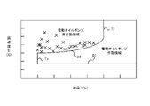
- FIG. 3 is a diagram showing an electric oil pump operating region and an electric oil pump non-operating region in a table consisting of oil temperature and deceleration.
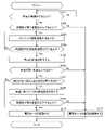
- FIG. 4 is a flowchart showing a process for determining whether the electric oil pump needs to be operated.
- Fig. 1 is a schematic configuration diagram of a vehicle.
- the vehicle includes an engine ENG as a first drive source, a torque converter TC, a forward/reverse switching mechanism SWM, and a variator VA.
- the transmission TM is a continuously variable belt transmission having a torque converter TC, a forward/reverse switching mechanism SWM, and a variator VA.
- the engine ENG constitutes the drive source of the vehicle.
- the power of the engine ENG is transmitted to the drive wheels DW via the torque converter TC, the forward/reverse switching mechanism SWM, and the variator VA.
- torque converter TC, forward/reverse switching mechanism SWM, and variator VA are provided in a power transmission path connecting engine ENG and drive wheels DW.
- the torque converter TC transmits power through fluid.
- the power transmission efficiency is enhanced by engaging the lockup clutch LU.
- the forward/reverse switching mechanism SWM is provided in the power transmission path connecting the engine ENG and the variator VA.
- the forward/reverse switching mechanism SWM switches the forward/rearward movement of the vehicle by switching the rotation direction of the input rotation.
- the forward/reverse switching mechanism SWM includes a forward clutch FWD/C that is engaged when the forward range is selected, and a reverse brake REV/B that is engaged when the reverse range is selected. When the forward clutch FWD/C and the reverse brake REV/B are released, the transmission TM is put into a neutral state, that is, a power cutoff state.
- the variator VA constitutes a belt continuously variable transmission mechanism having a primary pulley PRI, a secondary pulley SEC, and a belt BLT wound around the primary pulley PRI and the secondary pulley SEC.
- a primary pulley pressure Ppri which is the hydraulic pressure of the primary pulley PRI
- a secondary pulley pressure Psec which is the hydraulic pressure of the secondary pulley SEC
- the transmission TM further includes a mechanical oil pump MP as a first oil pump, an electric oil pump EP as a second oil pump, and an electric motor M as a second drive source.
- the mechanical oil pump MP pumps (supplies) oil to the hydraulic control circuit 1.
- a check valve 25 is provided in a flow path that communicates the mechanical oil pump MP and the hydraulic control circuit 1 .
- Mechanical oil pump MP is driven by the power of engine ENG.
- the electric oil pump EP pressure-feeds (supplies) oil to the hydraulic control circuit 1 together with the mechanical oil pump MP or independently.
- a check valve 26 is provided in a flow path that communicates the electric oil pump EP and the hydraulic control circuit 1 .
- the electric oil pump EP is provided auxiliary to the mechanical oil pump MP. That is, the electric oil pump EP temporarily supplies oil to the transmission TM based on the drive demand so as to compensate for the shortage of oil when the supply of oil from the mechanical oil pump MP to the transmission TM is stopped or runs short. supply.
- An electric motor M drives an electric oil pump EP. It may be understood that the electric oil pump EP is configured with an electric motor M.
- the transmission TM further includes a hydraulic control circuit 1 and a controller 2 as a vehicle control device.
- the hydraulic control circuit 1 includes a plurality of flow paths and a plurality of hydraulic control valves, regulates the pressure of oil supplied from the mechanical oil pump MP and the electric oil pump EP, and supplies the oil to each part of the transmission TM.
- the vehicle further includes various sensors 27.
- the various sensors 27 include an acceleration sensor 271 as acceleration detection means for detecting acceleration or deceleration of the vehicle, an engine rotation speed sensor 272 as engine rotation speed detection means for detecting the engine rotation speed, and an oil temperature sensor for detecting oil temperature. It has an oil temperature sensor 273 as temperature detection means.
- the controller 2 is a controller for controlling the transmission TM, and controls the hydraulic control circuit 1 and the electric motor M that drives the electric oil pump EP based on signals output from various sensors 27 and the like.
- the controller 2 is composed of a CPU as a computer, but is not limited to this, and may be composed of, for example, a plurality of microcomputers. Details of the controller 2 will be described later.
- the hydraulic control circuit 1 Based on commands from the controller 2, the hydraulic control circuit 1 performs hydraulic control of the lockup clutch LU, forward clutch FWD/C, reverse brake REV/B, primary pulley PRI, secondary pulley SEC, and the like.
- FIG. 2 is a configuration block diagram showing the main configuration connected to the controller 2 and the controller 2. As shown in FIG.
- the controller 2 includes an input interface 29, an output interface 30, a storage unit 31, a hydraulic control circuit control unit 32 (hereinafter simply referred to as circuit control unit 32), and an electric motor control unit, which are electrically connected to each other.
- a section 33 (hereinafter simply referred to as a motor control section 33) is provided.
- Output signals from various sensors 27 that detect various parameters are input to the input interface 29 .
- the circuit control command generated by the processing of the circuit control unit 32 and the motor control command generated by the processing of the motor control unit 33 are output to the hydraulic control circuit 1 and the electric motor M via the output interface 30, respectively.
- the storage unit 31 is a memory for temporarily storing various parameters included in output signals from the various sensors 27 .
- the storage unit 31 also stores processing programs and algorithm programs executed by the circuit control unit 32 and the motor control unit 33 .
- the storage unit 31 is built in the controller 2 in the present embodiment, the storage unit 31 is not limited to this, and may be provided separately from the controller 2, for example.
- the storage unit 31 stores a predetermined rotation speed, a first deceleration D1, a first oil temperature T1, a second oil temperature T2 as a predetermined oil temperature, and a predetermined deceleration, which are used in the operation necessity determination process of the electric oil pump EP.
- a predetermined function equation f(T) for obtaining the first deceleration D1, the first oil temperature T1, the second oil temperature T2, and the second deceleration D2 will be described later.
- the circuit control unit 32 generates circuit control commands based on output signals output from the various sensors 27 and outputs the generated circuit control commands to the hydraulic control circuit 1 via the output interface 30 .
- the motor control unit 33 generates a motor control command based on output signals output from the various sensors 27 and outputs the generated motor control command to the electric motor M via the output interface 30 .
- the motor control unit 33 also has a second deceleration determination module 331 as second deceleration determination means, a determination module 332 as determination means, and a command generation module 333 as command generation means.
- the details of the second deceleration determination module 331, the determination module 332, and the command generation module 333 will be described later in the operation necessity determination process for the electric oil pump EP.
- Fig. 3 is a diagram showing the operating region of the electric oil pump EP and the non-operating region of the electric oil pump EP in a table consisting of the oil temperature T and the deceleration D.
- the horizontal axis and the vertical axis represent the vehicle oil temperature T and the vehicle deceleration D, respectively.
- X in FIG. 3 indicates that air suction occurred in the experiment.
- the electric oil pump EP does not suck air, but air is supplied from the mechanical oil pump MP. It is possible to secure the necessary amount of oil with the oil that is used. Therefore, the region where the deceleration D of the vehicle is lower than the first deceleration D1 is defined as the non-operating region of the electric oil pump EP.
- the first deceleration D1 is a constant value that does not change with the oil temperature T of the vehicle. In this embodiment, the first deceleration D1 is a fixed value, but may be changed.
- the region where the oil temperature T of the vehicle is lower than the first oil temperature T1 is defined as the non-operating region of the electric oil pump EP.
- the first oil temperature T1 is a constant value that does not change with the deceleration D. In this embodiment, the first oil temperature T1 is a fixed value, but may be changed.
- the region where the deceleration of the vehicle is equal to or higher than the first deceleration D1 and the oil temperature T of the vehicle is equal to or higher than the second oil temperature T2 is defined as the operation region of the electric oil pump EP.
- the second oil temperature T2 is a constant value that does not change with the deceleration D. In this embodiment, the second oil temperature T2 is a fixed value, but may be changed.
- a second deceleration D2 is set as a predetermined deceleration in which the oil temperature T of the vehicle is between the first oil temperature T1 and the second oil temperature T2 and the deceleration D of the vehicle is greater than the first deceleration D1. If it exceeds, the electric oil pump EP will suck air. Therefore, the non-operating region of the electric oil pump EP is defined as the region where the oil temperature T of the vehicle is between the first oil temperature T1 and the second oil temperature T2 and the deceleration of the vehicle exceeds the second deceleration D2.
- the second deceleration D2 is a variable value that changes depending on the oil temperature T of the vehicle. As a result, compared to the case where the second deceleration D2 is a constant value that does not change with the oil temperature T of the vehicle, the operating range of the electric oil pump EP can be increased.
- the higher the oil temperature T of the vehicle the more difficult it is for the electric oil pump EP to suck air even if the deceleration D of the vehicle increases. It is determined so that the higher the oil temperature T is, the larger it becomes.
- the oil temperature T of the vehicle is high, it becomes easier to drive the electric oil pump EP, and even if the vehicle speed decreases, the amount of oil can be suppressed from decreasing, so that the vehicle can smoothly shift gears. It can be carried out. As a result, it is possible to obtain the reduction gear ratio necessary for starting the vehicle when the vehicle is stopped, so that the acceleration when starting the vehicle can be obtained.
- the second deceleration D2 is obtained (determined) based on the oil temperature T of the vehicle and a preset function equation f(T).
- the second deceleration D2 fluctuates so as to increase as the oil temperature T of the vehicle increases.
- the oil temperature T of the vehicle is between the first oil temperature T1 and the second oil temperature T2
- the deceleration D of the vehicle is between the first deceleration D1 and the second deceleration D2.
- the electric oil pump EP does not suck in air. Therefore, the oil temperature T of the vehicle is between the first oil temperature T1 and the second oil temperature T2, and the deceleration D of the vehicle is between the first deceleration D1 and the second deceleration D2.
- the area is assumed to be the operation area of the electric oil pump EP.
- FIG. 4 is a flow chart showing the operation necessity determination process for the electric oil pump EP.
- step S101 the determination module 332 of the motor control unit 33 determines whether or not the vehicle is decelerating based on the signal output from the acceleration sensor 271. If the vehicle is decelerating (Yes), the process proceeds to step S102. On the other hand, if the vehicle is not decelerating (No), step S101 is repeated.
- step S102 the determination module 332 determines whether the deceleration D of the vehicle detected by the acceleration sensor 271 is greater than or equal to the first deceleration D1. If the deceleration D of the vehicle is greater than or equal to the first deceleration D1 (Yes), the process proceeds to step S103. On the other hand, if the deceleration D of the vehicle is less than the first deceleration D1 (No), the process proceeds to step S111.
- step S103 the engine rotation speed sensor 272 detects the rotation speed of the engine ENG, outputs the detected rotation speed of the engine ENG to the motor control section 33 via the input interface 29, and proceeds to step S104.
- step S104 the determination module 332 determines whether or not the rotation speed of the engine ENG detected by the engine rotation speed sensor 272 is equal to or lower than a predetermined rotation speed. If the rotation speed of the engine ENG is equal to or lower than the predetermined rotation speed (Yes), the process proceeds to step S105. On the other hand, if the rotation speed of the engine ENG exceeds the predetermined rotation speed (No), the process returns to step S103.
- step S105 the oil temperature sensor 273 detects the oil temperature T of the vehicle, outputs the detected oil temperature T of the vehicle to the motor control unit 33 via the input interface 29, and proceeds to step S106.
- step S106 the determination module 332 determines whether or not the vehicle oil temperature T detected by the oil temperature sensor 273 is equal to or higher than the first oil temperature T1. If the oil temperature T of the vehicle is equal to or higher than the first oil temperature T1 (Yes), the process proceeds to step S107. On the other hand, when the vehicle oil temperature T is lower than the first oil temperature T1 (No), the process proceeds to step S111.
- step S107 the determination module 332 determines whether or not the vehicle oil temperature T detected by the oil temperature sensor 273 is between the first oil temperature T1 and the second oil temperature T2. If the vehicle oil temperature T is between the first oil temperature T1 and the second oil temperature T2 (Yes), the process proceeds to step S108. On the other hand, if the oil temperature T of the vehicle exceeds the second oil temperature T2 (No), the process proceeds to step S110.
- step S108 the second deceleration determination module 331 obtains the second deceleration D2 based on the oil temperature T of the vehicle detected by the oil temperature sensor 273, and proceeds to step S109. Specifically, in step S108, the second deceleration determination module 331 determines the second deceleration D2 based on the oil temperature T of the vehicle and the predetermined function equation f(T) stored in advance in the storage unit 31. demand. The second deceleration determination module 331 then outputs the determined second deceleration D2 to the determination module 332 .
- step S109 the determination module 332 of the motor control unit 33 determines whether or not the deceleration D of the vehicle is equal to or less than the second deceleration D2. If the deceleration D of the vehicle is equal to or less than the second deceleration D2 (Yes), the process proceeds to step S110. On the other hand, if the deceleration D of the vehicle exceeds the second deceleration D2 (No), the process proceeds to step S111.
- step S110 the motor control unit 33 drives the electric motor M so as to supply hydraulic pressure from the electric oil pump EP to the transmission TM.
- the command generation module 333 of the motor control unit 33 generates an oil supply command based on the No determination in step S107 or the Yes determination in step S109.
- the command generation module 333 then outputs the generated oil supply command to the electric motor M via the output interface 30 .
- the electric motor M is driven based on the oil supply command output from the command generation module 333, and operates the electric oil pump EP to supply hydraulic pressure from the electric oil pump EP to the transmission TM. Then, this process is terminated.
- step S107 that is, if the deceleration D of the vehicle is equal to or greater than the first deceleration D1 and the oil temperature T of the vehicle exceeds the second oil temperature T2, the motor control unit 33 controls the electric oil Even if the electric motor M is driven so as to supply hydraulic pressure from the pump EP to the transmission TM, the electric oil pump EP does not suck air. Therefore, there is no effect on the transmission TM due to air suction by the electric oil pump EP. Therefore, even if the deceleration D of the vehicle is large, the driving of the electric oil pump EP is not restricted. It is possible to smoothly shift the speed of the vehicle. As a result, it is possible to obtain the reduction gear ratio necessary for starting the vehicle when the vehicle is stopped, so that the acceleration when starting the vehicle can be obtained.
- step S109 that is, the vehicle oil temperature T is between the first oil temperature T1 and the second oil temperature T2, and the vehicle deceleration D is the first deceleration D1 and the second deceleration D2, even if the motor control unit 33 drives the electric motor M so as to supply hydraulic pressure from the electric oil pump EP to the transmission TM, the electric oil pump EP does not suck air. Therefore, there is no effect on the transmission TM due to air suction by the electric oil pump EP.
- step S111 the motor control unit 33 limits the driving of the electric motor M so that hydraulic pressure is not supplied from the electric oil pump EP to the transmission TM.
- the command generation module 333 generates an oil non-supply command based on the No determination in step S104, the No determination in step S106, or the No determination in step S109.
- the command generation module 333 then outputs the generated oil non-supply command to the electric motor M via the output interface 30 .
- the driving of the electric motor M is restricted based on the oil non-supply command output from the command generation module 333, and by not operating the electric oil pump EP, hydraulic pressure is not supplied from the electric oil pump EP to the transmission TM. .
- the engine ENG is controlled to increase its rotational speed. Then, this process is terminated.
- step S104 that is, if the deceleration D of the vehicle is less than the first deceleration D1, the drive of the electric motor M is restricted so as not to supply hydraulic pressure from the electric oil pump EP to the transmission TM. It is possible to prevent deterioration in the durability of the electric oil pump EP due to excessive frequency of use of the electric oil pump EP.
- step S106 that is, if the oil temperature T of the vehicle is lower than the first oil temperature T1, the driving of the electric motor M is restricted so that the oil pressure is not supplied from the electric oil pump EP to the transmission TM. Therefore, it is possible to prevent the durability of the electric oil pump EP from deteriorating due to excessive frequency of use of the electric oil pump EP.
- step S109 that is, if the vehicle oil temperature T is between the first oil temperature T1 and the second oil temperature T2 and the vehicle deceleration D exceeds the second deceleration D2,
- the electric motor M is driven to operate the electric oil pump EP, the electric oil pump EP sucks air. Therefore, the driving of the electric motor M is restricted so as not to supply hydraulic pressure from the electric oil pump EP to the transmission TM. As a result, the influence of the air suction of the electric oil pump EP on the transmission TM can be reduced. Further, in response to subsequent acceleration requests, a higher driving force can be transmitted than when the electric oil pump EP is actuated, so that the sense of discomfort given to the driver can be reduced.
- the vehicle controller 2 (control device) includes a mechanical oil pump MP (first oil pump) driven by an engine ENG (first drive source) that drives the drive wheels DW, and an electric motor.
- An electric oil pump EP (second oil pump) driven by an M (second drive source) and a transmission TM having an engine ENG (first drive source).
- the rotation speed of the motor M (second drive source) is supplied to the transmission TM from the electric oil pump EP (second oil pump) when the rotation speed of the motor M drops below a predetermined rotation speed due to deceleration of the vehicle. is controlled, and the electric motor M ( second drive source).
- a vehicle control method includes a mechanical oil pump MP (first oil pump) driven by an engine ENG (first drive source) that drives drive wheels DW, an electric motor M (second A control method for a vehicle having a transmission TM having an electric oil pump EP (second oil pump) driven by a drive source), wherein the rotation speed of the engine ENG (first drive source) is reduced by deceleration of the vehicle.
- the electric motor M (second drive source) is controlled so as not to supply hydraulic pressure from the electric oil pump EP (second oil pump) to the transmission TM. and limiting the drive.
- the program according to the present embodiment includes a mechanical oil pump MP (first oil pump) driven by an engine ENG (first drive source) that drives the drive wheels DW, and an electric motor M (second drive source).
- a computer-executable program for controlling a vehicle comprising a transmission TM having an electric oil pump EP (second oil pump) driven by a procedure for controlling the drive of the electric motor M (second drive source) so that hydraulic pressure is supplied from the electric oil pump EP (second oil pump) to the transmission TM when the rotation speed drops below a predetermined rotational speed due to the deceleration of , when the deceleration D of the vehicle exceeds the second deceleration D2 (predetermined deceleration), the electric motor M (second driving causes the computer to perform a procedure for restricting the driving of the power source);
- the electric motor M if the electric motor M is driven to operate the electric oil pump EP when the deceleration D of the vehicle exceeds the second deceleration D2, the electric oil pump EP sucks air.
- the driving of the electric motor M is restricted so as not to supply oil pressure from the electric oil pump EP to the transmission TM.
- the influence of the air suction of the electric oil pump EP on the transmission TM can be reduced.
- a higher driving force can be transmitted than when the electric oil pump EP is actuated, so that the sense of discomfort given to the driver can be reduced.
- the second deceleration D2 (predetermined deceleration) changes according to the oil temperature T.
- the controller 2 supplies hydraulic pressure from the electric oil pump EP (second oil pump) to the transmission TM when the oil temperature T is equal to or higher than a second oil temperature T2 (predetermined oil temperature).
- the drive of the electric motor M (second drive source) is controlled as follows.
- the motor control unit 33 drives the electric motor M so as to supply hydraulic pressure from the electric oil pump EP to the transmission TM. Also, since the electric oil pump EP does not suck air, there is no effect on the transmission TM due to the air sucked by the electric oil pump EP. Therefore, even if the deceleration D of the vehicle is large, the driving of the electric oil pump EP is not restricted, so even if the vehicle speed drops while the deceleration D of the vehicle is large, the oil amount can be prevented from decreasing. , the vehicle can be smoothly shifted. As a result, it is possible to obtain the reduction gear ratio necessary for starting the vehicle when the vehicle is stopped, so that the acceleration when starting the vehicle can be obtained.
- the first oil pump and the second oil pump are composed of the mechanical oil pump MP and the electric oil pump EP, respectively. It may be composed of an EP.
Landscapes
- Engineering & Computer Science (AREA)
- General Engineering & Computer Science (AREA)
- Mechanical Engineering (AREA)
- Oil, Petroleum & Natural Gas (AREA)
- Control Of Transmission Device (AREA)
Priority Applications (4)
| Application Number | Priority Date | Filing Date | Title |
|---|---|---|---|
| JP2023531817A JPWO2023276752A1 (https=) | 2021-07-02 | 2022-06-20 | |
| CN202280046364.6A CN117581047A (zh) | 2021-07-02 | 2022-06-20 | 车辆的控制装置、车辆的控制方法及程序 |
| US18/575,174 US12222032B2 (en) | 2021-07-02 | 2022-06-20 | Control device for vehicle, control method for vehicle, and non-transitory computer-readable medium |
| JP2025176297A JP2026004620A (ja) | 2021-07-02 | 2025-10-20 | 車両の制御装置、車両の制御方法及びプログラム |
Applications Claiming Priority (2)
| Application Number | Priority Date | Filing Date | Title |
|---|---|---|---|
| JP2021-110773 | 2021-07-02 | ||
| JP2021110773 | 2021-07-02 |
Publications (1)
| Publication Number | Publication Date |
|---|---|
| WO2023276752A1 true WO2023276752A1 (ja) | 2023-01-05 |
Family
ID=84691744
Family Applications (1)
| Application Number | Title | Priority Date | Filing Date |
|---|---|---|---|
| PCT/JP2022/024502 Ceased WO2023276752A1 (ja) | 2021-07-02 | 2022-06-20 | 車両の制御装置、車両の制御方法及びプログラム |
Country Status (4)
| Country | Link |
|---|---|
| US (1) | US12222032B2 (https=) |
| JP (2) | JPWO2023276752A1 (https=) |
| CN (1) | CN117581047A (https=) |
| WO (1) | WO2023276752A1 (https=) |
Cited By (1)
| Publication number | Priority date | Publication date | Assignee | Title |
|---|---|---|---|---|
| JP2025012139A (ja) * | 2023-07-12 | 2025-01-24 | トヨタ自動車株式会社 | 電動車両の冷却制御装置 |
Citations (4)
| Publication number | Priority date | Publication date | Assignee | Title |
|---|---|---|---|---|
| JP2010149630A (ja) * | 2008-12-24 | 2010-07-08 | Nissan Motor Co Ltd | 車両の急減速制御装置及び急減速制御方法 |
| WO2011062204A1 (ja) * | 2009-11-18 | 2011-05-26 | 本田技研工業株式会社 | 車両の制御装置 |
| JP2014034983A (ja) * | 2012-08-07 | 2014-02-24 | Fuji Heavy Ind Ltd | 作動油供給装置 |
| JP2020196362A (ja) * | 2019-06-04 | 2020-12-10 | ジヤトコ株式会社 | 車両用制御装置 |
Family Cites Families (10)
| Publication number | Priority date | Publication date | Assignee | Title |
|---|---|---|---|---|
| JP3468810B2 (ja) | 1993-12-21 | 2003-11-17 | ジヤトコ株式会社 | 自動変速機の油圧制御装置 |
| JP4229867B2 (ja) * | 2004-03-31 | 2009-02-25 | 本田技研工業株式会社 | 圧縮比可変機構を備える内燃機関を備える動力装置 |
| JP2010007834A (ja) | 2008-06-30 | 2010-01-14 | Toyota Motor Corp | 無段変速機の制御装置および制御方法 |
| JP5191971B2 (ja) * | 2009-10-06 | 2013-05-08 | ジヤトコ株式会社 | 車両のオイルポンプ制御装置 |
| JP5237981B2 (ja) | 2010-03-09 | 2013-07-17 | ジヤトコ株式会社 | 自動変速機およびその制御方法 |
| JP2012154392A (ja) | 2011-01-25 | 2012-08-16 | Mazda Motor Corp | 自動変速機の制御装置 |
| EP2752572B1 (en) * | 2011-08-31 | 2017-12-13 | JATCO Ltd | Coast stop vehicle |
| JP2017044069A (ja) | 2015-08-24 | 2017-03-02 | 富士重工業株式会社 | 車両用制御装置 |
| JP2018054066A (ja) * | 2016-09-30 | 2018-04-05 | 株式会社Subaru | 無段変速機 |
| JP6809293B2 (ja) | 2017-03-01 | 2021-01-06 | トヨタ自動車株式会社 | 車両の制御装置 |
-
2022
- 2022-06-20 CN CN202280046364.6A patent/CN117581047A/zh active Pending
- 2022-06-20 JP JP2023531817A patent/JPWO2023276752A1/ja active Pending
- 2022-06-20 WO PCT/JP2022/024502 patent/WO2023276752A1/ja not_active Ceased
- 2022-06-20 US US18/575,174 patent/US12222032B2/en active Active
-
2025
- 2025-10-20 JP JP2025176297A patent/JP2026004620A/ja active Pending
Patent Citations (4)
| Publication number | Priority date | Publication date | Assignee | Title |
|---|---|---|---|---|
| JP2010149630A (ja) * | 2008-12-24 | 2010-07-08 | Nissan Motor Co Ltd | 車両の急減速制御装置及び急減速制御方法 |
| WO2011062204A1 (ja) * | 2009-11-18 | 2011-05-26 | 本田技研工業株式会社 | 車両の制御装置 |
| JP2014034983A (ja) * | 2012-08-07 | 2014-02-24 | Fuji Heavy Ind Ltd | 作動油供給装置 |
| JP2020196362A (ja) * | 2019-06-04 | 2020-12-10 | ジヤトコ株式会社 | 車両用制御装置 |
Cited By (1)
| Publication number | Priority date | Publication date | Assignee | Title |
|---|---|---|---|---|
| JP2025012139A (ja) * | 2023-07-12 | 2025-01-24 | トヨタ自動車株式会社 | 電動車両の冷却制御装置 |
Also Published As
| Publication number | Publication date |
|---|---|
| JPWO2023276752A1 (https=) | 2023-01-05 |
| US20240426376A1 (en) | 2024-12-26 |
| US12222032B2 (en) | 2025-02-11 |
| JP2026004620A (ja) | 2026-01-14 |
| CN117581047A (zh) | 2024-02-20 |
Similar Documents
| Publication | Publication Date | Title |
|---|---|---|
| RU2509939C1 (ru) | Автоматическая трансмиссия и способ ее управления | |
| KR101362103B1 (ko) | 무단 변속기의 제어 장치 | |
| CN104246318B (zh) | 车辆的起步控制装置及起步控制方法 | |
| US8992380B2 (en) | Vehicle control device | |
| WO2016006421A1 (ja) | ロックアップクラッチの制御装置 | |
| KR101586162B1 (ko) | 무단 변속기 및 그 유압 제어 방법 | |
| KR20140137382A (ko) | 무단 변속기 및 그 유압 제어 방법 | |
| JP2026004620A (ja) | 車両の制御装置、車両の制御方法及びプログラム | |
| US10711884B2 (en) | Control method and control device of continuously variable transmission | |
| CN103597252A (zh) | 滑行停止车辆 | |
| CN109642659B (zh) | 无级变速器以及无级变速器的控制方法 | |
| EP2792911B1 (en) | Continuously-variable transmission and continuously-variable transmission control method | |
| US12173789B2 (en) | Hydraulic control device for hydraulic actuation machine, hydraulic control method for hydraulic actuation machine, and non-transitory computer-readable medium | |
| JP2019211025A (ja) | 車両の制御装置及び車両の制御方法 | |
| JP6772846B2 (ja) | 無段変速機の制御方法 | |
| KR20160040334A (ko) | 무단 변속기의 슬립 제어 방법 | |
| US12523293B2 (en) | Control device for transmission, control method for transmission, and non-transitory computer-readable medium | |
| US12215784B2 (en) | Transmission, method for controlling transmission, and non-transitory computer- readable medium | |
| JP7641163B2 (ja) | 自動変速機の制御装置、自動変速機の制御方法、車両、及び車両の制御方法 | |
| JP2009216172A (ja) | 無段変速機制御装置 | |
| WO2025215909A1 (ja) | 車両の制御装置、車両の制御方法、及びプログラム | |
| KR101664881B1 (ko) | 무단 변속기의 변속비 제어 방법 | |
| JP2018168860A (ja) | 変速制御装置 | |
| WO2022149363A1 (ja) | 変速機の油圧制御回路、変速機の油圧制御方法、及びプログラム | |
| CN111542711A (zh) | 动力传递装置的控制方法以及动力传递装置的控制装置 |
Legal Events
| Date | Code | Title | Description |
|---|---|---|---|
| 121 | Ep: the epo has been informed by wipo that ep was designated in this application |
Ref document number: 22832902 Country of ref document: EP Kind code of ref document: A1 |
|
| DPE1 | Request for preliminary examination filed after expiration of 19th month from priority date (pct application filed from 20040101) | ||
| WWE | Wipo information: entry into national phase |
Ref document number: 2023531817 Country of ref document: JP |
|
| WWE | Wipo information: entry into national phase |
Ref document number: 18575174 Country of ref document: US Ref document number: 202280046364.6 Country of ref document: CN |
|
| NENP | Non-entry into the national phase |
Ref country code: DE |
|
| 122 | Ep: pct application non-entry in european phase |
Ref document number: 22832902 Country of ref document: EP Kind code of ref document: A1 |