WO2023276752A1 - Vehicle control device, vehicle control method, and program - Google Patents
Vehicle control device, vehicle control method, and program Download PDFInfo
- Publication number
- WO2023276752A1 WO2023276752A1 PCT/JP2022/024502 JP2022024502W WO2023276752A1 WO 2023276752 A1 WO2023276752 A1 WO 2023276752A1 JP 2022024502 W JP2022024502 W JP 2022024502W WO 2023276752 A1 WO2023276752 A1 WO 2023276752A1
- Authority
- WO
- WIPO (PCT)
- Prior art keywords
- oil pump
- vehicle
- deceleration
- transmission
- drive source
- Prior art date
Links
- 238000000034 method Methods 0.000 title claims abstract description 33
- 230000005540 biological transmission Effects 0.000 claims abstract description 66
- 230000000694 effects Effects 0.000 abstract description 6
- 230000008569 process Effects 0.000 description 18
- 230000001133 acceleration Effects 0.000 description 12
- 230000002441 reversible effect Effects 0.000 description 11
- 230000007246 mechanism Effects 0.000 description 8
- 238000010586 diagram Methods 0.000 description 6
- 230000008859 change Effects 0.000 description 5
- 230000006870 function Effects 0.000 description 4
- 230000009467 reduction Effects 0.000 description 4
- 238000001514 detection method Methods 0.000 description 3
- 230000003247 decreasing effect Effects 0.000 description 2
- 230000004044 response Effects 0.000 description 2
- 230000007423 decrease Effects 0.000 description 1
- 230000003111 delayed effect Effects 0.000 description 1
- 230000006866 deterioration Effects 0.000 description 1
- 230000002542 deteriorative effect Effects 0.000 description 1
- 238000002474 experimental method Methods 0.000 description 1
- 239000012530 fluid Substances 0.000 description 1
- 230000004048 modification Effects 0.000 description 1
- 238000012986 modification Methods 0.000 description 1
- 230000007935 neutral effect Effects 0.000 description 1
Images


Classifications
-
- F—MECHANICAL ENGINEERING; LIGHTING; HEATING; WEAPONS; BLASTING
- F16—ENGINEERING ELEMENTS AND UNITS; GENERAL MEASURES FOR PRODUCING AND MAINTAINING EFFECTIVE FUNCTIONING OF MACHINES OR INSTALLATIONS; THERMAL INSULATION IN GENERAL
- F16H—GEARING
- F16H59/00—Control inputs to control units of change-speed-, or reversing-gearings for conveying rotary motion
- F16H59/36—Inputs being a function of speed
- F16H59/38—Inputs being a function of speed of gearing elements
- F16H59/42—Input shaft speed
-
- F—MECHANICAL ENGINEERING; LIGHTING; HEATING; WEAPONS; BLASTING
- F16—ENGINEERING ELEMENTS AND UNITS; GENERAL MEASURES FOR PRODUCING AND MAINTAINING EFFECTIVE FUNCTIONING OF MACHINES OR INSTALLATIONS; THERMAL INSULATION IN GENERAL
- F16H—GEARING
- F16H59/00—Control inputs to control units of change-speed-, or reversing-gearings for conveying rotary motion
- F16H59/48—Inputs being a function of acceleration
-
- F—MECHANICAL ENGINEERING; LIGHTING; HEATING; WEAPONS; BLASTING
- F16—ENGINEERING ELEMENTS AND UNITS; GENERAL MEASURES FOR PRODUCING AND MAINTAINING EFFECTIVE FUNCTIONING OF MACHINES OR INSTALLATIONS; THERMAL INSULATION IN GENERAL
- F16H—GEARING
- F16H59/00—Control inputs to control units of change-speed-, or reversing-gearings for conveying rotary motion
- F16H59/68—Inputs being a function of gearing status
- F16H59/72—Inputs being a function of gearing status dependent on oil characteristics, e.g. temperature, viscosity
-
- F—MECHANICAL ENGINEERING; LIGHTING; HEATING; WEAPONS; BLASTING
- F16—ENGINEERING ELEMENTS AND UNITS; GENERAL MEASURES FOR PRODUCING AND MAINTAINING EFFECTIVE FUNCTIONING OF MACHINES OR INSTALLATIONS; THERMAL INSULATION IN GENERAL
- F16H—GEARING
- F16H61/00—Control functions within control units of change-speed- or reversing-gearings for conveying rotary motion ; Control of exclusively fluid gearing, friction gearing, gearings with endless flexible members or other particular types of gearing
- F16H61/02—Control functions within control units of change-speed- or reversing-gearings for conveying rotary motion ; Control of exclusively fluid gearing, friction gearing, gearings with endless flexible members or other particular types of gearing characterised by the signals used
-
- F—MECHANICAL ENGINEERING; LIGHTING; HEATING; WEAPONS; BLASTING
- F16—ENGINEERING ELEMENTS AND UNITS; GENERAL MEASURES FOR PRODUCING AND MAINTAINING EFFECTIVE FUNCTIONING OF MACHINES OR INSTALLATIONS; THERMAL INSULATION IN GENERAL
- F16H—GEARING
- F16H63/00—Control outputs from the control unit to change-speed- or reversing-gearings for conveying rotary motion or to other devices than the final output mechanism
- F16H63/40—Control outputs from the control unit to change-speed- or reversing-gearings for conveying rotary motion or to other devices than the final output mechanism comprising signals other than signals for actuating the final output mechanisms
Definitions
- the present invention relates to a vehicle control device, a vehicle control method, and a program.
- a pump drive control means starts driving an electric oil pump at a vehicle speed detected by a vehicle speed detecting means as the deceleration request detected by the deceleration request detecting means increases. Controlling the drive of an electric oil pump is disclosed.
- a vehicle including a transmission having a first oil pump driven by a first drive source that drives drive wheels and a second oil pump driven by a second drive source
- the second drive is configured to supply hydraulic pressure from the second oil pump to the transmission. control the drive of the second drive source, and limit the drive of the second drive source so that hydraulic pressure is not supplied from the second oil pump to the transmission when the deceleration of the vehicle exceeds a predetermined deceleration;
- a vehicle including a transmission having a first oil pump driven by a first drive source that drives drive wheels and a second oil pump driven by a second drive source
- the second oil pump supplies hydraulic pressure to the transmission.
- a vehicle including a transmission having a first oil pump driven by a first drive source that drives drive wheels and a second oil pump driven by a second drive source
- a computer-executable program that controls the second oil pump to supply hydraulic pressure to the transmission when the rotation speed of the first drive source falls below a predetermined rotation speed due to deceleration of the vehicle and a procedure for controlling the drive of the second drive source so that the second drive source does not supply hydraulic pressure from the second oil pump to the transmission when deceleration of the vehicle exceeds a predetermined deceleration.
- a program is provided which causes the computer to perform a procedure for limiting the drive of the source.
- FIG. 1 is a schematic configuration diagram of a vehicle.
- FIG. 2 is a configuration block diagram showing the main configuration connected to the controller and the controller.
- FIG. 3 is a diagram showing an electric oil pump operating region and an electric oil pump non-operating region in a table consisting of oil temperature and deceleration.
- FIG. 4 is a flowchart showing a process for determining whether the electric oil pump needs to be operated.
- Fig. 1 is a schematic configuration diagram of a vehicle.
- the vehicle includes an engine ENG as a first drive source, a torque converter TC, a forward/reverse switching mechanism SWM, and a variator VA.
- the transmission TM is a continuously variable belt transmission having a torque converter TC, a forward/reverse switching mechanism SWM, and a variator VA.
- the engine ENG constitutes the drive source of the vehicle.
- the power of the engine ENG is transmitted to the drive wheels DW via the torque converter TC, the forward/reverse switching mechanism SWM, and the variator VA.
- torque converter TC, forward/reverse switching mechanism SWM, and variator VA are provided in a power transmission path connecting engine ENG and drive wheels DW.
- the torque converter TC transmits power through fluid.
- the power transmission efficiency is enhanced by engaging the lockup clutch LU.
- the forward/reverse switching mechanism SWM is provided in the power transmission path connecting the engine ENG and the variator VA.
- the forward/reverse switching mechanism SWM switches the forward/rearward movement of the vehicle by switching the rotation direction of the input rotation.
- the forward/reverse switching mechanism SWM includes a forward clutch FWD/C that is engaged when the forward range is selected, and a reverse brake REV/B that is engaged when the reverse range is selected. When the forward clutch FWD/C and the reverse brake REV/B are released, the transmission TM is put into a neutral state, that is, a power cutoff state.
- the variator VA constitutes a belt continuously variable transmission mechanism having a primary pulley PRI, a secondary pulley SEC, and a belt BLT wound around the primary pulley PRI and the secondary pulley SEC.
- a primary pulley pressure Ppri which is the hydraulic pressure of the primary pulley PRI
- a secondary pulley pressure Psec which is the hydraulic pressure of the secondary pulley SEC
- the transmission TM further includes a mechanical oil pump MP as a first oil pump, an electric oil pump EP as a second oil pump, and an electric motor M as a second drive source.
- the mechanical oil pump MP pumps (supplies) oil to the hydraulic control circuit 1.
- a check valve 25 is provided in a flow path that communicates the mechanical oil pump MP and the hydraulic control circuit 1 .
- Mechanical oil pump MP is driven by the power of engine ENG.
- the electric oil pump EP pressure-feeds (supplies) oil to the hydraulic control circuit 1 together with the mechanical oil pump MP or independently.
- a check valve 26 is provided in a flow path that communicates the electric oil pump EP and the hydraulic control circuit 1 .
- the electric oil pump EP is provided auxiliary to the mechanical oil pump MP. That is, the electric oil pump EP temporarily supplies oil to the transmission TM based on the drive demand so as to compensate for the shortage of oil when the supply of oil from the mechanical oil pump MP to the transmission TM is stopped or runs short. supply.
- An electric motor M drives an electric oil pump EP. It may be understood that the electric oil pump EP is configured with an electric motor M.
- the transmission TM further includes a hydraulic control circuit 1 and a controller 2 as a vehicle control device.
- the hydraulic control circuit 1 includes a plurality of flow paths and a plurality of hydraulic control valves, regulates the pressure of oil supplied from the mechanical oil pump MP and the electric oil pump EP, and supplies the oil to each part of the transmission TM.
- the vehicle further includes various sensors 27.
- the various sensors 27 include an acceleration sensor 271 as acceleration detection means for detecting acceleration or deceleration of the vehicle, an engine rotation speed sensor 272 as engine rotation speed detection means for detecting the engine rotation speed, and an oil temperature sensor for detecting oil temperature. It has an oil temperature sensor 273 as temperature detection means.
- the controller 2 is a controller for controlling the transmission TM, and controls the hydraulic control circuit 1 and the electric motor M that drives the electric oil pump EP based on signals output from various sensors 27 and the like.
- the controller 2 is composed of a CPU as a computer, but is not limited to this, and may be composed of, for example, a plurality of microcomputers. Details of the controller 2 will be described later.
- the hydraulic control circuit 1 Based on commands from the controller 2, the hydraulic control circuit 1 performs hydraulic control of the lockup clutch LU, forward clutch FWD/C, reverse brake REV/B, primary pulley PRI, secondary pulley SEC, and the like.
- FIG. 2 is a configuration block diagram showing the main configuration connected to the controller 2 and the controller 2. As shown in FIG.
- the controller 2 includes an input interface 29, an output interface 30, a storage unit 31, a hydraulic control circuit control unit 32 (hereinafter simply referred to as circuit control unit 32), and an electric motor control unit, which are electrically connected to each other.
- a section 33 (hereinafter simply referred to as a motor control section 33) is provided.
- Output signals from various sensors 27 that detect various parameters are input to the input interface 29 .
- the circuit control command generated by the processing of the circuit control unit 32 and the motor control command generated by the processing of the motor control unit 33 are output to the hydraulic control circuit 1 and the electric motor M via the output interface 30, respectively.
- the storage unit 31 is a memory for temporarily storing various parameters included in output signals from the various sensors 27 .
- the storage unit 31 also stores processing programs and algorithm programs executed by the circuit control unit 32 and the motor control unit 33 .
- the storage unit 31 is built in the controller 2 in the present embodiment, the storage unit 31 is not limited to this, and may be provided separately from the controller 2, for example.
- the storage unit 31 stores a predetermined rotation speed, a first deceleration D1, a first oil temperature T1, a second oil temperature T2 as a predetermined oil temperature, and a predetermined deceleration, which are used in the operation necessity determination process of the electric oil pump EP.
- a predetermined function equation f(T) for obtaining the first deceleration D1, the first oil temperature T1, the second oil temperature T2, and the second deceleration D2 will be described later.
- the circuit control unit 32 generates circuit control commands based on output signals output from the various sensors 27 and outputs the generated circuit control commands to the hydraulic control circuit 1 via the output interface 30 .
- the motor control unit 33 generates a motor control command based on output signals output from the various sensors 27 and outputs the generated motor control command to the electric motor M via the output interface 30 .
- the motor control unit 33 also has a second deceleration determination module 331 as second deceleration determination means, a determination module 332 as determination means, and a command generation module 333 as command generation means.
- the details of the second deceleration determination module 331, the determination module 332, and the command generation module 333 will be described later in the operation necessity determination process for the electric oil pump EP.
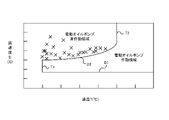
- Fig. 3 is a diagram showing the operating region of the electric oil pump EP and the non-operating region of the electric oil pump EP in a table consisting of the oil temperature T and the deceleration D.
- the horizontal axis and the vertical axis represent the vehicle oil temperature T and the vehicle deceleration D, respectively.
- X in FIG. 3 indicates that air suction occurred in the experiment.
- the electric oil pump EP does not suck air, but air is supplied from the mechanical oil pump MP. It is possible to secure the necessary amount of oil with the oil that is used. Therefore, the region where the deceleration D of the vehicle is lower than the first deceleration D1 is defined as the non-operating region of the electric oil pump EP.
- the first deceleration D1 is a constant value that does not change with the oil temperature T of the vehicle. In this embodiment, the first deceleration D1 is a fixed value, but may be changed.
- the region where the oil temperature T of the vehicle is lower than the first oil temperature T1 is defined as the non-operating region of the electric oil pump EP.
- the first oil temperature T1 is a constant value that does not change with the deceleration D. In this embodiment, the first oil temperature T1 is a fixed value, but may be changed.
- the region where the deceleration of the vehicle is equal to or higher than the first deceleration D1 and the oil temperature T of the vehicle is equal to or higher than the second oil temperature T2 is defined as the operation region of the electric oil pump EP.
- the second oil temperature T2 is a constant value that does not change with the deceleration D. In this embodiment, the second oil temperature T2 is a fixed value, but may be changed.
- a second deceleration D2 is set as a predetermined deceleration in which the oil temperature T of the vehicle is between the first oil temperature T1 and the second oil temperature T2 and the deceleration D of the vehicle is greater than the first deceleration D1. If it exceeds, the electric oil pump EP will suck air. Therefore, the non-operating region of the electric oil pump EP is defined as the region where the oil temperature T of the vehicle is between the first oil temperature T1 and the second oil temperature T2 and the deceleration of the vehicle exceeds the second deceleration D2.
- the second deceleration D2 is a variable value that changes depending on the oil temperature T of the vehicle. As a result, compared to the case where the second deceleration D2 is a constant value that does not change with the oil temperature T of the vehicle, the operating range of the electric oil pump EP can be increased.
- the higher the oil temperature T of the vehicle the more difficult it is for the electric oil pump EP to suck air even if the deceleration D of the vehicle increases. It is determined so that the higher the oil temperature T is, the larger it becomes.
- the oil temperature T of the vehicle is high, it becomes easier to drive the electric oil pump EP, and even if the vehicle speed decreases, the amount of oil can be suppressed from decreasing, so that the vehicle can smoothly shift gears. It can be carried out. As a result, it is possible to obtain the reduction gear ratio necessary for starting the vehicle when the vehicle is stopped, so that the acceleration when starting the vehicle can be obtained.
- the second deceleration D2 is obtained (determined) based on the oil temperature T of the vehicle and a preset function equation f(T).
- the second deceleration D2 fluctuates so as to increase as the oil temperature T of the vehicle increases.
- the oil temperature T of the vehicle is between the first oil temperature T1 and the second oil temperature T2
- the deceleration D of the vehicle is between the first deceleration D1 and the second deceleration D2.
- the electric oil pump EP does not suck in air. Therefore, the oil temperature T of the vehicle is between the first oil temperature T1 and the second oil temperature T2, and the deceleration D of the vehicle is between the first deceleration D1 and the second deceleration D2.
- the area is assumed to be the operation area of the electric oil pump EP.
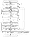
- FIG. 4 is a flow chart showing the operation necessity determination process for the electric oil pump EP.
- step S101 the determination module 332 of the motor control unit 33 determines whether or not the vehicle is decelerating based on the signal output from the acceleration sensor 271. If the vehicle is decelerating (Yes), the process proceeds to step S102. On the other hand, if the vehicle is not decelerating (No), step S101 is repeated.
- step S102 the determination module 332 determines whether the deceleration D of the vehicle detected by the acceleration sensor 271 is greater than or equal to the first deceleration D1. If the deceleration D of the vehicle is greater than or equal to the first deceleration D1 (Yes), the process proceeds to step S103. On the other hand, if the deceleration D of the vehicle is less than the first deceleration D1 (No), the process proceeds to step S111.
- step S103 the engine rotation speed sensor 272 detects the rotation speed of the engine ENG, outputs the detected rotation speed of the engine ENG to the motor control section 33 via the input interface 29, and proceeds to step S104.
- step S104 the determination module 332 determines whether or not the rotation speed of the engine ENG detected by the engine rotation speed sensor 272 is equal to or lower than a predetermined rotation speed. If the rotation speed of the engine ENG is equal to or lower than the predetermined rotation speed (Yes), the process proceeds to step S105. On the other hand, if the rotation speed of the engine ENG exceeds the predetermined rotation speed (No), the process returns to step S103.
- step S105 the oil temperature sensor 273 detects the oil temperature T of the vehicle, outputs the detected oil temperature T of the vehicle to the motor control unit 33 via the input interface 29, and proceeds to step S106.
- step S106 the determination module 332 determines whether or not the vehicle oil temperature T detected by the oil temperature sensor 273 is equal to or higher than the first oil temperature T1. If the oil temperature T of the vehicle is equal to or higher than the first oil temperature T1 (Yes), the process proceeds to step S107. On the other hand, when the vehicle oil temperature T is lower than the first oil temperature T1 (No), the process proceeds to step S111.
- step S107 the determination module 332 determines whether or not the vehicle oil temperature T detected by the oil temperature sensor 273 is between the first oil temperature T1 and the second oil temperature T2. If the vehicle oil temperature T is between the first oil temperature T1 and the second oil temperature T2 (Yes), the process proceeds to step S108. On the other hand, if the oil temperature T of the vehicle exceeds the second oil temperature T2 (No), the process proceeds to step S110.
- step S108 the second deceleration determination module 331 obtains the second deceleration D2 based on the oil temperature T of the vehicle detected by the oil temperature sensor 273, and proceeds to step S109. Specifically, in step S108, the second deceleration determination module 331 determines the second deceleration D2 based on the oil temperature T of the vehicle and the predetermined function equation f(T) stored in advance in the storage unit 31. demand. The second deceleration determination module 331 then outputs the determined second deceleration D2 to the determination module 332 .
- step S109 the determination module 332 of the motor control unit 33 determines whether or not the deceleration D of the vehicle is equal to or less than the second deceleration D2. If the deceleration D of the vehicle is equal to or less than the second deceleration D2 (Yes), the process proceeds to step S110. On the other hand, if the deceleration D of the vehicle exceeds the second deceleration D2 (No), the process proceeds to step S111.
- step S110 the motor control unit 33 drives the electric motor M so as to supply hydraulic pressure from the electric oil pump EP to the transmission TM.
- the command generation module 333 of the motor control unit 33 generates an oil supply command based on the No determination in step S107 or the Yes determination in step S109.
- the command generation module 333 then outputs the generated oil supply command to the electric motor M via the output interface 30 .
- the electric motor M is driven based on the oil supply command output from the command generation module 333, and operates the electric oil pump EP to supply hydraulic pressure from the electric oil pump EP to the transmission TM. Then, this process is terminated.
- step S107 that is, if the deceleration D of the vehicle is equal to or greater than the first deceleration D1 and the oil temperature T of the vehicle exceeds the second oil temperature T2, the motor control unit 33 controls the electric oil Even if the electric motor M is driven so as to supply hydraulic pressure from the pump EP to the transmission TM, the electric oil pump EP does not suck air. Therefore, there is no effect on the transmission TM due to air suction by the electric oil pump EP. Therefore, even if the deceleration D of the vehicle is large, the driving of the electric oil pump EP is not restricted. It is possible to smoothly shift the speed of the vehicle. As a result, it is possible to obtain the reduction gear ratio necessary for starting the vehicle when the vehicle is stopped, so that the acceleration when starting the vehicle can be obtained.
- step S109 that is, the vehicle oil temperature T is between the first oil temperature T1 and the second oil temperature T2, and the vehicle deceleration D is the first deceleration D1 and the second deceleration D2, even if the motor control unit 33 drives the electric motor M so as to supply hydraulic pressure from the electric oil pump EP to the transmission TM, the electric oil pump EP does not suck air. Therefore, there is no effect on the transmission TM due to air suction by the electric oil pump EP.
- step S111 the motor control unit 33 limits the driving of the electric motor M so that hydraulic pressure is not supplied from the electric oil pump EP to the transmission TM.
- the command generation module 333 generates an oil non-supply command based on the No determination in step S104, the No determination in step S106, or the No determination in step S109.
- the command generation module 333 then outputs the generated oil non-supply command to the electric motor M via the output interface 30 .
- the driving of the electric motor M is restricted based on the oil non-supply command output from the command generation module 333, and by not operating the electric oil pump EP, hydraulic pressure is not supplied from the electric oil pump EP to the transmission TM. .
- the engine ENG is controlled to increase its rotational speed. Then, this process is terminated.
- step S104 that is, if the deceleration D of the vehicle is less than the first deceleration D1, the drive of the electric motor M is restricted so as not to supply hydraulic pressure from the electric oil pump EP to the transmission TM. It is possible to prevent deterioration in the durability of the electric oil pump EP due to excessive frequency of use of the electric oil pump EP.
- step S106 that is, if the oil temperature T of the vehicle is lower than the first oil temperature T1, the driving of the electric motor M is restricted so that the oil pressure is not supplied from the electric oil pump EP to the transmission TM. Therefore, it is possible to prevent the durability of the electric oil pump EP from deteriorating due to excessive frequency of use of the electric oil pump EP.
- step S109 that is, if the vehicle oil temperature T is between the first oil temperature T1 and the second oil temperature T2 and the vehicle deceleration D exceeds the second deceleration D2,
- the electric motor M is driven to operate the electric oil pump EP, the electric oil pump EP sucks air. Therefore, the driving of the electric motor M is restricted so as not to supply hydraulic pressure from the electric oil pump EP to the transmission TM. As a result, the influence of the air suction of the electric oil pump EP on the transmission TM can be reduced. Further, in response to subsequent acceleration requests, a higher driving force can be transmitted than when the electric oil pump EP is actuated, so that the sense of discomfort given to the driver can be reduced.
- the vehicle controller 2 (control device) includes a mechanical oil pump MP (first oil pump) driven by an engine ENG (first drive source) that drives the drive wheels DW, and an electric motor.
- An electric oil pump EP (second oil pump) driven by an M (second drive source) and a transmission TM having an engine ENG (first drive source).
- the rotation speed of the motor M (second drive source) is supplied to the transmission TM from the electric oil pump EP (second oil pump) when the rotation speed of the motor M drops below a predetermined rotation speed due to deceleration of the vehicle. is controlled, and the electric motor M ( second drive source).
- a vehicle control method includes a mechanical oil pump MP (first oil pump) driven by an engine ENG (first drive source) that drives drive wheels DW, an electric motor M (second A control method for a vehicle having a transmission TM having an electric oil pump EP (second oil pump) driven by a drive source), wherein the rotation speed of the engine ENG (first drive source) is reduced by deceleration of the vehicle.
- the electric motor M (second drive source) is controlled so as not to supply hydraulic pressure from the electric oil pump EP (second oil pump) to the transmission TM. and limiting the drive.
- the program according to the present embodiment includes a mechanical oil pump MP (first oil pump) driven by an engine ENG (first drive source) that drives the drive wheels DW, and an electric motor M (second drive source).
- a computer-executable program for controlling a vehicle comprising a transmission TM having an electric oil pump EP (second oil pump) driven by a procedure for controlling the drive of the electric motor M (second drive source) so that hydraulic pressure is supplied from the electric oil pump EP (second oil pump) to the transmission TM when the rotation speed drops below a predetermined rotational speed due to the deceleration of , when the deceleration D of the vehicle exceeds the second deceleration D2 (predetermined deceleration), the electric motor M (second driving causes the computer to perform a procedure for restricting the driving of the power source);
- the electric motor M if the electric motor M is driven to operate the electric oil pump EP when the deceleration D of the vehicle exceeds the second deceleration D2, the electric oil pump EP sucks air.
- the driving of the electric motor M is restricted so as not to supply oil pressure from the electric oil pump EP to the transmission TM.
- the influence of the air suction of the electric oil pump EP on the transmission TM can be reduced.
- a higher driving force can be transmitted than when the electric oil pump EP is actuated, so that the sense of discomfort given to the driver can be reduced.
- the second deceleration D2 (predetermined deceleration) changes according to the oil temperature T.
- the controller 2 supplies hydraulic pressure from the electric oil pump EP (second oil pump) to the transmission TM when the oil temperature T is equal to or higher than a second oil temperature T2 (predetermined oil temperature).
- the drive of the electric motor M (second drive source) is controlled as follows.
- the motor control unit 33 drives the electric motor M so as to supply hydraulic pressure from the electric oil pump EP to the transmission TM. Also, since the electric oil pump EP does not suck air, there is no effect on the transmission TM due to the air sucked by the electric oil pump EP. Therefore, even if the deceleration D of the vehicle is large, the driving of the electric oil pump EP is not restricted, so even if the vehicle speed drops while the deceleration D of the vehicle is large, the oil amount can be prevented from decreasing. , the vehicle can be smoothly shifted. As a result, it is possible to obtain the reduction gear ratio necessary for starting the vehicle when the vehicle is stopped, so that the acceleration when starting the vehicle can be obtained.
- the first oil pump and the second oil pump are composed of the mechanical oil pump MP and the electric oil pump EP, respectively. It may be composed of an EP.
Landscapes
- Engineering & Computer Science (AREA)
- General Engineering & Computer Science (AREA)
- Mechanical Engineering (AREA)
- Oil, Petroleum & Natural Gas (AREA)
- Control Of Transmission Device (AREA)
Abstract
[Problem] To provide a vehicle control device and a vehicle control method with which it is possible to reduce the effect on the transmission due to air suction of an electric oil pump. [Solution] A vehicle control device, which comprises a belt continuously variable transmission having a mechanical oil pump driven by an engine that drives drive wheels and an electric oil pump driven by an electric motor, controls the driving of the electric motor so that hydraulic pressure is supplied from the electric oil pump to the belt continuously variable transmission when the rotation speed of the engine falls to or below a predetermined rotation speed due to deceleration of the vehicle, and limits the driving of the electric motor so that hydraulic pressure is not supplied from the electric oil pump to the belt continuously variable transmission when the deceleration rate of the vehicle exceeds a predetermined deceleration rate.
Description
本発明は、車両の制御装置、車両の制御方法及びプログラムに関する。
The present invention relates to a vehicle control device, a vehicle control method, and a program.
特許文献1には、ポンプ駆動制御手段は、減速要求検出手段によって検出される減速要求が大きくなるにつれて、車速検出手段によって検出される車速が高い車速で、電動オイルポンプの駆動を開始するように電動オイルポンプの駆動を制御することが開示されている。
In Patent Document 1, a pump drive control means starts driving an electric oil pump at a vehicle speed detected by a vehicle speed detecting means as the deceleration request detected by the deceleration request detecting means increases. Controlling the drive of an electric oil pump is disclosed.
しかしながら、特許文献1に記載の発明では、車両の減速度が大きい場合に、電動オイルポンプがエアを吸い込んでしまうため、停止後に運転者から発進要求があった場合や、減速中に運転者から加速要求があった場合に、車両の加速するタイミングが遅れ、運転者に違和感を与えるおそれがある。
However, in the invention described in Patent Document 1, when the deceleration of the vehicle is large, the electric oil pump sucks in air. When there is an acceleration request, the timing of accelerating the vehicle is delayed, which may give the driver a sense of discomfort.
本発明は、このような課題に鑑みてなされたもので、電動オイルポンプのエア吸いによる変速機への影響を低減することができる車両の制御装置、車両の制御方法及びプログラムを提供することを目的とする。
SUMMARY OF THE INVENTION It is an object of the present invention to provide a vehicle control device, a vehicle control method, and a program capable of reducing the influence of air suction by an electric oil pump on a transmission. aim.
本発明のある態様によれば、駆動輪を駆動する第1駆動源によって駆動される第1オイルポンプと、第2駆動源によって駆動される第2オイルポンプと、を有する変速機を備える車両の制御装置であって、前記第1駆動源の回転速度が前記車両の減速により所定回転速度以下になった場合に、前記第2オイルポンプから前記変速機に油圧を供給するように前記第2駆動源の駆動を制御し、前記車両の減速度が所定減速度を上回る場合に、前記第2オイルポンプから前記変速機に油圧を供給しないように前記第2駆動源の駆動を制限する車両の制御装置が提供される。
According to an aspect of the present invention, a vehicle including a transmission having a first oil pump driven by a first drive source that drives drive wheels and a second oil pump driven by a second drive source In the control device, when the rotation speed of the first drive source becomes equal to or lower than a predetermined rotation speed due to deceleration of the vehicle, the second drive is configured to supply hydraulic pressure from the second oil pump to the transmission. control the drive of the second drive source, and limit the drive of the second drive source so that hydraulic pressure is not supplied from the second oil pump to the transmission when the deceleration of the vehicle exceeds a predetermined deceleration; An apparatus is provided.
本発明の他の態様によれば、駆動輪を駆動する第1駆動源によって駆動される第1オイルポンプと、第2駆動源によって駆動される第2オイルポンプと、を有する変速機を備える車両の制御方法であって、前記第1駆動源の回転速度が前記車両の減速により所定回転速度以下になった場合に、前記第2オイルポンプから前記変速機に油圧を供給するように前記第2駆動源の駆動を制御するステップと、前記車両の減速度が所定減速度を上回る場合に、前記第2オイルポンプから前記変速機に油圧を供給しないように前記第2駆動源の駆動を制限するステップと、を含む車両の制御方法が提供される。
According to another aspect of the present invention, a vehicle including a transmission having a first oil pump driven by a first drive source that drives drive wheels and a second oil pump driven by a second drive source In the control method of 1, when the rotation speed of the first drive source becomes equal to or lower than a predetermined rotation speed due to deceleration of the vehicle, the second oil pump supplies hydraulic pressure to the transmission. controlling the drive of the drive source; and limiting the drive of the second drive source so that hydraulic pressure is not supplied from the second oil pump to the transmission when deceleration of the vehicle exceeds a predetermined deceleration. A method for controlling a vehicle is provided, comprising the steps of:
本発明のその他の態様によれば、駆動輪を駆動する第1駆動源によって駆動される第1オイルポンプと、第2駆動源によって駆動される第2オイルポンプと、を有する変速機を備える車両を制御するコンピュータが実行可能なプログラムであって、前記第1駆動源の回転速度が前記車両の減速により所定回転速度以下になった場合に、前記第2オイルポンプから前記変速機に油圧を供給するように前記第2駆動源の駆動を制御する手順と、前記車両の減速度が所定減速度を上回る場合に、前記第2オイルポンプから前記変速機に油圧を供給しないように前記第2駆動源の駆動を制限する手順と、を前記コンピュータに実行させるプログラムが提供される。
According to another aspect of the present invention, a vehicle including a transmission having a first oil pump driven by a first drive source that drives drive wheels and a second oil pump driven by a second drive source A computer-executable program that controls the second oil pump to supply hydraulic pressure to the transmission when the rotation speed of the first drive source falls below a predetermined rotation speed due to deceleration of the vehicle and a procedure for controlling the drive of the second drive source so that the second drive source does not supply hydraulic pressure from the second oil pump to the transmission when deceleration of the vehicle exceeds a predetermined deceleration. A program is provided which causes the computer to perform a procedure for limiting the drive of the source.
これらの態様によれば、電動オイルポンプのエア吸いによる変速機への影響を低減することができる。
According to these aspects, it is possible to reduce the influence of the air suction of the electric oil pump on the transmission.
以下、添付図面を参照しながら本発明の実施形態(以下、本実施形態という)について説明する。
An embodiment of the present invention (hereinafter referred to as the present embodiment) will be described below with reference to the accompanying drawings.
(変速機の構成)
まず、図1を参照しながら本実施形態に係る変速機TMについて説明する。 (Configuration of transmission)
First, the transmission TM according to this embodiment will be described with reference to FIG.
まず、図1を参照しながら本実施形態に係る変速機TMについて説明する。 (Configuration of transmission)
First, the transmission TM according to this embodiment will be described with reference to FIG.
図1は、車両の概略構成図である。
Fig. 1 is a schematic configuration diagram of a vehicle.
図1に示すように、車両は、第1駆動源としてのエンジンENGとトルクコンバータTCと前後進切替機構SWMとバリエータVAとを備える。車両では、変速機TMがトルクコンバータTCと前後進切替機構SWMとバリエータVAとを有するベルト無段変速機とされる。
As shown in FIG. 1, the vehicle includes an engine ENG as a first drive source, a torque converter TC, a forward/reverse switching mechanism SWM, and a variator VA. In the vehicle, the transmission TM is a continuously variable belt transmission having a torque converter TC, a forward/reverse switching mechanism SWM, and a variator VA.
エンジンENGは、車両の駆動源を構成する。エンジンENGの動力は、トルクコンバータTC、前後進切替機構SWM、バリエータVAを介して駆動輪DWへと伝達される。換言すれば、トルクコンバータTC、前後進切替機構SWM、バリエータVAは、エンジンENGと駆動輪DWとを結ぶ動力伝達経路に設けられる。
The engine ENG constitutes the drive source of the vehicle. The power of the engine ENG is transmitted to the drive wheels DW via the torque converter TC, the forward/reverse switching mechanism SWM, and the variator VA. In other words, torque converter TC, forward/reverse switching mechanism SWM, and variator VA are provided in a power transmission path connecting engine ENG and drive wheels DW.
トルクコンバータTCは、流体を介して動力を伝達する。トルクコンバータTCでは、ロックアップクラッチLUを締結することで、動力伝達効率が高められる。
The torque converter TC transmits power through fluid. In the torque converter TC, the power transmission efficiency is enhanced by engaging the lockup clutch LU.
前後進切替機構SWMは、エンジンENGとバリエータVAとを結ぶ動力伝達経路に設けられる。前後進切替機構SWMは、入力される回転の回転方向を切り替えることで車両の前後進を切り替える。前後進切替機構SWMは、前進レンジ選択の際に係合される前進クラッチFWD/Cと、リバースレンジ選択の際に係合される後進ブレーキREV/Bとを備える。前進クラッチFWD/C及び後進ブレーキREV/Bを解放すると、変速機TMがニュートラル状態、つまり動力遮断状態になる。
The forward/reverse switching mechanism SWM is provided in the power transmission path connecting the engine ENG and the variator VA. The forward/reverse switching mechanism SWM switches the forward/rearward movement of the vehicle by switching the rotation direction of the input rotation. The forward/reverse switching mechanism SWM includes a forward clutch FWD/C that is engaged when the forward range is selected, and a reverse brake REV/B that is engaged when the reverse range is selected. When the forward clutch FWD/C and the reverse brake REV/B are released, the transmission TM is put into a neutral state, that is, a power cutoff state.
バリエータVAは、プライマリプーリPRIと、セカンダリプーリSECと、プライマリプーリPRI及びセカンダリプーリSECに巻き掛けられたベルトBLTとを有するベルト無段変速機構を構成する。プライマリプーリPRIにはプライマリプーリPRIの油圧であるプライマリプーリ圧Ppriが、セカンダリプーリSECにはセカンダリプーリSECの油圧であるセカンダリプーリ圧Psecが、後述する油圧制御回路1からそれぞれ供給される。
The variator VA constitutes a belt continuously variable transmission mechanism having a primary pulley PRI, a secondary pulley SEC, and a belt BLT wound around the primary pulley PRI and the secondary pulley SEC. A primary pulley pressure Ppri, which is the hydraulic pressure of the primary pulley PRI, is supplied to the primary pulley PRI, and a secondary pulley pressure Psec, which is the hydraulic pressure of the secondary pulley SEC, is supplied from the hydraulic control circuit 1, which will be described later.
変速機TMは、第1オイルポンプとしてのメカニカルオイルポンプMPと、第2オイルポンプとしての電動オイルポンプEPと、第2駆動源としての電動モータMと、をさらに有して構成される。
The transmission TM further includes a mechanical oil pump MP as a first oil pump, an electric oil pump EP as a second oil pump, and an electric motor M as a second drive source.
メカニカルオイルポンプMPは、油圧制御回路1に油を圧送(供給)する。メカニカルオイルポンプMPと油圧制御回路1とを連通する流路には、逆止弁25が設けられる。メカニカルオイルポンプMPは、エンジンENGの動力により駆動される。
The mechanical oil pump MP pumps (supplies) oil to the hydraulic control circuit 1. A check valve 25 is provided in a flow path that communicates the mechanical oil pump MP and the hydraulic control circuit 1 . Mechanical oil pump MP is driven by the power of engine ENG.
電動オイルポンプEPは、メカニカルオイルポンプMPとともに、或いは単独で油圧制御回路1に油を圧送(供給)する。電動オイルポンプEPと油圧制御回路1とを連通する流路には、逆止弁26が設けられる。電動オイルポンプEPは、メカニカルオイルポンプMPに対して補助的に設けられる。すなわち、電動オイルポンプEPは、メカニカルオイルポンプMPから変速機TMへの油の供給が停止又は不足した場合に不足分の油を補うように駆動要求に基づいて一時的に変速機TMに油を供給する。電動モータMは電動オイルポンプEPを駆動する。電動オイルポンプEPは電動モータMを有して構成されると把握されてもよい。
The electric oil pump EP pressure-feeds (supplies) oil to the hydraulic control circuit 1 together with the mechanical oil pump MP or independently. A check valve 26 is provided in a flow path that communicates the electric oil pump EP and the hydraulic control circuit 1 . The electric oil pump EP is provided auxiliary to the mechanical oil pump MP. That is, the electric oil pump EP temporarily supplies oil to the transmission TM based on the drive demand so as to compensate for the shortage of oil when the supply of oil from the mechanical oil pump MP to the transmission TM is stopped or runs short. supply. An electric motor M drives an electric oil pump EP. It may be understood that the electric oil pump EP is configured with an electric motor M.
変速機TMは、油圧制御回路1と車両の制御装置としてのコントローラ2とをさらに有して構成される。油圧制御回路1は複数の流路、複数の油圧制御弁で構成され、メカニカルオイルポンプMPや電動オイルポンプEPから供給される油を調圧して変速機TMの各部位に供給する。
The transmission TM further includes a hydraulic control circuit 1 and a controller 2 as a vehicle control device. The hydraulic control circuit 1 includes a plurality of flow paths and a plurality of hydraulic control valves, regulates the pressure of oil supplied from the mechanical oil pump MP and the electric oil pump EP, and supplies the oil to each part of the transmission TM.
また、車両は、各種センサ27をさらに備える。各種センサ27は、車両の加速度又は減速度を検出する加速度検出手段としての加速度センサ271と、エンジン回転速度を検出するエンジン回転速度検出手段としてのエンジン回転速度センサ272と、油温を検出する油温検出手段としての油温センサ273とを有する。
In addition, the vehicle further includes various sensors 27. The various sensors 27 include an acceleration sensor 271 as acceleration detection means for detecting acceleration or deceleration of the vehicle, an engine rotation speed sensor 272 as engine rotation speed detection means for detecting the engine rotation speed, and an oil temperature sensor for detecting oil temperature. It has an oil temperature sensor 273 as temperature detection means.
コントローラ2は、変速機TMを制御するためのコントローラであり、各種センサ27等から出力される信号に基づき油圧制御回路1や電動オイルポンプEPを駆動する電動モータMを制御する。本実施形態では、コントローラ2は、コンピュータとしてのCPUにより構成されているが、これに限定されるものではなく、例えば、複数のマイクロコンピュータにより構成されてもよい。なお、コントローラ2の詳細については後述する。
The controller 2 is a controller for controlling the transmission TM, and controls the hydraulic control circuit 1 and the electric motor M that drives the electric oil pump EP based on signals output from various sensors 27 and the like. In this embodiment, the controller 2 is composed of a CPU as a computer, but is not limited to this, and may be composed of, for example, a plurality of microcomputers. Details of the controller 2 will be described later.
油圧制御回路1は、コントローラ2からの指令に基づき、ロックアップクラッチLU、前進クラッチFWD/C、後進ブレーキREV/B、プライマリプーリPRI、セカンダリプーリSEC等の油圧制御を行う。
Based on commands from the controller 2, the hydraulic control circuit 1 performs hydraulic control of the lockup clutch LU, forward clutch FWD/C, reverse brake REV/B, primary pulley PRI, secondary pulley SEC, and the like.
(コントローラの構成)
次に、図2を参照しながらコントローラ2について説明する。 (Controller configuration)
Next, thecontroller 2 will be described with reference to FIG.
次に、図2を参照しながらコントローラ2について説明する。 (Controller configuration)
Next, the
図2は、コントローラ2及びコントローラ2に接続される主要構成を示す構成ブロック図である。
FIG. 2 is a configuration block diagram showing the main configuration connected to the controller 2 and the controller 2. As shown in FIG.
図2に示すように、コントローラ2は、互いに電気的に接続される入力インタフェース29、出力インタフェース30、記憶部31、油圧制御回路制御部32(以下、単に回路制御部32という)及び電動モータ制御部33(以下、単にモータ制御部33という)を備える。
As shown in FIG. 2, the controller 2 includes an input interface 29, an output interface 30, a storage unit 31, a hydraulic control circuit control unit 32 (hereinafter simply referred to as circuit control unit 32), and an electric motor control unit, which are electrically connected to each other. A section 33 (hereinafter simply referred to as a motor control section 33) is provided.
入力インタフェース29には、各種パラメータを検出する各種センサ27からの出力信号が入力される。
Output signals from various sensors 27 that detect various parameters are input to the input interface 29 .
回路制御部32の処理により生成された回路制御指令及びモータ制御部33の処理により生成されたモータ制御指令は、出力インタフェース30を介してそれぞれ油圧制御回路1及び電動モータMに出力される。
The circuit control command generated by the processing of the circuit control unit 32 and the motor control command generated by the processing of the motor control unit 33 are output to the hydraulic control circuit 1 and the electric motor M via the output interface 30, respectively.
記憶部31は、各種センサ27からの出力信号に含まれる各種パラメータを一時的に記憶するためのメモリである。また、記憶部31は、回路制御部32及びモータ制御部33において実行される処理プログラム及びアルゴリズムプログラムを記憶している。本実施形態では、記憶部31は、コントローラ2に内蔵されているが、これに限定されるものではなく、例えば、コントローラ2とは別体に設けられてもよい。
The storage unit 31 is a memory for temporarily storing various parameters included in output signals from the various sensors 27 . The storage unit 31 also stores processing programs and algorithm programs executed by the circuit control unit 32 and the motor control unit 33 . Although the storage unit 31 is built in the controller 2 in the present embodiment, the storage unit 31 is not limited to this, and may be provided separately from the controller 2, for example.
また、記憶部31は、電動オイルポンプEPの作動要否判定処理に用いられる所定回転速度、第1減速度D1、第1油温T1、所定油温としての第2油温T2及び所定減速度としての第2減速度D2を求めるための所定関数方程式f(T)を記憶している。なお、第1減速度D1、第1油温T1、第2油温T2及び第2減速度D2を求めるための所定関数方程式f(T)については後述する。
Further, the storage unit 31 stores a predetermined rotation speed, a first deceleration D1, a first oil temperature T1, a second oil temperature T2 as a predetermined oil temperature, and a predetermined deceleration, which are used in the operation necessity determination process of the electric oil pump EP. A predetermined function equation f(T) for obtaining the second deceleration D2 as . A predetermined function equation f(T) for obtaining the first deceleration D1, the first oil temperature T1, the second oil temperature T2, and the second deceleration D2 will be described later.
回路制御部32は、各種センサ27から出力される出力信号に基づいて回路制御指令を生成し、生成した回路制御指令を出力インタフェース30を介して油圧制御回路1に出力する。
The circuit control unit 32 generates circuit control commands based on output signals output from the various sensors 27 and outputs the generated circuit control commands to the hydraulic control circuit 1 via the output interface 30 .
モータ制御部33は、各種センサ27から出力される出力信号に基づいてモータ制御指令を生成し、生成したモータ制御指令を出力インタフェース30を介して電動モータMに出力する。
The motor control unit 33 generates a motor control command based on output signals output from the various sensors 27 and outputs the generated motor control command to the electric motor M via the output interface 30 .
また、モータ制御部33は、第2減速度決定手段としての第2減速度決定モジュール331、判定手段としての判定モジュール332及び指令生成手段としての指令生成モジュール333を有する。なお、第2減速度決定モジュール331、判定モジュール332及び指令生成モジュール333の詳細については、電動オイルポンプEPの作動要否判定処理において後述する。
The motor control unit 33 also has a second deceleration determination module 331 as second deceleration determination means, a determination module 332 as determination means, and a command generation module 333 as command generation means. The details of the second deceleration determination module 331, the determination module 332, and the command generation module 333 will be described later in the operation necessity determination process for the electric oil pump EP.
(電動オイルポンプの作動領域及び非作動領域の説明)
次に、図3を参照しながら電動オイルポンプEPの作動領域及び非作動領域について説明する。 (Description of the operation area and non-operation area of the electric oil pump)
Next, the operating region and non-operating region of the electric oil pump EP will be described with reference to FIG.
次に、図3を参照しながら電動オイルポンプEPの作動領域及び非作動領域について説明する。 (Description of the operation area and non-operation area of the electric oil pump)
Next, the operating region and non-operating region of the electric oil pump EP will be described with reference to FIG.
図3は油温T及び減速度Dからなるテーブルに電動オイルポンプEPの作動領域及び電動オイルポンプEPの非作動領域を示す図である。図3において、車両の油温T及び車両の減速度Dをそれぞれ横軸及び縦軸とする。図3における×は、実験によりエア吸いが発生したことを示している。
Fig. 3 is a diagram showing the operating region of the electric oil pump EP and the non-operating region of the electric oil pump EP in a table consisting of the oil temperature T and the deceleration D. In FIG. 3, the horizontal axis and the vertical axis represent the vehicle oil temperature T and the vehicle deceleration D, respectively. X in FIG. 3 indicates that air suction occurred in the experiment.
図3に示すように、車両の減速度(具体的には、最大減速度)Dが第1減速度D1を下回る場合は、電動オイルポンプEPがエアを吸い込まないが、メカニカルオイルポンプMPから供給される油で必要な油量を確保することができる。このため、車両の減速度Dが第1減速度D1を下回る領域を電動オイルポンプEPの非作動領域とする。なお、第1減速度D1は、車両の油温Tによって変化しない不変値である。本実施形態では、第1減速度D1は、不変値となっているが変更するようにしてもよい。
As shown in FIG. 3, when the vehicle deceleration (specifically, the maximum deceleration) D is less than the first deceleration D1, the electric oil pump EP does not suck air, but air is supplied from the mechanical oil pump MP. It is possible to secure the necessary amount of oil with the oil that is used. Therefore, the region where the deceleration D of the vehicle is lower than the first deceleration D1 is defined as the non-operating region of the electric oil pump EP. Note that the first deceleration D1 is a constant value that does not change with the oil temperature T of the vehicle. In this embodiment, the first deceleration D1 is a fixed value, but may be changed.
車両の油温Tが第1油温T1を下回る場合は、やはり、メカニカルオイルポンプMPから供給される油で必要な油量を確保することができる。このため、車両の油温Tが第1油温T1を下回る領域を電動オイルポンプEPの非作動領域とする。なお、第1油温T1は、減速度Dによって変化しない不変値である。本実施形態では、第1油温T1は、不変値となっているが変更するようにしてもよい。
When the oil temperature T of the vehicle is lower than the first oil temperature T1, the necessary amount of oil can be secured with the oil supplied from the mechanical oil pump MP. Therefore, the region where the oil temperature T of the vehicle is lower than the first oil temperature T1 is defined as the non-operating region of the electric oil pump EP. Note that the first oil temperature T1 is a constant value that does not change with the deceleration D. In this embodiment, the first oil temperature T1 is a fixed value, but may be changed.
車両の減速度が第1減速度D1以上であり、かつ、車両の油温Tが第1油温T1よりも大きい第2油温T2以上である場合に、車両の減速度Dが大きくても電動オイルポンプEPがエアを吸い込まない。このため、車両の減速度が第1減速度D1以上であり、かつ、車両の油温Tが第2油温T2以上である領域を電動オイルポンプEPの作動領域とする。なお、第2油温T2は、減速度Dによって変化しない不変値である。本実施形態では、第2油温T2は、不変値となっているが変更するようにしてもよい。
When the deceleration of the vehicle is equal to or higher than the first deceleration D1 and the oil temperature T of the vehicle is equal to or higher than the second oil temperature T2 which is higher than the first oil temperature T1, even if the deceleration D of the vehicle is large, Electric oil pump EP does not suck air. Therefore, the region where the deceleration of the vehicle is equal to or higher than the first deceleration D1 and the oil temperature T of the vehicle is equal to or higher than the second oil temperature T2 is defined as the operation region of the electric oil pump EP. The second oil temperature T2 is a constant value that does not change with the deceleration D. In this embodiment, the second oil temperature T2 is a fixed value, but may be changed.
車両の油温Tが第1油温T1と第2油温T2との間にあり、かつ、車両の減速度Dが第1減速度D1よりも大きい所定減速度としての第2減速度D2を上回る場合に、電動オイルポンプEPがエアを吸い込んでしまう。このため、車両の油温Tが第1油温T1と第2油温T2との間にあり、かつ、車両の減速度が第2減速度D2を上回る領域を電動オイルポンプEPの非作動領域とする。
A second deceleration D2 is set as a predetermined deceleration in which the oil temperature T of the vehicle is between the first oil temperature T1 and the second oil temperature T2 and the deceleration D of the vehicle is greater than the first deceleration D1. If it exceeds, the electric oil pump EP will suck air. Therefore, the non-operating region of the electric oil pump EP is defined as the region where the oil temperature T of the vehicle is between the first oil temperature T1 and the second oil temperature T2 and the deceleration of the vehicle exceeds the second deceleration D2. and
なお、第2減速度D2は、車両の油温Tによって変化する可変値である。これにより、第2減速度D2が車両の油温Tによって変化しない不変値である場合に比べ、電動オイルポンプEPの作動領域を大きくすることができる。
Note that the second deceleration D2 is a variable value that changes depending on the oil temperature T of the vehicle. As a result, compared to the case where the second deceleration D2 is a constant value that does not change with the oil temperature T of the vehicle, the operating range of the electric oil pump EP can be increased.
具体的には、図3に示すように、車両の油温Tが高いほど車両の減速度Dが大きくても電動オイルポンプEPがエアを吸いにくくなるため、第2減速度D2は、車両の油温Tが高いほど大きくなるように決定される。これにより、車両の油温Tが高い場合は、より電動オイルポンプEPを駆動しやすくなり、車速が低下しても油量が低下することを抑制することができるため、車両の変速をスムーズに行うことができる。この結果、車両の停車時に発進に必要な減速比を得ることができるため、車両の発進時の加速を得ることができる。より具体的には、第2減速度D2は、車両の油温T及びあらかじめ設定される所定関数方程式f(T)に基づいて求められる(決定される)。本実施形態では、第2減速度D2は、車両の油温Tが高くなるに従って大きくなるように変動している。
Specifically, as shown in FIG. 3, the higher the oil temperature T of the vehicle, the more difficult it is for the electric oil pump EP to suck air even if the deceleration D of the vehicle increases. It is determined so that the higher the oil temperature T is, the larger it becomes. As a result, when the oil temperature T of the vehicle is high, it becomes easier to drive the electric oil pump EP, and even if the vehicle speed decreases, the amount of oil can be suppressed from decreasing, so that the vehicle can smoothly shift gears. It can be carried out. As a result, it is possible to obtain the reduction gear ratio necessary for starting the vehicle when the vehicle is stopped, so that the acceleration when starting the vehicle can be obtained. More specifically, the second deceleration D2 is obtained (determined) based on the oil temperature T of the vehicle and a preset function equation f(T). In this embodiment, the second deceleration D2 fluctuates so as to increase as the oil temperature T of the vehicle increases.
一方、車両の油温Tが第1油温T1と第2油温T2との間にあり、かつ、車両の減速度Dが第1減速度D1と第2減速度D2との間にある場合に、電動オイルポンプEPがエアを吸い込まない。このため、車両の油温Tが第1油温T1と第2油温T2との間にあり、かつ、車両の減速度Dが第1減速度D1と第2減速度D2との間にある領域を電動オイルポンプEPの作動領域とする。
On the other hand, when the oil temperature T of the vehicle is between the first oil temperature T1 and the second oil temperature T2, and the deceleration D of the vehicle is between the first deceleration D1 and the second deceleration D2. Secondly, the electric oil pump EP does not suck in air. Therefore, the oil temperature T of the vehicle is between the first oil temperature T1 and the second oil temperature T2, and the deceleration D of the vehicle is between the first deceleration D1 and the second deceleration D2. The area is assumed to be the operation area of the electric oil pump EP.
(電動オイルポンプの作動要否判定処理)
次に、図4を参照しながら電動オイルポンプEPの作動要否判定処理について説明する。 (Determining the need to operate the electric oil pump)
Next, the operation necessity determination process for the electric oil pump EP will be described with reference to FIG.
次に、図4を参照しながら電動オイルポンプEPの作動要否判定処理について説明する。 (Determining the need to operate the electric oil pump)
Next, the operation necessity determination process for the electric oil pump EP will be described with reference to FIG.
図4は、電動オイルポンプEPの作動要否判定処理を示すフローチャートである。
FIG. 4 is a flow chart showing the operation necessity determination process for the electric oil pump EP.
図4に示すように、まず、ステップS101において、モータ制御部33の判定モジュール332は、加速度センサ271から出力される信号に基づいて車両が減速中であるか否かを判定する。車両が減速中である場合(Yesの場合)は、ステップS102に進む。一方、車両が減速中ではない場合(Noの場合)は、ステップS101を繰り返す。
As shown in FIG. 4, first, in step S101, the determination module 332 of the motor control unit 33 determines whether or not the vehicle is decelerating based on the signal output from the acceleration sensor 271. If the vehicle is decelerating (Yes), the process proceeds to step S102. On the other hand, if the vehicle is not decelerating (No), step S101 is repeated.
次に、ステップS102において、判定モジュール332は、加速度センサ271が検出した車両の減速度Dが第1減速度D1以上であるか否かを判定する。車両の減速度Dが第1減速度D1以上である場合(Yesの場合)は、ステップS103に進む。一方、車両の減速度Dが第1減速度D1を下回る場合(Noの場合)は、ステップS111に進む。
Next, in step S102, the determination module 332 determines whether the deceleration D of the vehicle detected by the acceleration sensor 271 is greater than or equal to the first deceleration D1. If the deceleration D of the vehicle is greater than or equal to the first deceleration D1 (Yes), the process proceeds to step S103. On the other hand, if the deceleration D of the vehicle is less than the first deceleration D1 (No), the process proceeds to step S111.
次に、ステップS103において、エンジン回転速度センサ272は、エンジンENGの回転速度を検出し、検出したエンジンENGの回転速度を入力インタフェース29を介してモータ制御部33に出力し、ステップS104に進む。
Next, in step S103, the engine rotation speed sensor 272 detects the rotation speed of the engine ENG, outputs the detected rotation speed of the engine ENG to the motor control section 33 via the input interface 29, and proceeds to step S104.
次に、ステップS104において、判定モジュール332は、エンジン回転速度センサ272が検出したエンジンENGの回転速度が所定回転速度以下であるか否かを判定する。エンジンENGの回転速度が所定回転速度以下である場合(Yesの場合)は、ステップS105に進む。一方、エンジンENGの回転速度が所定回転速度を上回る場合(Noの場合)は、ステップS103に戻る。
Next, in step S104, the determination module 332 determines whether or not the rotation speed of the engine ENG detected by the engine rotation speed sensor 272 is equal to or lower than a predetermined rotation speed. If the rotation speed of the engine ENG is equal to or lower than the predetermined rotation speed (Yes), the process proceeds to step S105. On the other hand, if the rotation speed of the engine ENG exceeds the predetermined rotation speed (No), the process returns to step S103.
次に、ステップS105において、油温センサ273は、車両の油温Tを検出し、検出した車両の油温Tを入力インタフェース29を介してモータ制御部33に出力し、ステップS106に進む。
Next, in step S105, the oil temperature sensor 273 detects the oil temperature T of the vehicle, outputs the detected oil temperature T of the vehicle to the motor control unit 33 via the input interface 29, and proceeds to step S106.
次に、ステップS106において、判定モジュール332は、油温センサ273が検出した車両の油温Tが第1油温T1以上であるか否かを判定する。車両の油温Tが第1油温T1以上である場合(Yesの場合)は、ステップS107に進む。一方、車両の油温Tが第1油温T1を下回る場合(Noの場合)は、ステップS111に進む。
Next, in step S106, the determination module 332 determines whether or not the vehicle oil temperature T detected by the oil temperature sensor 273 is equal to or higher than the first oil temperature T1. If the oil temperature T of the vehicle is equal to or higher than the first oil temperature T1 (Yes), the process proceeds to step S107. On the other hand, when the vehicle oil temperature T is lower than the first oil temperature T1 (No), the process proceeds to step S111.
次に、ステップS107において、判定モジュール332は、油温センサ273が検出した車両の油温Tが第1油温T1と第2油温T2との間にあるか否かを判定する。車両の油温Tが第1油温T1と第2油温T2との間にある場合(Yesの場合)は、ステップS108に進む。一方、車両の油温Tが第2油温T2を上回る場合(Noの場合)は、ステップS110に進む。
Next, in step S107, the determination module 332 determines whether or not the vehicle oil temperature T detected by the oil temperature sensor 273 is between the first oil temperature T1 and the second oil temperature T2. If the vehicle oil temperature T is between the first oil temperature T1 and the second oil temperature T2 (Yes), the process proceeds to step S108. On the other hand, if the oil temperature T of the vehicle exceeds the second oil temperature T2 (No), the process proceeds to step S110.
次に、ステップS108において、第2減速度決定モジュール331は、油温センサ273が検出した車両の油温Tに基づいて第2減速度D2を求め、ステップS109に進む。具体的には、ステップS108において、第2減速度決定モジュール331は、車両の油温Tとあらかじめ記憶部31に記憶された所定関数方程式f(T)とに基づいて、第2減速度D2を求める。そして、第2減速度決定モジュール331は、求めた第2減速度D2を判定モジュール332に出力する。
Next, in step S108, the second deceleration determination module 331 obtains the second deceleration D2 based on the oil temperature T of the vehicle detected by the oil temperature sensor 273, and proceeds to step S109. Specifically, in step S108, the second deceleration determination module 331 determines the second deceleration D2 based on the oil temperature T of the vehicle and the predetermined function equation f(T) stored in advance in the storage unit 31. demand. The second deceleration determination module 331 then outputs the determined second deceleration D2 to the determination module 332 .
次に、ステップS109において、モータ制御部33の判定モジュール332は、車両の減速度Dが第2減速度D2以下であるか否かを判定する。車両の減速度Dが第2減速度D2以下である場合(Yesの場合)は、ステップS110に進む。一方、車両の減速度Dが第2減速度D2を上回る場合(Noの場合)は、ステップS111に進む。
Next, in step S109, the determination module 332 of the motor control unit 33 determines whether or not the deceleration D of the vehicle is equal to or less than the second deceleration D2. If the deceleration D of the vehicle is equal to or less than the second deceleration D2 (Yes), the process proceeds to step S110. On the other hand, if the deceleration D of the vehicle exceeds the second deceleration D2 (No), the process proceeds to step S111.
次に、ステップS110において、モータ制御部33は、電動オイルポンプEPから変速機TMに油圧を供給するように電動モータMを駆動する。具体的には、ステップS110において、モータ制御部33の指令生成モジュール333は、ステップS107のNo判定、又はステップS109のYes判定に基づいて、油供給指令を生成する。そして、指令生成モジュール333は、生成した油供給指令を出力インタフェース30を介して電動モータMに出力する。そして、電動モータMは、指令生成モジュール333から出力された油供給指令に基づいて駆動され、電動オイルポンプEPを作動することにより、電動オイルポンプEPから変速機TMに油圧を供給する。そして、本処理を終了させる。
Next, in step S110, the motor control unit 33 drives the electric motor M so as to supply hydraulic pressure from the electric oil pump EP to the transmission TM. Specifically, in step S110, the command generation module 333 of the motor control unit 33 generates an oil supply command based on the No determination in step S107 or the Yes determination in step S109. The command generation module 333 then outputs the generated oil supply command to the electric motor M via the output interface 30 . The electric motor M is driven based on the oil supply command output from the command generation module 333, and operates the electric oil pump EP to supply hydraulic pressure from the electric oil pump EP to the transmission TM. Then, this process is terminated.
ステップS107でNoの場合、すなわち、車両の減速度Dが第1減速度D1以上であり、かつ、車両の油温Tが第2油温T2を上回る場合に、モータ制御部33は、電動オイルポンプEPから変速機TMに油圧を供給するように電動モータMを駆動しても、電動オイルポンプEPがエアを吸い込まない。このため、電動オイルポンプEPのエア吸いによる変速機TMへの影響がない。よって、車両の減速度Dが大きくても電動オイルポンプEPの駆動が制限されないため、車両の減速度Dが大きい状態で車速が低下しても油量が低下することを抑制することができ、車両の変速をスムーズに行うことができる。この結果、車両の停車時に発進に必要な減速比を得ることができるため、車両の発進時の加速を得ることができる。
If No in step S107, that is, if the deceleration D of the vehicle is equal to or greater than the first deceleration D1 and the oil temperature T of the vehicle exceeds the second oil temperature T2, the motor control unit 33 controls the electric oil Even if the electric motor M is driven so as to supply hydraulic pressure from the pump EP to the transmission TM, the electric oil pump EP does not suck air. Therefore, there is no effect on the transmission TM due to air suction by the electric oil pump EP. Therefore, even if the deceleration D of the vehicle is large, the driving of the electric oil pump EP is not restricted. It is possible to smoothly shift the speed of the vehicle. As a result, it is possible to obtain the reduction gear ratio necessary for starting the vehicle when the vehicle is stopped, so that the acceleration when starting the vehicle can be obtained.
ステップS109でYesの場合、すなわち、車両の油温Tが第1油温T1と第2油温T2との間にあり、かつ、車両の減速度Dが第1減速度D1と第2減速度D2との間にある場合に、モータ制御部33は、電動オイルポンプEPから変速機TMに油圧を供給するように電動モータMを駆動しても、電動オイルポンプEPがエアを吸い込まない。このため、電動オイルポンプEPのエア吸いによる変速機TMへの影響がない。
If Yes in step S109, that is, the vehicle oil temperature T is between the first oil temperature T1 and the second oil temperature T2, and the vehicle deceleration D is the first deceleration D1 and the second deceleration D2, even if the motor control unit 33 drives the electric motor M so as to supply hydraulic pressure from the electric oil pump EP to the transmission TM, the electric oil pump EP does not suck air. Therefore, there is no effect on the transmission TM due to air suction by the electric oil pump EP.
一方、ステップS111において、モータ制御部33は、電動オイルポンプEPから変速機TMに油圧を供給しないように電動モータMの駆動を制限する。具体的には、ステップS111において、指令生成モジュール333は、ステップS104のNo判定、ステップS106のNo判定、又はS109のNo判定に基づいて、油非供給指令を生成する。そして、指令生成モジュール333は、生成した油非供給指令を出力インタフェース30を介して電動モータMに出力する。そして、電動モータMの駆動は、指令生成モジュール333から出力された油非供給指令に基づいて制限され、電動オイルポンプEPを作動しないことにより、電動オイルポンプEPから変速機TMに油圧を供給しない。この場合に、エンジンENGをその回転数を向上させるように制御する。そして、本処理を終了させる。
On the other hand, in step S111, the motor control unit 33 limits the driving of the electric motor M so that hydraulic pressure is not supplied from the electric oil pump EP to the transmission TM. Specifically, in step S111, the command generation module 333 generates an oil non-supply command based on the No determination in step S104, the No determination in step S106, or the No determination in step S109. The command generation module 333 then outputs the generated oil non-supply command to the electric motor M via the output interface 30 . The driving of the electric motor M is restricted based on the oil non-supply command output from the command generation module 333, and by not operating the electric oil pump EP, hydraulic pressure is not supplied from the electric oil pump EP to the transmission TM. . In this case, the engine ENG is controlled to increase its rotational speed. Then, this process is terminated.
ステップS104でNoの場合、すなわち、車両の減速度Dが第1減速度D1を下回る場合に、電動オイルポンプEPから変速機TMに油圧を供給しないように電動モータMの駆動を制限するため、電動オイルポンプEPを使用する頻度が高くなりすぎて、電動オイルポンプEPの耐久性が低下することを抑制することができる。
If No in step S104, that is, if the deceleration D of the vehicle is less than the first deceleration D1, the drive of the electric motor M is restricted so as not to supply hydraulic pressure from the electric oil pump EP to the transmission TM. It is possible to prevent deterioration in the durability of the electric oil pump EP due to excessive frequency of use of the electric oil pump EP.
ステップS106でNoの場合、すなわち、車両の油温Tが第1油温T1を下回る場合に、電動オイルポンプEPから変速機TMに油圧を供給しないように電動モータMの駆動を制限する。このため、電動オイルポンプEPを使用する頻度が高くなりすぎて、電動オイルポンプEPの耐久性が低下することを抑制することができる。
If No in step S106, that is, if the oil temperature T of the vehicle is lower than the first oil temperature T1, the driving of the electric motor M is restricted so that the oil pressure is not supplied from the electric oil pump EP to the transmission TM. Therefore, it is possible to prevent the durability of the electric oil pump EP from deteriorating due to excessive frequency of use of the electric oil pump EP.
ステップS109でNoの場合、すなわち、車両の油温Tが第1油温T1と第2油温T2との間にあり、かつ、車両の減速度Dが第2減速度D2を上回る場合に、電動モータMを駆動して電動オイルポンプEPを作動すると、電動オイルポンプEPがエアを吸い込んでしまう。このため、電動オイルポンプEPから変速機TMに油圧を供給しないように電動モータMの駆動を制限する。これにより、電動オイルポンプEPのエア吸いによる変速機TMへの影響を低減することができる。そして、その後の加速要求に対し、電動オイルポンプEPを作動した場合より高い駆動力を伝達することができるため、運転者に与える違和感を低減することができる。
If No in step S109, that is, if the vehicle oil temperature T is between the first oil temperature T1 and the second oil temperature T2 and the vehicle deceleration D exceeds the second deceleration D2, When the electric motor M is driven to operate the electric oil pump EP, the electric oil pump EP sucks air. Therefore, the driving of the electric motor M is restricted so as not to supply hydraulic pressure from the electric oil pump EP to the transmission TM. As a result, the influence of the air suction of the electric oil pump EP on the transmission TM can be reduced. Further, in response to subsequent acceleration requests, a higher driving force can be transmitted than when the electric oil pump EP is actuated, so that the sense of discomfort given to the driver can be reduced.
(作用効果)
次に、本実施形態の主な作用効果について説明する。 (Effect)
Next, main effects of this embodiment will be described.
次に、本実施形態の主な作用効果について説明する。 (Effect)
Next, main effects of this embodiment will be described.
(1)本実施形態に係る車両のコントローラ2(制御装置)は、駆動輪DWを駆動するエンジンENG(第1駆動源)によって駆動されるメカニカルオイルポンプMP(第1オイルポンプ)と、電動モータM(第2駆動源)によって駆動される電動オイルポンプEP(第2オイルポンプ)と、を有する変速機TMを備える車両のコントローラ2(制御装置)であって、エンジンENG(第1駆動源)の回転速度が車両の減速により所定回転速度以下になった場合に、電動オイルポンプEP(第2オイルポンプ)から変速機TMに油圧を供給するように電動モータM(第2駆動源)の駆動を制御し、車両の減速度Dが第2減速度D2(所定減速度)を上回る場合に、電動オイルポンプEP(第2オイルポンプ)から変速機TMに油圧を供給しないように電動モータM(第2駆動源)の駆動を制限する。
(1) The vehicle controller 2 (control device) according to the present embodiment includes a mechanical oil pump MP (first oil pump) driven by an engine ENG (first drive source) that drives the drive wheels DW, and an electric motor. An electric oil pump EP (second oil pump) driven by an M (second drive source) and a transmission TM having an engine ENG (first drive source). When the rotation speed of the motor M (second drive source) is supplied to the transmission TM from the electric oil pump EP (second oil pump) when the rotation speed of the motor M drops below a predetermined rotation speed due to deceleration of the vehicle. is controlled, and the electric motor M ( second drive source).
(5)本実施形態に係る車両の制御方法は、駆動輪DWを駆動するエンジンENG(第1駆動源)によって駆動されるメカニカルオイルポンプMP(第1オイルポンプ)と、電動モータM(第2駆動源)によって駆動される電動オイルポンプEP(第2オイルポンプ)と、を有する変速機TMを備える車両の制御方法であって、エンジンENG(第1駆動源)の回転速度が車両の減速により所定回転速度以下になった場合に、電動オイルポンプEP(第2オイルポンプ)から変速機TMに油圧を供給するように電動モータM(第2駆動源)の駆動を制御するステップと、車両の減速度Dが第2減速度D2(所定減速度)を上回る場合に、電動オイルポンプEP(第2オイルポンプ)から変速機TMに油圧を供給しないように電動モータM(第2駆動源)の駆動を制限するステップと、を含む。
(5) A vehicle control method according to the present embodiment includes a mechanical oil pump MP (first oil pump) driven by an engine ENG (first drive source) that drives drive wheels DW, an electric motor M (second A control method for a vehicle having a transmission TM having an electric oil pump EP (second oil pump) driven by a drive source), wherein the rotation speed of the engine ENG (first drive source) is reduced by deceleration of the vehicle. a step of controlling the drive of the electric motor M (second drive source) so that hydraulic pressure is supplied from the electric oil pump EP (second oil pump) to the transmission TM when the rotation speed becomes equal to or less than a predetermined rotational speed; When the deceleration D exceeds the second deceleration D2 (predetermined deceleration), the electric motor M (second drive source) is controlled so as not to supply hydraulic pressure from the electric oil pump EP (second oil pump) to the transmission TM. and limiting the drive.
(6)本実施形態に係るプログラムは、駆動輪DWを駆動するエンジンENG(第1駆動源)によって駆動されるメカニカルオイルポンプMP(第1オイルポンプ)と、電動モータM(第2駆動源)によって駆動される電動オイルポンプEP(第2オイルポンプ)と、を有する変速機TMを備える車両を制御するコンピュータが実行可能なプログラムであって、エンジンENG(第1駆動源)の回転速度が車両の減速により所定回転速度以下になった場合に、電動オイルポンプEP(第2オイルポンプ)から変速機TMに油圧を供給するように電動モータM(第2駆動源)の駆動を制御する手順と、車両の減速度Dが第2減速度D2(所定減速度)を上回る場合に、電動オイルポンプEP(第2オイルポンプ)から変速機TMに油圧を供給しないように電動モータM(第2駆動源)の駆動を制限する手順と、をコンピュータに実行させる。
(6) The program according to the present embodiment includes a mechanical oil pump MP (first oil pump) driven by an engine ENG (first drive source) that drives the drive wheels DW, and an electric motor M (second drive source). A computer-executable program for controlling a vehicle comprising a transmission TM having an electric oil pump EP (second oil pump) driven by a procedure for controlling the drive of the electric motor M (second drive source) so that hydraulic pressure is supplied from the electric oil pump EP (second oil pump) to the transmission TM when the rotation speed drops below a predetermined rotational speed due to the deceleration of , when the deceleration D of the vehicle exceeds the second deceleration D2 (predetermined deceleration), the electric motor M (second driving causes the computer to perform a procedure for restricting the driving of the power source);
これらの構成によれば、車両の減速度Dが第2減速度D2を上回る場合に、電動モータMを駆動して電動オイルポンプEPを作動すると、電動オイルポンプEPがエアを吸い込んでしまうため、電動オイルポンプEPから変速機TMに油圧を供給しないように電動モータMの駆動を制限する。これにより、電動オイルポンプEPのエア吸いによる変速機TMへの影響を低減することができる。そして、その後の加速要求に対し、電動オイルポンプEPを作動した場合より高い駆動力を伝達することができるため、運転者に与える違和感を低減することができる。
According to these configurations, if the electric motor M is driven to operate the electric oil pump EP when the deceleration D of the vehicle exceeds the second deceleration D2, the electric oil pump EP sucks air. The driving of the electric motor M is restricted so as not to supply oil pressure from the electric oil pump EP to the transmission TM. As a result, the influence of the air suction of the electric oil pump EP on the transmission TM can be reduced. Further, in response to subsequent acceleration requests, a higher driving force can be transmitted than when the electric oil pump EP is actuated, so that the sense of discomfort given to the driver can be reduced.
(2)第2減速度D2(所定減速度)は、油温Tに応じて変化する。
(2) The second deceleration D2 (predetermined deceleration) changes according to the oil temperature T.
この構成によれば、第2減速度D2が車両の油温Tによって変化しない不変値である場合に比べ、電動オイルポンプEPの作動領域を大きくすることができる。
According to this configuration, compared to the case where the second deceleration D2 is a constant value that does not change with the oil temperature T of the vehicle, it is possible to increase the operation range of the electric oil pump EP.
(3)第2減速度D2(所定減速度)は、油温Tが高いほど、大きくなる。
(3) The second deceleration D2 (predetermined deceleration) increases as the oil temperature T increases.
この構成によれば、車両の油温Tが高いほど車両の減速度Dが大きくても電動オイルポンプEPがエアを吸いにくくなるため、第2減速度D2を油温Tが高いほど大きくなるように決定している。これにより、車両の油温Tが高い場合は、より電動オイルポンプEPが駆動しやすくなり、車速が低下しても油量が低下することを抑制することができるため、車両の変速をスムーズに行うことができる。この結果、車両の停車時に発進に必要な減速比を得ることができるため、車両の発進時の加速を得ることができる。
According to this configuration, the higher the oil temperature T of the vehicle, the more difficult it is for the electric oil pump EP to suck air even if the deceleration D of the vehicle is large. have decided to As a result, when the oil temperature T of the vehicle is high, the electric oil pump EP is more likely to be driven. It can be carried out. As a result, it is possible to obtain the reduction gear ratio necessary for starting the vehicle when the vehicle is stopped, so that the acceleration when starting the vehicle can be obtained.
(4)コントローラ2(制御装置)は、油温Tが第2油温T2(所定油温)以上である場合に、電動オイルポンプEP(第2オイルポンプ)から変速機TMに油圧を供給するように電動モータM(第2駆動源)の駆動を制御する。
(4) The controller 2 (control device) supplies hydraulic pressure from the electric oil pump EP (second oil pump) to the transmission TM when the oil temperature T is equal to or higher than a second oil temperature T2 (predetermined oil temperature). The drive of the electric motor M (second drive source) is controlled as follows.
この構成によれば、車両の油温Tが第2油温T2を上回る場合に、モータ制御部33は、電動オイルポンプEPから変速機TMに油圧を供給するように電動モータMを駆動しても、電動オイルポンプEPがエアを吸い込まないため、電動オイルポンプEPのエア吸いによる変速機TMへの影響がない。このため、車両の減速度Dが大きくても電動オイルポンプEPの駆動が制限されないため、車両の減速度Dが大きい状態で車速が低下しても油量が低下することを抑制することができ、車両の変速をスムーズに行うことができる。この結果、車両の停車時に発進に必要な減速比を得ることができるため、車両の発進時の加速を得ることができる。
According to this configuration, when the oil temperature T of the vehicle exceeds the second oil temperature T2, the motor control unit 33 drives the electric motor M so as to supply hydraulic pressure from the electric oil pump EP to the transmission TM. Also, since the electric oil pump EP does not suck air, there is no effect on the transmission TM due to the air sucked by the electric oil pump EP. Therefore, even if the deceleration D of the vehicle is large, the driving of the electric oil pump EP is not restricted, so even if the vehicle speed drops while the deceleration D of the vehicle is large, the oil amount can be prevented from decreasing. , the vehicle can be smoothly shifted. As a result, it is possible to obtain the reduction gear ratio necessary for starting the vehicle when the vehicle is stopped, so that the acceleration when starting the vehicle can be obtained.
(変形例)
上述した実施形態では、第1オイルポンプ及び第2オイルポンプは、それぞれメカニカルオイルポンプMP及び電動オイルポンプEPから構成されているが、これに限定されるものではなく、例えば、二つの電動オイルポンプEPから構成されてもよい。 (Modification)
In the above-described embodiment, the first oil pump and the second oil pump are composed of the mechanical oil pump MP and the electric oil pump EP, respectively. It may be composed of an EP.
以上、本発明の実施形態について説明したが、上記実施形態は本発明の適用例の一部を示したに過ぎず、本発明の技術的範囲を上記実施形態の具体的構成に限定する趣旨ではない。
Although the embodiments of the present invention have been described above, the above embodiments merely show a part of application examples of the present invention, and the technical scope of the present invention is not limited to the specific configurations of the above embodiments. No.
2 コントローラ(制御装置)
D 減速度
D2 第2減速度(所定減速度)
M 電動モータ(第2駆動源)
T 油温
T2 第2油温(所定油温)
EP メカニカルオイルポンプ(第1オイルポンプ)
MP 電動オイルポンプ(第2オイルポンプ)
TM 変速機(ベルト無段変速機)
ENG エンジン(第1駆動源) 2 Controller (control device)
D Deceleration D2 Second deceleration (predetermined deceleration)
M electric motor (second drive source)
T Oil temperature T2 Second oil temperature (predetermined oil temperature)
EP mechanical oil pump (1st oil pump)
MP Electric oil pump (second oil pump)
TM transmission (belt continuously variable transmission)
ENG engine (first drive source)
Claims (6)
- 駆動輪を駆動する第1駆動源によって駆動される第1オイルポンプと、第2駆動源によって駆動される第2オイルポンプと、を有する変速機を備える車両の制御装置であって、
前記第1駆動源の回転速度が前記車両の減速により所定回転速度以下になった場合に、前記第2オイルポンプから前記変速機に油圧を供給するように前記第2駆動源の駆動を制御し、
前記車両の減速度が所定減速度を上回る場合に、前記第2オイルポンプから前記変速機に油圧を供給しないように前記第2駆動源の駆動を制限する、
車両の制御装置。 A control device for a vehicle including a transmission having a first oil pump driven by a first drive source that drives drive wheels and a second oil pump driven by a second drive source,
and controlling the driving of the second drive source so that hydraulic pressure is supplied from the second oil pump to the transmission when the rotation speed of the first drive source drops below a predetermined rotation speed due to deceleration of the vehicle. ,
limiting the drive of the second drive source so that hydraulic pressure is not supplied from the second oil pump to the transmission when the deceleration of the vehicle exceeds a predetermined deceleration;
Vehicle controller. - 請求項1に記載の車両の制御装置であって、
前記所定減速度は、油温に応じて変化する、
車両の制御装置。 A control device for a vehicle according to claim 1,
The predetermined deceleration varies according to the oil temperature,
Vehicle controller. - 請求項2に記載の車両の制御装置であって、
前記所定減速度は、前記油温が高いほど、大きくなる、
車両の制御装置。 A control device for a vehicle according to claim 2,
The predetermined deceleration increases as the oil temperature increases.
Vehicle controller. - 請求項3に記載の車両の制御装置であって、
前記油温が所定油温以上である場合に、前記第2オイルポンプから前記変速機に油圧を供給するように前記第2駆動源の駆動を制御する、
車両の制御装置。 A control device for a vehicle according to claim 3,
controlling the driving of the second drive source so as to supply hydraulic pressure from the second oil pump to the transmission when the oil temperature is equal to or higher than a predetermined oil temperature;
Vehicle controller. - 駆動輪を駆動する第1駆動源によって駆動される第1オイルポンプと、第2駆動源によって駆動される第2オイルポンプと、を有する変速機を備える車両の制御方法であって、
前記第1駆動源の回転速度が前記車両の減速により所定回転速度以下になった場合に、前記第2オイルポンプから前記変速機に油圧を供給するように前記第2駆動源の駆動を制御するステップと、
前記車両の減速度が所定減速度を上回る場合に、前記第2オイルポンプから前記変速機に油圧を供給しないように前記第2駆動源の駆動を制限するステップと、を含む、
車両の制御方法。 A control method for a vehicle including a transmission having a first oil pump driven by a first drive source that drives drive wheels and a second oil pump driven by a second drive source, comprising:
When the rotation speed of the first drive source falls below a predetermined rotation speed due to deceleration of the vehicle, driving of the second drive source is controlled such that hydraulic pressure is supplied from the second oil pump to the transmission. a step;
limiting the drive of the second drive source so that hydraulic pressure is not supplied from the second oil pump to the transmission when deceleration of the vehicle exceeds a predetermined deceleration;
Vehicle control method. - 駆動輪を駆動する第1駆動源によって駆動される第1オイルポンプと、第2駆動源によって駆動される第2オイルポンプと、を有する変速機を備える車両を制御するコンピュータが実行可能なプログラムであって、
前記第1駆動源の回転速度が前記車両の減速により所定回転速度以下になった場合に、前記第2オイルポンプから前記変速機に油圧を供給するように前記第2駆動源の駆動を制御する手順と、
前記車両の減速度が所定減速度を上回る場合に、前記第2オイルポンプから前記変速機に油圧を供給しないように前記第2駆動源の駆動を制限する手順と、を前記コンピュータに実行させる、
プログラム。 A computer-executable program for controlling a vehicle equipped with a transmission having a first oil pump driven by a first drive source that drives drive wheels and a second oil pump driven by a second drive source There is
When the rotation speed of the first drive source falls below a predetermined rotation speed due to deceleration of the vehicle, driving of the second drive source is controlled such that hydraulic pressure is supplied from the second oil pump to the transmission. a procedure;
limiting the drive of the second drive source so that hydraulic pressure is not supplied from the second oil pump to the transmission when the deceleration of the vehicle exceeds a predetermined deceleration;
program.
Priority Applications (2)
| Application Number | Priority Date | Filing Date | Title |
|---|---|---|---|
| JP2023531817A JPWO2023276752A1 (en) | 2021-07-02 | 2022-06-20 | |
| CN202280046364.6A CN117581047A (en) | 2021-07-02 | 2022-06-20 | Vehicle control device, vehicle control method, and program |
Applications Claiming Priority (2)
| Application Number | Priority Date | Filing Date | Title |
|---|---|---|---|
| JP2021-110773 | 2021-07-02 | ||
| JP2021110773 | 2021-07-02 |
Publications (1)
| Publication Number | Publication Date |
|---|---|
| WO2023276752A1 true WO2023276752A1 (en) | 2023-01-05 |
Family
ID=84691744
Family Applications (1)
| Application Number | Title | Priority Date | Filing Date |
|---|---|---|---|
| PCT/JP2022/024502 WO2023276752A1 (en) | 2021-07-02 | 2022-06-20 | Vehicle control device, vehicle control method, and program |
Country Status (3)
| Country | Link |
|---|---|
| JP (1) | JPWO2023276752A1 (en) |
| CN (1) | CN117581047A (en) |
| WO (1) | WO2023276752A1 (en) |
Citations (4)
| Publication number | Priority date | Publication date | Assignee | Title |
|---|---|---|---|---|
| JP2010149630A (en) * | 2008-12-24 | 2010-07-08 | Nissan Motor Co Ltd | Sudden deceleration control device and sudden deceleration control method for vehicle |
| WO2011062204A1 (en) * | 2009-11-18 | 2011-05-26 | 本田技研工業株式会社 | Control device for vehicle |
| JP2014034983A (en) * | 2012-08-07 | 2014-02-24 | Fuji Heavy Ind Ltd | Hydraulic oil supply device |
| JP2020196362A (en) * | 2019-06-04 | 2020-12-10 | ジヤトコ株式会社 | Control device for vehicle |
-
2022
- 2022-06-20 WO PCT/JP2022/024502 patent/WO2023276752A1/en active Application Filing
- 2022-06-20 CN CN202280046364.6A patent/CN117581047A/en active Pending
- 2022-06-20 JP JP2023531817A patent/JPWO2023276752A1/ja active Pending
Patent Citations (4)
| Publication number | Priority date | Publication date | Assignee | Title |
|---|---|---|---|---|
| JP2010149630A (en) * | 2008-12-24 | 2010-07-08 | Nissan Motor Co Ltd | Sudden deceleration control device and sudden deceleration control method for vehicle |
| WO2011062204A1 (en) * | 2009-11-18 | 2011-05-26 | 本田技研工業株式会社 | Control device for vehicle |
| JP2014034983A (en) * | 2012-08-07 | 2014-02-24 | Fuji Heavy Ind Ltd | Hydraulic oil supply device |
| JP2020196362A (en) * | 2019-06-04 | 2020-12-10 | ジヤトコ株式会社 | Control device for vehicle |
Also Published As
| Publication number | Publication date |
|---|---|
| CN117581047A (en) | 2024-02-20 |
| JPWO2023276752A1 (en) | 2023-01-05 |
Similar Documents
| Publication | Publication Date | Title |
|---|---|---|
| KR101362103B1 (en) | Control device for continuously variable transmission | |
| JP5252171B2 (en) | Vehicle control device | |
| JP3842150B2 (en) | Vehicle control device | |
| RU2509939C1 (en) | Automatic transmission and its control method | |
| US7637843B2 (en) | Control device for a continuously variable transmission and control method thereof | |
| US8958960B2 (en) | Coast stop vehicle | |
| WO2016006421A1 (en) | Lock-up-clutch control device | |
| US8992380B2 (en) | Vehicle control device | |
| KR101585368B1 (en) | Continuously variable transmission and hydraulic pressure control method therefor | |
| KR101586162B1 (en) | Continuously variable transmission and hydraulic pressure control method therefor | |
| US10711884B2 (en) | Control method and control device of continuously variable transmission | |
| WO2018043056A1 (en) | Control method and control apparatus for continuously variable transmission | |
| WO2023276752A1 (en) | Vehicle control device, vehicle control method, and program | |
| EP2792911B1 (en) | Continuously-variable transmission and continuously-variable transmission control method | |
| JP2005291395A (en) | Hydraulic controller for belt type continuously variable transmission for vehicle | |
| WO2018047559A1 (en) | Continuously variable transmission and continuously variable transmission control method | |
| KR20160040334A (en) | Method for controlling slip of a continuously variable transmission | |
| CN116964359A (en) | Vehicle control device, vehicle control method, and program | |
| JP2002327835A (en) | Controller for continuously variable transmission | |
| JP6772846B2 (en) | Control method of continuously variable transmission | |
| WO2022153688A1 (en) | Transmission, method for controlling transmission, and program | |
| JP2019211025A (en) | Vehicle controller and vehicle control method | |
| WO2022153687A1 (en) | Hydraulic control device for hydraulic work machines, hydraulic control method for hydraulic work machines, and program | |
| WO2023176777A1 (en) | Transmission control device, transmission control method, and program | |
| JP2019211026A (en) | Vehicle controller and vehicle control method |
Legal Events
| Date | Code | Title | Description |
|---|---|---|---|
| 121 | Ep: the epo has been informed by wipo that ep was designated in this application |
Ref document number: 22832902 Country of ref document: EP Kind code of ref document: A1 |
|
| DPE1 | Request for preliminary examination filed after expiration of 19th month from priority date (pct application filed from 20040101) | ||
| WWE | Wipo information: entry into national phase |
Ref document number: 2023531817 Country of ref document: JP |
|
| WWE | Wipo information: entry into national phase |
Ref document number: 202280046364.6 Country of ref document: CN |
|
| NENP | Non-entry into the national phase |
Ref country code: DE |