JP2005291395A - Hydraulic control device for belt type continuously variable transmission for vehicle - Google Patents
Hydraulic control device for belt type continuously variable transmission for vehicle Download PDFInfo
- Publication number
- JP2005291395A JP2005291395A JP2004108199A JP2004108199A JP2005291395A JP 2005291395 A JP2005291395 A JP 2005291395A JP 2004108199 A JP2004108199 A JP 2004108199A JP 2004108199 A JP2004108199 A JP 2004108199A JP 2005291395 A JP2005291395 A JP 2005291395A
- Authority
- JP
- Japan
- Prior art keywords
- secondary pulley
- pressure
- engine
- belt
- pulley
- Prior art date
- Legal status (The legal status is an assumption and is not a legal conclusion. Google has not performed a legal analysis and makes no representation as to the accuracy of the status listed.)
- Pending
Links
Images
Classifications
-
- F—MECHANICAL ENGINEERING; LIGHTING; HEATING; WEAPONS; BLASTING
- F16—ENGINEERING ELEMENTS AND UNITS; GENERAL MEASURES FOR PRODUCING AND MAINTAINING EFFECTIVE FUNCTIONING OF MACHINES OR INSTALLATIONS; THERMAL INSULATION IN GENERAL
- F16H—GEARING
- F16H61/00—Control functions within control units of change-speed- or reversing-gearings for conveying rotary motion ; Control of exclusively fluid gearing, friction gearing, gearings with endless flexible members or other particular types of gearing
- F16H61/12—Detecting malfunction or potential malfunction, e.g. fail safe ; Circumventing or fixing failures
-
- F—MECHANICAL ENGINEERING; LIGHTING; HEATING; WEAPONS; BLASTING
- F16—ENGINEERING ELEMENTS AND UNITS; GENERAL MEASURES FOR PRODUCING AND MAINTAINING EFFECTIVE FUNCTIONING OF MACHINES OR INSTALLATIONS; THERMAL INSULATION IN GENERAL
- F16H—GEARING
- F16H61/00—Control functions within control units of change-speed- or reversing-gearings for conveying rotary motion ; Control of exclusively fluid gearing, friction gearing, gearings with endless flexible members or other particular types of gearing
- F16H61/04—Smoothing ratio shift
- F16H2061/0462—Smoothing ratio shift by controlling slip rate during gear shift transition
-
- F—MECHANICAL ENGINEERING; LIGHTING; HEATING; WEAPONS; BLASTING
- F16—ENGINEERING ELEMENTS AND UNITS; GENERAL MEASURES FOR PRODUCING AND MAINTAINING EFFECTIVE FUNCTIONING OF MACHINES OR INSTALLATIONS; THERMAL INSULATION IN GENERAL
- F16H—GEARING
- F16H61/00—Control functions within control units of change-speed- or reversing-gearings for conveying rotary motion ; Control of exclusively fluid gearing, friction gearing, gearings with endless flexible members or other particular types of gearing
- F16H61/12—Detecting malfunction or potential malfunction, e.g. fail safe ; Circumventing or fixing failures
- F16H2061/124—Limiting the input power, torque or speed
-
- F—MECHANICAL ENGINEERING; LIGHTING; HEATING; WEAPONS; BLASTING
- F16—ENGINEERING ELEMENTS AND UNITS; GENERAL MEASURES FOR PRODUCING AND MAINTAINING EFFECTIVE FUNCTIONING OF MACHINES OR INSTALLATIONS; THERMAL INSULATION IN GENERAL
- F16H—GEARING
- F16H61/00—Control functions within control units of change-speed- or reversing-gearings for conveying rotary motion ; Control of exclusively fluid gearing, friction gearing, gearings with endless flexible members or other particular types of gearing
- F16H61/12—Detecting malfunction or potential malfunction, e.g. fail safe ; Circumventing or fixing failures
- F16H2061/1256—Detecting malfunction or potential malfunction, e.g. fail safe ; Circumventing or fixing failures characterised by the parts or units where malfunctioning was assumed or detected
- F16H2061/1284—Detecting malfunction or potential malfunction, e.g. fail safe ; Circumventing or fixing failures characterised by the parts or units where malfunctioning was assumed or detected the failing part is a sensor
Landscapes
- Engineering & Computer Science (AREA)
- General Engineering & Computer Science (AREA)
- Mechanical Engineering (AREA)
- Control Of Transmission Device (AREA)
- Control Of Vehicle Engines Or Engines For Specific Uses (AREA)
- Control Of Driving Devices And Active Controlling Of Vehicle (AREA)
Abstract
【課題】 セカンダリプーリ回転センサに故障が発生した場合にも、ベルト滑りが発生することのないベルト式無段変速機における油圧制御装置を提供する。
【解決手段】 セカンダリプーリ回転センサの故障またはVベルトの滑りによって変速比が異常上昇した場合に、エンジンの要求トルクを急減少させ、目標セカンダリプーリ圧の上限規制を第2の所定時間行った後、エンジンの出力トルクに応じた目標セカンダリプーリ圧の制御を行う。これにより、セカンダリプーリ回転センサが故障していた場合に、実際に発生しているセカンダリプーリ圧によってベルトを把持可能なベルト容量をエンジンの実トルクが超えてしまうことがないので、Vベルトに滑りが発生することがない。
【選択図】 図4PROBLEM TO BE SOLVED: To provide a hydraulic control device in a belt type continuously variable transmission in which belt slip does not occur even when a failure occurs in a secondary pulley rotation sensor.
When a gear ratio is abnormally increased due to a failure of a secondary pulley rotation sensor or a slip of a V-belt, the required torque of the engine is suddenly decreased and the upper limit of the target secondary pulley pressure is regulated for a second predetermined time. The target secondary pulley pressure is controlled according to the engine output torque. As a result, when the secondary pulley rotation sensor is out of order, the actual torque of the engine does not exceed the belt capacity that allows the belt to be gripped by the actually generated secondary pulley pressure. Will not occur.
[Selection] Figure 4
Description
本発明は、車両用ベルト式無段変速機に備えられたプーリに供給する油圧を制御する油圧制御装置に関する。 The present invention relates to a hydraulic control device that controls the hydraulic pressure supplied to a pulley provided in a belt type continuously variable transmission for a vehicle.
従来、車両用に適した無段変速機として、プライマリプーリとセカンダリプーリとの間にVベルトを掛け渡したベルト式無段変速機がある。
一般にこれらの無段変速機においては、プライマリプーリのシリンダ室にライン圧を基圧として、これを変速制御弁で調圧した油圧(以下、プライマリプーリ圧)を供給し、セカンダリプーリのシリンダ室にライン圧を基圧として、これを減圧弁で減圧した油圧(以下、セカンダリプーリ圧)を供給し、変速制御弁でプライマリプーリ圧を増減操作してプライマリプーリの溝幅を変更し、プライマリプーリとセカンダリプーリとの径比を変えることによって、自動車等の車両の変速比(減速比)を無段階に制御している。
また、プライマリプーリとセカンダリプーリにそれぞれプーリの回転数を検出するための回転センサを設け、これらの回転センサによって検出された回転数の比を算出することによってベルト式無段変速機の実変速比を算出していた。
Conventionally, as a continuously variable transmission suitable for vehicles, there is a belt type continuously variable transmission in which a V belt is stretched between a primary pulley and a secondary pulley.
Generally, in these continuously variable transmissions, a hydraulic pressure (hereinafter referred to as a primary pulley pressure) that is regulated by a shift control valve is supplied to a cylinder chamber of a primary pulley as a base pressure in a cylinder chamber of a primary pulley, and is supplied to a cylinder chamber of a secondary pulley. The hydraulic pressure (hereinafter referred to as secondary pulley pressure), which is reduced by the pressure reducing valve, is supplied using the line pressure as the base pressure, and the primary pulley pressure is increased or decreased by the speed change control valve to change the groove width of the primary pulley. By changing the diameter ratio with the secondary pulley, the speed ratio (reduction ratio) of a vehicle such as an automobile is controlled steplessly.
The primary pulley and the secondary pulley are each provided with a rotation sensor for detecting the rotation speed of the pulley, and the actual transmission ratio of the belt type continuously variable transmission is calculated by calculating the ratio of the rotation speeds detected by these rotation sensors. Was calculated.
セカンダリプーリの回転数を検出するセカンダリプーリ回転センサに、断線等の故障が発生した場合、回転センサによって検出された回転数に基づいて算出した変速比が異常上昇(低速側に変化)する。
この場合には、各プーリに掛け渡したVベルトに滑りが発生して変速比が異常上昇したのか、またはセカンダリプーリ回転センサの故障によって異常上昇したのかの判断を行うことができないため、セカンダリプーリ圧を急激に減少させ、さらに該減少するセカンダリプーリ圧に追従するようにエンジンに対する要求トルクを減少させていた。
When a failure such as a disconnection occurs in the secondary pulley rotation sensor that detects the rotation speed of the secondary pulley, the speed ratio calculated based on the rotation speed detected by the rotation sensor abnormally increases (changes to the low speed side).
In this case, it is impossible to determine whether the transmission ratio has increased abnormally due to slippage of the V-belt that spans the pulleys, or because of the failure of the secondary pulley rotation sensor. The required torque for the engine is reduced so as to rapidly decrease the pressure and to follow the decreasing secondary pulley pressure.
しかしながら上記従来の装置では、急激に減少するセカンダリプーリ圧にエンジンの実トルクを追従させて減少させることができなかったため、セカンダリプーリ回転センサの異常によって上記油圧制御を行った場合には、油圧が減少する過程においてセカンダリプーリ圧によってVベルトを把持可能なベルト容量をエンジンの実トルクが超えてしまい、ベルト容量の不足によって実際のベルト滑りが発生してしまうといった問題があった。 However, in the above-described conventional apparatus, the actual torque of the engine cannot be decreased following the secondary pulley pressure that rapidly decreases. Therefore, when the hydraulic control is performed due to an abnormality of the secondary pulley rotation sensor, the hydraulic pressure is reduced. In the process of decreasing, there is a problem that the actual torque of the engine exceeds the belt capacity capable of gripping the V-belt by the secondary pulley pressure, and actual belt slip occurs due to insufficient belt capacity.
そこで本発明はこのような問題点に鑑み、セカンダリプーリ回転センサに故障が発生した場合にも、ベルト滑りが発生することのないベルト式無段変速機における油圧制御装置を提供することを目的とする。 Therefore, in view of such problems, the present invention has an object to provide a hydraulic control device in a belt-type continuously variable transmission in which belt slip does not occur even when a failure occurs in a secondary pulley rotation sensor. To do.
本発明は、エンジンコントローラによって制御されるエンジンからの動力が入力されるプライマリプーリと、出力側のセカンダリプーリとの間にベルトを掛け渡し、プライマリプーリの回転数を検出するプライマリプーリ側回転数検出部、およびセカンダリプーリの回転数を検出するセカンダリプーリ側回転数検出部より得られる両プーリの実変速比が目標変速比となるように、変速機コントローラが、プライマリプーリに作用させるプライマリプーリ圧の目標値となる目標プライマリプーリ圧、およびセカンダリプーリに作用させるセカンダリプーリ圧の目標値となる目標セカンダリプーリ圧の算出を行う車両用ベルト式無段変速機の油圧制御装置において、実変速比が所定変速比以上上昇した場合に、変速機コントローラは、エンジンコントローラに対してエンジンの出力トルクの減少を指示し、目標セカンダリプーリ圧を、エンジンの出力トルク減少指示から所定時間の経過後、エンジンの出力トルクに応じた目標セカンダリプーリ圧の制御を行うものとした。 The present invention provides a primary pulley-side rotational speed detection that detects a rotational speed of a primary pulley by passing a belt between a primary pulley to which power from an engine controlled by an engine controller is input and a secondary pulley on an output side. The transmission controller controls the primary pulley pressure to be applied to the primary pulley so that the actual gear ratio of both pulleys obtained from the secondary pulley side rotation speed detection unit that detects the rotation speed of the secondary pulley becomes the target gear ratio. In a hydraulic control device for a belt type continuously variable transmission for a vehicle that calculates a target primary pulley pressure that is a target value and a target secondary pulley pressure that is a target value of a secondary pulley pressure that acts on a secondary pulley, an actual speed ratio is predetermined. When the transmission ratio increases above the transmission ratio, the transmission controller The controller is instructed to reduce the engine output torque, and the target secondary pulley pressure is controlled according to the engine output torque after a predetermined time has elapsed from the engine output torque reduction instruction. did.
本発明によれば、実変速比が所定変速比以上上昇した場合に、エンジンの出力トルクを減少させて、目標セカンダリプーリ圧を、エンジンの出力トルク減少指示から所定時間の経過後、エンジンの出力トルクに応じた目標セカンダリプーリ圧の制御を行う。よってセカンダリプーリ回転センサが故障していた場合に、実際に発生しているセカンダリプーリ圧によってベルトを把持可能なベルト容量をエンジンの実トルクが超えてしまうことがないので、ベルトに滑りが発生することがない。 According to the present invention, when the actual speed ratio increases by a predetermined speed ratio or more, the engine output torque is decreased, and the target secondary pulley pressure is set to the engine output after a predetermined time has elapsed from the engine output torque reduction instruction. The target secondary pulley pressure is controlled according to the torque. Therefore, when the secondary pulley rotation sensor is out of order, the actual torque of the engine does not exceed the belt capacity that can grip the belt due to the actually generated secondary pulley pressure, so the belt slips. There is nothing.
次に本発明の実施の形態を実施例により説明する。
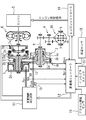
図1はVベルト式無段変速機の構成の概略を示すものである。
プライマリプーリ2およびセカンダリプーリ3が、両者のV溝が整列するように配置され、これらプーリ2、3のV溝にVベルト4が掛け渡されている。駆動源であるエンジン5をプライマリプーリ2と同軸に配置し、このエンジン5とプライマリプーリ2との間に、エンジン5から順次ロックアップ機構を有するトルクコンバータ6および前後進切り替え機構7を設ける。トルクコンバータ6、前後進切り替え機構7、プライマリプーリ2、セカンダリプーリ3およびVベルト4よりVベルト式無段変速機1が構成される。
Next, embodiments of the present invention will be described by way of examples.
FIG. 1 schematically shows the configuration of a V-belt type continuously variable transmission.
The primary pulley 2 and the secondary pulley 3 are arranged so that their V grooves are aligned, and the V belt 4 is stretched over the V grooves of these pulleys 2 and 3. An
前後進切り替え機構7は、ダブルピニオン遊星歯車組7aを主たる構成要素とし、そのサンギヤをトルクコンバータ6を介してエンジン5に結合し、キャリアをプライマリプーリ2に結合する。前後進切り替え機構7は更に、ダブルピニオン遊星歯車組7aのサンギヤおよびキャリア間を直結する前進クラッチ7b、およびリングギヤを固定する後進ブレーキ7cを備え、前進クラッチ7bの締結時にエンジン5からトルクコンバータ6を経由した入力回転をそのままプライマリプーリ2に伝達する。また後進ブレーキ7cの締結時には、エンジン5からトルクコンバータ6を経由した入力回転を逆転減速してプライマリプーリ2へ伝達する。
The forward / reverse switching mechanism 7 includes a double pinion planetary gear set 7 a as a main component, and the sun gear is coupled to the
プライマリプーリ2の回転はVベルト4を介してセカンダリプーリ3に伝達され、セカンダリプーリ3の回転はその後、出力軸8、歯車組9およびディフアレンシヤルギヤ10を経て図示しない車輪へ伝達される。
上記の動力伝達中にプライマリプーリ2とセカンダリプーリ3との間における回転伝動比(変速比)を変更可能にするために、プライマリプーリ2およびセカンダリプーリ3のV溝を形成するフランジのうち一方を固定フランジ2a、3aとし、他方のフランジ2b、3bを軸線方向へ変位可能な可動フランジとする。これら可動フランジ2b、3bはそれぞれ、詳しくは後述するライン圧を基圧として作り出したプライマリプーリ圧Ppri、およびセカンダリプーリ圧Psecをプライマリプーリ室2cおよびセカンダリプーリ室3cに供給することにより固定フランジ2a、3a側に付勢され、Vベルト4を固定フランジ2aと可動フランジ2b間、および固定フランジ3aと可動フランジ3b間に摩擦係合させて、プライマリプーリ2とセカンダリプーリ3との間での前記動力伝達を可能にする。
The rotation of the primary pulley 2 is transmitted to the secondary pulley 3 via the V-belt 4, and the rotation of the secondary pulley 3 is then transmitted to a wheel (not shown) via the
In order to be able to change the rotational transmission ratio (transmission ratio) between the primary pulley 2 and the secondary pulley 3 during the power transmission described above, one of the flanges forming the V-grooves of the primary pulley 2 and the secondary pulley 3 is The fixed flanges 2a and 3a are used, and the
なお本実施例においては特に、プライマリプーリ室2cおよびセカンダリプーリ室3cの受圧面積を同じにし、プーリ2、3の一方が大径になることのないようにし、これによりVベルト式無段変速機の小型化を図る。
また変速に際しては、後述のごとく目標変速比に対応させて発生させたプライマリプーリ圧Ppriおよびセカンダリプーリ圧Psec間の差圧により、両プーリ2、3のV溝幅を変更して、これらプーリ2、3に対するVベルト4の巻き掛け円弧径を連続的に変化させることで目標変速比を実現することができる。
In the present embodiment, in particular, the pressure receiving areas of the
Further, when shifting, the V groove widths of both pulleys 2 and 3 are changed by the differential pressure between the primary pulley pressure Ppri and the secondary pulley pressure Psec generated corresponding to the target gear ratio, as will be described later. 3, the target transmission gear ratio can be realized by continuously changing the winding arc diameter of the V belt 4 with respect to 3.
プライマリプーリ圧Ppriおよびセカンダリプーリ圧Psecの出力は、前進走行レンジの選択時に締結すべき前進クラッチ7bおよび後進走行レンジの選択時に締結すべき後進ブレーキ7cの締結油圧の出力と共に変速制御油圧回路11により制御し、この変速制御油圧回路11は変速機コントローラ12からの信号に応答して当該制御を行うものとする。
The outputs of the primary pulley pressure Ppri and the secondary pulley pressure Psec are output by the shift control
このため変速機コントローラ12には、プライマリプーリ回転数Npriを検出するプライマリプーリ回転センサ13からの信号と、セカンダリプーリ回転数Nsecを検出するセカンダリプーリ回転センサ14からの信号と、セカンダリプーリ圧Psecを検出するセカンダリプーリ圧センサ15からの信号と、アクセルペダル踏み込み量APOを検出するアクセル開度センサ16からの信号と、インヒビタスイッチ17からの選択レンジ信号と、変速作動油温TMPを検出する油温センサ18からの信号と、エンジン5の制御を行うエンジンコントローラ19からのエンジントルク情報に関連する信号(エンジン回転数や燃料噴射時間、エンジンの出力トルク情報など)とが入力される。
さらに変速機コントローラ12には、プライマリプーリ圧Ppriを検出するプライマリプーリ圧センサ30からの信号が入力されている。
For this reason, the
Further, the
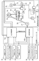
次に図2を用いて、変速制御油圧回路11および変速機コントローラ12で行われる制御について説明する。
変速制御油圧回路11は、エンジン駆動されるオイルポンプ21を備え、これから油路22への作動油を媒体として、これをプレッシャレギュレータ弁(P.Reg弁)23により所定のライン圧PLに調圧する。油路22のライン圧PLは、一方で減圧弁24により調圧されセカンダリプーリ圧Psecとしてセカンダリプーリ室(SEC)3cに供給され、他方で変速制御弁25により調圧されプライマリプーリ圧Ppriとしてプライマリプーリ室(PRI)2cに供給される。なお、プレッシャレギュレータ弁23は、ソレノイド23aへの駆動デューティーによりライン圧PLを制御し、減圧弁24は、ソレノイド24aへの駆動デューティーによりセカンダリプーリ圧Psecを制御するものとする。
Next, the control performed by the shift control
The shift control
変速制御弁25は、中立位置25aと、増圧位置25bと、減圧位置25cとを有し、これら弁位置を切り換えるために変速制御弁25を変速リンク26の中程に連結し、該変速リンク26の一端に、変速アクチュエータとしてのステップモータ(M)27を、また他端にプライマリプーリの可動フランジ2bを連結する。ステップモータ27は、基準位置から目標変速比に対応したステップ数だけ進んだ作動位置に駆動され、かかるステップモータ27の駆動により変速リンク26が可動フランジ2bとの連結部を支点にして揺動することにより、変速制御弁25を中立位置25aから増圧位置25bまたは減圧位置25cに変化させる。
The speed
その結果、目標変速比が高速側(アップシフト側)である場合にはライン圧PLがプライマリプーリ圧Ppri側と連通し、一方低速側(ダウンシフト側)である場合にはプライマリプーリ圧Ppriがドレン側と連通することとなる。これにより、プライマリプーリ圧Ppriがライン圧PLを基圧として増圧、またはドレンにより減圧され、セカンダリプーリ圧Psecとの差圧が変化することでHi側変速比へのアップシフトまたはLo側変速比へのダウンシフトを生じ、目標変速比に向けての変速動作が行われる。 As a result, when the target gear ratio is on the high speed side (upshift side), the line pressure PL communicates with the primary pulley pressure Ppri side. On the other hand, when the target gear ratio is on the low speed side (downshift side), the primary pulley pressure Ppri is It will communicate with the drain side. As a result, the primary pulley pressure Ppri is increased with the line pressure PL as the base pressure, or is reduced by the drain, and the differential pressure with the secondary pulley pressure Psec is changed so that the upshift to the Hi-side gear ratio or the Lo-side gear ratio. Downshift to the target gear ratio is performed.
当該変速の進行は、プライマリプーリの可動フランジ2bを介して変速リンク26にフイードバックされ、変速リンク26がステップモータ27との連結部を支点にして、変速制御弁25を増圧位置25bまたは減圧位置25cから中立位置25aに戻す方向へ揺動する。これにより、目標変速比が達成される時に変速制御弁25が中立位置25aに戻され、目標変速比を保つことができる。なお、プーリが最Lo位置にある場合には、プライマリプーリ圧Ppriの有無にかかわらず、図示しない機械的なストッパがプーリに反力を与えることとしているため、Vベルト4の伝達トルクの容量は確保されることとなっている。
The speed change is fed back to the
プレッシャレギュレータ弁23のソレノイド駆動デューティー、減圧弁24のソレノイド駆動デューティー、およびステップモータ27への変速指令(ステップ数)は、図1に示す前進クラッチ7bおよび後進ブレーキ7cへ締結油圧を供給するか否かの制御と共に変速機コントローラ12により決定し、このコントローラ12を図2に示すように圧力制御部12aおよび変速制御部12bで構成する。圧力制御部12aは、プレッシャレギュレータ弁23のソレノイド駆動デューティー、および減圧弁24のソレノイド駆動デューティーを決定し、変速制御部12bは以下のようにしてステップモータ27の駆動ステップ数Astepを決定する。
The solenoid drive duty of the
変速制御部12bは先ず、セカンダリプーリ回転数Nsecから求め得る車速およびアクセルペダル踏み込み量APOを用いて予定の変速マップを基に目標入力回転数を求め、これをセカンダリプーリ回転数Nsecで除算することにより、運転状態(車速およびアクセルペダル踏み込み量APO)に応じた目標変速比を求める。
First, the speed
次いで、プライマリプーリ回転数Npriをセカンダリプーリ回転数Nsecで除算することにより実変速比(到達変速比)を演算し、上記目標変速比に対する実変速比の偏差に応じて外乱補償しながら実変速比を目標変速速度で目標変速比に漸近させるための変速比指令を求める。そして、この変速比指令を実現するためのステップモータ27のステップ数(ステップモータ27の作動位置)Astepを求め、これをステップモータ27に指令することで前記の変速動作により目標変速比を達成することができる。
Next, the actual speed ratio (reached speed ratio) is calculated by dividing the primary pulley speed Npri by the secondary pulley speed Nsec, and the actual speed ratio is compensated for disturbance according to the deviation of the actual speed ratio with respect to the target speed ratio. A speed ratio command for asymptotically approaching the target speed ratio at the target speed is obtained. Then, the step number of the step motor 27 (operation position of the step motor 27) Astep for realizing the gear ratio command is obtained, and this is commanded to the
次に、変速比の異常上昇時に変速機コントローラ12が行う処理について説明する。
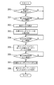
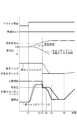
図3は、変速機コントローラ12が行う処理の流れを示すフローチャートであり、図4は、本制御における各部の動作を示すタイムチャートである。
本処理は、イグニッションスイッチがオンとなったときに開始される。
イグニッションスイッチがオンとなった後、図4に示すように時刻t1において運転者によってアクセルが踏まれて、図4に破線で示す実セカンダリプーリ圧が上昇を始める。
Next, a process performed by the
FIG. 3 is a flowchart showing the flow of processing performed by the
This process is started when the ignition switch is turned on.
After the ignition switch is turned on, the accelerator is stepped on by the driver at time t1 as shown in FIG. 4, and the actual secondary pulley pressure indicated by the broken line in FIG. 4 starts to rise.
エンジンからの動力が伝達されて、プライマリプーリ2が回転を始めると、セカンダリプーリ回転センサ14が故障している場合およびVベルト4に滑りが発生している場合には、プライマリプーリ回転センサ13によるプライマリプーリ2の回転数の検出のみが行われる。
これによりプライマリプーリ回転センサ13によって検出された回転数を、セカンダリプーリ回転センサ14によって検出された回転数で除算することによって得られる変速比が、図4に実線で示すように時刻t1以降において異常上昇(低速(Low)側へ変化)する。
なお、セカンダリプーリ回転センサ14が正常であり、Vベルトに滑りが発生していない場合には、図4に破線で示すように変速比が減少(高速(Hi)側へ変化)する。
When the power from the engine is transmitted and the primary pulley 2 starts to rotate, when the secondary
As a result, the speed ratio obtained by dividing the rotational speed detected by the primary pulley
When the secondary
ステップ300において変速機コントローラ12は、プライマリプーリ回転センサ13およびセカンダリプーリ回転センサ14による検出結果より算出される変速比が、所定変速比以上となったかどうかの判断を行う。
変速比が異常上昇して所定変速比以上となった場合(図4における時刻t2)には、セカンダリプーリ回転センサ14の故障、またはVベルトに滑りが発生しているとしてステップ301へ進む。
一方、変速比が所定変速比以上となっていない場合には、ステップ300における処理を繰り返す。
In
If the gear ratio increases abnormally and exceeds the predetermined gear ratio (time t2 in FIG. 4), the process proceeds to step 301 on the assumption that the secondary
On the other hand, if the gear ratio is not greater than or equal to the predetermined gear ratio, the process in
ステップ301において、変速比所定値以上の状態が第1の所定時間以上継続されたかどうかの判断を行い、第1の所定時間以上継続された場合(図4における時刻t3)にはステップ302へ進み、第1の所定時間以上継続されなかった場合にはステップ300へ戻り上述の処理を繰り返す。
In
ステップ302において変速機コントローラ12は、図4に示す時刻t3においてエンジンコントローラ19に対して指示するエンジンの要求トルク(図4に実線で図示)を所定要求トルクまで急減少させる。
なおエンジンの実エンジントルクは、時刻t3以降図4に破線で示すように減少する。
ステップ303において変速機コントローラ12は、図4に示す時刻t3においてセカンダリプーリ圧の上限規制値を所定圧まで減少させる。
これにより時刻t3において、セカンダリプーリ圧の上限規制に追従して図4に実線で示すように目標セカンダリプーリ圧が所定圧まで減少する。
なお、セカンダリプーリ圧の上限規制値は、時刻t3から所定時間経過後に所定勾配で後述の破損限界圧となるまで減少させる。
In
The actual engine torque of the engine decreases after time t3 as indicated by a broken line in FIG.
In
Thus, at time t3, the target secondary pulley pressure is reduced to a predetermined pressure as shown by the solid line in FIG. 4 following the upper limit restriction of the secondary pulley pressure.
Note that the upper limit regulation value of the secondary pulley pressure is decreased at a predetermined gradient until a later-described failure limit pressure is reached after a predetermined time has elapsed from time t3.
ステップ304において変速機コントローラ12は、目標セカンダリプーリ圧の上限を所定圧に規制してから(時刻t3から)第2の所定時間以上経過したかどうかを判断する。
第2の所定時間を経過した場合にはステップ305へ進み、経過していない場合にはステップ304における処理を繰り返す。
In
If the second predetermined time has elapsed, the process proceeds to step 305. If not, the process in
目標セカンダリプーリの上限が所定圧に規制されてから第2の所定時間が経過した時刻t4において、ステップ305で変速機コントローラ12は、実エンジントルクに応じたセカンダリプーリ圧制御を行う。
これは、エンジンコントローラ19から変速機コントローラ12へ入力されるエンジントルク関連情報より得られるエンジントルクにもとづいて、目標セカンダリプーリ圧の制御を行うものである。
At time t4 when the second predetermined time has elapsed since the upper limit of the target secondary pulley was regulated to the predetermined pressure, in
This is to control the target secondary pulley pressure based on the engine torque obtained from the engine torque related information input from the
これにより図4に示すように時刻t4以降において、目標セカンダリプーリ圧が減少し、これに追従する実セカンダリプーリ圧が減少する。
また目標セカンダリプーリ圧は、時刻t3の時点において実際にVベルト4に滑りが発生していた場合に、ベルトに滑りを発生させることなく再把持可能な限界圧まで減少させるものとする。目標セカンダリプーリ圧が限界圧となった後は、限界圧を後述の時刻t6まで維持する。
なお前述の所定要求トルクは、限界圧によってVベルトを把持する場合にVベルトに滑りを発生させることのない値とする。
これによって実際にVベルト4に滑りが発生している場合には、Vベルトに滑りを発生させることなく再把持を行うことができる。
As a result, as shown in FIG. 4, the target secondary pulley pressure decreases after time t4, and the actual secondary pulley pressure following this decreases.
Further, the target secondary pulley pressure is reduced to a limit pressure that can be re-gripped without causing the belt to slip when slippage has actually occurred at the time t3. After the target secondary pulley pressure reaches the limit pressure, the limit pressure is maintained until time t6 described later.
The above-mentioned predetermined required torque is a value that does not cause the V belt to slip when the V belt is gripped by the limit pressure.
As a result, when slippage has actually occurred in the V-belt 4, re-gripping can be performed without causing slippage in the V-belt.
ステップ306において変速機コントローラ12は、セカンダリプーリ圧の上限を所定圧に規制した時刻t3から、第3の所定時間が経過したかどうかを判断し、第3の所定時間が経過している場合には、ステップ307へ進み、経過していない場合には本ステップの処理を繰り返す。
時刻t3から第3の所定時間が経過した時刻t6において、ステップ307で変速機コントローラ12は、セカンダリプーリ圧の上限規制値を所定勾配で上昇させることによって、目標セカンダリプーリ圧を徐々に上昇させる。
ステップ308において変速機コントローラ12は、エンジンコントローラ19に対して実セカンダリプーリ圧に応じたエンジンの要求トルク指示を行う。
In
At time t6 when the third predetermined time has elapsed from time t3, in step 307, the
In
本実施例は以上のように構成され、セカンダリプーリ回転センサ14の故障またはVベルト4の滑りによって変速比が異常上昇した場合に、エンジンの要求トルクを急減少させ、目標セカンダリプーリ圧の上限規制を第2の所定時間行った後、エンジンの出力トルクに応じた目標セカンダリプーリ圧の制御を行う。
これにより、セカンダリプーリ回転センサ14が故障していた場合に、実際に発生しているセカンダリプーリ圧によってVベルトを把持可能なベルト容量をエンジンの実トルクが超えてしまうことがないので、Vベルトに滑りが発生することがない。
The present embodiment is configured as described above, and when the gear ratio is abnormally increased due to a failure of the secondary
Thereby, when the secondary
なお、本実施例において、プライマリプーリ2の回転数をプライマリプーリ回転センサ13を用いて検出するものとしたが、たとえばトルクコンバータ6の出力軸の回転数より検出することもできる。
同様にセカンダリプーリ3の回転数についても、セカンダリプーリ回転センサ14以外によって検出することもできる。
これにより、たとえばプライマリプーリの回転数をプライマリプーリ回転センサ13でなく、トルクコンバータ6の出力軸回転数より検出しているベルト式無段変速機においても、プライマリプーリ回転センサを追加することなく、上記油圧制御を行うことができる。
In the present embodiment, the rotation speed of the primary pulley 2 is detected using the primary
Similarly, the rotational speed of the secondary pulley 3 can also be detected by other than the secondary
Thereby, for example, in the belt-type continuously variable transmission that detects the rotation speed of the primary pulley not from the primary
1 Vベルト式無段変速機
2 プライマリプーリ
3 セカンダリプーリ
4 Vベルト (ベルト)
5 エンジン
6 トルクコンバータ
7 前後進切り替え機構
11 変速制御油圧回路
12 変速機コントローラ
13 プライマリプーリ回転センサ (プライマリプーリ側回転数検出部)
14 セカンダリプーリ回転センサ (セカンダリプーリ側回転数検出部)
15 セカンダリプーリ圧センサ
16 アクセル開度センサ
17 インヒビタスイッチ
18 油温センサ
19 エンジンコントローラ
21 オイルポンプ
23 プレッシャレギュレータ弁
24 減圧弁
25 変速制御弁
26 変速リンク
27 ステップモータ
30 プライマリプーリ圧センサ
1 V-belt type continuously variable transmission 2 Primary pulley 3 Secondary pulley 4 V-belt (belt)
DESCRIPTION OF
14 Secondary pulley rotation sensor (Secondary pulley side rotation speed detector)
DESCRIPTION OF
Claims (3)
前記プライマリプーリの回転数を検出するプライマリプーリ側回転数検出部、およびセカンダリプーリの回転数を検出するセカンダリプーリ側回転数検出部より得られる両プーリの実変速比が目標変速比となるように、変速機コントローラが、前記プライマリプーリに作用させるプライマリプーリ圧の目標値となる目標プライマリプーリ圧、および前記セカンダリプーリに作用させるセカンダリプーリ圧の目標値となる目標セカンダリプーリ圧の算出を行う車両用ベルト式無段変速機の油圧制御装置において、
前記実変速比が所定変速比以上上昇した場合に、前記変速機コントローラは、
前記エンジンコントローラに対して前記エンジンの出力トルクの減少を指示し、
前記目標セカンダリプーリ圧を、前記エンジンの出力トルク減少指示から所定時間の経過後、前記エンジンの出力トルクに応じた前記目標セカンダリプーリ圧に制御することを特徴とする車両用ベルト式無段変速機の油圧制御装置。 A belt is stretched between the primary pulley to which power from the engine controlled by the engine controller is input and the secondary pulley on the output side,
The actual gear ratio of both pulleys obtained from the primary pulley-side rotation speed detection unit that detects the rotation speed of the primary pulley and the secondary pulley-side rotation speed detection unit that detects the rotation speed of the secondary pulley is the target gear ratio. And a transmission controller that calculates a target primary pulley pressure that is a target value of a primary pulley pressure that is applied to the primary pulley and a target secondary pulley pressure that is a target value of a secondary pulley pressure that is applied to the secondary pulley. In the hydraulic control device of a belt type continuously variable transmission,
When the actual gear ratio increases by a predetermined gear ratio or more, the transmission controller
Instructing the engine controller to reduce the output torque of the engine,
A belt type continuously variable transmission for a vehicle, wherein the target secondary pulley pressure is controlled to the target secondary pulley pressure corresponding to the output torque of the engine after a lapse of a predetermined time from an instruction to reduce the output torque of the engine. Hydraulic control device.
前記目標セカンダリプーリ圧の上限を規制することによってセカンダリプーリ圧を制限することを特徴とする請求項1記載の車両用ベルト式無段変速機の油圧制御装置。 While the predetermined time elapses, the transmission controller
2. The hydraulic control device for a belt-type continuously variable transmission for a vehicle according to claim 1, wherein the secondary pulley pressure is limited by regulating an upper limit of the target secondary pulley pressure.
または、前記セカンダリプーリ側回転数検出部は、前記セカンダリプーリの回転数を直接検出するセカンダリプーリ回転センサが用いられることを特徴とする請求項1または2記載の車両用ベルト式無段変速機の油圧制御装置。 The primary pulley side rotation speed detection unit uses a primary pulley rotation sensor that directly detects the rotation speed of the primary pulley,
3. The belt type continuously variable transmission for a vehicle according to claim 1 or 2, wherein the secondary pulley side rotation speed detection unit uses a secondary pulley rotation sensor that directly detects the rotation speed of the secondary pulley. Hydraulic control device.
Priority Applications (3)
| Application Number | Priority Date | Filing Date | Title |
|---|---|---|---|
| JP2004108199A JP2005291395A (en) | 2004-03-31 | 2004-03-31 | Hydraulic control device for belt type continuously variable transmission for vehicle |
| EP05251445A EP1582779A3 (en) | 2004-03-31 | 2005-03-10 | Hydraulic control system of belt-type continuously variable transmission for vehicle |
| US11/092,537 US7510501B2 (en) | 2004-03-31 | 2005-03-29 | Hydraulic control system of belt-type continuously variable transmission for vehicle |
Applications Claiming Priority (1)
| Application Number | Priority Date | Filing Date | Title |
|---|---|---|---|
| JP2004108199A JP2005291395A (en) | 2004-03-31 | 2004-03-31 | Hydraulic control device for belt type continuously variable transmission for vehicle |
Publications (1)
| Publication Number | Publication Date |
|---|---|
| JP2005291395A true JP2005291395A (en) | 2005-10-20 |
Family
ID=34880111
Family Applications (1)
| Application Number | Title | Priority Date | Filing Date |
|---|---|---|---|
| JP2004108199A Pending JP2005291395A (en) | 2004-03-31 | 2004-03-31 | Hydraulic control device for belt type continuously variable transmission for vehicle |
Country Status (3)
| Country | Link |
|---|---|
| US (1) | US7510501B2 (en) |
| EP (1) | EP1582779A3 (en) |
| JP (1) | JP2005291395A (en) |
Cited By (4)
| Publication number | Priority date | Publication date | Assignee | Title |
|---|---|---|---|---|
| JP2010510448A (en) * | 2006-11-17 | 2010-04-02 | ツェットエフ、フリードリッヒスハーフェン、アクチエンゲゼルシャフト | Method for emergency operation of an automatic automobile double clutch transmission |
| JP2011194978A (en) * | 2010-03-18 | 2011-10-06 | Toyota Motor Corp | Power train control apparatus |
| JPWO2014157183A1 (en) * | 2013-03-25 | 2017-02-16 | ジヤトコ株式会社 | Abnormality detection device and abnormality detection method for hybrid vehicle |
| JP2020085025A (en) * | 2018-11-16 | 2020-06-04 | 本田技研工業株式会社 | Vehicle control device, vehicle, and vehicle control method |
Families Citing this family (6)
| Publication number | Priority date | Publication date | Assignee | Title |
|---|---|---|---|---|
| JP4051361B2 (en) * | 2004-08-06 | 2008-02-20 | ジヤトコ株式会社 | Arrangement structure of continuously variable transmission and manufacturing method thereof |
| US9441733B2 (en) * | 2012-06-08 | 2016-09-13 | Jatco Ltd | Continuously variable transmission and a hydraulic control method thereof |
| US9151382B2 (en) * | 2014-02-24 | 2015-10-06 | GM Global Technology Operations LLC | Gross slip-based control of a variator assembly |
| JP6493050B2 (en) * | 2015-07-16 | 2019-04-03 | トヨタ自動車株式会社 | Hydraulic control device for continuously variable transmission for vehicle |
| WO2022153688A1 (en) * | 2021-01-14 | 2022-07-21 | ジヤトコ株式会社 | Transmission, method for controlling transmission, and program |
| JP7241124B2 (en) * | 2021-04-21 | 2023-03-16 | 本田技研工業株式会社 | Control device and control method for continuously variable transmission for vehicle |
Family Cites Families (18)
| Publication number | Priority date | Publication date | Assignee | Title |
|---|---|---|---|---|
| JPS62143744A (en) * | 1985-12-19 | 1987-06-27 | Fuji Heavy Ind Ltd | Transmission gear ratio control of continuously variable transmission for vehicle |
| DE19650218A1 (en) * | 1996-12-04 | 1998-06-10 | Zahnradfabrik Friedrichshafen | Method for controlling a CVT |
| DE19712451A1 (en) * | 1997-03-25 | 1998-10-01 | Bosch Gmbh Robert | Device and method for controlling a CVT in a motor vehicle |
| DE19712713A1 (en) * | 1997-03-26 | 1998-10-01 | Bosch Gmbh Robert | Device and method for controlling a CVT in a motor vehicle |
| DE19858263A1 (en) | 1998-12-17 | 2000-06-21 | Zahnradfabrik Friedrichshafen | Method for monitoring a continuously variable transmission |
| JP4009053B2 (en) * | 2000-04-26 | 2007-11-14 | 三菱自動車工業株式会社 | Line pressure control device for belt type continuously variable transmission |
| JP2001330135A (en) | 2000-05-23 | 2001-11-30 | Toyota Motor Corp | Control device for belt type continuously variable transmission |
| DE10111830A1 (en) | 2001-03-13 | 2002-09-26 | Zahnradfabrik Friedrichshafen | Controlling drive train with continuous automatic gearbox involves interrupting force connection before emergency operation is established if electronic control unit fails |
| JP2004068686A (en) * | 2002-08-05 | 2004-03-04 | Jatco Ltd | Engine torque control device |
| JP3993489B2 (en) * | 2002-08-26 | 2007-10-17 | ジヤトコ株式会社 | Belt slip prevention device for belt type continuously variable transmission |
| JP4291555B2 (en) * | 2002-09-20 | 2009-07-08 | ジヤトコ株式会社 | Shift control device for continuously variable transmission |
| JP4107484B2 (en) * | 2002-09-27 | 2008-06-25 | ジヤトコ株式会社 | Shift control device for V-belt continuously variable automatic transmission |
| JP2004124965A (en) * | 2002-09-30 | 2004-04-22 | Jatco Ltd | Control device for belt-type continuously variable transmission |
| JP3981317B2 (en) * | 2002-10-04 | 2007-09-26 | ジヤトコ株式会社 | Hydraulic pressure drop detecting device for vehicle transmission |
| JP3898654B2 (en) * | 2003-02-27 | 2007-03-28 | ジヤトコ株式会社 | Engine torque control device |
| JP2004316843A (en) * | 2003-04-18 | 2004-11-11 | Jatco Ltd | Control device for belt-type continuously variable transmission |
| JP4084777B2 (en) * | 2004-03-31 | 2008-04-30 | ジヤトコ株式会社 | Input torque control device for belt type continuously variable transmission for vehicle |
| JP2005291111A (en) * | 2004-03-31 | 2005-10-20 | Jatco Ltd | Input torque control device for belt type continuously variable transmission for vehicle |
-
2004
- 2004-03-31 JP JP2004108199A patent/JP2005291395A/en active Pending
-
2005
- 2005-03-10 EP EP05251445A patent/EP1582779A3/en not_active Withdrawn
- 2005-03-29 US US11/092,537 patent/US7510501B2/en not_active Expired - Fee Related
Cited By (5)
| Publication number | Priority date | Publication date | Assignee | Title |
|---|---|---|---|---|
| JP2010510448A (en) * | 2006-11-17 | 2010-04-02 | ツェットエフ、フリードリッヒスハーフェン、アクチエンゲゼルシャフト | Method for emergency operation of an automatic automobile double clutch transmission |
| JP2011194978A (en) * | 2010-03-18 | 2011-10-06 | Toyota Motor Corp | Power train control apparatus |
| JPWO2014157183A1 (en) * | 2013-03-25 | 2017-02-16 | ジヤトコ株式会社 | Abnormality detection device and abnormality detection method for hybrid vehicle |
| JP2020085025A (en) * | 2018-11-16 | 2020-06-04 | 本田技研工業株式会社 | Vehicle control device, vehicle, and vehicle control method |
| US10883597B2 (en) | 2018-11-16 | 2021-01-05 | Honda Motor Co., Ltd. | Vehicle control device, vehicle, and vehicle control method |
Also Published As
| Publication number | Publication date |
|---|---|
| EP1582779A3 (en) | 2007-07-11 |
| US7510501B2 (en) | 2009-03-31 |
| EP1582779A2 (en) | 2005-10-05 |
| US20050221930A1 (en) | 2005-10-06 |
Similar Documents
| Publication | Publication Date | Title |
|---|---|---|
| KR101362103B1 (en) | Control device for continuously variable transmission | |
| JP4047122B2 (en) | Anti-slip device for V-belt type continuously variable transmission | |
| JP4613225B2 (en) | Control device for continuously variable transmission | |
| JP4291555B2 (en) | Shift control device for continuously variable transmission | |
| JP4414972B2 (en) | Vehicle control device | |
| JP4762875B2 (en) | Shift control device for belt type continuously variable transmission | |
| JP4344379B2 (en) | Control device for continuously variable transmission | |
| JP4084777B2 (en) | Input torque control device for belt type continuously variable transmission for vehicle | |
| US7179196B2 (en) | Input torque control system of belt-type continuously variable transmission for vehicle | |
| KR100481567B1 (en) | Control device of driver with non-stage transmission mechanism | |
| JP4183670B2 (en) | Shift control device for continuously variable transmission | |
| JP4071649B2 (en) | Shift control device for belt type continuously variable transmission | |
| JP3898654B2 (en) | Engine torque control device | |
| JP2005291395A (en) | Hydraulic control device for belt type continuously variable transmission for vehicle | |
| KR101939527B1 (en) | Control device of transmission and control method of transmission | |
| JP2004116606A (en) | Control device for belt-type continuously variable transmission system for vehicles | |
| JP4152709B2 (en) | Shift control device for V-belt type continuously variable transmission | |
| JP2008106813A (en) | Hydraulic control device for belt type continuously variable transmission for vehicle | |
| US10605358B2 (en) | Transmission and control method for transmission | |
| JP6379280B2 (en) | Transmission control device and transmission control method |
Legal Events
| Date | Code | Title | Description |
|---|---|---|---|
| A621 | Written request for application examination |
Free format text: JAPANESE INTERMEDIATE CODE: A621 Effective date: 20050818 |
|
| A977 | Report on retrieval |
Free format text: JAPANESE INTERMEDIATE CODE: A971007 Effective date: 20071024 |
|
| A131 | Notification of reasons for refusal |
Free format text: JAPANESE INTERMEDIATE CODE: A131 Effective date: 20080108 |
|
| A521 | Written amendment |
Free format text: JAPANESE INTERMEDIATE CODE: A523 Effective date: 20080303 |
|
| A131 | Notification of reasons for refusal |
Free format text: JAPANESE INTERMEDIATE CODE: A131 Effective date: 20080408 |
|
| A521 | Written amendment |
Free format text: JAPANESE INTERMEDIATE CODE: A523 Effective date: 20080417 |
|
| A131 | Notification of reasons for refusal |
Free format text: JAPANESE INTERMEDIATE CODE: A131 Effective date: 20080826 |
|
| A521 | Written amendment |
Free format text: JAPANESE INTERMEDIATE CODE: A523 Effective date: 20081024 |
|
| A02 | Decision of refusal |
Free format text: JAPANESE INTERMEDIATE CODE: A02 Effective date: 20090616 |