JP2005291111A - Input torque control device for belt type continuously variable transmission for vehicle - Google Patents
Input torque control device for belt type continuously variable transmission for vehicle Download PDFInfo
- Publication number
- JP2005291111A JP2005291111A JP2004108200A JP2004108200A JP2005291111A JP 2005291111 A JP2005291111 A JP 2005291111A JP 2004108200 A JP2004108200 A JP 2004108200A JP 2004108200 A JP2004108200 A JP 2004108200A JP 2005291111 A JP2005291111 A JP 2005291111A
- Authority
- JP
- Japan
- Prior art keywords
- secondary pulley
- input torque
- vehicle
- pulley
- primary pulley
- Prior art date
- Legal status (The legal status is an assumption and is not a legal conclusion. Google has not performed a legal analysis and makes no representation as to the accuracy of the status listed.)
- Pending
Links
Images
Classifications
-
- F—MECHANICAL ENGINEERING; LIGHTING; HEATING; WEAPONS; BLASTING
- F16—ENGINEERING ELEMENTS AND UNITS; GENERAL MEASURES FOR PRODUCING AND MAINTAINING EFFECTIVE FUNCTIONING OF MACHINES OR INSTALLATIONS; THERMAL INSULATION IN GENERAL
- F16H—GEARING
- F16H61/00—Control functions within control units of change-speed- or reversing-gearings for conveying rotary motion ; Control of exclusively fluid gearing, friction gearing, gearings with endless flexible members or other particular types of gearing
- F16H61/66—Control functions within control units of change-speed- or reversing-gearings for conveying rotary motion ; Control of exclusively fluid gearing, friction gearing, gearings with endless flexible members or other particular types of gearing specially adapted for continuously variable gearings
- F16H61/662—Control functions within control units of change-speed- or reversing-gearings for conveying rotary motion ; Control of exclusively fluid gearing, friction gearing, gearings with endless flexible members or other particular types of gearing specially adapted for continuously variable gearings with endless flexible members
- F16H61/66272—Control functions within control units of change-speed- or reversing-gearings for conveying rotary motion ; Control of exclusively fluid gearing, friction gearing, gearings with endless flexible members or other particular types of gearing specially adapted for continuously variable gearings with endless flexible members characterised by means for controlling the torque transmitting capability of the gearing
-
- B—PERFORMING OPERATIONS; TRANSPORTING
- B60—VEHICLES IN GENERAL
- B60W—CONJOINT CONTROL OF VEHICLE SUB-UNITS OF DIFFERENT TYPE OR DIFFERENT FUNCTION; CONTROL SYSTEMS SPECIALLY ADAPTED FOR HYBRID VEHICLES; ROAD VEHICLE DRIVE CONTROL SYSTEMS FOR PURPOSES NOT RELATED TO THE CONTROL OF A PARTICULAR SUB-UNIT
- B60W10/00—Conjoint control of vehicle sub-units of different type or different function
- B60W10/04—Conjoint control of vehicle sub-units of different type or different function including control of propulsion units
- B60W10/06—Conjoint control of vehicle sub-units of different type or different function including control of propulsion units including control of combustion engines
-
- B—PERFORMING OPERATIONS; TRANSPORTING
- B60—VEHICLES IN GENERAL
- B60W—CONJOINT CONTROL OF VEHICLE SUB-UNITS OF DIFFERENT TYPE OR DIFFERENT FUNCTION; CONTROL SYSTEMS SPECIALLY ADAPTED FOR HYBRID VEHICLES; ROAD VEHICLE DRIVE CONTROL SYSTEMS FOR PURPOSES NOT RELATED TO THE CONTROL OF A PARTICULAR SUB-UNIT
- B60W10/00—Conjoint control of vehicle sub-units of different type or different function
- B60W10/10—Conjoint control of vehicle sub-units of different type or different function including control of change-speed gearings
- B60W10/101—Infinitely variable gearings
- B60W10/107—Infinitely variable gearings with endless flexible members
-
- F—MECHANICAL ENGINEERING; LIGHTING; HEATING; WEAPONS; BLASTING
- F16—ENGINEERING ELEMENTS AND UNITS; GENERAL MEASURES FOR PRODUCING AND MAINTAINING EFFECTIVE FUNCTIONING OF MACHINES OR INSTALLATIONS; THERMAL INSULATION IN GENERAL
- F16H—GEARING
- F16H61/00—Control functions within control units of change-speed- or reversing-gearings for conveying rotary motion ; Control of exclusively fluid gearing, friction gearing, gearings with endless flexible members or other particular types of gearing
- F16H61/12—Detecting malfunction or potential malfunction, e.g. fail safe ; Circumventing or fixing failures
- F16H2061/1208—Detecting malfunction or potential malfunction, e.g. fail safe ; Circumventing or fixing failures with diagnostic check cycles; Monitoring of failures
-
- F—MECHANICAL ENGINEERING; LIGHTING; HEATING; WEAPONS; BLASTING
- F16—ENGINEERING ELEMENTS AND UNITS; GENERAL MEASURES FOR PRODUCING AND MAINTAINING EFFECTIVE FUNCTIONING OF MACHINES OR INSTALLATIONS; THERMAL INSULATION IN GENERAL
- F16H—GEARING
- F16H61/00—Control functions within control units of change-speed- or reversing-gearings for conveying rotary motion ; Control of exclusively fluid gearing, friction gearing, gearings with endless flexible members or other particular types of gearing
- F16H61/12—Detecting malfunction or potential malfunction, e.g. fail safe ; Circumventing or fixing failures
- F16H2061/122—Avoiding failures by using redundant parts
-
- F—MECHANICAL ENGINEERING; LIGHTING; HEATING; WEAPONS; BLASTING
- F16—ENGINEERING ELEMENTS AND UNITS; GENERAL MEASURES FOR PRODUCING AND MAINTAINING EFFECTIVE FUNCTIONING OF MACHINES OR INSTALLATIONS; THERMAL INSULATION IN GENERAL
- F16H—GEARING
- F16H61/00—Control functions within control units of change-speed- or reversing-gearings for conveying rotary motion ; Control of exclusively fluid gearing, friction gearing, gearings with endless flexible members or other particular types of gearing
- F16H61/12—Detecting malfunction or potential malfunction, e.g. fail safe ; Circumventing or fixing failures
- F16H2061/1256—Detecting malfunction or potential malfunction, e.g. fail safe ; Circumventing or fixing failures characterised by the parts or units where malfunctioning was assumed or detected
- F16H2061/1284—Detecting malfunction or potential malfunction, e.g. fail safe ; Circumventing or fixing failures characterised by the parts or units where malfunctioning was assumed or detected the failing part is a sensor
-
- F—MECHANICAL ENGINEERING; LIGHTING; HEATING; WEAPONS; BLASTING
- F16—ENGINEERING ELEMENTS AND UNITS; GENERAL MEASURES FOR PRODUCING AND MAINTAINING EFFECTIVE FUNCTIONING OF MACHINES OR INSTALLATIONS; THERMAL INSULATION IN GENERAL
- F16H—GEARING
- F16H61/00—Control functions within control units of change-speed- or reversing-gearings for conveying rotary motion ; Control of exclusively fluid gearing, friction gearing, gearings with endless flexible members or other particular types of gearing
- F16H61/66—Control functions within control units of change-speed- or reversing-gearings for conveying rotary motion ; Control of exclusively fluid gearing, friction gearing, gearings with endless flexible members or other particular types of gearing specially adapted for continuously variable gearings
- F16H61/662—Control functions within control units of change-speed- or reversing-gearings for conveying rotary motion ; Control of exclusively fluid gearing, friction gearing, gearings with endless flexible members or other particular types of gearing specially adapted for continuously variable gearings with endless flexible members
- F16H61/66254—Control functions within control units of change-speed- or reversing-gearings for conveying rotary motion ; Control of exclusively fluid gearing, friction gearing, gearings with endless flexible members or other particular types of gearing specially adapted for continuously variable gearings with endless flexible members controlling of shifting being influenced by a signal derived from the engine and the main coupling
- F16H61/66259—Control functions within control units of change-speed- or reversing-gearings for conveying rotary motion ; Control of exclusively fluid gearing, friction gearing, gearings with endless flexible members or other particular types of gearing specially adapted for continuously variable gearings with endless flexible members controlling of shifting being influenced by a signal derived from the engine and the main coupling using electrical or electronical sensing or control means
-
- Y—GENERAL TAGGING OF NEW TECHNOLOGICAL DEVELOPMENTS; GENERAL TAGGING OF CROSS-SECTIONAL TECHNOLOGIES SPANNING OVER SEVERAL SECTIONS OF THE IPC; TECHNICAL SUBJECTS COVERED BY FORMER USPC CROSS-REFERENCE ART COLLECTIONS [XRACs] AND DIGESTS
- Y10—TECHNICAL SUBJECTS COVERED BY FORMER USPC
- Y10S—TECHNICAL SUBJECTS COVERED BY FORMER USPC CROSS-REFERENCE ART COLLECTIONS [XRACs] AND DIGESTS
- Y10S477/00—Interrelated power delivery controls, including engine control
- Y10S477/906—Means detecting or ameliorating the effects of malfunction or potential malfunction
Landscapes
- Engineering & Computer Science (AREA)
- Chemical & Material Sciences (AREA)
- Combustion & Propulsion (AREA)
- Mechanical Engineering (AREA)
- General Engineering & Computer Science (AREA)
- Transportation (AREA)
- Control Of Transmission Device (AREA)
- Control Of Vehicle Engines Or Engines For Specific Uses (AREA)
- Hydraulic Clutches, Magnetic Clutches, Fluid Clutches, And Fluid Joints (AREA)
- Control Of Driving Devices And Active Controlling Of Vehicle (AREA)
Abstract
Description
本発明は、車両用ベルト式無段変速機に入力される入力トルクを制御する車両用ベルト式無段変速機の入力トルク制御装置に関する。 The present invention relates to an input torque control device for a vehicle belt type continuously variable transmission that controls an input torque input to the vehicle belt type continuously variable transmission.
従来、車両用に適した無段変速機として、プライマリプーリとセカンダリプーリとの間にVベルトを掛け渡したベルト式無段変速機がある。
一般にこれらの無段変速機においては、プライマリプーリのシリンダ室にライン圧を基圧として、これを変速制御弁で調圧した油圧(以下、プライマリプーリ圧)を供給し、セカンダリプーリのシリンダ室にライン圧を基圧として、これを減圧弁で減圧した油圧(以下、セカンダリプーリ圧)を供給し、変速制御弁でプライマリプーリ圧を増減操作してプライマリプーリの溝幅を変更し、プライマリプーリとセカンダリプーリとの径比を変えることによって、自動車等の車両の変速比(減速比)を無段階に制御している。
また、プライマリプーリとセカンダリプーリにそれぞれプーリの回転数を検出するための回転センサを設け、これらの回転センサによって検出された回転数の比を算出することによってベルト式無段変速機の実変速比を算出していた。
Conventionally, as a continuously variable transmission suitable for vehicles, there is a belt type continuously variable transmission in which a V belt is stretched between a primary pulley and a secondary pulley.
Generally, in these continuously variable transmissions, a hydraulic pressure (hereinafter referred to as a primary pulley pressure) that is regulated by a shift control valve is supplied to a cylinder chamber of a primary pulley as a base pressure in a cylinder chamber of a primary pulley, and is supplied to a cylinder chamber of a secondary pulley. The hydraulic pressure (hereinafter referred to as secondary pulley pressure), which is reduced by the pressure reducing valve, is supplied using the line pressure as the base pressure, and the primary pulley pressure is increased or decreased by the speed change control valve to change the groove width of the primary pulley. By changing the diameter ratio with the secondary pulley, the speed ratio (reduction ratio) of a vehicle such as an automobile is controlled steplessly.
The primary pulley and the secondary pulley are each provided with a rotation sensor for detecting the rotation speed of the pulley, and the actual transmission ratio of the belt type continuously variable transmission is calculated by calculating the ratio of the rotation speeds detected by these rotation sensors. Was calculated.
セカンダリプーリの回転数を検出するセカンダリプーリ回転センサに、断線等の故障が発生した場合、回転センサによって検出された回転数に基づいて算出した変速比が異常上昇(低速側に変化)する。
この場合には、各プーリに掛け渡したVベルトに滑りが発生して変速比が異常上昇したのか、またはセカンダリプーリ回転センサの故障によって異常上昇したのかの判断を行うことができないため、セカンダリプーリ圧の不足によってVベルトに滑りが生じたものとしてベルト式無段変速機への入力トルクの制限を行っていた。
When a failure such as a disconnection occurs in the secondary pulley rotation sensor that detects the rotation speed of the secondary pulley, the speed ratio calculated based on the rotation speed detected by the rotation sensor abnormally increases (changes to the low speed side).
In this case, it is impossible to determine whether the transmission ratio has increased abnormally due to slippage of the V-belts that are stretched over the pulleys, or because of a failure of the secondary pulley rotation sensor. The input torque to the belt-type continuously variable transmission is limited because the V-belt slips due to insufficient pressure.
またこのベルト式無段変速機への入力トルクの制限は、まずセカンダリプーリ圧に応じた第1の入力トルク制限を行い、第1の入力トルク制限後所定時間以上、変速比の異常上昇が継続された場合に、第1の入力トルク制限よりも大きな第2の入力トルク制限を行うものであった。
しかしながら、上記従来の装置では、セカンダリプーリ回転センサの故障によって変速比が異常上昇した場合にも第1および第2の入力トルク制限を行うため、ベルト式無段変速機の油圧系統に異常が無く充分な油圧を各プーリに供給できる場合にも入力トルク制限が行われてしまい、車両の走行性能が悪化するといった問題があった。 However, in the above-described conventional device, the first and second input torques are limited even when the gear ratio is abnormally increased due to a failure of the secondary pulley rotation sensor, so there is no abnormality in the hydraulic system of the belt type continuously variable transmission. Even when a sufficient hydraulic pressure can be supplied to each pulley, the input torque is limited, and the running performance of the vehicle deteriorates.
そこで本発明はこのような問題点に鑑み、セカンダリプーリ回転センサの故障時にも車両の走行性能を確保する事が出来るベルト式無段変速機のトルク制御装置を提供することを目的とする。 Accordingly, an object of the present invention is to provide a torque control device for a belt type continuously variable transmission that can ensure the running performance of a vehicle even when a secondary pulley rotation sensor fails.
本発明は、入力トルクが入力されるプライマリプーリと、出力側のセカンダリプーリとの間にベルトを掛け渡し、プライマリプーリの回転数を検出するプライマリプーリ側回転数検出部、およびセカンダリプーリの回転数を検出するセカンダリプーリ側回転数検出部より得られる両プーリの実変速比が目標変速比となるように、プライマリプーリおよびセカンダリプーリに、それぞれプライマリプーリ圧およびセカンダリプーリ圧を作用させるよう構成した車両用ベルト式無段変速機の入力トルク制御装置において、セカンダリプーリに供給されるセカンダリプーリ圧を検出するセカンダリプーリ圧センサと、プライマリプーリに入力される入力トルクの制御を行う入力トルク制御手段と、セカンダリプーリ側回転数検出部による検出結果より車両の速度を検出する車速検出部と、プライマリプーリ側回転数検出部およびセカンダリプーリ側回転数検出部による検出結果より、実変速比を算出する変速比算出手段とを備え、入力トルク制御手段は、車速検出部によって車両の速度ゼロが検出された、かつ変速比算出手段によって算出された実変速比が所定変速比以上上昇した場合に、セカンダリプーリ圧センサによって検出されたセカンダリプーリ圧に応じた入力トルクの制御を行うものとした。 The present invention provides a primary pulley-side rotational speed detection unit that detects a rotational speed of a primary pulley by passing a belt between a primary pulley to which an input torque is input and an output-side secondary pulley, and the rotational speed of the secondary pulley. Vehicle configured to apply the primary pulley pressure and the secondary pulley pressure to the primary pulley and the secondary pulley, respectively, so that the actual gear ratio of both pulleys obtained from the secondary pulley side rotation speed detection unit for detecting In the input torque control device for a belt type continuously variable transmission, a secondary pulley pressure sensor for detecting a secondary pulley pressure supplied to the secondary pulley, an input torque control means for controlling the input torque input to the primary pulley, According to the detection result by the secondary pulley side rotation speed detector A vehicle speed detector that detects the speed of the vehicle, and a gear ratio calculator that calculates an actual gear ratio based on detection results of the primary pulley side rotational speed detector and the secondary pulley side rotational speed detector; When the vehicle speed detection unit detects that the vehicle speed is zero and the actual speed ratio calculated by the speed ratio calculating means has increased by a predetermined speed ratio or more, the secondary pulley pressure detected by the secondary pulley pressure sensor The input torque was controlled.
本発明によれば、車両の速度ゼロが検出され、かつ実変速比が所定変速比以上上昇した場合に、実際に発生しているセカンダリプーリ圧に応じた入力トルクの制御を行う。
これにより、セカンダリプーリ側回転センサに故障が発生して、車速検出部によって車両の速度ゼロが検出され、かつ変速比算出手段によって算出された実変速比が所定変速比以上上昇した場合にも、実際に発生しているセカンダリプーリ圧に応じた入力トルクがプライマリプーリに入力され、車両の動力性能を確保することができる。
According to the present invention, when the vehicle speed of zero is detected and the actual speed ratio increases by a predetermined speed ratio or more, the input torque is controlled according to the actually generated secondary pulley pressure.
Thereby, even when a failure occurs in the secondary pulley side rotation sensor, the vehicle speed detection unit detects the vehicle speed zero, and the actual speed ratio calculated by the speed ratio calculation means increases more than a predetermined speed ratio, An input torque corresponding to the actually generated secondary pulley pressure is input to the primary pulley, and the power performance of the vehicle can be ensured.
次に本発明の実施の形態を実施例により説明する。
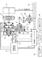
図1はVベルト式無段変速機の構成の概略を示すものである。
プライマリプーリ2およびセカンダリプーリ3が、両者のV溝が整列するように配置され、これらプーリ2、3のV溝にVベルト4が掛け渡されている。駆動源であるエンジン5をプライマリプーリ2と同軸に配置し、このエンジン5とプライマリプーリ2との間に、エンジン5から順次ロックアップ機構を有するトルクコンバータ6および前後進切り替え機構7を設ける。トルクコンバータ6、前後進切り替え機構7、プライマリプーリ2、セカンダリプーリ3およびVベルト4よりVベルト式無段変速機1が構成される。
Next, embodiments of the present invention will be described by way of examples.
FIG. 1 schematically shows the configuration of a V-belt type continuously variable transmission.
The primary pulley 2 and the
前後進切り替え機構7は、ダブルピニオン遊星歯車組7aを主たる構成要素とし、そのサンギヤをトルクコンバータ6を介してエンジン5に結合し、キャリアをプライマリプーリ2に結合する。前後進切り替え機構7は更に、ダブルピニオン遊星歯車組7aのサンギヤおよびキャリア間を直結する前進クラッチ7b、およびリングギヤを固定する後進ブレーキ7cを備え、前進クラッチ7bの締結時にエンジン5からトルクコンバータ6を経由した入力回転をそのままプライマリプーリ2に伝達する。また後進ブレーキ7cの締結時には、エンジン5からトルクコンバータ6を経由した入力回転を逆転減速してプライマリプーリ2へ伝達する。
The forward / reverse switching mechanism 7 includes a double pinion planetary gear set 7 a as a main component, and the sun gear is coupled to the
プライマリプーリ2の回転はVベルト4を介してセカンダリプーリ3に伝達され、セカンダリプーリ3の回転はその後、出力軸8、歯車組9およびディフアレンシヤルギヤ10を経て図示しない車輪へ伝達される。
上記の動力伝達中にプライマリプーリ2とセカンダリプーリ3との間における回転伝動比(変速比)を変更可能にするために、プライマリプーリ2およびセカンダリプーリ3のV溝を形成するフランジのうち一方を固定フランジ2a、3aとし、他方のフランジ2b、3bを軸線方向へ変位可能な可動フランジとする。これら可動フランジ2b、3bはそれぞれ、詳しくは後述するライン圧を基圧として作り出したプライマリプーリ圧Ppri、およびセカンダリプーリ圧Psecをプライマリプーリ室2cおよびセカンダリプーリ室3cに供給することにより固定フランジ2a、3a側に付勢され、Vベルト4を固定フランジ2aと可動フランジ2b間、および固定フランジ3aと可動フランジ3b間に摩擦係合させて、プライマリプーリ2とセカンダリプーリ3との間での前記動力伝達を可能にする。
The rotation of the primary pulley 2 is transmitted to the
In order to be able to change the rotational transmission ratio (transmission ratio) between the primary pulley 2 and the
なお本実施例においては特に、プライマリプーリ室2cおよびセカンダリプーリ室3cの受圧面積を同じにし、プーリ2、3の一方が大径になることのないようにし、これによりVベルト式無段変速機の小型化を図る。
また変速に際しては、後述のごとく目標変速比に対応させて発生させたプライマリプーリ圧Ppriおよびセカンダリプーリ圧Psec間の差圧により、両プーリ2、3のV溝幅を変更して、これらプーリ2、3に対するVベルト4の巻き掛け円弧径を連続的に変化させることで目標変速比を実現することができる。
In the present embodiment, in particular, the pressure receiving areas of the
Further, when shifting, the V groove widths of both
プライマリプーリ圧Ppriおよびセカンダリプーリ圧Psecの出力は、前進走行レンジの選択時に締結すべき前進クラッチ7bおよび後進走行レンジの選択時に締結すべき後進ブレーキ7cの締結油圧の出力と共に変速制御油圧回路11により制御し、この変速制御油圧回路11は変速機コントローラ12からの信号に応答して当該制御を行うものとする。
The outputs of the primary pulley pressure Ppri and the secondary pulley pressure Psec are output by the shift control
このため変速機コントローラ12には、プライマリプーリ回転数Npriを検出するプライマリプーリ回転センサ13からの信号と、セカンダリプーリ回転数Nsecを検出するセカンダリプーリ回転センサ14からの信号と、セカンダリプーリ圧Psecを検出するセカンダリプーリ圧センサ15からの信号と、アクセルペダル踏み込み量APOを検出するアクセル開度センサ16からの信号と、インヒビタスイッチ17からの選択レンジ信号と、変速作動油温TMPを検出する油温センサ18からの信号と、エンジン5の制御を行うエンジンコントローラ19からのエンジントルク情報に関連する信号(エンジン回転数や燃料噴射時間、エンジンの出力トルク情報など)とが入力される。
さらに変速機コントローラ12には、プライマリプーリ圧Ppriを検出するプライマリプーリ圧センサ30からの信号が入力されている。
For this reason, the
Further, the
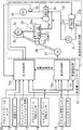
次に図2を用いて、変速制御油圧回路11および変速機コントローラ12で行われる制御について説明する。
変速制御油圧回路11は、エンジン駆動されるオイルポンプ21を備え、これから油路22への作動油を媒体として、これをプレッシャレギュレータ弁(P.Reg弁)23により所定のライン圧PLに調圧する。油路22のライン圧PLは、一方で減圧弁24により調圧されセカンダリプーリ圧Psecとしてセカンダリプーリ室(SEC)3cに供給され、他方で変速制御弁25により調圧されプライマリプーリ圧Ppriとしてプライマリプーリ室(PRI)2cに供給される。なお、プレッシャレギュレータ弁23は、ソレノイド23aへの駆動デューティーによりライン圧PLを制御し、減圧弁24は、ソレノイド24aへの駆動デューティーによりセカンダリプーリ圧Psecを制御するものとする。
Next, the control performed by the shift control
The shift control
変速制御弁25は、中立位置25aと、増圧位置25bと、減圧位置25cとを有し、これら弁位置を切り換えるために変速制御弁25を変速リンク26の中程に連結し、該変速リンク26の一端に、変速アクチュエータとしてのステップモータ(M)27を、また他端にプライマリプーリの可動フランジ2bを連結する。ステップモータ27は、基準位置から目標変速比に対応したステップ数だけ進んだ作動位置に駆動され、かかるステップモータ27の駆動により変速リンク26が可動フランジ2bとの連結部を支点にして揺動することにより、変速制御弁25を中立位置25aから増圧位置25bまたは減圧位置25cに変化させる。
The speed
その結果、目標変速比が高速側(アップシフト側)である場合にはライン圧PLがプライマリプーリ圧Ppri側と連通し、一方低速側(ダウンシフト側)である場合にはプライマリプーリ圧Ppriがドレン側と連通することとなる。これにより、プライマリプーリ圧Ppriがライン圧PLを基圧として増圧、またはドレンにより減圧され、セカンダリプーリ圧Psecとの差圧が変化することでHi側変速比へのアップシフトまたはLo側変速比へのダウンシフトを生じ、目標変速比に向けての変速動作が行われる。 As a result, when the target gear ratio is on the high speed side (upshift side), the line pressure PL communicates with the primary pulley pressure Ppri side. On the other hand, when the target gear ratio is on the low speed side (downshift side), the primary pulley pressure Ppri is It will communicate with the drain side. As a result, the primary pulley pressure Ppri is increased with the line pressure PL as the base pressure, or is reduced by the drain, and the differential pressure with the secondary pulley pressure Psec is changed so that the upshift to the Hi-side gear ratio or the Lo-side gear ratio. Downshift to the target gear ratio is performed.
当該変速の進行は、プライマリプーリの可動フランジ2bを介して変速リンク26にフイードバックされ、変速リンク26がステップモータ27との連結部を支点にして、変速制御弁25を増圧位置25bまたは減圧位置25cから中立位置25aに戻す方向へ揺動する。これにより、目標変速比が達成される時に変速制御弁25が中立位置25aに戻され、目標変速比を保つことができる。なお、プーリが最Lo位置にある場合には、プライマリプーリ圧Ppriの有無にかかわらず、図示しない機械的なストッパがプーリに反力を与えることとしているため、Vベルト4の伝達トルクの容量は確保されることとなっている。
The speed change is fed back to the
プレッシャレギュレータ弁23のソレノイド駆動デューティー、減圧弁24のソレノイド駆動デューティー、およびステップモータ27への変速指令(ステップ数)は、図1に示す前進クラッチ7bおよび後進ブレーキ7cへ締結油圧を供給するか否かの制御と共に変速機コントローラ12により決定し、このコントローラ12を図2に示すように圧力制御部12aおよび変速制御部12bで構成する。圧力制御部12aは、プレッシャレギュレータ弁23のソレノイド駆動デューティー、および減圧弁24のソレノイド駆動デューティーを決定し、変速制御部12bは以下のようにしてステップモータ27の駆動ステップ数Astepを決定する。
The solenoid drive duty of the
変速制御部12bはまず、車速検出部31を用いてセカンダリプーリ回転数Nsecから車速を求める。次に変速制御部12bは、求められた車速およびアクセルペダル踏み込み量APOを用いて予定の変速マップを基に目標入力回転数を求め、これをセカンダリプーリ回転数Nsecで除算することにより、運転状態(車速およびアクセルペダル踏み込み量APO)に応じた目標変速比を求める。
First, the
次いで、プライマリプーリ回転数Npriをセカンダリプーリ回転数Nsecで除算することにより実変速比(到達変速比)を演算し、上記目標変速比に対する実変速比の偏差に応じて外乱補償しながら実変速比を目標変速速度で目標変速比に漸近させるための変速比指令を求める。そして、この変速比指令を実現するためのステップモータ27のステップ数(ステップモータ27の作動位置)Astepを求め、これをステップモータ27に指令することで前記の変速動作により目標変速比を達成することができる。
Next, the actual speed ratio (reached speed ratio) is calculated by dividing the primary pulley speed Npri by the secondary pulley speed Nsec, and the actual speed ratio is compensated for disturbance according to the deviation of the actual speed ratio with respect to the target speed ratio. A speed ratio command for asymptotically approaching the target speed ratio at the target speed is obtained. Then, the step number of the step motor 27 (operation position of the step motor 27) Astep for realizing the gear ratio command is obtained, and this is commanded to the
次に、変速比の異常上昇時に変速機コントローラ12が行う処理について説明する。
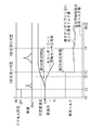
図3は、変速機コントローラ12が行う処理の流れを示すフローチャートであり、図4は、本制御における各部の動作を示すタイムチャートである。
本処理は、イグニッションスイッチがオンとなったときに開始される。
イグニッションスイッチがオン(時刻t0)となった後、図4に示すように時刻t1において運転者によってアクセルが踏まれる。
Next, a process performed by the
FIG. 3 is a flowchart showing the flow of processing performed by the
This process is started when the ignition switch is turned on.
After the ignition switch is turned on (time t0), the accelerator is stepped on by the driver at time t1, as shown in FIG.
エンジンからの動力が伝達されて、プライマリプーリ2が回転を始めると、セカンダリプーリ回転センサ14が故障している場合およびVベルト4に滑りが発生している場合には、プライマリプーリ回転センサ13によるプライマリプーリ2の回転数の検出のみが行われる。
When the power from the engine is transmitted and the primary pulley 2 starts to rotate, when the secondary
これによりプライマリプーリ回転センサ13によって検出された回転数を、セカンダリプーリ回転センサ14によって検出された回転数で除算することによって得られる変速比が、図4に実線で示すように時刻t1以降において異常上昇(低速(Low)側へ変化)する。
なお、セカンダリプーリ回転センサ14が正常であり、Vベルトに滑りが発生していない場合には、図4に破線で示すように変速比が減少(高速(Hi)側へ変化)する。
As a result, the speed ratio obtained by dividing the rotational speed detected by the primary pulley
When the secondary
ステップ300において変速機コントローラ12は、イグニッションスイッチがオンとなってからセカンダリプーリ回転数Nsecから求め得る車速が0km/h以外になったことがあるかどうかの判断を行い、車速が一度でも0km/h以外となったことがある場合(たとえば、図4の時刻t1からt2の間において破線で示すように、車速が検出された場合)にはセカンダリプーリ回転センサ14は機能しているものとしてステップ307へ進む。
一方、車速が0km/hを維持している場合にはステップ301へ進む。
In
On the other hand, when the vehicle speed is maintained at 0 km / h, the routine proceeds to step 301.
ステップ301において、変速機コントローラ12は車速検出部31を用い、プライマリプーリ回転センサ13およびセカンダリプーリ回転センサ14による検出結果より、車両の変速比を算出する。
ステップ302において変速機コントローラ12は、算出された変速比が所定変速比以上であるかどうかの判断を行う。
変速比が異常上昇して所定変速比以上となった場合(図4における時刻t2)には、ステップ303へ進む。
一方、変速比が所定変速比以上となっていない場合には、ステップ300に戻る。
In
In
When the gear ratio increases abnormally and becomes equal to or higher than the predetermined gear ratio (time t2 in FIG. 4), the process proceeds to step 303.
On the other hand, if the gear ratio is not greater than or equal to the predetermined gear ratio, the process returns to step 300.
ステップ303において、変速比が所定変速比以上の状態が第1の所定時間以上継続されたかどうかの判断を行い、第1の所定時間以上継続された場合(図4における時刻t3)にはステップ304へ進み、第1の所定時間以上継続されなかった場合にはステップ300へ戻り上述の処理を繰り返す。
In
ステップ304において変速機コントローラ12は、Vベルト4には滑りが発生しておらずセカンダリプーリ回転センサ14が故障しているものとするセカンダリプーリ回転センサ故障判定を行う。
ステップ305において変速機コントローラ12は、各プーリへ供給する油圧を生成する変速制御油圧回路11は正常であるものとして、セカンダリプーリ圧センサ15によって検出される実セカンダリプーリ圧にもとづく要求トルク値を、図4における時刻t3以降、エンジン5を制御するエンジンコントローラ19に対して指示する。
In
In
該要求トルク値の指示後、ステップ306において変速機コントローラ12は、車速が0km/hであるかどうかを判断し、車速が0km/h以外となるまではステップ305における処理を繰り返す。
一方、図4の時刻t3からt4の間で破線で示すように、車速が0km/h以外となった場合には、セカンダリプーリ回転センサ14が機能しており、Vベルト4に滑りが発生しているものとして、ステップ311へ進む。
なおこの場合には、ステップ304において判定したセカンダリプーリ回転センサ故障判定を、1回目の滑り判定であるものとしてステップ311へ進む。
After instructing the required torque value, the
On the other hand, as shown by a broken line between time t3 and t4 in FIG. 4, when the vehicle speed is other than 0 km / h, the secondary
In this case, the secondary pulley rotation sensor failure determination determined in
ステップ307、308において変速機コントローラ12は、上述のステップ301、302における処理と同様に、所定変速比以上の状態が、第1の所定時間以上継続されたかどうかの判断を行う。
所定変速比以上の状態が第1の所定時間以上継続された場合に、ステップ309において変速機コントローラ12は、車速が検出されたことによってセカンダリプーリ回転センサ14は正常に機能し、Vベルト4に滑りが発生しているものとする1回目の滑り判定(図4における時刻t3)を行い、ステップ310へ進む。
In
When the state of the predetermined speed ratio or more continues for the first predetermined time or longer, the
ステップ310において変速機コントローラ12は、セカンダリプーリ圧センサ15によって検出される実セカンダリプーリ圧にもとづく要求トルク値を、図4における時刻t3以降、エンジン5を制御するエンジンコントローラ19に対して指示する。
In
該要求トルク値の指示後、またはステップ306において車速が0km/h以外となると、ステップ311において変速機コントローラ12は、ステップ309またはステップ304において判定された1回目の滑り判定の状態が、第2の所定時間以上継続されたかどうかの判断を行い、第2の所定時間以上継続された場合にはステップ312へ進む。
一方、第2の所定時間以上継続されなかった場合や、変速比が所定変速比を下回った場合には、ステップ310へ戻り上述の処理を行う。
After the instruction of the required torque value or when the vehicle speed becomes other than 0 km / h in
On the other hand, when it is not continued for the second predetermined time or when the gear ratio is lower than the predetermined gear ratio, the process returns to step 310 to perform the above-described processing.
ステップ312において変速機コントローラ12は、Vベルト4の滑りが長時間におよんでいるものとして第2の滑り判定(図4における時刻t4)を行う。
ステップ313において変速機コントローラ12は、第2の滑り判定がされた時刻t4以降において、図4に破線で示すようにエンジンコントローラ19に対して、車両が自走可能程度の要求トルク値を指示する。
これによって時刻t4以降、低い要求トルク指令値が指示されて、Vベルト式無段変速機への入力トルクが減少し、Vベルト4の保護が行われる。
なお本実施例において、ステップ305、310、313が本発明における入力トルク制御手段を構成し、ステップ301が本発明における変速比算出手段を構成する。
In
In
Thus, after time t4, a low required torque command value is instructed, the input torque to the V-belt continuously variable transmission is reduced, and the V-belt 4 is protected.
In this embodiment, steps 305, 310, and 313 constitute input torque control means in the present invention, and step 301 constitutes gear ratio calculation means in the present invention.
本実施例は以上のように構成され、変速機コントローラ12は、車速が0km/hであり、かつ変速比が所定変速比以上の状態が第1の所定時間以上継続された場合に、セカンダリプーリ回転センサ14によって検出された実際のセカンダリプーリ圧にもとづいて、エンジンコントローラ19に対してエンジンの要求トルクの指示を行う。
これによってセカンダリプーリ回転センサ14に故障が発生した場合にも、実際に発生しているセカンダリプーリ圧に応じた入力トルクがプライマリプーリ2に入力されることにより、車両の動力性能を確保することができる。
The present embodiment is configured as described above, and the
As a result, even when a failure occurs in the secondary
変速機コントローラ12は、車速0km/h以外が一度でも検出されている場合に、変速比が異常上昇すると、まず1回目の滑り判定を行って、プライマリプーリ圧センサ30によって検出された実際に発生しているプライマリプーリ圧に応じたエンジンの要求トルク指示を行う。その後、変速比の異常上昇が継続されている場合には、変速機コントローラ12は2回目の滑り判定を行い、エンジンコントローラ19に対して、車両が自走可能程度の要求トルク値を指示する。
これによって、セカンダリプーリ回転センサ14が機能しており、実際にVベルト4に滑りが発生した場合には、2回目の滑り判定以降プライマリプーリ2へ自走可能程度の入力トルクが入力されることにより、Vベルト4の滑りを防止することができる。
The
As a result, the secondary
なお、本実施例において、プライマリプーリ2の回転数をプライマリプーリ回転センサ13を用いて検出するものとしたが、たとえばトルクコンバータ6の出力軸の回転数より検出することもできる。
同様にセカンダリプーリ3の回転数についても、セカンダリプーリ回転センサ14以外によって検出することもできる。
これにより、たとえばプライマリプーリの回転数をプライマリプーリ回転センサ13でなく、トルクコンバータ6の出力軸回転数より検出しているベルト式無段変速機においても、プライマリプーリ回転センサを追加することなく、上記油圧制御を行うことができる
In the present embodiment, the rotation speed of the primary pulley 2 is detected using the primary
Similarly, the rotational speed of the
Thereby, for example, in the belt-type continuously variable transmission that detects the rotation speed of the primary pulley not from the primary
なお、上記実施例ではエンジンの出力トルクを直接制御することを例示として述べたが、このトルク制限をプライマリプーリへの入力トルクを制限することによって行ってもよい。即ち、エンジンとプライマリプーリの間に介在するトルクコンバータによって当該制御を行ってもよく、また、エンジンとプライマリプーリとの間にモータやクラッチが介在している場合には、これらにより上記トルク制限を行うようにしてもよい。 In the above embodiment, the output torque of the engine is directly controlled as an example, but this torque limitation may be performed by limiting the input torque to the primary pulley. That is, the control may be performed by a torque converter interposed between the engine and the primary pulley, and when a motor or a clutch is interposed between the engine and the primary pulley, the torque limitation is performed by these. You may make it perform.
1 Vベルト式無段変速機
2 プライマリプーリ
3 セカンダリプーリ
4 Vベルト (ベルト)
5 エンジン
6 トルクコンバータ
7 前後進切り替え機構
11 変速制御油圧回路
12 変速機コントローラ
13 プライマリプーリ回転センサ (プライマリプーリ側回転数検出部)
14 セカンダリプーリ回転センサ (セカンダリプーリ側回転数検出部)
15 セカンダリプーリ圧センサ
16 アクセル開度センサ
17 インヒビタスイッチ
18 油温センサ
19 エンジンコントローラ
21 オイルポンプ
23 プレッシャレギュレータ弁
24 減圧弁
25 変速制御弁
26 変速リンク
27 ステップモータ
30 プライマリプーリ圧センサ
31 車速検出部
1 V-belt type continuously variable transmission 2
DESCRIPTION OF
14 Secondary pulley rotation sensor (Secondary pulley side rotation speed detector)
DESCRIPTION OF
Claims (4)
前記プライマリプーリの回転数を検出するプライマリプーリ側回転数検出部、およびセカンダリプーリの回転数を検出するセカンダリプーリ側回転数検出部より得られる両プーリの実変速比が目標変速比となるように、前記プライマリプーリおよびセカンダリプーリに、それぞれプライマリプーリ圧およびセカンダリプーリ圧を作用させるよう構成した車両用ベルト式無段変速機の入力トルク制御装置において、
前記セカンダリプーリに供給されるセカンダリプーリ圧を検出するセカンダリプーリ圧センサと、
前記プライマリプーリに入力される入力トルクの制御を行う入力トルク制御手段と、
前記セカンダリプーリ側回転数検出部による検出結果より車両の速度を検出する車速検出部と、
前記プライマリプーリ側回転数検出部およびセカンダリプーリ側回転数検出部による検出結果より、実変速比を算出する変速比算出手段とを備え、
前記入力トルク制御手段は、前記車速検出部によって車両の速度ゼロが検出された、かつ前記変速比算出手段によって算出された実変速比が所定変速比以上上昇した場合に、前記セカンダリプーリ圧センサによって検出されたセカンダリプーリ圧に応じた前記入力トルクの制御を行うことを特徴とする車両用ベルト式無段変速機の入力トルク制御装置。 A belt is passed between the primary pulley to which the input torque is input and the secondary pulley on the output side,
The actual gear ratio of both pulleys obtained from the primary pulley-side rotation speed detection unit that detects the rotation speed of the primary pulley and the secondary pulley-side rotation speed detection unit that detects the rotation speed of the secondary pulley is the target gear ratio. In the input torque control device for a belt type continuously variable transmission for a vehicle configured to apply a primary pulley pressure and a secondary pulley pressure to the primary pulley and the secondary pulley, respectively.
A secondary pulley pressure sensor for detecting a secondary pulley pressure supplied to the secondary pulley;
Input torque control means for controlling the input torque input to the primary pulley;
A vehicle speed detection unit for detecting the speed of the vehicle from the detection result by the secondary pulley side rotation speed detection unit;
A gear ratio calculating means for calculating an actual gear ratio from detection results by the primary pulley side rotation speed detection unit and the secondary pulley side rotation speed detection unit;
The input torque control means uses the secondary pulley pressure sensor when the vehicle speed detection unit detects that the vehicle speed is zero and the actual speed ratio calculated by the speed ratio calculation means increases by a predetermined speed ratio or more. An input torque control device for a belt type continuously variable transmission for a vehicle, wherein the input torque is controlled according to the detected secondary pulley pressure.
または、前記セカンダリプーリ側回転数検出部は、前記セカンダリプーリの回転数を直接検出するセカンダリプーリ回転センサが用いられることを特徴とする請求項1または2記載の車両用ベルト式無段変速機の入力トルク制御装置。 The primary pulley side rotation speed detection unit uses a primary pulley rotation sensor that directly detects the rotation speed of the primary pulley,
Alternatively, the secondary pulley-side rotation speed detection unit uses a secondary pulley rotation sensor that directly detects the rotation speed of the secondary pulley. Input torque control device.
Priority Applications (3)
| Application Number | Priority Date | Filing Date | Title |
|---|---|---|---|
| JP2004108200A JP2005291111A (en) | 2004-03-31 | 2004-03-31 | Input torque control device for belt type continuously variable transmission for vehicle |
| EP05251411A EP1582778A3 (en) | 2004-03-31 | 2005-03-09 | Input torque control system of belt-type continuously variable transmission for vehicle |
| US11/092,037 US7179196B2 (en) | 2004-03-31 | 2005-03-29 | Input torque control system of belt-type continuously variable transmission for vehicle |
Applications Claiming Priority (1)
| Application Number | Priority Date | Filing Date | Title |
|---|---|---|---|
| JP2004108200A JP2005291111A (en) | 2004-03-31 | 2004-03-31 | Input torque control device for belt type continuously variable transmission for vehicle |
Publications (1)
| Publication Number | Publication Date |
|---|---|
| JP2005291111A true JP2005291111A (en) | 2005-10-20 |
Family
ID=34880112
Family Applications (1)
| Application Number | Title | Priority Date | Filing Date |
|---|---|---|---|
| JP2004108200A Pending JP2005291111A (en) | 2004-03-31 | 2004-03-31 | Input torque control device for belt type continuously variable transmission for vehicle |
Country Status (3)
| Country | Link |
|---|---|
| US (1) | US7179196B2 (en) |
| EP (1) | EP1582778A3 (en) |
| JP (1) | JP2005291111A (en) |
Cited By (2)
| Publication number | Priority date | Publication date | Assignee | Title |
|---|---|---|---|---|
| JP2007315550A (en) * | 2006-05-29 | 2007-12-06 | Nissan Motor Co Ltd | Automatic transmission output shaft rotation speed estimation device, abnormality diagnosis device, and auto cruise control device |
| WO2017043409A1 (en) * | 2015-09-11 | 2017-03-16 | ジヤトコ株式会社 | Continuously variable transmission and malfunction determination method therefor |
Families Citing this family (13)
| Publication number | Priority date | Publication date | Assignee | Title |
|---|---|---|---|---|
| JP2005291395A (en) * | 2004-03-31 | 2005-10-20 | Jatco Ltd | Hydraulic control device for belt type continuously variable transmission for vehicle |
| JP4584856B2 (en) * | 2006-03-29 | 2010-11-24 | ジヤトコ株式会社 | Shift control device for automatic transmission |
| EP1972836B1 (en) * | 2007-03-20 | 2012-12-26 | Yamaha Hatsudoki Kabushiki Kaisha | Electronically-controlled continuously variable transmission |
| RU2483235C1 (en) | 2009-04-30 | 2013-05-27 | Ниссан Мотор Ко., Лтд | Control device and control method of belt stepless transmission |
| RU2490533C2 (en) | 2009-04-30 | 2013-08-20 | Ниссан Мотор Ко., Лтд | Device and method to control continuously variable transmission of belt type |
| BRPI0924736A2 (en) | 2009-04-30 | 2016-01-26 | Nissan Motor | belt type continuously variable transmission controller and control method |
| WO2010125666A1 (en) | 2009-04-30 | 2010-11-04 | ジヤトコ株式会社 | Belt‑based continuously variable transmission control device and control method |
| MX2011011418A (en) * | 2009-04-30 | 2012-02-13 | Nissan Motor | Controller and control method of belt type continuously variable transmission. |
| BR112012014707A2 (en) * | 2009-12-15 | 2016-04-12 | Nissan Motor | device and method for controlling a continuously variable belt-type transmission for a vehicle |
| JP4633197B1 (en) * | 2009-12-15 | 2011-02-16 | 日産自動車株式会社 | Control device and control method for belt type continuously variable transmission for vehicle |
| US9096211B2 (en) | 2012-03-14 | 2015-08-04 | Caterpillar Inc. | Control system having powertrain lock |
| US9151382B2 (en) * | 2014-02-24 | 2015-10-06 | GM Global Technology Operations LLC | Gross slip-based control of a variator assembly |
| CN107429833B (en) * | 2015-03-20 | 2019-05-21 | 加特可株式会社 | Transmission control device and transmission control method |
Family Cites Families (9)
| Publication number | Priority date | Publication date | Assignee | Title |
|---|---|---|---|---|
| DE19712451A1 (en) * | 1997-03-25 | 1998-10-01 | Bosch Gmbh Robert | Device and method for controlling a CVT in a motor vehicle |
| DE19712713A1 (en) * | 1997-03-26 | 1998-10-01 | Bosch Gmbh Robert | Device and method for controlling a CVT in a motor vehicle |
| DE19858263A1 (en) * | 1998-12-17 | 2000-06-21 | Zahnradfabrik Friedrichshafen | Method for monitoring a continuously variable transmission |
| JP4009053B2 (en) * | 2000-04-26 | 2007-11-14 | 三菱自動車工業株式会社 | Line pressure control device for belt type continuously variable transmission |
| JP2004068686A (en) * | 2002-08-05 | 2004-03-04 | Jatco Ltd | Engine torque control device |
| JP3993489B2 (en) * | 2002-08-26 | 2007-10-17 | ジヤトコ株式会社 | Belt slip prevention device for belt type continuously variable transmission |
| JP4107484B2 (en) * | 2002-09-27 | 2008-06-25 | ジヤトコ株式会社 | Shift control device for V-belt continuously variable automatic transmission |
| JP3981317B2 (en) * | 2002-10-04 | 2007-09-26 | ジヤトコ株式会社 | Hydraulic pressure drop detecting device for vehicle transmission |
| JP2004316843A (en) * | 2003-04-18 | 2004-11-11 | Jatco Ltd | Control device for belt-type continuously variable transmission |
-
2004
- 2004-03-31 JP JP2004108200A patent/JP2005291111A/en active Pending
-
2005
- 2005-03-09 EP EP05251411A patent/EP1582778A3/en not_active Withdrawn
- 2005-03-29 US US11/092,037 patent/US7179196B2/en not_active Expired - Fee Related
Cited By (4)
| Publication number | Priority date | Publication date | Assignee | Title |
|---|---|---|---|---|
| JP2007315550A (en) * | 2006-05-29 | 2007-12-06 | Nissan Motor Co Ltd | Automatic transmission output shaft rotation speed estimation device, abnormality diagnosis device, and auto cruise control device |
| WO2017043409A1 (en) * | 2015-09-11 | 2017-03-16 | ジヤトコ株式会社 | Continuously variable transmission and malfunction determination method therefor |
| CN108027054A (en) * | 2015-09-11 | 2018-05-11 | 日产自动车株式会社 | Belt-Type CVT and Its Fault Judgment Method |
| JPWO2017043409A1 (en) * | 2015-09-11 | 2018-06-28 | ジヤトコ株式会社 | Belt continuously variable transmission and failure judgment method thereof |
Also Published As
| Publication number | Publication date |
|---|---|
| EP1582778A3 (en) | 2007-07-18 |
| US7179196B2 (en) | 2007-02-20 |
| US20050221949A1 (en) | 2005-10-06 |
| EP1582778A2 (en) | 2005-10-05 |
Similar Documents
| Publication | Publication Date | Title |
|---|---|---|
| EP1939503B1 (en) | Continuously variable transmission and control method for continuously variable transmission | |
| KR101342332B1 (en) | Hydraulic Control Device for Belt Type Continuously Variable Transmission | |
| JP5605504B2 (en) | Control device for vehicle drive device | |
| JP2004125011A (en) | V-belt type continuously variable transmission anti-slip device | |
| JP4414972B2 (en) | Vehicle control device | |
| JP2005291111A (en) | Input torque control device for belt type continuously variable transmission for vehicle | |
| CN110094474B (en) | Control device for vehicle power transmission device | |
| JP4084777B2 (en) | Input torque control device for belt type continuously variable transmission for vehicle | |
| JP3898654B2 (en) | Engine torque control device | |
| US20060063641A1 (en) | Shift control apparatus and method for continuously variable transmission | |
| JP4071649B2 (en) | Shift control device for belt type continuously variable transmission | |
| JP2005291395A (en) | Hydraulic control device for belt type continuously variable transmission for vehicle | |
| KR101939527B1 (en) | Control device of transmission and control method of transmission | |
| KR101935190B1 (en) | Control device of transmission and control method of transmission | |
| KR101928685B1 (en) | Control device of transmission and control method of transmission | |
| JP4293768B2 (en) | Shift control device for continuously variable transmission | |
| JP2010216490A (en) | Belt slip ratio computing device for v-belt type continuously variable transmission | |
| KR101939526B1 (en) | Control device of transmission and control method of transmission | |
| US10605358B2 (en) | Transmission and control method for transmission |
Legal Events
| Date | Code | Title | Description |
|---|---|---|---|
| A621 | Written request for application examination |
Free format text: JAPANESE INTERMEDIATE CODE: A621 Effective date: 20050818 |
|
| A131 | Notification of reasons for refusal |
Free format text: JAPANESE INTERMEDIATE CODE: A131 Effective date: 20071106 |
|
| A02 | Decision of refusal |
Free format text: JAPANESE INTERMEDIATE CODE: A02 Effective date: 20080311 |