WO2023243149A1 - 水処理方法および水処理装置 - Google Patents
水処理方法および水処理装置 Download PDFInfo
- Publication number
- WO2023243149A1 WO2023243149A1 PCT/JP2023/006236 JP2023006236W WO2023243149A1 WO 2023243149 A1 WO2023243149 A1 WO 2023243149A1 JP 2023006236 W JP2023006236 W JP 2023006236W WO 2023243149 A1 WO2023243149 A1 WO 2023243149A1
- Authority
- WO
- WIPO (PCT)
- Prior art keywords
- water
- treated
- water treatment
- oxidizing agent
- cation exchanger
- Prior art date
- Legal status (The legal status is an assumption and is not a legal conclusion. Google has not performed a legal analysis and makes no representation as to the accuracy of the status listed.)
- Ceased
Links
Images
Classifications
-
- C—CHEMISTRY; METALLURGY
- C02—TREATMENT OF WATER, WASTE WATER, SEWAGE, OR SLUDGE
- C02F—TREATMENT OF WATER, WASTE WATER, SEWAGE, OR SLUDGE
- C02F1/00—Treatment of water, waste water, or sewage
- C02F1/42—Treatment of water, waste water, or sewage by ion-exchange
-
- C—CHEMISTRY; METALLURGY
- C02—TREATMENT OF WATER, WASTE WATER, SEWAGE, OR SLUDGE
- C02F—TREATMENT OF WATER, WASTE WATER, SEWAGE, OR SLUDGE
- C02F1/00—Treatment of water, waste water, or sewage
- C02F1/44—Treatment of water, waste water, or sewage by dialysis, osmosis or reverse osmosis
-
- C—CHEMISTRY; METALLURGY
- C02—TREATMENT OF WATER, WASTE WATER, SEWAGE, OR SLUDGE
- C02F—TREATMENT OF WATER, WASTE WATER, SEWAGE, OR SLUDGE
- C02F1/00—Treatment of water, waste water, or sewage
- C02F1/50—Treatment of water, waste water, or sewage by addition or application of a germicide or by oligodynamic treatment
-
- C—CHEMISTRY; METALLURGY
- C02—TREATMENT OF WATER, WASTE WATER, SEWAGE, OR SLUDGE
- C02F—TREATMENT OF WATER, WASTE WATER, SEWAGE, OR SLUDGE
- C02F1/00—Treatment of water, waste water, or sewage
- C02F1/72—Treatment of water, waste water, or sewage by oxidation
-
- C—CHEMISTRY; METALLURGY
- C02—TREATMENT OF WATER, WASTE WATER, SEWAGE, OR SLUDGE
- C02F—TREATMENT OF WATER, WASTE WATER, SEWAGE, OR SLUDGE
- C02F9/00—Multistage treatment of water, waste water or sewage
Definitions
- the present invention relates to a water treatment method and water treatment device that remove hardness components from water using a cation exchanger.
- a method of softening hard components in water to be treated using an ion exchanger and recovering the water by passing the water through a reverse osmosis membrane has been used.
- concentration of hardness components in the water to be treated is low, for example, 2 mg-CaCO 3 /L or less, there is sufficient exchange capacity of the ion exchanger, so the regeneration frequency will be longer, for example, once every few months. It can be operated with a small amount of regenerant.
- a strongly acidic cation exchange resin is used as the ion exchanger, but a weakly acidic cation exchange resin may be used if the coexisting salt concentration is high. It is also possible to use monolithic or fibrous cation exchangers.
- Patent Document 1 discloses a method of adding caustic soda to sterilize an ion exchanger.
- cleaning operations such as backwashing can be performed, but in the case of a resin tower filled with a flowing ion exchanger such as a spherical ion exchange resin, the ion exchanger filled with the cleaning operation
- a flowing ion exchanger such as a spherical ion exchange resin
- the ion exchanger filled with the cleaning operation The distribution of ionic forms is disrupted, and hard-form ion exchangers are present at the bottom of the packed bed, causing hardness leaks into the treated water, making regeneration operations necessary after cleaning operations. Become.
- An object of the present invention is to suppress the generation of slime while suppressing the deterioration of the cation exchanger in a water treatment method that uses a cation exchanger to remove hardness components from treated water containing hardness components.
- An object of the present invention is to provide a water treatment method and a water treatment device that can extend the frequency of regeneration of an ion exchanger.
- the present invention is a water treatment method in which hardness components are removed from treated water containing hardness components using a cation exchanger, in which an oxidizing agent is removed at an oxidizing agent concentration of 0.
- the water is added to the water to be treated in a range of 0.01 to 2.0 mg-Cl/L.
- the oxidizing agent is preferably a stabilized hypobromite composition containing a brominated oxidizing agent and a sulfamic acid compound.
- the cation exchanger is preferably a weakly acidic cation exchanger.
- the water to be treated may contain at least a portion of fluorine-containing abatement wastewater discharged from a semiconductor factory, and the treated water of the cation exchanger may be treated using a reverse osmosis membrane. preferable.
- the water to be treated preferably contains silica and is treated using a reverse osmosis membrane after the water treated by the cation exchanger is made alkaline.
- the water to be treated is passed through a packed tower filled with the cation exchanger, the differential pressure of the packed tower is measured, and the amount of the oxidizing agent added is adjusted according to the measured value. It is preferable to do so.
- the oxidizing agent is intermittently added to the water to be treated.
- the present invention is a water treatment apparatus equipped with an ion exchange treatment means for removing hardness components from water to be treated containing hardness components using a cation exchanger, wherein an oxidizing agent is oxidized at a stage upstream of the cation exchanger.
- the water treatment apparatus includes means for adding an oxidizing agent to the water to be treated so that the concentration of the oxidizing agent component is in the range of 0.01 to 2.0 mg-Cl/L.
- the oxidizing agent is preferably a stabilized hypobromite composition containing a brominated oxidizing agent and a sulfamic acid compound.
- the cation exchanger is preferably a weakly acidic cation exchanger.
- the water to be treated includes at least a portion of fluorine-containing detoxification wastewater discharged from a semiconductor factory, and reverse osmosis is performed in which the treated water of the cation exchanger is treated using a reverse osmosis membrane. It is preferable to further include membrane processing means.
- the water to be treated contains silica, and further includes a reverse osmosis membrane treatment means for making the water treated by the cation exchanger alkaline and then treating it using a reverse osmosis membrane.
- the reverse osmosis membrane treatment means is a packed tower filled with the cation exchanger, and the pressure difference in the packed tower is measured when the water to be treated is passed through the packed tower.
- the apparatus further includes a pressure measuring means and a controlling means for adjusting the amount of the oxidizing agent added according to the measured value.
- the oxidizing agent is intermittently added to the water to be treated.
- cation exchange in a water treatment method that uses a cation exchanger to remove hardness components from water to be treated containing hardness components, cation exchange It is possible to provide a water treatment method and a water treatment device that can extend the frequency of body regeneration.
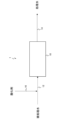
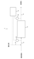
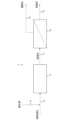
- 1 is a schematic configuration diagram showing an example of a water treatment device according to an embodiment of the present invention. It is a schematic block diagram which shows another example of the water treatment apparatus based on embodiment of this invention. It is a schematic block diagram which shows another example of the water treatment apparatus based on embodiment of this invention.
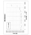
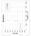
- 1 is a graph showing differential pressure (MPa) versus water flow rate (L/L-resin) in Example 1.
- 2 is a graph showing differential pressure (MPa) versus water flow rate (L/L-resin) in Comparative Example 1.
- FIG. 1 An example of a water treatment device according to an embodiment of the present invention is schematically shown in FIG. 1, and its configuration will be described.
- the water treatment device 1 includes an ion exchange treatment device 10 having a cation exchanger as an ion exchange treatment means for treating water to be treated using the cation exchanger.
- a treated water pipe 12 is connected to the treated water inlet of the ion exchange treatment device 10, and a treated water pipe 14 is connected to the treated water outlet.
- An oxidizing agent addition piping 16 is connected to the treated water piping 12 as an oxidizing agent addition means for adding an oxidizing agent to the treated water at a stage upstream of the ion exchange treatment device 10 .
- the water to be treated is sent to the ion exchange treatment device 10 through the water to be treated piping 12.
- an oxidizing agent is added to the treated water through the oxidizing agent addition piping 16 in the treated water piping 12 (oxidizing agent addition step), and the treated water to which the oxidizing agent has been added is sent to the ion exchange treatment device 10. be done.
- cation exchange treatment of the water to be treated is performed (cation exchange treatment step).
- the treated water that has been subjected to the cation exchange treatment is discharged through the treated water piping 14.
- a water tank to be treated that stores water to be treated may be installed upstream of the ion exchange treatment device 10.
- the oxidizing agent may be added to the water to be treated in the water tank to be treated, or may be added to the water to be treated in the water to be treated piping 12.
- the present inventors conducted an operation such that the water to be treated containing hardness components contained 0.05 to 2.0 mg-Cl/L of oxidizing agent components, thereby making the water to be treated containing hardness components contain cations. It has been found that in a water treatment method that uses an exchanger to remove hardness components, it is possible to suppress the deterioration of the cation exchanger and the generation of slime, thereby extending the regeneration frequency of the cation exchanger. It is possible to suppress the generation of slime, suppress the increase in differential pressure, and increase the frequency of cleaning without impairing the performance of the cation exchanger. If the cation exchanger is fluid, such as a spherical resin, the regeneration frequency can be increased. While minimizing the amount of regenerating agent, it is possible to suppress deterioration of the cation exchanger due to the oxidizing agent, extend the life of the cation exchanger, and provide optimized equipment.
- Cation exchangers tend to deteriorate due to oxidizing agents, and the exchange capacity decreases, but with this method, the degree of deterioration is not enough to affect the stable operation of the equipment, and the most efficient operation is possible. .
- FIG. 2 shows an example of a water treatment device having such a configuration.
- the water treatment device 3 shown in FIG. 2 includes a pressure gauge 20 as a differential pressure measuring means for measuring the differential pressure of the ion exchange treatment device 10.
- the water treatment device 3 may include a control device 18 as a control means for adjusting the amount of oxidizing agent added based on the differential pressure of the ion exchange treatment device 10.
- a treated water pipe 12 is connected to the treated water inlet of the ion exchange treatment device 10, and a treated water pipe 14 is connected to the treated water outlet.
- An oxidizing agent addition piping 16 is connected to the treated water piping 12 as an oxidizing agent addition means for adding an oxidizing agent to the treated water at a stage upstream of the ion exchange treatment device 10 .
- a pressure gauge 20 is installed in each of the treated water piping 12 and the treated water piping 14.
- the control device 18 has a wired or wireless electrical connection between each pressure gauge 20 and a pump, valve, etc., which is an oxidant addition amount adjustment means installed in the oxidant addition pipe 16. etc. are connected.
- the amount of the oxidizing agent added may be adjusted according to the differential pressure of the ion exchange treatment apparatus 10 measured by the pressure gauge 20.
- the control device 18 calculates the differential pressure of the ion exchange treatment device 10 based on the pressure measured by the pressure gauge 20, and based on the calculated differential pressure, a pump or valve installed in the oxidizing agent addition pipe 16, etc.
- the amount of the oxidizing agent added can be adjusted by controlling the amount of the oxidizing agent.
- cation exchanger There are no particular restrictions on the cation exchanger, but examples include cation exchange resins such as strongly acidic cation exchange resins and weakly acidic cation exchange resins that can remove cation components in water. A weakly acidic cation exchanger is preferable because it has a large cation exchanger and a high regeneration efficiency. As for the shape of the cation exchanger, in addition to the particulate cation exchange resin, a monolithic cation exchanger can also be used.
- the cation exchange resin may be a gel type or a macroporous type, but a macroporous cation exchange resin is preferable in terms of stain resistance, reaction rate, etc.
- the water holding capacity of the cation exchanger is, for example, in the range of 30 to 70%, and the total exchange capacity is, for example, in the range of 1.0 to 6.0 eq/L of resin.
- the ion exchange treatment device 10 is not particularly limited as long as it performs cation exchange treatment of the water to be treated using a cation exchanger, but for example, an ion exchange resin tower filled with a cation exchange resin, Examples include columns packed with a monolithic or fibrous cation exchanger.
- Water to be treated There are no particular restrictions on the water to be treated. Examples of the water to be treated include environmental water such as groundwater, river water, and seawater, recovered water, and wastewater such as abatement wastewater. Among these, softening treatment using a weakly acidic cation exchanger is effective for treating recovered water.
- Abatement wastewater is wastewater that is discharged after treating harmful gases used in semiconductor factories, etc. that perform semiconductor manufacturing processes with scrubbers, etc., and contains highly volatile components such as fluorine, ammonia, and organic components. It is wastewater.
- the water to be treated contains at least a portion of fluorine-containing abatement wastewater discharged from a semiconductor factory, it is preferable to treat the cation exchanger treated water using a reverse osmosis membrane.
- the water to be treated is abatement wastewater discharged from a semiconductor factory and contains a high concentration of fluorine
- the hardness of the water treated with cation exchange treatment should be reduced as much as possible in order to suppress the formation of calcium fluoride. Since it is desirable to keep it low, the water treatment method according to this embodiment can be effectively applied.
- the water treated by the cation exchanger may be adjusted to an alkaline pH range such as pH 9.5 to 12, which reduces membrane deterioration, preferably pH 10 to 11.5, which increases the solubility of silica. It is preferable to treat it using a reverse osmosis membrane after the treatment.
- the treated water is made alkaline after the cation exchange treatment and passed through the reverse osmosis membrane to suppress scale. Since it is desirable to keep the hardness component particularly low, the water treatment method according to this embodiment can be effectively applied.
- FIG. 3 shows an example of a water treatment device having a configuration that uses a reverse osmosis membrane to treat water treated by a cation exchanger.
- the water treatment device 5 shown in FIG. 3 includes a reverse osmosis membrane treatment device 22 as a reverse osmosis membrane treatment means for treating water treated by a cation exchanger using a reverse osmosis membrane.
- the treated water pipe 12 is connected to the treated water inlet of the ion exchange treatment device 10, and the treated water outlet of the ion exchange treatment device 10 and the inlet of the reverse osmosis membrane treatment device 22 are connected to the treated water pipe 12.
- the piping 14 is connected.
- a permeated water pipe 24 is connected to a permeated water outlet of the reverse osmosis membrane treatment device 22, and a concentrated water pipe 26 is connected to a concentrated water outlet.
- An oxidizing agent addition piping 16 is connected to the treated water piping 12 as an oxidizing agent addition means for adding an oxidizing agent to the treated water at a stage upstream of the ion exchange treatment device 10 .
- the water to be treated is sent to the ion exchange treatment device 10 through the water to be treated piping 12.
- an oxidizing agent is added to the treated water through the oxidizing agent addition piping 16 in the treated water piping 12 (oxidizing agent addition step), and the treated water to which the oxidizing agent has been added is sent to the ion exchange treatment device 10. be done.
- cation exchange treatment of the water to be treated is performed (cation exchange treatment step).
- the treated water that has been subjected to the cation exchange treatment is sent to the reverse osmosis membrane treatment device 22 through the treated water piping 14.
- reverse osmosis membrane treatment device 22 reverse osmosis membrane treatment is performed on the treated water of the cation exchanger (reverse osmosis membrane treatment step). Permeated water obtained by reverse osmosis membrane treatment is discharged through permeated water piping 24, and concentrated water is discharged through concentrated water piping 26.
- the oxidizing agent examples include a chlorine-based oxidizing agent, a brominated oxidizing agent, a stabilized hypochlorous acid composition containing a chlorinated oxidizing agent and a sulfamic acid compound, and a stabilized hypochlorous acid composition containing a brominated oxidizing agent and a sulfamic acid compound.
- examples include chemical hypobromite compositions.
- "Stabilized hypochlorous acid composition containing a chlorine-based oxidizing agent and a sulfamic acid compound” is a stabilized hypochlorous acid composition containing a mixture of a "chlorine-based oxidizing agent" and a “sulfamic acid compound”. Alternatively, it may be a stabilized hypochlorous acid composition containing "a reaction product of a chlorine-based oxidizing agent and a sulfamic acid compound.”
- "Stabilized hypobromite composition containing a brominated oxidizing agent and a sulfamic acid compound” is a stabilized hypobromite composition containing a mixture of a "brominated oxidizing agent” and a "sulfamic acid compound”. Alternatively, it may be a stabilized hypobromous acid composition containing "a reaction product of a brominated oxidizing agent and a sulfamic acid compound.”
- chlorine-based oxidizing agents include chlorine gas, chlorine dioxide, hypochlorous acid or its salts, chlorous acid or its salts, chloric acid or its salts, perchloric acid or its salts, chlorinated isocyanuric acid or its salts. etc.
- salts include alkali metal hypochlorite salts such as sodium hypochlorite and potassium hypochlorite, alkaline earth hypochlorite salts such as calcium hypochlorite and barium hypochlorite.
- alkali metal salts of chlorite such as sodium chlorite and potassium chlorite
- alkaline earth metal salts of chlorite such as barium chlorite
- other metal salts of chlorite such as nickel chlorite
- alkali metal chlorates such as ammonium chlorate, sodium chlorate, and potassium chlorate
- alkaline earth metal salts of chlorate such as calcium chlorate and barium chlorate.
- chlorine-based oxidizing agents may be used alone or in combination of two or more.
- sodium hypochlorite is preferably used from the viewpoint of ease of handling.
- Bromine-based oxidizing agents include bromine (liquid bromine), bromine chloride, bromate acid, bromate salts, hypobromite, and the like.
- Hypobromous acid may be produced by reacting a bromine compound such as sodium bromide with a chlorine-based oxidizing agent such as hypochlorous acid.
- Bromine compounds include sodium bromide, potassium bromide, lithium bromide, ammonium bromide, and hydrobromic acid. Among these, sodium bromide is preferred from the viewpoint of formulation cost and the like.
- the sulfamic acid compound is a compound represented by the following general formula (1).
- R 2 NSO 3 H (1) (In the formula, R is independently a hydrogen atom or an alkyl group having 1 to 8 carbon atoms.)
- sulfamic acid compounds include sulfamic acid (amidosulfuric acid) in which both of the two R groups are hydrogen atoms, N-methylsulfamic acid, N-ethylsulfamic acid, N-propylsulfamic acid, N- Sulfamic acid compounds in which one of the two R groups is a hydrogen atom and the other is an alkyl group having 1 to 8 carbon atoms, such as isopropylsulfamic acid and N-butylsulfamic acid, N,N-dimethylsulfamic acid, N, of two R groups such as N-diethylsulfamic acid, N,N-dipropylsulfamic acid, N,N-dibutylsulfamic acid, N-methyl-N-ethylsulfamic acid, N-methyl-N-propylsulfamic acid, etc.
- sulfamic acid amidosul
- examples include compounds, salts thereof, and the like.
- Examples of the sulfamate include alkali metal salts such as sodium salts and potassium salts, alkaline earth metal salts such as calcium salts, strontium salts, and barium salts, manganese salts, copper salts, zinc salts, iron salts, cobalt salts, Examples include other metal salts such as nickel salts, ammonium salts, guanidine salts, and the like.
- the sulfamic acid compounds and their salts may be used alone or in combination of two or more.
- As the sulfamic acid compound it is preferable to use sulfamic acid (amidosulfuric acid) from the viewpoint of environmental load and the like.
- the stabilized hypobromite composition may further contain an alkali.
- alkali include alkali hydroxides such as sodium hydroxide and potassium hydroxide. From the viewpoint of product stability at low temperatures, sodium hydroxide and potassium hydroxide may be used together. Moreover, the alkali may be used not in solid form but in the form of an aqueous solution.
- the stabilized hypobromous acid composition contains one containing bromine and a sulfamic acid compound, or one containing a mixture of bromine and a sulfamic acid compound, for example, one containing bromine and a sulfamic acid compound.
- a mixture of a sulfamic acid compound, an alkali, and water, or a mixture of a reaction product of bromine and a sulfamic acid compound for example, a mixture of a reaction product of bromine, a sulfamic acid compound, an alkali, and water. preferable.
- Stabilized hypobromite compositions especially stabilized hypobromite compositions containing bromine and a sulfamic acid compound, have a good bactericidal effect when compared to chlorine-based oxidizing agents such as hypochlorous acid.
- chlorine-based oxidizing agents such as hypochlorous acid.
- it hardly causes significant deterioration of cation exchangers like chlorine-based oxidizing agents such as hypochlorous acid.
- the effect on cation exchanger degradation is virtually negligible. Therefore, it is optimal as an oxidizing agent for use in cation exchangers.
- a stabilized hypobromite composition If a stabilized hypobromite composition is used, deterioration of the reverse osmosis membrane can be suppressed when a reverse osmosis membrane treatment device is installed after the ion exchange treatment device, so it can also be used to protect the reverse osmosis membrane. Become.
- the stabilized hypobromite composition can measure its concentration on-site in the same way as hypochlorous acid and the like, more accurate concentration control is possible.
- the pH of the stabilized hypobromite composition is, for example, greater than 13.0, and more preferably greater than 13.2. If the pH of the stabilized hypobromous acid composition is 13.0 or less, the available halogen in the stabilized hypobromous acid composition may become unstable.
- the bromate concentration in the stabilized hypobromite composition is preferably less than 5 mg/kg.
- the bromate concentration in the stabilized hypobromite composition is 5 mg/kg or more, the bromate ion concentration in the water to be treated may become high.
- the stabilized hypobromous acid composition is obtained by mixing a brominated oxidizing agent and a sulfamic acid compound, and may further include an alkali.
- a method for producing a stabilized hypobromous acid composition containing bromine and a sulfamic acid compound includes a step of adding bromine to a mixed solution containing water, an alkali, and a sulfamic acid compound under an inert gas atmosphere and causing a reaction, or The method preferably includes a step of adding bromine to a mixed solution containing water, an alkali, and a sulfamic acid compound under an inert gas atmosphere. By adding and reacting under an inert gas atmosphere, or by adding under an inert gas atmosphere, the bromate ion concentration in the stabilized hypobromite composition is reduced.
- the inert gas to be used is not limited, but at least one of nitrogen and argon is preferred from the viewpoint of manufacturing, etc., and nitrogen is particularly preferred from the viewpoint of manufacturing cost.
- the oxygen concentration in the reactor during the addition of bromine is preferably 6% or less, more preferably 4% or less, even more preferably 2% or less, and particularly preferably 1% or less. If the oxygen concentration in the reactor during the bromine reaction exceeds 6%, the amount of bromate produced in the reaction system may increase.
- the addition rate of bromine is preferably 25% by weight or less, more preferably 1% by weight or more and 20% by weight or less based on the total amount of the stabilized hypobromous acid composition.
- the addition rate of bromine exceeds 25% by weight based on the total amount of the stabilized hypobromous acid composition, the amount of bromic acid produced in the reaction system may increase. If it is less than 1% by weight, the detergency may be poor.
- the reaction temperature during bromine addition is preferably controlled within the range of 0°C or higher and 25°C or lower, but is more preferably controlled within the range of 0°C or higher and 15°C or lower in terms of production costs and the like. If the reaction temperature during bromine addition exceeds 25°C, the amount of bromic acid produced in the reaction system may increase; if it is below 0°C, freezing may occur.
- the oxidizing agent may be added to the water to be treated manually or automatically using an oxidizing agent injection pump or the like.
- the "chlorine-based oxidizing agent” and the “sulfamic acid compound” may be added to the water to be treated separately, or the undiluted solutions may be mixed together before being treated. It may be added to treated water.
- the "stabilized hypobromite composition” for example, the "brominated oxidizing agent” and the “sulfamic acid compound” may be added separately to the water to be treated, or the undiluted solutions may be mixed together before being treated. It may be added to treated water.
- the method of adding the oxidizing agent may be continuous addition, in which the oxidizing agent is continuously added to the water to be treated, or an addition period in which the oxidizing agent is added to the water to be treated, and a non-addition period in which the oxidizing agent is not added to the water to be treated. It may be added intermittently. Intermittent addition is preferable because it can shorten the contact time with the cation exchanger while maintaining the bactericidal effect and further reduce deterioration of the cation exchanger.
- the oxidizing agent may be added in the treated water piping 12, or may be added in the treated water tank provided separately.
- the amount of oxidizing agent in contact with the cation exchanger is 9,000,000 (mgCl 2 / L. h) is preferably at most 440 (mgCl 2 /L ⁇ h), more preferably at most 440 (mgCl 2 /L ⁇ h). If the CT value exceeds 9,000,000, the cation exchanger may deteriorate.
- a water treatment method for removing hardness components from treated water containing hardness components using a cation exchanger A water treatment method, wherein an oxidizing agent is added to the water to be treated before the cation exchanger so that the oxidizing agent component concentration is in the range of 0.01 to 2.0 mg-Cl/L.
- a water treatment method comprising passing the water to be treated through a packed tower filled with the cation exchanger, measuring a differential pressure in the packed tower, and adjusting the amount of the oxidizing agent added according to the measured value.
- a water treatment device comprising an ion exchange treatment means for removing hardness components from treated water containing hardness components using a cation exchanger, Water treatment, comprising an oxidizing agent addition means for adding an oxidizing agent to the water to be treated, upstream of the cation exchanger, so that the oxidizing agent component concentration is in the range of 0.01 to 2.0 mg-Cl/L.
- Water treatment comprising an oxidizing agent addition means for adding an oxidizing agent to the water to be treated, upstream of the cation exchanger, so that the oxidizing agent component concentration is in the range of 0.01 to 2.0 mg-Cl/L.
- a water treatment device wherein the oxidizing agent is a stabilized hypobromous acid composition containing a brominated oxidizing agent and a sulfamic acid compound.
- the water treatment device according to any one of [8] to [10],
- the water to be treated contains at least a portion of fluorine-containing abatement wastewater discharged from a semiconductor factory,
- a water treatment device further comprising a reverse osmosis membrane treatment means for treating the treated water of the cation exchanger using a reverse osmosis membrane.
- the water treatment device according to any one of [8] to [10], contains silica, A water treatment device further comprising a reverse osmosis membrane treatment means for making the water treated by the cation exchanger alkaline and then treating it using a reverse osmosis membrane.
- the water treatment device according to any one of [8] to [12],
- the reverse osmosis membrane treatment means is a packed tower filled with the cation exchanger, Differential pressure measuring means for measuring the differential pressure of the packed tower when the water to be treated is passed through the packed tower;
- a control means for adjusting the amount of the oxidizing agent added according to the measured value;
- a water treatment device further comprising:
- the oxidizing agent addition means intermittently adds the oxidizing agent to the water to be treated.
- a stabilized hypobromite composition was prepared by mixing the components.
- the stabilized hypobromite composition had a pH of 14 and a total chlorine concentration of 7.5% by weight.
- the total chlorine concentration is the value (mg-Cl 2 /L) measured by the total chlorine measurement method (DPD (diethyl-p-phenylenediamine) method) using HACH's multi-item water quality analyzer DR/4000.
- the detailed method for preparing the stabilized hypobromite composition is as follows.
- the pH of the resulting solution was 14 as measured by the glass electrode method.
- the bromine content of the resulting solution was determined to be 16.9% by converting bromine to iodine with potassium iodide, followed by redox titration using sodium thiosulfate, which was the theoretical content (16.9%). ) was 100.0%.
- the oxygen concentration in the reaction vessel during the bromine reaction was measured using "Oxygen Monitor JKO-02 LJDII" manufactured by Jiko Co., Ltd. Note that the bromate concentration was less than 5 mg/kg.
- Electrode type Glass electrode type pH meter: Manufactured by DKK Toa Co., Ltd., IOL-30 type
- Electrode calibration Neutral phosphate pH (6.86) standard solution (Type 2) manufactured by Kanto Kagaku Co., Ltd., boric acid manufactured by the same company
- Measurement temperature 25°C Performed with two-point calibration using salt pH (9.18) standard solution (Type 2)
- Measured value The electrode is immersed in the measurement solution, and the value after stabilization is taken as the measured value, and the average value of 3 measurements.
- Example 1 Under the test conditions shown below, water to be treated containing hardness components was treated to remove hardness components using a cation exchanger. Before the cation exchanger, an oxidizing agent was added to the water to be treated so that the concentration of the oxidizing agent component was within the following range.
- FIG. 4 shows the differential pressure (MPa) with respect to the water flow rate (L/L-resin) in Example 1.
- Example 1 approximately 55,000 times the amount of water could be passed until the differential pressure exceeded 0.04 MPa.
- Example 2 After the cation exchange resin AMBERLITE HPR8400 H (Na conversion product) was used under the conditions shown in Example 1, the total exchange capacity, water retention capacity, and microscopic observation (60x magnification) were analyzed, and the results are shown in Table 1. The following results were obtained. There was almost no change in the total exchange capacity or water holding capacity from the new value, and microscopic observation showed that there was almost no crushing, so no tendency for deterioration was observed. The total exchange capacity (eq/L/resin) and water retention capacity (%) of the ion exchange resin were measured as follows.
- the total exchange capacity was measured as follows. A weakly acidic cation exchange resin made into H-form by passing water through an aqueous HCl solution is brought to a moisture equilibrium state using a moisture controller, and then approximately 1 g (for measuring total exchange capacity) and 20 g are placed in two weighing bottles. (for wet volume measurement) at the same time. About 1 g of the weakly acidic cation exchange resin was weighed out and transferred to flask A with a capacity of 250 mL using a small amount of water, and then 200 mL of an aqueous solution of NaOH (4 g/L) containing NaCl (5 g/L) was added. Add more water to flask A up to the marked line.
- a Volume (mL) of the 50 mmol/L sulfuric acid aqueous solution required for the titration of the weakly acidic cation exchange resin
- b Volume of the 50 mmol/L sulfuric acid aqueous solution required for the titration of the blank test ( mL)
- f Factor of 50 mmol/L sulfuric acid aqueous solution
- w Mass of weakly acidic cation exchange resin for measuring total exchange capacity (about 1 g)
- w1 Mass of weakly acidic cation exchange resin for measuring wet volume ( (approximately 20 g)
- v wet volume (mL) of the weakly acidic cation exchange resin.
- the water retention capacity was measured as follows.
- the H-type weakly acidic cation exchange resin is brought to a moisture equilibrium state using a moisture controller and used as a sample resin.
- the water retention capacity M 1 (%) is calculated according to the following formula (B).
- M 1 (a/W) x 100 (B)
- W represents the mass (g) of the sample resin weighed in the flat weighing bottle
- a represents the difference in mass (g) before and after the flat weighing bottle.
- the method of the example can suppress the generation of slime while suppressing the deterioration of the cation exchanger in a water treatment method that uses a cation exchanger to remove hardness components from treated water containing hardness components.
- the regeneration frequency of the cation exchanger could be extended.
Landscapes
- Life Sciences & Earth Sciences (AREA)
- Hydrology & Water Resources (AREA)
- Engineering & Computer Science (AREA)
- Environmental & Geological Engineering (AREA)
- Water Supply & Treatment (AREA)
- Chemical & Material Sciences (AREA)
- Organic Chemistry (AREA)
- Separation Using Semi-Permeable Membranes (AREA)
- Treatment Of Water By Oxidation Or Reduction (AREA)
- Treatment Of Water By Ion Exchange (AREA)
Abstract
硬度成分を含む被処理水について陽イオン交換体を用いて硬度成分を除去する水処理方法において、陽イオン交換体の劣化を抑制しつつスライムの生成を抑制して、陽イオン交換体の再生頻度を延ばすことができる水処理方法を提供する。硬度成分を含む被処理水について陽イオン交換体を用いて硬度成分を除去する水処理方法であって、陽イオン交換体の前段において、酸化剤を酸化剤成分濃度が0.01~2.0mg-Cl/Lの範囲となるように前記被処理水に添加する、水処理方法である。
Description
本発明は、陽イオン交換体を用いて、水中の硬度成分を除去する水処理方法および水処理装置に関する。
被処理水中の硬度成分をイオン交換体によって軟化し、逆浸透膜に通水して水回収する方法が行われている。被処理水中の硬度成分濃度が例えば2mg-CaCO3/L以下と低い場合は、イオン交換体の交換容量に余裕があるため、再生頻度は長くなり、例えば数か月に1回程度でよく、少ない再生剤量で運転することができる。
一般的に、イオン交換体としては、強酸性の陽イオン交換樹脂が使用されるが、共存の塩濃度が高い場合等は、弱酸性の陽イオン交換樹脂が使用されることもある。また、モノリス状または繊維状の陽イオン交換体を使用することもできる。
被処理水が生物処理水や除害系排水等の有機物を含む排水である場合は、イオン交換体の交換容量には余裕があっても、スライムの生成によって、短期間、例えば2週間に1回程度でイオン交換体の洗浄や再生を行う必要があり、再生剤量および洗浄水量が増加するという課題がある。スライムの生成を抑制するために、次亜塩素酸等の酸化剤を被処理水に添加する方法が考えられるが、次亜塩素酸等の酸化剤はイオン交換体を劣化させるため、通常はイオン交換体に殺菌剤を添加することは行われていない。例えば、特許文献1には、イオン交換体の殺菌のために、苛性ソーダの添加方法を工夫する方法が開示されている。
スライム排除のためだけであれば、逆洗等の洗浄操作を行えばよいが、球状のイオン交換樹脂等の流動するイオン交換体を充填した樹脂塔の場合は、洗浄操作によって充填したイオン交換体のイオン形の分布が崩れてしまい、硬度形のイオン交換体が充填層の下部にも存在するようになり、処理水への硬度リークが発生してしまうため、洗浄操作後に再生操作が必要になる。
本発明の目的は、硬度成分を含む被処理水について陽イオン交換体を用いて硬度成分を除去する水処理方法において、陽イオン交換体の劣化を抑制しつつスライムの生成を抑制して、陽イオン交換体の再生頻度を延ばすことができる水処理方法および水処理装置を提供することにある。
本発明は、硬度成分を含む被処理水について陽イオン交換体を用いて硬度成分を除去する水処理方法であって、前記陽イオン交換体の前段において、酸化剤を酸化剤成分濃度が0.01~2.0mg-Cl/Lの範囲となるように前記被処理水に添加する、水処理方法である。
前記水処理方法において、前記酸化剤が、臭素系酸化剤とスルファミン酸化合物とを含む安定化次亜臭素酸組成物であることが好ましい。
前記水処理方法において、前記陽イオン交換体が、弱酸性の陽イオン交換体であることが好ましい。
前記水処理方法において、前記被処理水が、半導体工場から排出されるフッ素を含む除害系排水を少なくとも一部含み、逆浸透膜を用いて前記陽イオン交換体の処理水を処理することが好ましい。
前記水処理方法において、前記被処理水が、シリカを含み、前記陽イオン交換体の処理水をアルカリ性にした後に逆浸透膜を用いて処理することが好ましい。
前記水処理方法において、前記陽イオン交換体を充填した充填塔に前記被処理水を通水し、前記充填塔の差圧を測定し、その測定値に応じて前記酸化剤の添加量を調整することが好ましい。
前記水処理方法において、前記酸化剤を前記被処理水に間欠的に添加することが好ましい。
本発明は、硬度成分を含む被処理水について陽イオン交換体を用いて硬度成分を除去するイオン交換処理手段を備える水処理装置であって、前記陽イオン交換体の前段において、酸化剤を酸化剤成分濃度が0.01~2.0mg-Cl/Lの範囲となるように前記被処理水に添加する酸化剤添加手段を備える、水処理装置である。
前記水処理装置において、前記酸化剤が、臭素系酸化剤とスルファミン酸化合物とを含む安定化次亜臭素酸組成物であることが好ましい。
前記水処理装置において、前記陽イオン交換体が、弱酸性の陽イオン交換体であることが好ましい。
前記水処理装置において、前記被処理水が、半導体工場から排出されるフッ素を含む除害系排水を少なくとも一部含み、逆浸透膜を用いて前記陽イオン交換体の処理水を処理する逆浸透膜処理手段をさらに備えることが好ましい。
前記水処理装置において、前記被処理水が、シリカを含み、前記陽イオン交換体の処理水をアルカリ性にした後に逆浸透膜を用いて処理する逆浸透膜処理手段をさらに備えることが好ましい。
前記水処理装置において、前記逆浸透膜処理手段が前記陽イオン交換体を充填した充填塔であり、前記充填塔に前記被処理水を通水したときの前記充填塔の差圧を測定する差圧測定手段と、その測定値に応じて前記酸化剤の添加量を調整する制御手段と、をさらに備えることが好ましい。
前記水処理装置において、前記酸化剤を前記被処理水に間欠的に添加することが好ましい。
本発明によって、硬度成分を含む被処理水について陽イオン交換体を用いて硬度成分を除去する水処理方法において、陽イオン交換体の劣化を抑制しつつスライムの生成を抑制して、陽イオン交換体の再生頻度を延ばすことができる水処理方法および水処理装置を提供することができる。
本発明の実施の形態について以下説明する。本実施形態は本発明を実施する一例であって、本発明は本実施形態に限定されるものではない。
本発明の実施形態に係る水処理装置の一例の概略を図1に示し、その構成について説明する。
<水処理方法および水処理装置>
水処理装置1は、陽イオン交換体を用いて被処理水を処理するイオン交換処理手段として、陽イオン交換体を有するイオン交換処理装置10を備える。
水処理装置1は、陽イオン交換体を用いて被処理水を処理するイオン交換処理手段として、陽イオン交換体を有するイオン交換処理装置10を備える。
図1の水処理装置1において、イオン交換処理装置10の被処理水入口には、被処理水配管12が接続され、処理水出口には処理水配管14が接続されている。被処理水配管12には、イオン交換処理装置10の前段において、酸化剤を被処理水に添加する酸化剤添加手段として、酸化剤添加配管16が接続されている。
本実施形態に係る水処理方法および水処理装置1の動作について説明する。
被処理水は、被処理水配管12を通してイオン交換処理装置10へ送液される。ここで、被処理水配管12において酸化剤添加配管16を通して、酸化剤が被処理水に添加され(酸化剤添加工程)、酸化剤が添加された被処理水がイオン交換処理装置10へ送液される。イオン交換処理装置10において、被処理水の陽イオン交換処理が行われる(陽イオン交換処理工程)。陽イオン交換処理が行われた処理水は、処理水配管14を通して排出される。
イオン交換処理装置10の前段に、被処理水を貯留する被処理水槽を設置してもよい。その場合、酸化剤は、被処理水槽において被処理水に添加されてもよいし、被処理水配管12において被処理水に添加されてもよい。
本発明者らは、硬度成分が含まれる被処理水に、酸化剤成分が0.05~2.0mg-Cl/L含まれるように運転することによって、硬度成分を含む被処理水について陽イオン交換体を用いて硬度成分を除去する水処理方法において、陽イオン交換体の劣化を抑制しつつスライムの生成を抑制して、陽イオン交換体の再生頻度を延ばすことができることを見出した。陽イオン交換体の性能をほとんど損ねることなく、スライムの生成を抑制して差圧の上昇を抑え、洗浄頻度を伸ばすことができる。陽イオン交換体が球状樹脂等、流動性である場合は、再生頻度も伸ばすことができる。再生剤量を最小化しつつ、陽イオン交換体の酸化剤による劣化も抑制して寿命を延ばし、最適化した設備を提供することができる。
酸化剤によって陽イオン交換体は劣化傾向にあり、交換容量は減少するが、本方法であればその劣化度は装置の安定運転に影響を及ぼすほどではなく、最も効率的な運転が可能となる。
陽イオン交換体を充填した充填塔に被処理水を通水し、充填塔の差圧を測定し、その測定値に応じて酸化剤の添加量を調整することが好ましい。これによって、より効果的に運用することができる。図2に、このような構成を有する水処理装置の一例を示す。
図2に示す水処理装置3は、イオン交換処理装置10の差圧を測定する差圧測定手段として、圧力計20を備える。水処理装置3は、イオン交換処理装置10の差圧に基づいて酸化剤の添加量を調整する制御手段として、制御装置18を備えてもよい。
水処理装置3において、イオン交換処理装置10の被処理水入口には、被処理水配管12が接続され、処理水出口には処理水配管14が接続されている。被処理水配管12には、イオン交換処理装置10の前段において、酸化剤を被処理水に添加する酸化剤添加手段として、酸化剤添加配管16が接続されている。被処理水配管12および処理水配管14には、圧力計20がそれぞれ設置されている。制御装置18は、それぞれの圧力計20と、酸化剤添加配管16に設置された酸化剤の添加量を調整する酸化剤添加量調整手段であるポンプやバルブ等と、有線または無線の電気的接続等によって、接続されている。
例えば、圧力計20によって測定されたイオン交換処理装置10の差圧に応じて酸化剤の添加量を調整すればよい。例えば、制御装置18が圧力計20によって測定された圧力に基づいてイオン交換処理装置10の差圧を算出し、算出した差圧に基づいて、酸化剤添加配管16に設置されたポンプまたはバルブ等を制御して、酸化剤の添加量を調整すればよい。
[陽イオン交換体]
陽イオン交換体に特に制限はないが、水中の陽イオン成分を除去することができる強酸性の陽イオン交換樹脂、弱酸性の陽イオン交換樹脂等の陽イオン交換樹脂等が挙げられ、交換容量が大きい、再生効率が高い等の点で、弱酸性の陽イオン交換体であることが好ましい。陽イオン交換体の形状は、粒状の陽イオン交換樹脂の他に、モノリス形状の陽イオン交換体も使用することができる。
陽イオン交換体に特に制限はないが、水中の陽イオン成分を除去することができる強酸性の陽イオン交換樹脂、弱酸性の陽イオン交換樹脂等の陽イオン交換樹脂等が挙げられ、交換容量が大きい、再生効率が高い等の点で、弱酸性の陽イオン交換体であることが好ましい。陽イオン交換体の形状は、粒状の陽イオン交換樹脂の他に、モノリス形状の陽イオン交換体も使用することができる。
陽イオン交換樹脂は、ゲル型であっても、マクロポーラス型であってもよいが、耐汚染性、反応速度等の点で、マクロポーラス型の陽イオン交換樹脂であることが好ましい。
陽イオン交換体の水分保有能力は、例えば、30~70%の範囲であり、総交換容量は、例えば、1.0~6.0eq/L・樹脂の範囲である。
イオン交換処理装置10は、陽イオン交換体を用いて被処理水の陽イオン交換処理を行うものであればよく、特に制限はないが、例えば、陽イオン交換樹脂を充填したイオン交換樹脂塔、モノリス状または繊維状の陽イオン交換体を充填したカラム等が挙げられる。
[被処理水]
被処理水に特に制限はない。被処理水として、例えば、地下水、河川水、海水等の環境水や、回収水、除害系排水等の排水等が挙げられる。その中で、回収水の処理に関しては、弱酸性陽イオン交換体による軟化処理が効果的である。
被処理水に特に制限はない。被処理水として、例えば、地下水、河川水、海水等の環境水や、回収水、除害系排水等の排水等が挙げられる。その中で、回収水の処理に関しては、弱酸性陽イオン交換体による軟化処理が効果的である。
除害系排水とは、半導体製造工程を行う半導体工場等で使用される有害ガスをスクラバー等で処理して排水されたもので、例えばフッ素、アンモニア、有機成分等の揮発性の高い成分を含む排水である。
被処理水が、半導体工場から排出されるフッ素を含む除害系排水を少なくとも一部含む場合、逆浸透膜を用いて陽イオン交換体の処理水を処理することが好ましい。
被処理水が半導体工場から排出される除害系排水であって、フッ素を高濃度に含む場合には、フッ化カルシウムの生成を抑制するために、陽イオン交換処理の処理水の硬度はできるだけ低く抑えることが望ましいため、本実施形態に係る水処理方法を効果的に適用することができる。
また、被処理水がシリカを含む場合、陽イオン交換体の処理水を例えば膜の劣化が少ないpH9.5~12程度、好ましくはpH10~11.5程度の範囲のシリカの溶解度が高くなるアルカリ性にした後に逆浸透膜を用いて処理することが好ましい。
特にシリカを含む被処理水を処理するために、陽イオン交換処理の後段で陽イオン交換処理の処理水をアルカリ性にして逆浸透膜に通水するシステムにおいては、スケール抑制のために処理水中の硬度成分は特に低く抑えることが望ましいため、本実施形態に係る水処理方法を効果的に適用することができる。
図3に、これらのような、逆浸透膜を用いて陽イオン交換体の処理水を処理する構成を有する水処理装置の一例を示す。
図3に示す水処理装置5は、逆浸透膜を用いて陽イオン交換体の処理水を処理する逆浸透膜処理手段として、逆浸透膜処理装置22を備える。
水処理装置5において、イオン交換処理装置10の被処理水入口には、被処理水配管12が接続され、イオン交換処理装置10の処理水出口と逆浸透膜処理装置22の入口とは処理水配管14によりが接続されている。逆浸透膜処理装置22の透過水出口には、透過水配管24が接続され、濃縮水出口には、濃縮水配管26が接続されている。被処理水配管12には、イオン交換処理装置10の前段において、酸化剤を被処理水に添加する酸化剤添加手段として、酸化剤添加配管16が接続されている。
被処理水は、被処理水配管12を通してイオン交換処理装置10へ送液される。ここで、被処理水配管12において酸化剤添加配管16を通して、酸化剤が被処理水に添加され(酸化剤添加工程)、酸化剤が添加された被処理水がイオン交換処理装置10へ送液される。イオン交換処理装置10において、被処理水の陽イオン交換処理が行われる(陽イオン交換処理工程)。陽イオン交換処理が行われた処理水は、処理水配管14を通して逆浸透膜処理装置22へ送液される。逆浸透膜処理装置22において、陽イオン交換体の処理水について逆浸透膜処理が行われる(逆浸透膜処理工程)。逆浸透膜処理で得られた透過水は、透過水配管24を通して排出され、濃縮水は、濃縮水配管26を通して排出される。
[酸化剤]
酸化剤としては、例えば、塩素系酸化剤、臭素系酸化剤や、塩素系酸化剤とスルファミン酸化合物とを含む安定化次亜塩素酸組成物、臭素系酸化剤とスルファミン酸化合物とを含む安定化次亜臭素酸組成物等が挙げられる。
酸化剤としては、例えば、塩素系酸化剤、臭素系酸化剤や、塩素系酸化剤とスルファミン酸化合物とを含む安定化次亜塩素酸組成物、臭素系酸化剤とスルファミン酸化合物とを含む安定化次亜臭素酸組成物等が挙げられる。
「塩素系酸化剤とスルファミン酸化合物とを含む安定化次亜塩素酸組成物」は、「塩素系酸化剤」と「スルファミン酸化合物」との混合物を含む安定化次亜塩素酸組成物であってもよいし、「塩素系酸化剤とスルファミン酸化合物との反応生成物」を含む安定化次亜塩素酸組成物であってもよい。「臭素系酸化剤とスルファミン酸化合物とを含む安定化次亜臭素酸組成物」は、「臭素系酸化剤」と「スルファミン酸化合物」との混合物を含む安定化次亜臭素酸組成物であってもよいし、「臭素系酸化剤とスルファミン酸化合物との反応生成物」を含む安定化次亜臭素酸組成物であってもよい。
塩素系酸化剤としては、例えば、塩素ガス、二酸化塩素、次亜塩素酸またはその塩、亜塩素酸またはその塩、塩素酸またはその塩、過塩素酸またはその塩、塩素化イソシアヌル酸またはその塩等が挙げられる。これらのうち、塩としては、例えば、次亜塩素酸ナトリウム、次亜塩素酸カリウム等の次亜塩素酸アルカリ金属塩、次亜塩素酸カルシウム、次亜塩素酸バリウム等の次亜塩素酸アルカリ土類金属塩、亜塩素酸ナトリウム、亜塩素酸カリウム等の亜塩素酸アルカリ金属塩、亜塩素酸バリウム等の亜塩素酸アルカリ土類金属塩、亜塩素酸ニッケル等の他の亜塩素酸金属塩、塩素酸アンモニウム、塩素酸ナトリウム、塩素酸カリウム等の塩素酸アルカリ金属塩、塩素酸カルシウム、塩素酸バリウム等の塩素酸アルカリ土類金属塩等が挙げられる。これらの塩素系酸化剤は、1種を単独で用いても、2種以上を組み合わせて用いてもよい。塩素系酸化剤としては、取り扱い性等の点から、次亜塩素酸ナトリウムを用いるのが好ましい。
臭素系酸化剤としては、臭素(液体臭素)、塩化臭素、臭素酸、臭素酸塩、次亜臭素酸等が挙げられる。次亜臭素酸は、臭化ナトリウム等の臭素化合物と次亜塩素酸等の塩素系酸化剤とを反応させて生成させたものであってもよい。
臭素化合物としては、臭化ナトリウム、臭化カリウム、臭化リチウム、臭化アンモニウムおよび臭化水素酸等が挙げられる。これらのうち、製剤コスト等の点から、臭化ナトリウムが好ましい。
スルファミン酸化合物は、以下の一般式(1)で示される化合物である。
R2NSO3H (1)
(式中、Rは独立して水素原子または炭素数1~8のアルキル基である。)
R2NSO3H (1)
(式中、Rは独立して水素原子または炭素数1~8のアルキル基である。)
スルファミン酸化合物としては、例えば、2個のR基の両方が水素原子であるスルファミン酸(アミド硫酸)の他に、N-メチルスルファミン酸、N-エチルスルファミン酸、N-プロピルスルファミン酸、N-イソプロピルスルファミン酸、N-ブチルスルファミン酸等の2個のR基の一方が水素原子であり、他方が炭素数1~8のアルキル基であるスルファミン酸化合物、N,N-ジメチルスルファミン酸、N,N-ジエチルスルファミン酸、N,N-ジプロピルスルファミン酸、N,N-ジブチルスルファミン酸、N-メチル-N-エチルスルファミン酸、N-メチル-N-プロピルスルファミン酸等の2個のR基の両方が炭素数1~8のアルキル基であるスルファミン酸化合物、N-フェニルスルファミン酸等の2個のR基の一方が水素原子であり、他方が炭素数6~10のアリール基であるスルファミン酸化合物、またはこれらの塩等が挙げられる。スルファミン酸塩としては、例えば、ナトリウム塩、カリウム塩等のアルカリ金属塩、カルシウム塩、ストロンチウム塩、バリウム塩等のアルカリ土類金属塩、マンガン塩、銅塩、亜鉛塩、鉄塩、コバルト塩、ニッケル塩等の他の金属塩、アンモニウム塩およびグアニジン塩等が挙げられる。スルファミン酸化合物およびこれらの塩は、1種を単独で用いても、2種以上を組み合わせて用いてもよい。スルファミン酸化合物としては、環境負荷等の点から、スルファミン酸(アミド硫酸)を用いるのが好ましい。
安定化次亜臭素酸組成物は、さらにアルカリを含んでもよい。アルカリとしては、水酸化ナトリウム、水酸化カリウム等の水酸化アルカリ等が挙げられる。低温の製品安定性等の点から、水酸化ナトリウムと水酸化カリウムとを併用してもよい。また、アルカリは、固形でなく、水溶液として用いてもよい。
安定化次亜臭素酸組成物としては、陽イオン交換体をより劣化させないため、臭素と、スルファミン酸化合物とを含有するもの、または臭素とスルファミン酸化合物の混合物を含有するもの、例えば、臭素とスルファミン酸化合物とアルカリと水との混合物、または、臭素とスルファミン酸化合物との反応生成物を含有するもの、例えば、臭素とスルファミン酸化合物との反応生成物と、アルカリと、水との混合物が好ましい。
安定化次亜臭素酸組成物、特に臭素とスルファミン酸化合物とを含む安定化次亜臭素酸組成物は、次亜塩素酸等の塩素系酸化剤と比較すると、良好な殺菌効果を有しながらも、次亜塩素酸等の塩素系酸化剤のような著しい陽イオン交換体の劣化をほとんど引き起こすことがない。通常の使用濃度では、陽イオン交換体の劣化への影響は実質的に無視することができる。このため、陽イオン交換体に用いる酸化剤としては最適である。安定化次亜臭素酸組成物を用いれば、イオン交換処理装置の後段に逆浸透膜処理装置を備える場合には、逆浸透膜の劣化を抑制することができるため、逆浸透膜の保護にもなる。
安定化次亜臭素酸組成物は、次亜塩素酸等と同様に現場で濃度を測定することができるため、より正確な濃度管理が可能である。
安定化次亜臭素酸組成物のpHは、例えば、13.0超であり、13.2超であることがより好ましい。安定化次亜臭素酸組成物のpHが13.0以下であると安定化次亜臭素酸組成物中の有効ハロゲンが不安定になる場合がある。
安定化次亜臭素酸組成物中の臭素酸濃度は、5mg/kg未満であることが好ましい。安定化次亜臭素酸組成物中の臭素酸濃度が5mg/kg以上であると、被処理水の臭素酸イオン濃度が高くなる場合がある。
(安定化次亜臭素酸組成物の製造方法)
安定化次亜臭素酸組成物は、臭素系酸化剤とスルファミン酸化合物とを混合することにより得られ、さらにアルカリを混合してもよい。
安定化次亜臭素酸組成物は、臭素系酸化剤とスルファミン酸化合物とを混合することにより得られ、さらにアルカリを混合してもよい。
臭素とスルファミン酸化合物とを含む安定化次亜臭素酸組成物の製造方法としては、水、アルカリおよびスルファミン酸化合物を含む混合液に臭素を不活性ガス雰囲気下で添加して反応させる工程、または、水、アルカリおよびスルファミン酸化合物を含む混合液に臭素を不活性ガス雰囲気下で添加する工程を含むことが好ましい。不活性ガス雰囲気下で添加して反応させる、または、不活性ガス雰囲気下で添加することにより、安定化次亜臭素酸組成物中の臭素酸イオン濃度が低くなる。
用いる不活性ガスとしては限定されないが、製造等の面から窒素およびアルゴンのうち少なくとも1つが好ましく、特に製造コスト等の面から窒素が好ましい。
臭素の添加の際の反応器内の酸素濃度は6%以下が好ましいが、4%以下がより好ましく、2%以下がさらに好ましく、1%以下が特に好ましい。臭素の反応の際の反応器内の酸素濃度が6%を超えると、反応系内の臭素酸の生成量が増加する場合がある。
臭素の添加率は、安定化次亜臭素酸組成物全体の量に対して25重量%以下であることが好ましく、1重量%以上20重量%以下であることがより好ましい。臭素の添加率が安定化次亜臭素酸組成物全体の量に対して25重量%を超えると、反応系内の臭素酸の生成量が増加する場合がある。1重量%未満であると、洗浄力が劣る場合がある。
臭素添加の際の反応温度は、0℃以上25℃以下の範囲に制御することが好ましいが、製造コスト等の面から、0℃以上15℃以下の範囲に制御することがより好ましい。臭素添加の際の反応温度が25℃を超えると、反応系内の臭素酸の生成量が増加する場合があり、0℃未満であると、凍結する場合がある。
[酸化剤の添加方法]
酸化剤は、酸化剤注入ポンプ等によって、手動で被処理水に添加してもよいし、自動的に被処理水に添加してもよい。
酸化剤は、酸化剤注入ポンプ等によって、手動で被処理水に添加してもよいし、自動的に被処理水に添加してもよい。
「安定化次亜塩素酸組成物」は、例えば、「塩素系酸化剤」と「スルファミン酸化合物」とは別々に被処理水に添加してもよく、または、原液同士で混合させてから被処理水に添加してもよい。「安定化次亜臭素酸組成物」は、例えば、「臭素系酸化剤」と「スルファミン酸化合物」とは別々に被処理水に添加してもよく、または、原液同士で混合させてから被処理水に添加してもよい。
酸化剤の添加方法は、被処理水へ酸化剤を連続的に添加する連続添加でもよいし、被処理水へ酸化剤を添加する添加期間と被処理水へ酸化剤を添加しない無添加期間とを設ける間欠添加でもよい。殺菌効果を保ちつつ陽イオン交換体への接触時間を短くし、陽イオン交換体の劣化をさらに小さくすることができる等の点から、間欠添加であることが好ましい。
酸化剤の添加場所は、被処理水配管12において添加してもよいし、被処理水槽を別途設けて、被処理水槽において添加してもよい。
陽イオン交換体への酸化剤の接触量が、有効塩素としての濃度(mgCl2/L)と接触時間(h)との積であるCT値として、9,000,000(mgCl2/L・h)以下であることが好ましく、440(mgCl2/L・h)以下であることがより好ましい。CT値が9,000,000を超えると、陽イオン交換体を劣化させる場合がある。
本明細書は、以下に示す実施形態を含む。
[1]硬度成分を含む被処理水について陽イオン交換体を用いて硬度成分を除去する水処理方法であって、
前記陽イオン交換体の前段において、酸化剤を酸化剤成分濃度が0.01~2.0mg-Cl/Lの範囲となるように前記被処理水に添加する、水処理方法。
[1]硬度成分を含む被処理水について陽イオン交換体を用いて硬度成分を除去する水処理方法であって、
前記陽イオン交換体の前段において、酸化剤を酸化剤成分濃度が0.01~2.0mg-Cl/Lの範囲となるように前記被処理水に添加する、水処理方法。
[2][1]に記載の水処理方法であって、
前記酸化剤が、臭素系酸化剤とスルファミン酸化合物とを含む安定化次亜臭素酸組成物である、水処理方法。
前記酸化剤が、臭素系酸化剤とスルファミン酸化合物とを含む安定化次亜臭素酸組成物である、水処理方法。
[3][1]または[2]に記載の水処理方法であって、
前記陽イオン交換体が、弱酸性の陽イオン交換体である、水処理方法。
前記陽イオン交換体が、弱酸性の陽イオン交換体である、水処理方法。
[4][1]~[3]のいずれか1つに記載の水処理方法であって、
前記被処理水が、半導体工場から排出されるフッ素を含む除害系排水を少なくとも一部含み、逆浸透膜を用いて前記陽イオン交換体の処理水を処理する、水処理方法。
前記被処理水が、半導体工場から排出されるフッ素を含む除害系排水を少なくとも一部含み、逆浸透膜を用いて前記陽イオン交換体の処理水を処理する、水処理方法。
[5][1]~[4]のいずれか1つに記載の水処理方法であって、
前記被処理水が、シリカを含み、前記陽イオン交換体の処理水をアルカリ性にした後に逆浸透膜を用いて処理する、水処理方法。
前記被処理水が、シリカを含み、前記陽イオン交換体の処理水をアルカリ性にした後に逆浸透膜を用いて処理する、水処理方法。
[6][1]~[5]のいずれか1つに記載の水処理方法であって、
前記陽イオン交換体を充填した充填塔に前記被処理水を通水し、前記充填塔の差圧を測定し、その測定値に応じて前記酸化剤の添加量を調整する、水処理方法。
前記陽イオン交換体を充填した充填塔に前記被処理水を通水し、前記充填塔の差圧を測定し、その測定値に応じて前記酸化剤の添加量を調整する、水処理方法。
[7][1]~[6]のいずれか1つに記載の水処理方法であって、
前記酸化剤を前記被処理水に間欠的に添加する、水処理方法。
前記酸化剤を前記被処理水に間欠的に添加する、水処理方法。
[8]硬度成分を含む被処理水について陽イオン交換体を用いて硬度成分を除去するイオン交換処理手段を備える水処理装置であって、
前記陽イオン交換体の前段において、酸化剤を酸化剤成分濃度が0.01~2.0mg-Cl/Lの範囲となるように前記被処理水に添加する酸化剤添加手段を備える、水処理装置。
前記陽イオン交換体の前段において、酸化剤を酸化剤成分濃度が0.01~2.0mg-Cl/Lの範囲となるように前記被処理水に添加する酸化剤添加手段を備える、水処理装置。
[9][8]に記載の水処理装置であって、
前記酸化剤が、臭素系酸化剤とスルファミン酸化合物とを含む安定化次亜臭素酸組成物である、水処理装置。
前記酸化剤が、臭素系酸化剤とスルファミン酸化合物とを含む安定化次亜臭素酸組成物である、水処理装置。
[10][8]または[9]に記載の水処理装置であって、
前記陽イオン交換体が、弱酸性の陽イオン交換体である、水処理装置。
前記陽イオン交換体が、弱酸性の陽イオン交換体である、水処理装置。
[11][8]~[10]のいずれか1つに記載の水処理装置であって、
前記被処理水が、半導体工場から排出されるフッ素を含む除害系排水を少なくとも一部含み、
逆浸透膜を用いて前記陽イオン交換体の処理水を処理する逆浸透膜処理手段をさらに備える、水処理装置。
前記被処理水が、半導体工場から排出されるフッ素を含む除害系排水を少なくとも一部含み、
逆浸透膜を用いて前記陽イオン交換体の処理水を処理する逆浸透膜処理手段をさらに備える、水処理装置。
[12][8]~[10]のいずれか1つに記載の水処理装置であって、
前記被処理水が、シリカを含み、
前記陽イオン交換体の処理水をアルカリ性にした後に逆浸透膜を用いて処理する逆浸透膜処理手段をさらに備える、水処理装置。
前記被処理水が、シリカを含み、
前記陽イオン交換体の処理水をアルカリ性にした後に逆浸透膜を用いて処理する逆浸透膜処理手段をさらに備える、水処理装置。
[13][8]~[12]のいずれか1つに記載の水処理装置であって、
前記逆浸透膜処理手段が前記陽イオン交換体を充填した充填塔であり、
前記充填塔に前記被処理水を通水したときの前記充填塔の差圧を測定する差圧測定手段と、
その測定値に応じて前記酸化剤の添加量を調整する制御手段と、
をさらに備える、水処理装置。
前記逆浸透膜処理手段が前記陽イオン交換体を充填した充填塔であり、
前記充填塔に前記被処理水を通水したときの前記充填塔の差圧を測定する差圧測定手段と、
その測定値に応じて前記酸化剤の添加量を調整する制御手段と、
をさらに備える、水処理装置。
[14][8]~[13]のいずれか1つに記載の水処理装置であって、
前記酸化剤添加手段は、前記酸化剤を前記被処理水に間欠的に添加する、水処理装置。
前記酸化剤添加手段は、前記酸化剤を前記被処理水に間欠的に添加する、水処理装置。
以下、実施例および比較例を挙げ、本発明をより具体的に詳細に説明するが、本発明は、以下の実施例に限定されるものではない。
[使用した酸化剤]
(安定化次亜臭素酸組成物)
窒素雰囲気下で、液体臭素:16.9重量%(wt%)、スルファミン酸:10.7重量%、水酸化ナトリウム:12.9重量%、水酸化カリウム:3.94重量%、水:残分を混合して、安定化次亜臭素酸組成物を調製した。安定化次亜臭素酸組成物のpHは14、全塩素濃度は7.5重量%であった。全塩素濃度は、HACH社の多項目水質分析計DR/4000を用いて、全塩素測定法(DPD(ジエチル-p-フェニレンジアミン)法)により測定した値(mg-Cl2/L)である。安定化次亜臭素酸組成物の詳細な調製方法は以下の通りである。
(安定化次亜臭素酸組成物)
窒素雰囲気下で、液体臭素:16.9重量%(wt%)、スルファミン酸:10.7重量%、水酸化ナトリウム:12.9重量%、水酸化カリウム:3.94重量%、水:残分を混合して、安定化次亜臭素酸組成物を調製した。安定化次亜臭素酸組成物のpHは14、全塩素濃度は7.5重量%であった。全塩素濃度は、HACH社の多項目水質分析計DR/4000を用いて、全塩素測定法(DPD(ジエチル-p-フェニレンジアミン)法)により測定した値(mg-Cl2/L)である。安定化次亜臭素酸組成物の詳細な調製方法は以下の通りである。
反応容器内の酸素濃度が1%に維持されるように、窒素ガスの流量をマスフローコントローラでコントロールしながら連続注入で封入した2Lの4つ口フラスコに1436gの水、361gの水酸化ナトリウムを加え混合し、次いで300gのスルファミン酸を加え混合した後、反応液の温度が0~15℃になるように冷却を維持しながら、473gの液体臭素を加え、さらに48%水酸化カリウム溶液230gを加え、組成物全体の量に対する重量比でスルファミン酸10.7%、臭素16.9%、臭素の当量に対するスルファミン酸の当量比が1.04である、目的の安定化次亜臭素酸組成物を得た。生じた溶液のpHは、ガラス電極法にて測定したところ、14であった。生じた溶液の臭素含有率は、臭素をヨウ化カリウムによりヨウ素に転換後、チオ硫酸ナトリウムを用いて酸化還元滴定する方法により測定したところ16.9%であり、理論含有率(16.9%)の100.0%であった。また、臭素反応の際の反応容器内の酸素濃度は、株式会社ジコー製の「酸素モニタJKO-02 LJDII」を用いて測定した。なお、臭素酸濃度は5mg/kg未満であった。
なお、pHの測定は、以下の条件で行った。
電極タイプ:ガラス電極式
pH測定計:東亜ディーケーケー社製、IOL-30型
電極の校正:関東化学社製中性リン酸塩pH(6.86)標準液(第2種)、同社製ホウ酸塩pH(9.18)標準液(第2種)の2点校正で行った
測定温度:25℃
測定値:測定液に電極を浸漬し、安定後の値を測定値とし、3回測定の平均値
電極タイプ:ガラス電極式
pH測定計:東亜ディーケーケー社製、IOL-30型
電極の校正:関東化学社製中性リン酸塩pH(6.86)標準液(第2種)、同社製ホウ酸塩pH(9.18)標準液(第2種)の2点校正で行った
測定温度:25℃
測定値:測定液に電極を浸漬し、安定後の値を測定値とし、3回測定の平均値
<実施例1>
下記に示す試験条件で、硬度成分を含む被処理水について陽イオン交換体を用いて硬度成分を除去する処理を行った。陽イオン交換体の前段において、酸化剤を酸化剤成分濃度が下記の範囲となるように被処理水に添加した。
下記に示す試験条件で、硬度成分を含む被処理水について陽イオン交換体を用いて硬度成分を除去する処理を行った。陽イオン交換体の前段において、酸化剤を酸化剤成分濃度が下記の範囲となるように被処理水に添加した。
[試験条件]
・被処理水:除害系排水
・水温:室温
・カラム仕様:Φ26mm×1000mmH
・陽イオン交換体:マクロポーラス型弱酸性陽イオン交換樹脂、AMBERLITE HPR8400 H(Na形変換品)
・樹脂量:200mL
・流速:8L/h(SV=40L/L-樹脂/hr)
・酸化剤の種類(名称):上記に示す安定化次亜臭素酸組成物
・被処理水中の酸化剤成分濃度:0.01~1.5mg-Cl/Lの範囲で維持
・被処理水:除害系排水
・水温:室温
・カラム仕様:Φ26mm×1000mmH
・陽イオン交換体:マクロポーラス型弱酸性陽イオン交換樹脂、AMBERLITE HPR8400 H(Na形変換品)
・樹脂量:200mL
・流速:8L/h(SV=40L/L-樹脂/hr)
・酸化剤の種類(名称):上記に示す安定化次亜臭素酸組成物
・被処理水中の酸化剤成分濃度:0.01~1.5mg-Cl/Lの範囲で維持
実施例1における通水倍量(L/L-樹脂)に対する差圧(MPa)を図4に示す。実施例1では、差圧が0.04MPaを超えるまで、約55000倍量通水可能であった。
<比較例1>
酸化剤を被処理水に添加しない以外は、実施例1と同様にして処理を行った。
酸化剤を被処理水に添加しない以外は、実施例1と同様にして処理を行った。
比較例1における通水倍量(L/L-樹脂)に対する差圧(MPa)を図5に示す。比較例1では、差圧が0.04MPaを超えるまで、約20000倍量通水可能であった。
<実施例2>
実施例1に示す条件で使用された後の陽イオン交換樹脂AMBERLITE HPR8400 H(Na変換品)について、総交換容量、水分保有能力、顕微鏡観察(60倍)の分析を行ったところ、表1に示す結果が得られた。新品値からの総交換容量、水分保有能力の変動がほとんど見られず、顕微鏡観察から破砕もほとんど起きていないことより、劣化傾向は見られなかった。なお、イオン交換樹脂の総交換容量(eq/L・樹脂)、水分保有能力(%)は、以下のようにして測定した。
実施例1に示す条件で使用された後の陽イオン交換樹脂AMBERLITE HPR8400 H(Na変換品)について、総交換容量、水分保有能力、顕微鏡観察(60倍)の分析を行ったところ、表1に示す結果が得られた。新品値からの総交換容量、水分保有能力の変動がほとんど見られず、顕微鏡観察から破砕もほとんど起きていないことより、劣化傾向は見られなかった。なお、イオン交換樹脂の総交換容量(eq/L・樹脂)、水分保有能力(%)は、以下のようにして測定した。
総交換容量(H形体積基準)は、以下のようにして測定した。HCl水溶液を通水することによりH形にした弱酸性陽イオン交換樹脂を、水分調節装置を用いて水分平衡状態にした後、秤量瓶2個に約1g(総交換容量測定用)と、20g(湿潤体積測定用)を同時にはかり取る。約1gをはかり取った弱酸性陽イオン交換樹脂を、少量の水を用いて容量が250mLのフラスコAに移した後、NaCl(5g/L)を含むNaOH(4g/L)水溶液200mLを加え、さらに水をフラスコAの標線まで加える。約20gをはかり取った弱酸性陽イオン交換樹脂をカラムに充填し、10mL/minの流速で純水200mLを通液する。この樹脂をメスシリンダーに入れてタッピング法により湿潤体積を測定する。上記とは別に空試験として、容量が250mLのフラスコBにNaClを含むNaOH水溶液200mLを加え、さらに水をフラスコBの標線まで加える。フラスコAおよびBをよく振り混ぜ、この操作を時々、繰り返す。フラスコAおよびBからそれぞれ、25mLの溶液をはかり取り、指示薬としてメチルレッド・ブロムクレゾールグリーン混合溶液を3または4滴、加え、50mmol/Lの硫酸水溶液を加えて、溶液の色が灰紫に変色するまで滴定する。上記の測定結果より、下記式(A)に従って、総交換容量T(g/L-樹脂)を計算する。
T=(b-a)×f×0.1×250/25/w×w1/v (A)
T=(b-a)×f×0.1×250/25/w×w1/v (A)
ただし、上記式(A)において、a:弱酸性陽イオン交換樹脂の滴定に要した50mmol/L硫酸水溶液の体積(mL)、b:空試験の滴定に要した50mmol/L硫酸水溶液の体積(mL)、f:50mmol/L硫酸水溶液のファクター、w:総交換容量測定用の弱酸性陽イオン交換樹脂の質量(約1g)、w1:湿潤体積測定用の弱酸性陽イオン交換樹脂の質量(約20g)、v:弱酸性陽イオン交換樹脂の湿潤体積(mL)を表す。
水分保有能力は、以下のようにして測定した。H形弱酸性陽イオン交換樹脂を、水分調節装置を用いて水分平衡状態にし、試料樹脂とする。あらかじめ恒量にしてある平形秤量瓶2個にそれぞれ5gはかりとり、あらかじめ110±5℃に調節した恒温乾燥器中に入れ、16時間加熱する。デシケーター中で約30分放冷後、平形秤量瓶の蓋をしてその質量をはかり、平形秤量瓶の前後の質量の差(a)を求める。上記の測定結果より、下記式(B)に従って、水分保有能力M1(%)を計算する。
M1=(a/W)×100 (B)
M1=(a/W)×100 (B)
ただし、上記式(B)において、W:平形秤量瓶にはかりとった試料樹脂の質量(g)、a:平形秤量瓶の前後の質量の差(g)を表す。

このように、実施例の方法によって、硬度成分を含む被処理水について陽イオン交換体を用いて硬度成分を除去する水処理方法において、陽イオン交換体の劣化を抑制しつつスライムの生成を抑制して、陽イオン交換体の再生頻度を延ばすことができた。
1,3,5 水処理装置、10 イオン交換処理装置、12 被処理水配管、14 処理水配管、16 酸化剤添加配管、18 制御装置、20 圧力計、22 逆浸透膜処理装置、24 透過水配管、26 濃縮水配管。
Claims (10)
- 硬度成分を含む被処理水について陽イオン交換体を用いて硬度成分を除去する水処理方法であって、
前記陽イオン交換体の前段において、酸化剤を酸化剤成分濃度が0.01~2.0mg-Cl/Lの範囲となるように前記被処理水に添加することを特徴とする水処理方法。 - 請求項1に記載の水処理方法であって、
前記酸化剤が、臭素系酸化剤とスルファミン酸化合物とを含む安定化次亜臭素酸組成物であることを特徴とする水処理方法。 - 請求項1または2に記載の水処理方法であって、
前記陽イオン交換体が、弱酸性の陽イオン交換体であることを特徴とする水処理方法。 - 請求項1または2に記載の水処理方法であって、
前記被処理水が、半導体工場から排出されるフッ素を含む除害系排水を少なくとも一部含み、逆浸透膜を用いて前記陽イオン交換体の処理水を処理することを特徴とする水処理方法。 - 請求項1または2に記載の水処理方法であって、
前記被処理水が、シリカを含み、前記陽イオン交換体の処理水をアルカリ性にした後に逆浸透膜を用いて処理することを特徴とする水処理方法。 - 硬度成分を含む被処理水について陽イオン交換体を用いて硬度成分を除去するイオン交換処理手段を備える水処理装置であって、
前記陽イオン交換体の前段において、酸化剤を酸化剤成分濃度が0.01~2.0mg-Cl/Lの範囲となるように前記被処理水に添加する酸化剤添加手段を備えることを特徴とする水処理装置。 - 請求項6に記載の水処理装置であって、
前記酸化剤が、臭素系酸化剤とスルファミン酸化合物とを含む安定化次亜臭素酸組成物であることを特徴とする水処理装置。 - 請求項6または7に記載の水処理装置であって、
前記陽イオン交換体が、弱酸性の陽イオン交換体であることを特徴とする水処理装置。 - 請求項6または7に記載の水処理装置であって、
前記被処理水が、半導体工場から排出されるフッ素を含む除害系排水を少なくとも一部含み、
逆浸透膜を用いて前記陽イオン交換体の処理水を処理する逆浸透膜処理手段をさらに備えることを特徴とする水処理装置。 - 請求項6または7に記載の水処理装置であって、
前記被処理水が、シリカを含み、
前記陽イオン交換体の処理水をアルカリ性にした後に逆浸透膜を用いて処理する逆浸透膜処理手段をさらに備えることを特徴とする水処理装置。
Applications Claiming Priority (2)
| Application Number | Priority Date | Filing Date | Title |
|---|---|---|---|
| JP2022097112A JP2023183542A (ja) | 2022-06-16 | 2022-06-16 | 水処理方法および水処理装置 |
| JP2022-097112 | 2022-06-16 |
Publications (1)
| Publication Number | Publication Date |
|---|---|
| WO2023243149A1 true WO2023243149A1 (ja) | 2023-12-21 |
Family
ID=89192644
Family Applications (1)
| Application Number | Title | Priority Date | Filing Date |
|---|---|---|---|
| PCT/JP2023/006236 Ceased WO2023243149A1 (ja) | 2022-06-16 | 2023-02-21 | 水処理方法および水処理装置 |
Country Status (3)
| Country | Link |
|---|---|
| JP (1) | JP2023183542A (ja) |
| TW (1) | TW202408945A (ja) |
| WO (1) | WO2023243149A1 (ja) |
Citations (6)
| Publication number | Priority date | Publication date | Assignee | Title |
|---|---|---|---|---|
| US20020139750A1 (en) * | 1999-10-15 | 2002-10-03 | Seh America,Inc. | Bromine biocide removal |
| US20080047897A1 (en) * | 2006-08-24 | 2008-02-28 | Samsung Electronics Co., Ltd. | Method of recycling waste water and apparatus for performing the same |
| JP2010202524A (ja) * | 2009-02-27 | 2010-09-16 | Kurita Water Ind Ltd | 活性炭用スライムコントロール剤、活性炭装置への通水方法、有機物含有水の処理方法及び処理装置 |
| JP2020157223A (ja) * | 2019-03-26 | 2020-10-01 | 栗田工業株式会社 | 有機物及びカルシウム含有水の処理方法及び装置 |
| JP2022016897A (ja) * | 2020-07-13 | 2022-01-25 | オルガノ株式会社 | 水回収方法および水回収装置 |
| JP2022165818A (ja) * | 2021-04-20 | 2022-11-01 | オルガノ株式会社 | 水処理方法及び水処理装置 |
-
2022
- 2022-06-16 JP JP2022097112A patent/JP2023183542A/ja active Pending
-
2023
- 2023-02-21 WO PCT/JP2023/006236 patent/WO2023243149A1/ja not_active Ceased
- 2023-04-12 TW TW112113546A patent/TW202408945A/zh unknown
Patent Citations (6)
| Publication number | Priority date | Publication date | Assignee | Title |
|---|---|---|---|---|
| US20020139750A1 (en) * | 1999-10-15 | 2002-10-03 | Seh America,Inc. | Bromine biocide removal |
| US20080047897A1 (en) * | 2006-08-24 | 2008-02-28 | Samsung Electronics Co., Ltd. | Method of recycling waste water and apparatus for performing the same |
| JP2010202524A (ja) * | 2009-02-27 | 2010-09-16 | Kurita Water Ind Ltd | 活性炭用スライムコントロール剤、活性炭装置への通水方法、有機物含有水の処理方法及び処理装置 |
| JP2020157223A (ja) * | 2019-03-26 | 2020-10-01 | 栗田工業株式会社 | 有機物及びカルシウム含有水の処理方法及び装置 |
| JP2022016897A (ja) * | 2020-07-13 | 2022-01-25 | オルガノ株式会社 | 水回収方法および水回収装置 |
| JP2022165818A (ja) * | 2021-04-20 | 2022-11-01 | オルガノ株式会社 | 水処理方法及び水処理装置 |
Also Published As
| Publication number | Publication date |
|---|---|
| TW202408945A (zh) | 2024-03-01 |
| JP2023183542A (ja) | 2023-12-28 |
Similar Documents
| Publication | Publication Date | Title |
|---|---|---|
| TWI597235B (zh) | Production method of hypobromous acid stabilized composition, hypobromous acid stabilized composition, and slime inhibition method of separation membrane | |
| JP5918109B2 (ja) | 次亜臭素酸安定化組成物の製造方法および次亜臭素酸安定化組成物 | |
| US10421676B2 (en) | Bactericidal/algicidal method | |
| JP6412639B2 (ja) | アンモニア性窒素含有排水の処理方法およびアンモニア性窒素分解剤 | |
| JP6970516B2 (ja) | 逆浸透膜を用いる水処理方法 | |
| EP2809612A1 (en) | Method for producing chlorine dioxide | |
| JP6649697B2 (ja) | 水の殺菌方法 | |
| JP6706702B1 (ja) | 逆浸透膜を用いる水処理方法および水処理装置 | |
| JP6837301B2 (ja) | 逆浸透膜処理方法および逆浸透膜処理システム | |
| JP7008470B2 (ja) | 逆浸透膜処理方法および逆浸透膜処理システム | |
| JP2016155071A (ja) | 分離膜の殺菌方法 | |
| WO2023243149A1 (ja) | 水処理方法および水処理装置 | |
| JP6823401B2 (ja) | 低分子有機物含有水の処理方法および逆浸透膜の改質方法 | |
| JP7492873B2 (ja) | 水回収方法および水回収装置 | |
| JP7050414B2 (ja) | 逆浸透膜を用いる水処理方法 | |
| JP2020131134A (ja) | 分離膜用スライム抑制剤、分離膜用スライム抑制剤の製造方法、および分離膜のスライム抑制方法 | |
| JP6457807B2 (ja) | 水処理装置および水処理方法 | |
| JP2023183541A (ja) | イオン交換体の殺菌方法 | |
| WO2018142904A1 (ja) | 逆浸透膜の改質方法、逆浸透膜、および、非荷電物質含有水の処理方法、逆浸透膜の運転方法および逆浸透膜装置 | |
| JP7144922B2 (ja) | 逆浸透膜の運転方法および逆浸透膜装置 | |
| JP6934295B2 (ja) | 水処理剤組成物、水処理方法、および水処理剤組成物の保管または使用方法 | |
| JP7492876B2 (ja) | 水処理方法および水処理装置 | |
| JP7471143B2 (ja) | 水処理方法および水処理装置 | |
| JP6113322B2 (ja) | 殺菌剤および生物付着を制御する方法 | |
| JP2022107978A (ja) | 逆浸透膜の洗浄方法および逆浸透膜の洗浄装置 |
Legal Events
| Date | Code | Title | Description |
|---|---|---|---|
| 121 | Ep: the epo has been informed by wipo that ep was designated in this application |
Ref document number: 23823453 Country of ref document: EP Kind code of ref document: A1 |
|
| NENP | Non-entry into the national phase |
Ref country code: DE |
|
| 122 | Ep: pct application non-entry in european phase |
Ref document number: 23823453 Country of ref document: EP Kind code of ref document: A1 |