WO2023243135A1 - 積層装置および積層システム - Google Patents
積層装置および積層システム Download PDFInfo
- Publication number
- WO2023243135A1 WO2023243135A1 PCT/JP2023/003701 JP2023003701W WO2023243135A1 WO 2023243135 A1 WO2023243135 A1 WO 2023243135A1 JP 2023003701 W JP2023003701 W JP 2023003701W WO 2023243135 A1 WO2023243135 A1 WO 2023243135A1
- Authority
- WO
- WIPO (PCT)
- Prior art keywords
- stacking
- stage
- lamination
- supply position
- supply
- Prior art date
- Legal status (The legal status is an assumption and is not a legal conclusion. Google has not performed a legal analysis and makes no representation as to the accuracy of the status listed.)
- Ceased
Links
Images



Classifications
-
- B—PERFORMING OPERATIONS; TRANSPORTING
- B65—CONVEYING; PACKING; STORING; HANDLING THIN OR FILAMENTARY MATERIAL
- B65H—HANDLING THIN OR FILAMENTARY MATERIAL, e.g. SHEETS, WEBS, CABLES
- B65H31/00—Pile receivers
- B65H31/04—Pile receivers with movable end support arranged to recede as pile accumulates
- B65H31/08—Pile receivers with movable end support arranged to recede as pile accumulates the articles being piled one above another
- B65H31/10—Pile receivers with movable end support arranged to recede as pile accumulates the articles being piled one above another and applied at the top of the pile
-
- B—PERFORMING OPERATIONS; TRANSPORTING
- B65—CONVEYING; PACKING; STORING; HANDLING THIN OR FILAMENTARY MATERIAL
- B65H—HANDLING THIN OR FILAMENTARY MATERIAL, e.g. SHEETS, WEBS, CABLES
- B65H31/00—Pile receivers
- B65H31/24—Pile receivers multiple or compartmented, e.d. for alternate, programmed, or selective filling
-
- B—PERFORMING OPERATIONS; TRANSPORTING
- B65—CONVEYING; PACKING; STORING; HANDLING THIN OR FILAMENTARY MATERIAL
- B65H—HANDLING THIN OR FILAMENTARY MATERIAL, e.g. SHEETS, WEBS, CABLES
- B65H31/00—Pile receivers
- B65H31/30—Arrangements for removing completed piles
- B65H31/3054—Arrangements for removing completed piles by moving the surface supporting the lowermost article of the pile, e.g. by using belts or rollers
- B65H31/3063—Arrangements for removing completed piles by moving the surface supporting the lowermost article of the pile, e.g. by using belts or rollers by special supports like carriages, containers, trays, compartments, plates or bars, e.g. moved in a closed loop
-
- B—PERFORMING OPERATIONS; TRANSPORTING
- B65—CONVEYING; PACKING; STORING; HANDLING THIN OR FILAMENTARY MATERIAL
- B65H—HANDLING THIN OR FILAMENTARY MATERIAL, e.g. SHEETS, WEBS, CABLES
- B65H31/00—Pile receivers
- B65H31/34—Apparatus for squaring-up piled articles
-
- B—PERFORMING OPERATIONS; TRANSPORTING
- B65—CONVEYING; PACKING; STORING; HANDLING THIN OR FILAMENTARY MATERIAL
- B65H—HANDLING THIN OR FILAMENTARY MATERIAL, e.g. SHEETS, WEBS, CABLES
- B65H39/00—Associating, collating, or gathering articles or webs
- B65H39/02—Associating,collating or gathering articles from several sources
- B65H39/06—Associating,collating or gathering articles from several sources from delivery streams
- B65H39/075—Associating,collating or gathering articles from several sources from delivery streams by collecting in juxtaposed carriers
-
- B—PERFORMING OPERATIONS; TRANSPORTING
- B65—CONVEYING; PACKING; STORING; HANDLING THIN OR FILAMENTARY MATERIAL
- B65H—HANDLING THIN OR FILAMENTARY MATERIAL, e.g. SHEETS, WEBS, CABLES
- B65H5/00—Feeding articles separated from piles; Feeding articles to machines
- B65H5/08—Feeding articles separated from piles; Feeding articles to machines by grippers, e.g. suction grippers
-
- G—PHYSICS
- G12—INSTRUMENT DETAILS
- G12B—CONSTRUCTIONAL DETAILS OF INSTRUMENTS, OR COMPARABLE DETAILS OF OTHER APPARATUS, NOT OTHERWISE PROVIDED FOR
- G12B5/00—Adjusting position or attitude, e.g. level, of instruments or other apparatus, or of parts thereof; Compensating for the effects of tilting or acceleration, e.g. for optical apparatus
-
- B—PERFORMING OPERATIONS; TRANSPORTING
- B65—CONVEYING; PACKING; STORING; HANDLING THIN OR FILAMENTARY MATERIAL
- B65H—HANDLING THIN OR FILAMENTARY MATERIAL, e.g. SHEETS, WEBS, CABLES
- B65H2301/00—Handling processes for sheets or webs
- B65H2301/40—Type of handling process
- B65H2301/42—Piling, depiling, handling piles
- B65H2301/421—Forming a pile
- B65H2301/4212—Forming a pile of articles substantially horizontal
-
- B—PERFORMING OPERATIONS; TRANSPORTING
- B65—CONVEYING; PACKING; STORING; HANDLING THIN OR FILAMENTARY MATERIAL
- B65H—HANDLING THIN OR FILAMENTARY MATERIAL, e.g. SHEETS, WEBS, CABLES
- B65H2405/00—Parts for holding the handled material
- B65H2405/30—Other features of supports for sheets
- B65H2405/35—Means for moving support
- B65H2405/352—Means for moving support in closed loop
- B65H2405/3521—Means for moving support in closed loop rail guided means, e.g. without permanent interconnection
-
- B—PERFORMING OPERATIONS; TRANSPORTING
- B65—CONVEYING; PACKING; STORING; HANDLING THIN OR FILAMENTARY MATERIAL
- B65H—HANDLING THIN OR FILAMENTARY MATERIAL, e.g. SHEETS, WEBS, CABLES
- B65H2555/00—Actuating means
- B65H2555/10—Actuating means linear
- B65H2555/13—Actuating means linear magnetic, e.g. induction motors
-
- B—PERFORMING OPERATIONS; TRANSPORTING
- B65—CONVEYING; PACKING; STORING; HANDLING THIN OR FILAMENTARY MATERIAL
- B65H—HANDLING THIN OR FILAMENTARY MATERIAL, e.g. SHEETS, WEBS, CABLES
- B65H2801/00—Application field
- B65H2801/72—Fuel cell manufacture
-
- Y—GENERAL TAGGING OF NEW TECHNOLOGICAL DEVELOPMENTS; GENERAL TAGGING OF CROSS-SECTIONAL TECHNOLOGIES SPANNING OVER SEVERAL SECTIONS OF THE IPC; TECHNICAL SUBJECTS COVERED BY FORMER USPC CROSS-REFERENCE ART COLLECTIONS [XRACs] AND DIGESTS
- Y02—TECHNOLOGIES OR APPLICATIONS FOR MITIGATION OR ADAPTATION AGAINST CLIMATE CHANGE
- Y02E—REDUCTION OF GREENHOUSE GAS [GHG] EMISSIONS, RELATED TO ENERGY GENERATION, TRANSMISSION OR DISTRIBUTION
- Y02E60/00—Enabling technologies; Technologies with a potential or indirect contribution to GHG emissions mitigation
- Y02E60/10—Energy storage using batteries
-
- Y—GENERAL TAGGING OF NEW TECHNOLOGICAL DEVELOPMENTS; GENERAL TAGGING OF CROSS-SECTIONAL TECHNOLOGIES SPANNING OVER SEVERAL SECTIONS OF THE IPC; TECHNICAL SUBJECTS COVERED BY FORMER USPC CROSS-REFERENCE ART COLLECTIONS [XRACs] AND DIGESTS
- Y02—TECHNOLOGIES OR APPLICATIONS FOR MITIGATION OR ADAPTATION AGAINST CLIMATE CHANGE
- Y02P—CLIMATE CHANGE MITIGATION TECHNOLOGIES IN THE PRODUCTION OR PROCESSING OF GOODS
- Y02P70/00—Climate change mitigation technologies in the production process for final industrial or consumer products
- Y02P70/50—Manufacturing or production processes characterised by the final manufactured product
Definitions
- the present invention relates to a laminating apparatus and a laminating system for laminating objects to be laminated.
- Patent Document 1 discloses a modeling apparatus that laminates material layers conveyed by a transfer body on a lamination stage.
- the position of the material layer on the transfer body is detected, the amount of positional deviation of the material layer is measured, and based on the measured amount of positional deviation, the material layer is placed vertically below the stacking stage.
- a stage correction mechanism is configured to correct the position of the stacked stage.
- a stage up and down mechanism is arranged vertically below the stage correction mechanism.
- the stage up and down mechanism is configured to be able to adjust the vertical position of the stacked stage by raising and lowering the stacked stage together with the stage correction mechanism.
- the present invention solves the above-mentioned problems, and includes a laminating apparatus that can downsize a drive mechanism that can move a laminating stage in a direction perpendicular to a laminating surface, and a laminating apparatus that includes such a laminating apparatus.
- the purpose is to provide a system.
- the laminating apparatus of the present invention includes: a stacking stage having a stacking surface and stacking objects to be stacked on the stacking surface; a correction mechanism capable of moving the stacking stage in a direction parallel to the stacking surface; a drive mechanism capable of moving the stacking stage in a direction perpendicular to the stacking surface; a linear motion mechanism that connects the stacking stage and the correction mechanism and has a degree of freedom of movement in a direction perpendicular to the stacking surface, but restricts movement in a direction parallel to the stacking surface; Equipped with The driving mechanism includes a main body disposed at a position that does not overlap the laminating stage in a direction perpendicular to the laminating plane, and a main body extending between the laminating stage and the correction mechanism to drive the laminating stage. It is characterized by comprising an arm portion configured to support and move in a direction perpendicular to the laminated surface.
- the lamination system of the present invention includes: a plurality of supply mechanisms that supply the stacked objects to each of a plurality of supply positions; a moving mechanism including a stator of a linear motor having a predetermined running track, and a movable element of the linear motor that can move between the plurality of supply positions along the running track; Equipped with The movable element is characterized in that it includes the lamination device.
- the arm portion of the drive mechanism extends between the lamination stage and the correction mechanism from the main body portion, which is disposed at a position that does not overlap the lamination stage in a direction perpendicular to the lamination surface of the lamination stage. Since the stacking stage is supported by the arm and can be moved in a direction perpendicular to the stacking surface, the stacking stage can be stacked independently of the correction mechanism by moving the arm section in a direction perpendicular to the stacking surface. It can be moved in a direction perpendicular to the plane. This allows the drive mechanism to be made more compact than a configuration in which the stacking stage and the correction mechanism are driven together.
- the lamination system of the present invention it is provided with a plurality of supply mechanisms that supply objects to be laminated, and a moving mechanism, and the mover of the moving mechanism is equipped with the above-described laminating device.
- the mover can be downsized, and the laminated system can be downsized.
- FIG. 1 is a side view schematically showing the configuration of a lamination device in one embodiment.
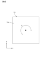
- FIG. 6 is a plan view for explaining the moving direction of the stacking stage moved by the correction mechanism.
- FIG. 3 is a plan view schematically showing the configuration of a support plate.
- FIG. 1 is a plan view schematically showing the configuration of a lamination system including a lamination apparatus in one embodiment.
- FIG. 3 is a diagram schematically showing the configuration of a movable element of a moving mechanism when viewed in a direction along a travel trajectory of a stator.
- FIG. 1 is a side view schematically showing the configuration of a laminating apparatus 100 in one embodiment.
- the laminating apparatus 100 in one embodiment includes a laminating stage 10, a correction mechanism 20, a drive mechanism 30, and a linear motion mechanism 40.
- the stacking stage 10 has a stacking surface 10a, and is a stage for stacking the stacking objects 1 on the stacking surface 10a.
- the stacking stage 10 is made of, for example, ceramic or a metal plate, and preferably made of aluminum, which has high rigidity and is lightweight.
- the shape of the laminated surface 10a can be any shape.
- the shape of the laminated surface 10a when viewed in a direction perpendicular to the laminated surface 10a is rectangular. In FIG. 1, the direction perpendicular to the laminated surface 10a is the Z-axis direction, and the direction parallel to the laminated surface 10a is parallel to the X-axis direction and the Y-axis direction.
- the direction perpendicular to the stacking surface 10a of the stacking stage 10 may be referred to as the Z-axis direction.
- the direction perpendicular to the laminated surface 10a is the vertical direction. Note that any two axes among the X-axis, Y-axis, and Z-axis are in a positional relationship that is orthogonal to each other.
- the stacking objects 1 stacked on the stacking stage 10 have, for example, a sheet-like shape.
- the object to be laminated 1 is not limited to a sheet-like object.
- the stacking objects 1 are sequentially stacked on the stacking surface 10a of the stacking stage 10.
- the stacking objects 1 are stacked on the stacking stage 10 by a holding section that holds the stacking objects 1 .
- the laminating device 100 may include such a holding section.
- the correction mechanism 20 can move the stacking stage 10 in a direction parallel to the stacking surface 10a in order to suppress the displacement of the stacking objects 1 stacked on the stacking surface 10a of the stacking stage 10.
- FIG. 2 is a plan view for explaining the moving direction of the stacking stage 10 moved by the correction mechanism 20.
- the correction mechanism 20 can move the stacking stage 10 in the X-axis direction, the Y-axis direction, and the ⁇ direction, which is the rotation direction around the center of the stacking stage 10. be.
- the correction mechanism 20 is arranged on the side opposite to the lamination surface 10a with respect to the lamination stage 10, and at least a part of which is perpendicular to the lamination surface 10a. It is placed in a position that overlaps with the As shown in FIG. 1, the stacking stage 10 and the correction mechanism 20 are not in direct contact with each other. A space may be provided between the stacking stage 10 and the correction mechanism 20, or another member may be placed between the stacking stage 10 and the correction mechanism 20.
- the linear motion mechanism 40 connects the stacking stage 10 and the correction mechanism 20, and has a degree of freedom of movement in a direction perpendicular to the stacking surface 10a of the stacking stage 10, but cannot move in a direction parallel to the stacking surface 10a. to bound.
- the linear motion mechanism 40 is, for example, a linear shaft. Since the stacking stage 10 and the correction mechanism 20 are connected by the translation mechanism 40, only the stacking stage 10 can be moved independently of the correction mechanism 20 in the direction perpendicular to the stacking surface 10a. It becomes possible.
- the correction mechanism 20 can move the stacking stage 10 with high accuracy in a direction parallel to the stacking surface 10a.
- the correction mechanism 20 includes a UVW stage movable in the X-axis direction, Y-axis direction, and ⁇ direction, and the UVW stage and the lamination stage 10 are connected by a linear motion mechanism 40. Can be done.
- the correction mechanism 20 may be configured to include an XY ⁇ stage including three stages movable in the X-axis direction, Y-axis direction, and ⁇ direction, respectively, instead of one UVW stage.
- the stacking apparatus 100 may include an elastic member 50 that connects the stacking stage 10 and the correction mechanism 20 and applies a force to the stacking stage 10 in a direction toward the correction mechanism 20.
- the elastic member 50 is, for example, a spring. Since the stacking device 100 includes the elastic member 50, the stacking stage 10 is pressed toward the arm portion 32 of the drive mechanism 30, which will be described later. Therefore, as will be described later, when the stacking stage 10 is moved in a direction perpendicular to the stacking surface 10a by the arm portion 32, it can be stably moved.
- the drive mechanism 30 can move the stacking stage 10 in a direction perpendicular to the stacking surface 10a.
- the drive mechanism 30 includes a main body 31 disposed at a position that does not overlap the stacking stage 10 in a direction perpendicular to the stacking surface 10 a of the stacking stage 10 , and a drive mechanism 30 extending from the main body 31 between the stacking stage 10 and the correction mechanism 20 .
- the stacking stage 10 is supported by an arm section 32 configured to be movable in a direction orthogonal to the stacking surface 10a.
- the drive mechanism 30 may further include a motor 35 for moving the arm portion 32 in a direction perpendicular to the stacking surface 10a of the stacking stage 10.
- the main body portion 31 of the drive mechanism 30 has a shape extending in the Z-axis direction.
- One end side of the arm section 32 is attached to the main body section 31 so as to be movable in the Z-axis direction along the main body section 31 having a shape extending in the Z-axis direction, and the other end side is attached to the main body section 31 having a shape extending in the Z-axis direction. It is located between the mechanism 20 and the mechanism 20.
- the arm portion 32 may be connected to the base portion 60 that is not moved by the correction mechanism 20 by the linear motion mechanism 41.
- the linear motion mechanism 41 is, for example, a linear shaft.
- the arm portion 32 is configured to be movable in the Z-axis direction along the main body portion 31, for example, using the same mechanism as a ball screw in which a nut attached to a screw shaft moves along the screw shaft. . That is, the main body portion 31 having a shape extending in the Z-axis direction corresponds to the screw shaft of the ball screw, and the portion of the arm portion 32 that is attached to the main body portion 31 corresponds to the nut of the ball screw.
- the arm portion 32 and the linear motion mechanism 41 are not fixed by the correction mechanism 20 so that the correction mechanism 20 does not change the position. Due to the driving force of the motor 35, the main body portion 31 rotates about a rotation axis parallel to the Z-axis, thereby moving the arm portion 32 in the Z-axis direction.
- the configuration in which the arm portion 32 moves in a direction perpendicular to the stacking surface 10a of the stacking stage 10 is not limited to the above-described configuration.
- the drive mechanism 30 may further include a support plate 33 for supporting the stacking stage 10.
- the support plate 33 is attached to the arm portion 32.
- the support plate 33 has a support surface 33a that is in contact with the stacking stage 10 over a wider area than when the stacking stage 10 is supported only by the arm portion 32. Therefore, by including the support plate 33 in the drive mechanism 30, the lamination stage 10 can be more stably supported by the support plate 33, and the movement of the lamination stage 10 in the direction orthogonal to the lamination surface 10a can be made more stable. can be done.
- FIG. 3 is a plan view schematically showing the configuration of the support plate 33.
- a plurality of slidable materials such as slidable resin 34, are arranged on the support surface 33a of the support plate 33.
- the resin 34 having sliding properties for example, Teflon (registered trademark), ultra-high molecular weight polyethylene, etc. can be used.
- the arm portion 32 of the drive mechanism 30 can move in a direction perpendicular to the stacking surface 10a of the stacking stage 10.
- the support plate 33 attached to the arm portion 32 also moves integrally with the arm portion 32.
- the stacking stage 10 supported by the support plate 33 also moves in a direction perpendicular to the stacking surface 10a. That is, by moving the arm portion 32 of the drive mechanism 30 in a direction perpendicular to the lamination surface 10a, the lamination stage 10 can be moved in a direction perpendicular to the lamination surface 10a.
- the arm portion 32 extends from the main body portion 31 between the lamination stage 10 and the correction mechanism 20 and supports the lamination stage 10, only the lamination stage 10 can be moved in a direction perpendicular to the lamination surface 10a. That is, the correction mechanism 20 does not move due to the movement of the arm portion 32.
- the drive mechanism 30 can move only the laminating stage 10 in the direction perpendicular to the laminating surface 10a, so that the laminating stage 10 and the correction mechanism 20 can be moved together.
- the drive mechanism 30 can be downsized compared to a configuration in which the drive mechanism 30 is configured to For example, if the drive mechanism 30 includes a motor 35 and is configured to move the arm portion 32 by the driving force of the motor 35 to move the stacking stage 10, it is possible to downsize the motor 35. becomes possible.
- the main body 31 of the drive mechanism 30 is arranged at a position that does not overlap with the stacking stage 10 in the direction perpendicular to the stacking surface 10a of the stacking stage 10, compared to a configuration in which it is arranged at a position overlapping with the stacking stage 10, The degree of freedom in design increases.
- the drive mechanism 30 includes a support plate 33 and the support surface 33a of the support plate 33 has sliding properties with respect to the lamination stage 10, the movement of the lamination stage 10 by the correction mechanism 20 and the drive The movement of the stacking stage 10 by the mechanism 30 can be performed in parallel. That is, since the support surface 33a of the support plate 33 has sliding properties with respect to the lamination stage 10, even when the lamination stage 10 is supported by the support plate 33, the correction mechanism 20 allows the lamination stage 10 to be aligned parallel to the lamination surface 10a. It is possible to move in any direction.
- the correction mechanism 20 can move the lamination stage 10 in a direction parallel to the lamination surface 10a, and the drive mechanism 30 can simultaneously move the lamination stage 10 in a direction perpendicular to the lamination surface 10a. , the position of the stacking stage 10 can be corrected in a short time. Thereby, the time required to stack the objects 1 to be stacked on the stacking stage 10 can be shortened.
- FIG. 4 is a plan view schematically showing the configuration of a lamination system 200 including the lamination apparatus 100 in one embodiment.
- Lamination system 200 includes a plurality of supply mechanisms 210 and a movement mechanism 220.
- Lamination system 200 may further include a control unit that controls operations of the plurality of supply mechanisms 210 and movement mechanisms 220.
- the stacking device 100 is included in a moving mechanism 220, as will be described later.
- the stacked object 1 is a sheet-shaped battery material will be described.
- the object to be laminated 1 is not limited to a sheet-like battery material.
- the plurality of supply mechanisms 210 supply the stacked objects 1 to each of the plurality of supply positions A1 to A4.
- One type of stacking object 1 is supplied to each of the plurality of supply positions A1 to A4.
- the plurality of supply mechanisms 210 include four supply mechanisms: a first supply mechanism 210a, a second supply mechanism 210b, a third supply mechanism 210c, and a fourth supply mechanism 210d.
- the number of multiple supply mechanisms 210 is not limited to four.
- the first supply mechanism 210a supplies the stacked objects 1 to the first supply position A1.
- the object to be laminated 1 supplied by the first supply mechanism 210a is, for example, a resin film.
- the resin film is a sheet-shaped battery material that functions as a separator, and is made of polyethylene, for example.
- the first supply mechanism 210a is a belt conveyor, and conveys and supplies the stacked objects 1 placed on the belt to the first supply position A1.
- the second supply mechanism 210b supplies the stacked objects 1 to the second supply position A2.
- the object to be laminated 1 supplied by the second supply mechanism 210b is, for example, a first metal foil.
- the first metal foil is a sheet-shaped battery material that functions as one of the positive electrode and the negative electrode, and is made of, for example, aluminum.
- the second supply mechanism 210b is a belt conveyor, and conveys and supplies the stacked objects 1 placed on the belt to the second supply position A2.
- the third supply mechanism 210c supplies the stacked object 1 to the third supply position A3.
- the object to be laminated 1 supplied by the third supply mechanism 210c is, for example, a resin film.
- the resin film is a sheet-shaped battery material that functions as a separator, and is made of polyethylene, for example.
- the resin film supplied by the third supply mechanism 210c can be the same as the resin film supplied by the first supply mechanism 210a. However, a resin film different from that supplied by the first supply mechanism 210a may be used.
- the third supply mechanism 210c is a belt conveyor, and conveys and supplies the stacked objects 1 placed on the belt to the third supply position A3.
- the fourth supply mechanism 210d supplies the stacked object 1 to the fourth supply position A4.
- the laminated object 1 supplied by the fourth supply mechanism 210d is, for example, a second metal foil.
- the second metal foil is a sheet-shaped battery material that functions as the other electrode of the positive electrode and the negative electrode, and is made of, for example, aluminum.
- the fourth supply mechanism 210d is a belt conveyor, and conveys and supplies the stacked objects 1 placed on the belt to the fourth supply position A4.
- first supply mechanism 210a, the second supply mechanism 210b, the third supply mechanism 210c, and the fourth supply mechanism 210d are not limited to belt conveyors, and may be used to transport the stacked objects 1. Any structure can be used as long as it can be supplied to the supply position.
- the supply mechanism 210 may be configured to transport elongated stacked objects 1 instead of transporting the separated stacked objects 1.
- the long laminated object 1 may be cut into pieces at the supply positions A1 to A4.
- stacking object 1 is rectangular shape, it may be a shape other than a rectangle.
- the moving mechanism 220 includes a stator 221 of a linear motor having a predetermined running track, and a mover 222 of a linear motor that can move between a plurality of supply positions A1 to A4 along the running track.
- the running track of the stator 221 has an elliptical annular shape in plan view, as shown in FIG.
- the shape of the running track in plan view is not limited to an elliptical annular shape.
- the mover 222 includes a first mover 222a, a second mover 222b, a third mover 222c, a fourth mover 222d, a fifth mover 222e, and a sixth mover.
- a child 222f, a seventh mover 222g, and an eighth mover 222h are included.
- Each of the movers 222a to 222h can move independently. Since the moving mechanism 220 includes a plurality of movers 222a to 222h, the stacking objects 1 can be transported and stacked efficiently in a short time.
- FIG. 5 is a diagram schematically showing the configuration of the movable element 222 of the moving mechanism 220 when viewed in the direction along the travel trajectory of the stator 221.
- the movable element 222 includes the laminating device 100 in one embodiment and a holding section 230.
- the X-axis direction is the direction in which the supply mechanism 210 conveys the stacked objects 1
- the Y-axis direction is the direction in which the movable element 222 moves along the traveling track.
- the Z-axis direction is a vertical direction.
- the holding unit 230 holds the stacking object 1 conveyed by the supply mechanism 210.
- the holding part 230 is movable in the Z-axis direction. In this embodiment, the holding unit 230 approaches the stacked object 1 from above by descending, and suctions and holds the stacked object 1 by suction.
- the method by which the holding unit 230 holds the stacked objects 1 is not limited to suction.
- the holding unit 230 holding the stacking object 1 descends toward the stacking stage 10.
- the holding part 230 is lowered by a predetermined amount to release the adsorption of the stacked objects 1.
- the stacking objects 1 are stacked on the stacking stage 10. Since the holding section 230 is configured to descend by a predetermined amount, compared to the case where the amount of descent of the holding section 230 is adjusted according to the number of stacked objects 1 stacked on the stacking stage 10. Therefore, the configuration of the holding section 230 can be simplified.
- stacking target 1 when the stacking target 1 is stacked on the stacking stage 10, "stacking the stacking target 1 on the stacking stage 10" means that the stacking target 1 is stacked on the stacking stage 10. This means that the object 1 to be laminated is laminated.
- the correction mechanism 20 Before the stacking object 1 is stacked on the stacking stage 10 by the holding unit 230, the correction mechanism 20 performs positional deviation correction to move the stacking stage 10 in a direction parallel to the stacking surface 10a, and the drive mechanism 30 , the stacking stage 10 is moved in the Z-axis direction according to the number of stacked objects 1 on the stacking stage 10. A detailed method of positional deviation correction by the correction mechanism 20 will be described later.
- the drive mechanism 30 lowers the stacking stage 10 by the thickness of the stacked stacked objects 1. As a result, even if the holding part 230 holding the stacking object 1 is lowered by a predetermined amount and the stacking object 1 is stacked on the stacking stage 10, the stacking object 1 is lowered on the stacking stage 10. can be stacked in order.
- the movable element 222 is attached to two guide rails 223 of the stator 221 that form a traveling track, and moves along the guide rails 223.
- the guide rail 223 of the stator 221 is provided not vertically below the movable element 222 but on the side thereof.
- control must be performed taking into account the difference in the inner races of the two guide rails 223, but in a structure in which the guide rail 223 is provided on the side, the difference in the inner races must be taken into account. It is not necessary and the control is simple.
- the lamination system 200 in this embodiment further includes an imaging device 240 that images the lamination target 1 supplied by the supply mechanism 210.
- the imaging device 240 is provided vertically above the stacked objects 1 at the supply positions A1 to A4, and images the stacked objects 1 in a stopped state after being supplied to the supply positions A1 to A4 by the supply mechanism 210.
- the imaging device 240 images the stacked object 1 in order to grasp the position and orientation of the stacked object 1. For example, if the rectangular stacked object 1 is imaged by the imaging device 240 and the position of the corner of the stacked object 1 can be determined, the position and orientation of the stacked object 1 can be determined.
- FIG. 5 it appears that a part of the movable element 222 exists on the optical path during imaging by the imaging device 240, but in order to image the stacked object 1 at the supply position, for example, the movable element 222 is A cutout is provided.
- the first imaging device 240a is provided vertically above the first supply position A1
- the second imaging device 240b is provided vertically above the second supply position A2
- the second imaging device 240b is provided vertically above the second supply position A2.
- a third imaging device 240c is provided vertically above A3, and a fourth imaging device 240d is provided vertically above the fourth supply position A4.
- the correction mechanism 20 corrects the relative position of the stacking stage 10 with respect to the stacking target 1 by moving the stacking stage 10 in a direction parallel to the stacking surface 10a based on the image of the stacking target 1 captured by the imaging device 240. Correct the position. Thereby, when stacking the stacking objects 1 on the stacking stage 10, it is possible to obtain a laminate in which displacement of the stacking objects 1 is suppressed.
- the method for correcting the relative position of the stacking stage 10 with respect to the stacking target 1 is not limited to the method based on the image of the stacking target 1.
- the sixth mover 222f has a (3T)/8 delay timing
- the fifth mover 222e has a (4T)/8 delay timing
- the fourth mover 222d has a (5T)/8 delay timing.
- the third movable element 222c performs the same operation as the first movable element 222a at a timing delayed by (6T)/8
- the second movable element 222b operates at a timing delayed by (7T)/8.
- the stacking system 200 includes a control unit that controls the operations of the plurality of supply mechanisms 210 and the plurality of movement mechanisms 220.
- the control unit controls the first supply mechanism 210a so that the resin film, which is the object to be laminated 1, is supplied to the first supply position A1, and also controls the first mover 222a to the first supply position A1. It is stopped at the supply position A1.
- the control unit also controls the first imaging device 240a to image the stacking object 1 stopped at the first supply position A1. After the first imaging device 240a captures the image of the stacked object 1, the control section lowers the holding section 230 to hold the stacked object 1 at the first supply position A1.
- the first movable element 222a is stopped at the first supply position A1
- the third movable element 222c is stopped at the second supply position A2
- the fifth movable element 222c is stopped at the third supply position A3.
- the movable element 222e is stopped
- the seventh movable element 222g is stopped at the fourth supply position A4.
- the third movable element 222c, the fifth movable element 222e, and the seventh movable element 222g each have a laminated layer supplied at each supply position A1 to A4, similarly to the first movable element 222a, as described later.
- the objects 1 are held by the holding section 230 and stacked on the stacking stage 10 while the objects 1 are moved to the next supply positions A1 to A4 and stopped.
- the second movable element 222b is located between the first supply position A1 and the second supply position A2
- the fourth mover 222d is located between the second supply position A2 and the third supply position A3
- the sixth mover 222f is located between the third supply position A3 and the fourth supply position A4.
- the eighth movable element 222h is located between the fourth supply position A4 and the first supply position A1.
- the second movable element 222b, the fourth movable element 222d, the sixth movable element 222f, and the eighth movable element 222h each move to the next supply position A1 to A4 and stop, as will be described later.
- the relative position of the stacking stage 10 with respect to the stacking object 1 is corrected and stacking is performed.
- the control unit moves the first movable element 222a from the first supply position A1 to the second supply position A2 along the traveling track. While the first mover 222a moves from the first supply position A1 to the second supply position A2 and stops, the correction mechanism 20 moves the stacking stage 10 in a direction parallel to the stacking surface 10a. Then, the drive mechanism 30 moves the stacking stage 10 in a direction perpendicular to the stacking surface 10a.
- the correction mechanism 20 moves the stacking stage 10 in a direction parallel to the stacking surface 10a based on the image of the stacked object 1 captured by the first imaging device 240a, thereby adjusting the first
- the relative position of the stacking stage 10 with respect to the stacking object 1 supplied to the supply position A1 is corrected.
- the drive mechanism 30 moves the stacking stage 10 in a direction perpendicular to the stacking surface 10a according to the number of stacked objects 1 stacked on the stacking stage 10.
- the movement of the stacking stage 10 by the correction mechanism 20 and the movement of the stacking stage 10 by the drive mechanism 30 may be performed at the same time, or may be performed at different timings.
- control section lowers the holding section 230 by a predetermined amount, and then causes the holding section 230 to release the stacking object 1 from adsorption. Thereby, the stacking objects 1 are stacked on the stacking stage 10.
- control unit not only moves the first mover 222a from the first supply position A1 to the second supply position A2, but also moves the third mover 222c from the second supply position A2 to the third supply position A2.
- the fifth movable element 222e is moved from the third supply position A3 to the fourth supply position A4, and the seventh movable element 222g is moved from the fourth supply position A4 to the first supply position A4.
- the second movable element 222b, the fourth movable element 222d, the sixth movable element 222f, and the eighth movable element 222h are moved.
- control unit controls the second supply mechanism 210b so that the first metal foil, which is the object to be laminated 1, is supplied to the second supply position A2, and The movable element 222a is stopped at the second supply position A2.
- the control unit also controls the second imaging device 240b to image the stacking object 1 stopped at the second supply position A2. After the second imaging device 240b captures the image of the stacked object 1, the control section lowers the holding section 230 to hold the stacked object 1 at the second supply position A2.
- the third mover 222c is stopped at the third supply position A3, and the fifth mover 222c is stopped at the fourth supply position A4.
- the seventh movable element 222e is stopped, and the seventh movable element 222g is stopped at the first supply position A1.
- the second movable element 222b is located between the second supply position A2 and the third supply position A3, and the fourth movable element 222d is located between the third supply position A3 and the fourth supply position.
- the sixth movable element 222f is located between the fourth supply position A4 and the first supply position A1
- the eighth movable element 222h is located between the fourth supply position A4 and the first supply position A1. and the second supply position A2.
- the control unit moves the first mover 222a from the second supply position A2 to the third supply position A3 along the traveling track. While the first mover 222a moves from the second supply position A2 to the third supply position A3 and stops, the correction mechanism 20 moves the stacking stage 10 in a direction parallel to the stacking surface 10a. , the drive mechanism 30 moves the stacking stage 10 in a direction perpendicular to the stacking surface 10a.
- the correction mechanism 20 moves the stacking stage 10 in a direction parallel to the stacking surface 10a based on the image of the stacking object 1 captured by the second imaging device 240b, thereby adjusting the second
- the relative position of the stacking stage 10 with respect to the stacking target 1 supplied to the supply position A2 is corrected.
- the drive mechanism 30 moves the stacking stage 10 in a direction perpendicular to the stacking surface 10a according to the number of stacked objects 1 stacked on the stacking stage 10. More specifically, the drive mechanism 30 lowers the stacking stage 10 by the thickness of the stacking object 1 newly stacked on the stacking stage 10. After correcting the position of the stacking stage 10, the operation of stacking the stacking objects 1 on the stacking stage 10 is similar to the operation of stacking the stacking objects 1 supplied to the first supply position A1.
- control unit not only moves the first mover 222a from the second supply position A2 to the third supply position A3, but also moves the third mover 222c from the third supply position A3 to the fourth supply position A3.
- the fifth movable element 222e is moved from the fourth supply position A4 to the first supply position A1
- the seventh movable element 222g is moved from the first supply position A1 to the second supply position A1.
- the second movable element 222b, the fourth movable element 222d, the sixth movable element 222f, and the eighth movable element 222h are moved.
- control unit controls the third supply mechanism 210c so that the resin film, which is the object to be laminated 1, is supplied to the third supply position A3, and also controls the first mover 222a. is stopped at the third supply position A3.
- the control unit also controls the third imaging device 240c to image the stacking object 1 stopped at the third supply position A3. After the third imaging device 240c captures the image of the stacked object 1, the control section lowers the holding section 230 to hold the stacked object 1 at the third supply position A3.
- the third movable element 222c is stopped at the fourth supply position A4, and the fifth movable element is stopped at the first supply position A1.
- the seventh movable element 222e is stopped, and the seventh movable element 222g is stopped at the second supply position A2.
- the second movable element 222b is located between the third supply position A3 and the fourth supply position A4, and the fourth movable element 222d is located between the fourth supply position A4 and the first supply position.
- the sixth movable element 222f is located between the first supply position A1 and the second supply position A2
- the eighth movable element 222h is located between the second supply position A2. and the third supply position A3.
- the control unit moves the first movable element 222a from the third supply position A3 to the fourth supply position A4 along the traveling track. While the first mover 222a moves from the third supply position A3 to the fourth supply position A4 and stops, the correction mechanism 20 moves the stacking stage 10 in a direction parallel to the stacking surface 10a. , the drive mechanism 30 moves the stacking stage 10 in a direction perpendicular to the stacking surface 10a.
- the correction mechanism 20 moves the lamination stage 10 in a direction parallel to the lamination surface 10a based on the image of the lamination target 1 captured by the third imaging device 240c, thereby adjusting the third
- the relative position of the stacking stage 10 with respect to the stacking object 1 supplied to the supply position A3 is corrected.
- the drive mechanism 30 moves the stacking stage 10 in a direction perpendicular to the stacking surface 10a according to the number of stacked objects 1 stacked on the stacking stage 10. More specifically, the drive mechanism 30 lowers the stacking stage 10 by the thickness of the stacking object 1 newly stacked on the stacking stage 10. After correcting the position of the stacking stage 10, the operation of stacking the stacking objects 1 on the stacking stage 10 is similar to the operation of stacking the stacking objects 1 supplied to the first supply position A1.
- control unit not only moves the first mover 222a from the third supply position A3 to the fourth supply position A4, but also moves the third mover 222c from the fourth supply position A4 to the first supply position A4.
- the fifth movable element 222e is moved from the first supply position A1 to the second supply position A2, and the seventh movable element 222g is moved from the second supply position A2 to the third supply position A2.
- the second movable element 222b, the fourth movable element 222d, the sixth movable element 222f, and the eighth movable element 222h are moved.
- the control unit controls the fourth supply mechanism 210d so that the second metal foil, which is the object to be laminated 1, is supplied to the fourth supply position A4, and also controls the fourth supply mechanism 210d to The movable element 222a is stopped at the fourth supply position A4. Further, the control unit controls the fourth imaging device 240d to image the stacking object 1 stopped at the fourth supply position A4. After imaging the stacked object 1 by the fourth imaging device 240d, the control section lowers the holding section 230 to hold the stacked object 1 at the fourth supply position A4.
- the third mover 222c is stopped at the first supply position A1
- the fifth mover 222c is stopped at the second supply position A2.
- the movable element 222e is stopped, and the seventh movable element 222g is stopped at the third supply position A3.
- the second movable element 222b is located between the fourth supply position A4 and the first supply position A1
- the fourth movable element 222d is located between the first supply position A1 and the second supply position A1.
- the sixth movable element 222f is located between the second supply position A2 and the third supply position A3
- the eighth movable element 222h is located between the second supply position A2 and the third supply position A3. and the fourth supply position A4.
- the control unit moves the first movable element 222a from the fourth supply position A4 to the first supply position A1 along the traveling track. While the first mover 222a moves from the fourth supply position A4 to the first supply position A1 and stops, the correction mechanism 20 moves the stacking stage 10 in a direction parallel to the stacking surface 10a. , the drive mechanism 30 moves the stacking stage 10 in a direction perpendicular to the stacking surface 10a.
- the correction mechanism 20 moves the stacking stage 10 in a direction parallel to the stacking surface 10a based on the image of the stacked object 1 captured by the fourth imaging device 240d, thereby adjusting the fourth
- the relative position of the stacking stage 10 with respect to the stacking target 1 supplied to the supply position A4 is corrected.
- the drive mechanism 30 moves the stacking stage 10 in a direction perpendicular to the stacking surface 10a according to the number of stacked objects 1 stacked on the stacking stage 10. More specifically, the drive mechanism 30 lowers the stacking stage 10 by the thickness of the stacking object 1 newly stacked on the stacking stage 10. After correcting the position of the stacking stage 10, the operation of stacking the stacking objects 1 on the stacking stage 10 is similar to the operation of stacking the stacking objects 1 supplied to the first supply position A1.
- control unit not only moves the first mover 222a from the fourth supply position A4 to the first supply position A1, but also moves the third mover 222c from the first supply position A1 to the second supply position A1.
- the fifth movable element 222e is moved from the second supply position A2 to the third supply position A3, and the seventh movable element 222g is moved from the third supply position A3 to the fourth supply position A3.
- the second movable element 222b, the fourth movable element 222d, the sixth movable element 222f, and the eighth movable element 222h are moved.
- the laminate is used, for example, as a constituent material of an assembled battery.
- the movable element 222 of the moving mechanism 220 can be downsized, so that the force required to move the movable element 222 can be reduced. can be reduced. Furthermore, the objects 1 to be laminated can be laminated with high accuracy. That is, in the lamination system 200 described above, when a conventional large-scale lamination apparatus is provided instead of the lamination apparatus 100 in one embodiment, the movable element 222 becomes large and a large force is required to move the movable element 222. Is required.
- the movable element 222 repeatedly moves and stops, so as the laminating apparatus becomes larger, the inertia of the movable element 222 increases, causing shaking, and the lamination accuracy of the laminated objects 1 decreases. there is a possibility.
- the laminating apparatus 100 in one embodiment can be miniaturized as described above, the shaking of the movable element 222 can be suppressed, and the laminated objects 1 can be laminated with high accuracy.
- the object to be laminated 1 is not limited to the above-mentioned sheet-shaped battery material.
- the plurality of types of lamination objects 1 are sheet-like conductive layers and insulating layers, and a multilayer substrate can also be produced by laminating the plurality of types of lamination objects 1.
- the conductive layer is made of, for example, copper, silver, an alloy containing copper, an alloy containing silver, or Sn-Ag solder
- the insulating layer is made of, for example, liquid crystal polymer, polyether ether ketone, polyether It is made of thermoplastic resin such as etherimide and polyimide, or thermosetting resin such as epoxy resin and unsaturated polyester.
- the holding section 230 is configured to approach the supply mechanism 210 by descending to hold the stacked object 1, but when the supply mechanism 210 rises, the holding section 230 It may also be configured to approach 230.
- the laminating apparatus and laminating system in this application are as follows. ⁇ 1>. a stacking stage having a stacking surface and stacking objects to be stacked on the stacking surface; a correction mechanism capable of moving the stacking stage in a direction parallel to the stacking surface; a drive mechanism capable of moving the stacking stage in a direction perpendicular to the stacking surface; a linear motion mechanism that connects the stacking stage and the correction mechanism and has a degree of freedom of movement in a direction perpendicular to the stacking surface, but restricts movement in a direction parallel to the stacking surface; Equipped with The driving mechanism includes a main body disposed at a position that does not overlap the laminating stage in a direction perpendicular to the laminating plane, and a main body extending between the laminating stage and the correction mechanism to drive the laminating stage.
- the correction mechanism is arranged at a position opposite to the lamination surface with respect to the lamination stage, at least a part of which overlaps the lamination stage in a direction perpendicular to the lamination surface.
- the drive mechanism further includes a support plate for supporting the stacking stage, The laminating apparatus according to any one of ⁇ 1> to ⁇ 3>, wherein the support plate is attached to the arm portion. ⁇ 5>.
- the laminating apparatus according to ⁇ 4>, wherein the support surface of the support plate in contact with the lamination stage has sliding properties with respect to the lamination stage.
- a plurality of supply mechanisms that supply the stacked objects to each of a plurality of supply positions; a moving mechanism including a stator of a linear motor having a predetermined running track, and a movable element of the linear motor that can move between the plurality of supply positions along the running track; Equipped with A lamination system, wherein the movable element includes the lamination device according to any one of ⁇ 1> to ⁇ 6>. ⁇ 8>.
- Lamination object 10
- Lamination stage 10
- Lamination surface 20
- Correction mechanism 30
- Main body portion 32
- Arm portion 33
- Support plate 33
- Support surface 34
- Motor 19
- Linear motion mechanism 41
- Linear motion mechanism 50
- Elastic member 60
- Base Section 100
- Lamination device 200
- Lamination system 210
- Supply mechanism 220 Movement mechanism 221
- Stator 222 Mover 223
- Guide rail 230
Landscapes
- Engineering & Computer Science (AREA)
- Mechanical Engineering (AREA)
- Container, Conveyance, Adherence, Positioning, Of Wafer (AREA)
- Secondary Cells (AREA)
Priority Applications (3)
| Application Number | Priority Date | Filing Date | Title |
|---|---|---|---|
| CN202380012457.1A CN117597737A (zh) | 2022-06-15 | 2023-02-06 | 层叠装置以及层叠系统 |
| JP2024528278A JP7772215B2 (ja) | 2022-06-15 | 2023-02-06 | 積層装置および積層システム |
| US18/414,028 US20240150148A1 (en) | 2022-06-15 | 2024-01-16 | Stacking apparatus and stacking system |
Applications Claiming Priority (2)
| Application Number | Priority Date | Filing Date | Title |
|---|---|---|---|
| JP2022096220 | 2022-06-15 | ||
| JP2022-096220 | 2022-06-15 |
Related Child Applications (1)
| Application Number | Title | Priority Date | Filing Date |
|---|---|---|---|
| US18/414,028 Continuation US20240150148A1 (en) | 2022-06-15 | 2024-01-16 | Stacking apparatus and stacking system |
Publications (1)
| Publication Number | Publication Date |
|---|---|
| WO2023243135A1 true WO2023243135A1 (ja) | 2023-12-21 |
Family
ID=89192552
Family Applications (1)
| Application Number | Title | Priority Date | Filing Date |
|---|---|---|---|
| PCT/JP2023/003701 Ceased WO2023243135A1 (ja) | 2022-06-15 | 2023-02-06 | 積層装置および積層システム |
Country Status (4)
| Country | Link |
|---|---|
| US (1) | US20240150148A1 (https=) |
| JP (1) | JP7772215B2 (https=) |
| CN (1) | CN117597737A (https=) |
| WO (1) | WO2023243135A1 (https=) |
Citations (7)
| Publication number | Priority date | Publication date | Assignee | Title |
|---|---|---|---|---|
| JPH02238507A (ja) * | 1989-03-13 | 1990-09-20 | Sigma Koki Kk | ステージ移動機構 |
| JPH0397560A (ja) * | 1989-09-12 | 1991-04-23 | Hitachi Ltd | 積層装置 |
| JPH0570255A (ja) * | 1991-09-11 | 1993-03-23 | Nec Corp | アルミナシート積層装置 |
| JP2003028973A (ja) * | 2001-07-13 | 2003-01-29 | Sumitomo Heavy Ind Ltd | ステージ装置 |
| WO2007010971A1 (ja) * | 2005-07-21 | 2007-01-25 | Sumitomo Heavy Industries, Ltd. | ステージ装置 |
| WO2021220771A1 (ja) * | 2020-04-30 | 2021-11-04 | 株式会社村田製作所 | 積層装置 |
| WO2021220770A1 (ja) * | 2020-04-30 | 2021-11-04 | 株式会社村田製作所 | 積層装置 |
Family Cites Families (6)
| Publication number | Priority date | Publication date | Assignee | Title |
|---|---|---|---|---|
| JP2005331402A (ja) * | 2004-05-20 | 2005-12-02 | Sumitomo Heavy Ind Ltd | ステージ装置 |
| JP2007046980A (ja) * | 2005-08-09 | 2007-02-22 | Suruga Seiki Kk | Xyステージ |
| JP5953083B2 (ja) * | 2011-04-07 | 2016-07-13 | 日産自動車株式会社 | 積層装置および積層方法 |
| JP6617440B2 (ja) * | 2015-06-04 | 2019-12-11 | 株式会社豊田自動織機 | 電極積層方法および電極積層装置 |
| JP6819652B2 (ja) * | 2018-06-12 | 2021-01-27 | トヨタ自動車株式会社 | 電池材料積層装置 |
| KR101959082B1 (ko) * | 2018-09-07 | 2019-03-18 | 조기봉 | 이차전지의 셀 스택 고속 제조장치 |
-
2023
- 2023-02-06 JP JP2024528278A patent/JP7772215B2/ja active Active
- 2023-02-06 WO PCT/JP2023/003701 patent/WO2023243135A1/ja not_active Ceased
- 2023-02-06 CN CN202380012457.1A patent/CN117597737A/zh active Pending
-
2024
- 2024-01-16 US US18/414,028 patent/US20240150148A1/en active Pending
Patent Citations (7)
| Publication number | Priority date | Publication date | Assignee | Title |
|---|---|---|---|---|
| JPH02238507A (ja) * | 1989-03-13 | 1990-09-20 | Sigma Koki Kk | ステージ移動機構 |
| JPH0397560A (ja) * | 1989-09-12 | 1991-04-23 | Hitachi Ltd | 積層装置 |
| JPH0570255A (ja) * | 1991-09-11 | 1993-03-23 | Nec Corp | アルミナシート積層装置 |
| JP2003028973A (ja) * | 2001-07-13 | 2003-01-29 | Sumitomo Heavy Ind Ltd | ステージ装置 |
| WO2007010971A1 (ja) * | 2005-07-21 | 2007-01-25 | Sumitomo Heavy Industries, Ltd. | ステージ装置 |
| WO2021220771A1 (ja) * | 2020-04-30 | 2021-11-04 | 株式会社村田製作所 | 積層装置 |
| WO2021220770A1 (ja) * | 2020-04-30 | 2021-11-04 | 株式会社村田製作所 | 積層装置 |
Also Published As
| Publication number | Publication date |
|---|---|
| US20240150148A1 (en) | 2024-05-09 |
| CN117597737A (zh) | 2024-02-23 |
| JPWO2023243135A1 (https=) | 2023-12-21 |
| JP7772215B2 (ja) | 2025-11-18 |
Similar Documents
| Publication | Publication Date | Title |
|---|---|---|
| US12172420B2 (en) | Lamination device | |
| CN111321375B (zh) | 蒸镀装置、电子器件的制造装置以及蒸镀方法 | |
| JP6819652B2 (ja) | 電池材料積層装置 | |
| CN111326461B (zh) | 对准装置、蒸镀装置以及电子器件的制造装置 | |
| KR101917310B1 (ko) | 적층 장치 및 방법 | |
| US11820118B2 (en) | Lamination device | |
| JP5602659B2 (ja) | 極板積載装置 | |
| WO2014087491A1 (ja) | 移載装置 | |
| JP2012056648A (ja) | シート積層装置 | |
| JP6575370B2 (ja) | 電極積層装置 | |
| JP7845313B2 (ja) | 電極積層装置 | |
| CN117293406A (zh) | 一种高速叠片设备、叠片生产线及叠片工艺 | |
| JP2019139961A (ja) | 積層電極体の製造装置 | |
| JP7772215B2 (ja) | 積層装置および積層システム | |
| JP7119410B2 (ja) | 積層電極体の製造装置 | |
| JP2016197527A (ja) | ワーク積層装置 | |
| JP7726403B2 (ja) | 積層装置および積層システム | |
| JP2021104664A (ja) | 積層装置及び積層体の製造方法 | |
| CN115229966B (zh) | 层叠装置以及层叠方法 | |
| KR101411270B1 (ko) | 시트 정렬 이송 장치 | |
| JP2021109752A (ja) | 燃料電池用板状部材の積層装置 | |
| JP2021038056A (ja) | 燃料電池用板状部材の積層装置 | |
| KR20160108736A (ko) | 2단 비전 유닛 세라믹 시트 정렬 이송 시스템 | |
| CN121948116A (zh) | 一种植板机 | |
| JP6347152B2 (ja) | 整列装置 |
Legal Events
| Date | Code | Title | Description |
|---|---|---|---|
| WWE | Wipo information: entry into national phase |
Ref document number: 202380012457.1 Country of ref document: CN |
|
| 121 | Ep: the epo has been informed by wipo that ep was designated in this application |
Ref document number: 23823440 Country of ref document: EP Kind code of ref document: A1 |
|
| WWE | Wipo information: entry into national phase |
Ref document number: 2024528278 Country of ref document: JP |
|
| NENP | Non-entry into the national phase |
Ref country code: DE |
|
| 122 | Ep: pct application non-entry in european phase |
Ref document number: 23823440 Country of ref document: EP Kind code of ref document: A1 |