WO2023233503A1 - 二酸化炭素回収装置、および二酸化炭素回収方法 - Google Patents
二酸化炭素回収装置、および二酸化炭素回収方法 Download PDFInfo
- Publication number
- WO2023233503A1 WO2023233503A1 PCT/JP2022/022048 JP2022022048W WO2023233503A1 WO 2023233503 A1 WO2023233503 A1 WO 2023233503A1 JP 2022022048 W JP2022022048 W JP 2022022048W WO 2023233503 A1 WO2023233503 A1 WO 2023233503A1
- Authority
- WO
- WIPO (PCT)
- Prior art keywords
- carbon dioxide
- air
- adsorbent
- duct
- flow path
- Prior art date
- Legal status (The legal status is an assumption and is not a legal conclusion. Google has not performed a legal analysis and makes no representation as to the accuracy of the status listed.)
- Ceased
Links
Images






Classifications
-
- F—MECHANICAL ENGINEERING; LIGHTING; HEATING; WEAPONS; BLASTING
- F24—HEATING; RANGES; VENTILATING
- F24F—AIR-CONDITIONING; AIR-HUMIDIFICATION; VENTILATION; USE OF AIR CURRENTS FOR SCREENING
- F24F8/00—Treatment, e.g. purification, of air supplied to human living or working spaces otherwise than by heating, cooling, humidifying or drying
- F24F8/10—Treatment, e.g. purification, of air supplied to human living or working spaces otherwise than by heating, cooling, humidifying or drying by separation, e.g. by filtering
-
- B—PERFORMING OPERATIONS; TRANSPORTING
- B01—PHYSICAL OR CHEMICAL PROCESSES OR APPARATUS IN GENERAL
- B01D—SEPARATION
- B01D53/00—Separation of gases or vapours; Recovering vapours of volatile solvents from gases; Chemical or biological purification of waste gases, e.g. engine exhaust gases, smoke, fumes, flue gases, aerosols
- B01D53/02—Separation of gases or vapours; Recovering vapours of volatile solvents from gases; Chemical or biological purification of waste gases, e.g. engine exhaust gases, smoke, fumes, flue gases, aerosols by adsorption, e.g. preparative gas chromatography
- B01D53/04—Separation of gases or vapours; Recovering vapours of volatile solvents from gases; Chemical or biological purification of waste gases, e.g. engine exhaust gases, smoke, fumes, flue gases, aerosols by adsorption, e.g. preparative gas chromatography with stationary adsorbents
- B01D53/0407—Constructional details of adsorbing systems
- B01D53/0438—Cooling or heating systems
-
- B—PERFORMING OPERATIONS; TRANSPORTING
- B01—PHYSICAL OR CHEMICAL PROCESSES OR APPARATUS IN GENERAL
- B01D—SEPARATION
- B01D53/00—Separation of gases or vapours; Recovering vapours of volatile solvents from gases; Chemical or biological purification of waste gases, e.g. engine exhaust gases, smoke, fumes, flue gases, aerosols
- B01D53/02—Separation of gases or vapours; Recovering vapours of volatile solvents from gases; Chemical or biological purification of waste gases, e.g. engine exhaust gases, smoke, fumes, flue gases, aerosols by adsorption, e.g. preparative gas chromatography
- B01D53/04—Separation of gases or vapours; Recovering vapours of volatile solvents from gases; Chemical or biological purification of waste gases, e.g. engine exhaust gases, smoke, fumes, flue gases, aerosols by adsorption, e.g. preparative gas chromatography with stationary adsorbents
- B01D53/0462—Temperature swing adsorption
-
- B—PERFORMING OPERATIONS; TRANSPORTING
- B01—PHYSICAL OR CHEMICAL PROCESSES OR APPARATUS IN GENERAL
- B01D—SEPARATION
- B01D2257/00—Components to be removed
- B01D2257/50—Carbon oxides
- B01D2257/504—Carbon dioxide
-
- B—PERFORMING OPERATIONS; TRANSPORTING
- B01—PHYSICAL OR CHEMICAL PROCESSES OR APPARATUS IN GENERAL
- B01D—SEPARATION
- B01D2258/00—Sources of waste gases
- B01D2258/06—Polluted air
-
- B—PERFORMING OPERATIONS; TRANSPORTING
- B01—PHYSICAL OR CHEMICAL PROCESSES OR APPARATUS IN GENERAL
- B01D—SEPARATION
- B01D2259/00—Type of treatment
- B01D2259/45—Gas separation or purification devices adapted for specific applications
- B01D2259/4508—Gas separation or purification devices adapted for specific applications for cleaning air in buildings
-
- F—MECHANICAL ENGINEERING; LIGHTING; HEATING; WEAPONS; BLASTING
- F24—HEATING; RANGES; VENTILATING
- F24F—AIR-CONDITIONING; AIR-HUMIDIFICATION; VENTILATION; USE OF AIR CURRENTS FOR SCREENING
- F24F2110/00—Control inputs relating to air properties
- F24F2110/50—Air quality properties
- F24F2110/65—Concentration of specific substances or contaminants
- F24F2110/70—Carbon dioxide
-
- F—MECHANICAL ENGINEERING; LIGHTING; HEATING; WEAPONS; BLASTING
- F24—HEATING; RANGES; VENTILATING
- F24F—AIR-CONDITIONING; AIR-HUMIDIFICATION; VENTILATION; USE OF AIR CURRENTS FOR SCREENING
- F24F7/00—Ventilation
- F24F7/04—Ventilation with ducting systems, e.g. by double walls; with natural circulation
- F24F7/06—Ventilation with ducting systems, e.g. by double walls; with natural circulation with forced air circulation, e.g. by fan positioning of a ventilator in or against a conduit
- F24F7/08—Ventilation with ducting systems, e.g. by double walls; with natural circulation with forced air circulation, e.g. by fan positioning of a ventilator in or against a conduit with separate ducts for supplied and exhausted air with provisions for reversal of the input and output systems
-
- Y—GENERAL TAGGING OF NEW TECHNOLOGICAL DEVELOPMENTS; GENERAL TAGGING OF CROSS-SECTIONAL TECHNOLOGIES SPANNING OVER SEVERAL SECTIONS OF THE IPC; TECHNICAL SUBJECTS COVERED BY FORMER USPC CROSS-REFERENCE ART COLLECTIONS [XRACs] AND DIGESTS
- Y02—TECHNOLOGIES OR APPLICATIONS FOR MITIGATION OR ADAPTATION AGAINST CLIMATE CHANGE
- Y02C—CAPTURE, STORAGE, SEQUESTRATION OR DISPOSAL OF GREENHOUSE GASES [GHG]
- Y02C20/00—Capture or disposal of greenhouse gases
- Y02C20/40—Capture or disposal of greenhouse gases of CO2
Definitions
- the present disclosure relates to a carbon dioxide recovery device and a carbon dioxide recovery method.
- Patent Document 1 discloses an apparatus that removes carbon dioxide from the air using an adsorbent that can adsorb carbon dioxide.
- the present disclosure aims to provide a carbon dioxide recovery device and a carbon dioxide recovery method that can improve carbon dioxide recovery efficiency.
- One aspect of the carbon dioxide recovery device includes a blower that is provided in an air flow path that circulates air between indoors and outdoors, and that forms an air flow in the air flow path; an inflow duct that allows air to flow in, an outflow duct that causes air to flow out from the air flow path, and an adsorbent that adsorbs carbon dioxide in the air, and at least one of the inflow duct and the outflow duct.
- an adsorption area is provided in which the adsorbent adsorbs carbon dioxide contained in the air.
- One aspect of the carbon dioxide recovery method includes: a blower that is provided in an air flow path that circulates air between indoors and outdoors, and that forms an air flow in the air flow path; Carbon dioxide is recovered using a carbon dioxide recovery device that includes an inflow duct that allows air to flow into the air flow path, an outflow duct that causes air to flow out from the air flow path, and an adsorbent that adsorbs carbon dioxide in the air.
- the recovery method includes an adsorption step of bringing the adsorbent into contact with air to adsorb carbon dioxide onto the adsorbent in an adsorption area provided in at least one of the inflow duct and the outflow duct. In the adsorption step, the air blower forms an air flow in the air flow path to circulate air in the adsorption area.
- Another aspect of the carbon dioxide recovery method is a carbon dioxide recovery method including an air supply flow path and an exhaust flow path, and an intake blower provided in the air supply flow path and an exhaust blower provided in the exhaust flow path.
- a heat exchanger a first inflow duct that causes air to flow into the air supply flow path, a first outflow duct that causes air to flow out from the air supply flow path, and a second inflow duct that causes air to flow into the exhaust flow path;
- a carbon dioxide recovery method for recovering carbon dioxide using a carbon dioxide recovery device including a second outflow duct that causes air to flow out from the exhaust flow path, and an adsorbent that adsorbs carbon dioxide in the air the method comprising: an adsorption step of bringing the adsorbent into contact with air to adsorb carbon dioxide onto the adsorbent in an adsorption area provided in at least one of the first inflow duct and the second inflow duct; In the step, the intake blower or the exhaust blower forms an
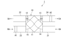
- FIG. 1 is a schematic diagram showing a carbon dioxide recovery device according to Embodiment 1.
- FIG. FIG. 3 is a schematic diagram showing a carbon dioxide recovery device according to a modification of the first embodiment.
- FIG. 2 is a schematic diagram showing a carbon dioxide recovery device according to a second embodiment.
- FIG. 7 is a schematic diagram showing a carbon dioxide recovery device according to a modification of the second embodiment.
- FIG. 3 is a schematic diagram showing a carbon dioxide recovery device according to Embodiment 3.
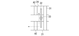
- FIG. 7 is a diagram illustrating an adsorption step in the carbon dioxide recovery device according to Embodiment 3.
- 7 is a diagram illustrating a separation process in the carbon dioxide recovery device according to Embodiment 3.
- FIG. 7 is a diagram illustrating a separation process in a carbon dioxide recovery device according to a modification of Embodiment 3.
- FIG. 3 is a schematic diagram showing a carbon dioxide recovery device according to a fourth embodiment.
- FIG. 7 is a schematic diagram showing a carbon dioxide recovery device according to a fifth embodiment.
- FIG. 7 is a schematic diagram showing a carbon dioxide recovery device according to a sixth embodiment.
- FIG. 7 is a schematic diagram showing a carbon dioxide recovery device according to a modification of the sixth embodiment.
- FIG. 7 is a block diagram showing a carbon dioxide recovery system according to a seventh embodiment.
- FIG. 7 is a perspective view showing a carbon dioxide recovery system according to an eighth embodiment.
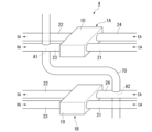
- FIG. 1 is a schematic diagram showing a carbon dioxide recovery apparatus 1 according to the first embodiment.
- the carbon dioxide recovery apparatus 1 includes an adsorbent, a stationary total heat exchanger 10 (hereinafter also simply referred to as "total heat exchanger 10"), a first inflow duct 21, and a first inflow duct 21. It includes a first outflow duct 22, a second inflow duct 23, and a second outflow duct 24.
- the total heat exchanger 10 includes a total heat exchange element 11, an intake blower 12, and an exhaust blower 13. Further, the total heat exchanger 10 is formed with an air supply channel 14 that supplies air from the outdoors into the room, and an exhaust channel 15 that discharges air from the room to the outdoors.
- the air supply flow path 14 and the exhaust flow path 15 are examples of air flow paths.
- a part of the air supply flow path 14 and a part of the exhaust flow path 15 are formed in the total heat exchange element 11.
- the total heat exchange element 11 performs heat exchange between the air flowing through the supply air flow path 14 and the air flowing through the exhaust flow path 15.
- the intake blower 12 is installed in the air supply flow path 14 .
- the intake blower 12 forms a flow of air from outdoors to indoors.
- the exhaust blower 13 is installed in the exhaust flow path 15.
- the exhaust blower 13 forms a flow of air from indoors to outdoors.
- the intake blower 12 and the exhaust blower 13 are examples of blowers.
- the first inflow duct 21 allows air to flow into the air supply flow path 14 .
- the first outflow duct 22 allows air to flow out from the air supply channel 14 .
- the second inflow duct 23 allows air to flow into the exhaust flow path 15.
- the second outflow duct 24 allows air to flow out from the exhaust flow path 15.
- the first inflow duct 21, the first outflow duct 22, the second inflow duct 23, and the second outflow duct 24 are arranged inside the building, for example, under the ceiling.
- outdoor air By driving the intake blower 12 , outdoor air (OA) flows into the air supply flow path 14 via the first inflow duct 21 . Outdoor air passes through the air supply flow path 14 and is supplied indoors from the first outflow duct 22 as supply air (SA).
- SA supply air
- RA return air
- SA exhaust air
- EA exhaust air
- the adsorbent contains a material that can adsorb carbon dioxide.
- materials capable of adsorbing carbon dioxide include amines, zeolites, silica gel, diatomaceous earth, alumina, and activated carbon. A plurality of materials may be selected from those listed above, or materials other than those listed above may be employed.
- the adsorbent may be granular (eg, bead-like (spherical), pellet-like (cylindrical)).
- a powdered adsorbent may be employed. In this case, a powdered adsorbent may be supported on the surface of the base material.
- the base material may have a honeycomb shape, for example.
- the second inflow duct 23 is provided with an adsorption area A1 that causes an adsorbent to adsorb carbon dioxide contained in the air.
- the adsorbent is placed in the adsorption area A1.
- the adsorbent may be flowed into the adsorption area A1 from an adsorbent transport duct (not shown) that intersects the second inflow duct 23.
- the carbon dioxide recovery method includes an adsorption step.
- air containing carbon dioxide is brought into contact with an adsorbent in the adsorption area A1, so that the adsorbent adsorbs carbon dioxide.
- the exhaust blower 13 forms a flow of air from the indoor to the outdoor in the exhaust flow path 15, and circulates the air to the adsorption area A1 (ie, the second inflow duct 23). Thereby, carbon dioxide is recovered from the air flowing through the adsorption area A1.
- the carbon dioxide recovery device 1 includes the exhaust blower 13 that is provided in the exhaust flow path 15 and forms the flow of air in the exhaust flow path 15, and the exhaust blower 13 that is provided in the exhaust flow path 15 to form an air flow in the exhaust flow path 15. It includes a second inflow duct 23 that causes air to flow in, a second outflow duct 24 that causes air to flow out from the exhaust flow path 15, and an adsorbent that adsorbs carbon dioxide in the air.
- the second inflow duct 23 is provided with an adsorption area A1 in which carbon dioxide contained in the air is adsorbed by an adsorbent.
- the carbon dioxide recovery method brings air into contact with an adsorbent that adsorbs carbon dioxide in the adsorption area A1 provided in the second inflow duct 23 that causes air to flow into the exhaust flow path 15,
- the method includes an adsorption step of adsorbing carbon dioxide onto an adsorbent.
- an air flow is formed in the exhaust flow path 15 by the exhaust blower 13 provided in the exhaust flow path 15, and the air is distributed to the adsorption area A1.
- the suction area A1 is provided in the second inflow duct 23.
- the carbon dioxide concentration in indoor air often increases as people breathe. Indoor air with a high carbon dioxide concentration flows into the second inflow duct 23 .
- carbon dioxide can be recovered from air with a high carbon dioxide concentration, and it is possible to further improve the carbon dioxide recovery efficiency. Furthermore, since the air flowing into the second inflow duct 23 is not affected by changes in the humidity of the outside air and has stable humidity, the carbon dioxide adsorption performance of the adsorbent does not deteriorate and the carbon dioxide is stabilized. and can be recovered.
- FIG. 2 is a schematic diagram showing a carbon dioxide recovery apparatus 1 according to a modification of the first embodiment.
- the suction area A1 is provided in the first inflow duct 21.
- air containing carbon dioxide is brought into contact with an adsorbent in the adsorption area A1, so that the adsorbent adsorbs carbon dioxide.
- the intake blower 12 forms a flow of air from the outdoors to the indoors in the air supply channel 14, and causes the air to flow into the suction area A1 (that is, the first inflow duct 21).
- the carbon dioxide recovery device 1 includes an intake blower 12 that is provided in the air supply passage 14 and forms the flow of air in the air supply passage 14, and a first inflow duct 21 that causes air to flow into the air supply passage 14. , a first outflow duct 22 that causes air to flow out from the air supply channel 14, and an adsorbent that adsorbs carbon dioxide in the air.
- the first inflow duct 21 is provided with an adsorption area A1 in which carbon dioxide contained in the air is adsorbed by an adsorbent.
- the carbon dioxide recovery method includes an adsorption step of adsorbing carbon onto an adsorbent.
- the air flow in the air supply flow path 14 is formed by the intake blower 12 provided in the air supply flow path 14, and the air is distributed to the suction area A1.
- air is caused to flow through the adsorption area A1 provided in the first inflow duct 21, and carbon dioxide contained in the air is adsorbed by the adsorbent. Since carbon dioxide can be directly recovered from the air flowing through the first inflow duct 21, the carbon dioxide recovery efficiency can be improved.
- Embodiment 2 Next, a carbon dioxide recovery device 1 and a carbon dioxide recovery method according to a second embodiment will be described. Since the basic configuration of the carbon dioxide recovery apparatus 1 according to the present embodiment is the same as that of the first embodiment, the explanation will focus on the different points.
- FIG. 3 is a schematic diagram showing the carbon dioxide recovery device 1 according to the second embodiment.
- the second outflow duct 24 is provided with a separation area A2 that separates carbon dioxide from the adsorbent that has adsorbed carbon dioxide.
- the adsorbent that has adsorbed carbon dioxide in the adsorption area A1 of the second inflow duct 23 is transported to the separation area A2 of the second outflow duct 24.
- the adsorbent may be transported from the adsorption area A1 to the separation area A2 using a transport duct (not shown) that connects the second inflow duct 23 and the second outflow duct 24.
- the adsorbent transported from the adsorption area A1 is placed in the separation area A2.
- the separation area A2 For example, by fixing a breathable container to the inner wall of the second outflow duct 24 and accommodating the adsorbent in this container, the adsorbent adsorbing carbon dioxide is placed in the separation area A2.
- the adsorbent may be flowed into the separation area A2 from an adsorbent transport duct (not shown) that intersects the second outflow duct 24.
- carbon dioxide is separated by heating the adsorbent that has adsorbed carbon dioxide.
- the heating temperature is, for example, 120 to 160°C.
- the heating temperature may be changed as appropriate depending on the specific material of the adsorbent.
- the carbon dioxide recovery method includes an adsorption step and a separation step. Since the adsorption step is the same as in Embodiment 1, the description thereof will be omitted here.
- the separation step carbon dioxide is separated from the adsorbent that has adsorbed carbon dioxide in the adsorption step by heating the adsorbent that has adsorbed carbon dioxide in the separation area A2.
- the total heat exchange element 11 performs heat exchange between the air flowing through the supply air flow path 14 and the air flowing through the exhaust flow path 15.
- the heat contained in the air flowing in from the first inflow duct 21 and flowing through the air supply flow path 14 is transferred to the exhaust flow path 15 by heat exchange by the total heat exchange element 11. transmitted to the circulating air. That is, the heat contained in the air flowing in from the first inflow duct 21 is conveyed to the separation area A2 of the second outflow duct 24 by the total heat exchange element 11. Therefore, the heat contained in the air flowing in from the first inflow duct 21 can be used for the separation process.
- a heater (not shown) may be provided in the second outflow duct 24 on the upstream side of the separation area A2 in the air flow direction.
- a heater By heating the air flowing through the separation area A2 with the heater, carbon dioxide can be more effectively separated from the adsorbent. Even in this case, by using the adsorption heat and the heat contained in the air flowing in from the first inflow duct 21 in the separation process, the heating energy by the heater can be suppressed, and energy saving can be achieved. can.
- the second outflow duct 24 is provided with a separation area A2 that separates carbon dioxide from the adsorbent that has adsorbed carbon dioxide.
- the carbon dioxide recovery method further includes a separation step of separating carbon dioxide from the adsorbent that has adsorbed carbon dioxide in the separation area A2 provided in the second outflow duct 24.
- a separation step carbon dioxide is separated from the adsorbent using the heat of adsorption when the adsorbent adsorbs carbon dioxide in the adsorption step and the heat contained in the air flowing in from the first inflow duct 21.
- the heat of adsorption when the adsorbent adsorbs carbon dioxide in the adsorption area A1 and the heat contained in the air flowing in from the first inflow duct 21 are transported to the separation area A2 and used to separate carbon dioxide from the adsorbent. be able to. Therefore, for example, it is not necessary to heat the air with a heater to separate carbon dioxide, or the heating energy of the heater can be suppressed, resulting in energy savings and improving the carbon dioxide recovery efficiency of the entire device. be able to.
- FIG. 4 is a schematic diagram showing a carbon dioxide recovery device 1 according to a modification of the second embodiment.
- the adsorption area A1 is provided in the first inflow duct 21, and the separation area A2 is provided in the second outflow duct 24. That is, the suction process is performed in the suction area A1 of the first inflow duct 21.
- the adsorbent that has adsorbed carbon dioxide in the adsorption area A1 of the first inflow duct 21 is transported to the separation area A2 of the second outflow duct 24.
- a separation process is performed in the separation area A2 of the second outflow duct 24.
- the heat of adsorption when the adsorbent adsorbs carbon dioxide in the adsorption area A1 of the first inflow duct 21 and the heat contained in the air flowing in from the first inflow duct 21 are transferred to the second outflow duct by the total heat exchange element 11. It is transported to separation area A2 of No. 24. Therefore, the heat of adsorption when the adsorbent adsorbs carbon dioxide and the heat contained in the air flowing in from the first inflow duct 21 can be used for the separation process.
- Embodiment 3 Next, a carbon dioxide recovery device 1 and a carbon dioxide recovery method according to Embodiment 3 will be described. Since the basic configuration of the carbon dioxide recovery apparatus 1 according to the present embodiment is the same as that of the first and second embodiments, the explanation will focus on the different points.
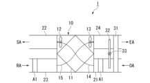
- FIG. 5 is a schematic diagram showing the carbon dioxide recovery device 1 according to the third embodiment.
- the carbon dioxide recovery apparatus 1 includes an adsorbent, a total heat exchanger 10, a first inflow duct 21, a first outflow duct 22, and a second inflow duct. 23, a second outflow duct 24, a dehumidifier 31, a heat exchanger 32, and a switching section 33. Further, the suction area A1 is provided in the first inflow duct 21.
- the dehumidifying material 31 is formed into a disk shape centered on the rotating shaft 31a.
- the dehumidifying material 31 is rotatable around a rotating shaft 31a.
- the dehumidifying material 31 is provided so as to straddle the first inflow duct 21 and the second outflow duct 24 .
- the dehumidifying material 31 is arranged upstream of the adsorption area A1 in the air flow direction.
- the dehumidifying material 31 absorbs moisture in the air flowing through the first inflow duct 21. Air whose moisture has been absorbed by the dehumidifying material 31 flows through the adsorption area A1.
- the portion of the dehumidifying material 31 that has been placed in the first inflow duct 21 and has absorbed moisture is moved to the second outflow duct 24, and the portion of the dehumidification material 31 that is placed in the first inflow duct 21 and has absorbed moisture is moved to the second outflow duct 24, and the part of the dehumidification material 31 that is placed in the first inflow duct 21 and has absorbed moisture is moved to the second outflow duct 24.
- the heat exchanger 32 performs heat exchange between the air flowing between the adsorption area A1 and the dehumidifying material 31 in the first inflow duct 21 and the air flowing through the second outflow duct 24.
- the heat exchanger 32 is arranged between the adsorption area A1 and the dehumidifying material 31.
- the switching unit 33 is configured to transfer heat from the first inflow duct 21 to the second outflow duct 24 by the heat exchanger 32 and to transfer heat from the second outflow duct 24 to the first inflow duct 21 by the heat exchanger 32. A state in which heat is transferred and a state in which heat is not transferred between the first inflow duct 21 and the second outflow duct 24 are switched.
- the carbon dioxide recovery method includes an adsorption step and a separation step.
- the adsorption process will be explained with reference to FIG. 6A.
- air containing carbon dioxide is brought into contact with an adsorbent in the adsorption area A1, so that the adsorbent adsorbs carbon dioxide.
- the moisture in the air flowing through the first inflow duct 21 is absorbed by the dehumidifying material 31, so that dehumidified air flows into the adsorption area A1.
- the adsorption efficiency of carbon dioxide by the adsorbent may decrease.
- the dehumidifying material 31 absorbs moisture in the air, heat is generated.
- the switching unit 33 switches the heat exchanger 32 to a state in which heat is transferred from the first inflow duct 21 to the second outflow duct 24 .
- the heat generated in the dehumidifying material 31 is transferred (released) to the second outflow duct 24, as shown by the dotted arrow in FIG. 6A.
- the temperature of the air in contact with the adsorbent is high, the adsorption efficiency of carbon dioxide by the adsorbent may decrease.
- a separation step is performed to separate carbon dioxide from the adsorbent that has adsorbed carbon dioxide. That is, both the adsorption area A1 and the separation area A2 are provided in the first inflow duct 21.
- the adsorption step will be explained with reference to FIG. 6B.
- carbon dioxide is separated from the adsorbent that has adsorbed carbon dioxide in the adsorption step by heating the adsorbent that has adsorbed carbon dioxide in the separation area A2.
- the switching unit 33 switches to a state in which heat is not transferred between the first inflow duct 21 and the second outflow duct 24.
- the heat generated in the dehumidifying material 31 is not transmitted to the second outflow duct 24, but is transported to the separation area A2. Therefore, the heat generated by the dehumidifying material 31 can be used for the separation process.
- the adsorption area A1 is provided in the first inflow duct 21.
- the carbon dioxide recovery device 1 includes a dehumidifying material 31 provided upstream of the adsorption area A1 in the direction of air flow in the first inflow duct 21.
- dehumidifying material 31 By absorbing moisture in the air flowing through the first inflow duct 21 by the dehumidifying material 31, dehumidified air flows through the adsorption area A1. Therefore, the adsorption efficiency of carbon dioxide in the adsorption area A1 can be improved.
- the carbon dioxide recovery device 1 also includes heat exchange between the air flowing between the adsorption area A1 and the dehumidifying material 31 in the first inflow duct 21 and the air flowing through the second outflow duct 24.
- the heat exchanger 32 is configured to transfer heat from the first inflow duct 21 to the second outflow duct 24 by the heat exchanger 32, and to transfer heat from the second outflow duct 24 to the first inflow duct 21 by the heat exchanger 32. It includes a switching unit 33 that switches between a state where heat is transferred and a state where heat is not transferred between the first inflow duct 21 and the second outflow duct 24.
- the switching unit 33 switches the heat exchanger 32 to a state in which heat is transferred from the first inflow duct 21 to the second outflow duct 24.
- heat generated when moisture in the air is absorbed by the dehumidifying material 31 can be transmitted (released) to the second outflow duct 24. Therefore, it is possible to prevent the carbon dioxide adsorption efficiency from decreasing due to the heat generated by the dehumidifying material 31.
- the switching unit 33 by switching the switching unit 33 to a state in which heat is not transferred between the first inflow duct 21 and the second outflow duct 24, the heat generated in the dehumidifying material 31 is used to Carbon dioxide can also be separated from an adsorbent that has adsorbed carbon dioxide.
- FIG. 7 is a schematic diagram showing a carbon dioxide recovery device 1 according to a modification of the third embodiment.
- a separation process for separating carbon dioxide from the adsorbent is performed at two locations, the first inflow duct 21 and the second outflow duct 24. That is, the separation area A2 is provided in the first inflow duct 21 and the second outflow duct 24.
- the switching unit 33 switches a part of the heat generated by the dehumidifying material 31 to be transferred from the first inflow duct 21 to the second outflow duct 24 using the heat exchanger 32.
- the separation step can be performed at two locations, so that the carbon dioxide recovery efficiency can be further improved.
- Embodiment 4 Next, a carbon dioxide recovery device 1 and a carbon dioxide recovery method according to Embodiment 4 will be described.
- the basic configuration of the carbon dioxide recovery device 1 according to this embodiment is the same as that of the third embodiment, so the explanation will focus on the different points.
- FIG. 8 is a schematic diagram showing the carbon dioxide recovery device 1 according to the fourth embodiment.
- the adsorption process is performed in both the first inflow duct 21 and the second inflow duct 23. That is, the suction area A1 is provided in the first inflow duct 21 and the second inflow duct 23.
- carbon dioxide can be recovered from both the air flowing through the first inflow duct 21 and the air flowing through the second inflow duct 23, increasing the amount of carbon dioxide recovered. Efficiency can be further improved.
- the second outflow duct 24 may be provided with a separation area A2 that separates carbon dioxide from the adsorbent that has adsorbed carbon dioxide.
- the adsorbent that has adsorbed carbon dioxide in the adsorption area A1 of the first inflow duct 21 or the second inflow duct 23 is transported to the separation area A2 of the second outflow duct 24.
- separation area A2 carbon dioxide is separated by heating the adsorbent that has adsorbed carbon dioxide.
- Embodiment 5 Next, a carbon dioxide recovery device 1 and a carbon dioxide recovery method according to Embodiment 5 will be described.
- the basic configuration of the carbon dioxide recovery apparatus 1 according to the present embodiment is the same as that of the fourth embodiment, so the explanation will focus on the different points.
- FIG. 9 is a schematic diagram showing a carbon dioxide recovery device 1 according to the fifth embodiment.
- the adsorption process is performed in the second inflow duct 23, and the separation process is performed in the first inflow duct 21. That is, the adsorption area A1 is provided in the second inflow duct 23, and the separation area A2 is provided in the first inflow duct 21.
- the switching unit 33 switches to a state in which the heat exchanger 32 transfers heat from the second outflow duct 24 to the first inflow duct 21.
- the adsorption heat in the adsorption area A1 of the second inflow duct 23 is conveyed to the second outflow duct 24 through the exhaust flow path 15.
- the heat of adsorption transferred to the second outflow duct 24 is transferred to the first inflow duct 21 by the heat exchanger 32. Therefore, the adsorption heat in the adsorption area A1 of the second inflow duct 23 can be used for the separation process in the separation area A2 of the first inflow duct 21.
- FIG. 10 is a schematic diagram showing a carbon dioxide recovery device 2 according to the sixth embodiment.
- the carbon dioxide recovery device 2 according to the sixth embodiment includes an adsorbent, an exhaust ventilation fan 41, an inflow duct 42, and an outflow duct 43. Note that the structure of the adsorbent is the same as that in Embodiment 1, so its description is omitted here.
- the exhaust ventilation fan 41 is provided in an exhaust flow path 44 that exhausts air from indoors to outdoors.
- the exhaust ventilation fan 41 forms a flow of air from indoors to outdoors.
- the exhaust ventilation fan 41 is an example of a blower.
- the exhaust flow path 44 is an example of an air flow path.
- the inflow duct 42 allows air to flow into the exhaust flow path 44 .
- the inflow duct 42 is arranged on the indoor side of the exhaust flow path 44.
- Outflow duct 43 allows air to flow out from exhaust flow path 44 .
- the outflow duct 43 is arranged on the outdoor side of the exhaust flow path 44.
- the inflow duct 42 is provided with an adsorption area A1 that causes an adsorbent to adsorb carbon dioxide contained in the air. That is, the adsorbent is placed in the adsorption area A1.
- the adsorbent is arranged in the adsorption area A1.
- the adsorbent may be flowed into the adsorption area A1 from an adsorbent transport duct (not shown) that intersects the inflow duct 42.
- the carbon dioxide recovery method includes an adsorption step.
- air containing carbon dioxide is brought into contact with an adsorbent in the adsorption area A1, so that the adsorbent adsorbs carbon dioxide.
- the exhaust ventilation fan 41 forms a flow of air from the indoor to the outdoor in the exhaust flow path 44, and the air is distributed to the adsorption area A1 (that is, the inflow duct 42). Thereby, carbon dioxide is recovered from the air flowing through the adsorption area A1.
- the carbon dioxide recovery device 2 includes the exhaust ventilation fan 41 that is provided in the exhaust flow path 44 and forms the air flow in the exhaust flow path 44, and the exhaust ventilation fan 41 that is provided in the exhaust flow path 44 to form an air flow in the exhaust flow path 44.
- An inflow duct 42 that allows air to flow in, an outflow duct 43 that causes air to flow out from an exhaust flow path 44, and an adsorbent that adsorbs carbon dioxide in the air.
- the inflow duct 42 is provided with an adsorption area A1 that causes an adsorbent to adsorb carbon dioxide contained in the air.
- the carbon dioxide recovery method in the adsorption area A1 provided in the inflow duct 42 that causes air to flow into the exhaust flow path 44, air is brought into contact with an adsorbent that adsorbs carbon dioxide. an adsorption step of causing the adsorbent to adsorb the adsorbent. In the adsorption step, an air flow is formed in the exhaust flow path 44 by the exhaust ventilation fan 41 provided in the exhaust flow path 44, and the air is distributed to the adsorption area A1.
- a separation area A2 that separates carbon dioxide from the adsorbent that has adsorbed carbon dioxide may be provided in the outflow duct 43.
- the adsorbent that has adsorbed carbon dioxide in the adsorption area A1 of the inflow duct 42 is transported to the separation area A2 of the outflow duct 43.
- carbon dioxide is separated by, for example, heating an adsorbent that has adsorbed carbon dioxide.
- a separation step may be performed to separate carbon dioxide from the adsorbent that has adsorbed carbon dioxide. That is, both the adsorption area A1 and the separation area A2 may be provided in the inflow duct 42.
- FIG. 11 is a schematic diagram showing a carbon dioxide recovery device 2 according to a modification of the sixth embodiment.
- the suction area A1 is provided in the outflow duct 43.
- air containing carbon dioxide is brought into contact with an adsorbent in the adsorption area A1, so that the adsorbent adsorbs carbon dioxide.
- the exhaust ventilation fan 41 forms a flow of air from the outside to the inside of the room in the exhaust flow path 44, and circulates the air to the adsorption area A1 (that is, the outflow duct 43).
- the carbon dioxide recovery device 2 includes an exhaust ventilation fan 41 that is provided in an exhaust flow path 44 and forms an air flow in the exhaust flow path 44, and an inflow duct 42 that causes air to flow into the exhaust flow path 44. , an outflow duct 43 that allows air to flow out from an exhaust flow path 44, and an adsorbent that adsorbs carbon dioxide in the air.
- the outflow duct 43 is provided with an adsorption area A1 that causes an adsorbent to adsorb carbon dioxide contained in the air.
- the carbon dioxide recovery method in the adsorption area A1 provided in the outflow duct 43 that causes air to flow into the exhaust flow path 44, air is brought into contact with an adsorbent that adsorbs carbon dioxide. an adsorption step of causing the adsorbent to adsorb the adsorbent. In the adsorption step, an air flow is formed in the exhaust flow path 44 by the exhaust ventilation fan 41 provided in the exhaust flow path 44, and the air is distributed to the adsorption area A1.
- the inflow duct 42 may be provided with a separation area A2 that separates carbon dioxide from the adsorbent that has adsorbed carbon dioxide.
- the adsorbent that has adsorbed carbon dioxide in the adsorption area A1 of the outflow duct 43 is transported to the separation area A2 of the inflow duct 42.
- carbon dioxide is separated by, for example, heating an adsorbent that has adsorbed carbon dioxide.
- a separation step may be performed to separate carbon dioxide from the adsorbent that has adsorbed carbon dioxide. That is, both the adsorption area A1 and the separation area A2 may be provided in the outflow duct 43.
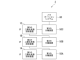
- FIG. 12 is a block diagram showing a carbon dioxide recovery system 3 according to the seventh embodiment.
- the carbon dioxide recovery system 3 according to the present embodiment includes a first carbon dioxide recovery device 1A, a second carbon dioxide recovery device 1B, and a third carbon dioxide recovery device 1C. , a first separation device 50A, a second separation device 50B, a third separation device 50C, and a methanation system 60.
- the carbon dioxide recovery devices 1A, 1B, and 1C and the separation devices 50A, 50B, and 50C are installed in a common building.
- the first carbon dioxide recovery device 1A and the first separation device 50A are installed on the first floor
- the second carbon dioxide recovery device 1B and the second separation device 50B are installed on the second floor
- the second carbon dioxide recovery device 1B and the second separation device 50B are installed on the second floor.
- the carbon dioxide recovery device 1C and the third separation device 50C are installed on the third floor. Note that even if the third carbon dioxide recovery device 1C and the third separation device 50C are installed on the first floor, and the first carbon dioxide recovery device 1A and the first separation device 50A are installed on the third floor, good.
- the configurations of the carbon dioxide recovery devices 1A, 1B, and 1C are similar to the carbon dioxide recovery device 1 according to the first embodiment. That is, the carbon dioxide recovery devices 1A, 1B, and 1C each have an adsorbent, a total heat exchanger 10, a first inflow duct 21, a first outflow duct 22, a second inflow duct 23, and a second outflow duct. 24.
- the second inflow duct 23 is provided with an adsorption area A1 in which carbon dioxide contained in the air is adsorbed by an adsorbent. Note that the suction area A1 may be provided in the first inflow duct 21.
- the separation devices 50A, 50B, and 50C have a function of separating carbon dioxide from the adsorbent.
- the separation devices 50A, 50B, and 50C may include a heater and heat the adsorbent to separate carbon dioxide.
- the separation devices 50A, 50B, and 50C may be equipped with a vacuum pump and may separate carbon dioxide by placing the adsorbent under reduced pressure conditions.
- the adsorbent adsorbing carbon dioxide is conveyed to the first separation device 50A from the first carbon dioxide recovery device 1A. Carbon dioxide separated from the adsorbent in the first separation device 50A is transported to the second carbon dioxide recovery device 1B. The adsorbent adsorbing carbon dioxide is conveyed to the second separation device 50B from the second carbon dioxide recovery device 1B. Carbon dioxide separated from the adsorbent in the second separation device 50B is transported to the third carbon dioxide recovery device 1C. The adsorbent adsorbing carbon dioxide is transported from the third carbon dioxide recovery device 1C to the third separation device 50C. Carbon dioxide separated from the adsorbent in the third separation device 50C is conveyed to the methanation system 60.
- the methanation system 60 has a function of generating methane using carbon dioxide, hydrogen, water, electricity, and the like.
- the methanation system 60 is installed on the roof of a building.
- the carbon dioxide recovery method includes an adsorption step, an adsorbent transport step, a separation step, and a carbon dioxide transport step.
- the adsorbent In the adsorption step, the adsorbent is brought into contact with air in the adsorption area A1 of the first carbon dioxide recovery device 1A, and carbon dioxide is adsorbed by the adsorbent.
- the adsorbent transport step the adsorbent that has adsorbed carbon dioxide is transported from the adsorption area A1 of the first carbon dioxide recovery device 1A to the first separation device 50A.
- the first separation device 50A separates carbon dioxide from the adsorbent that has adsorbed carbon dioxide.
- the separated carbon dioxide is transported to the second carbon dioxide recovery device 1B.
- an adsorption step, an adsorbent conveyance step, a separation step, and a carbon dioxide conveyance step are similarly performed. That is, in the second adsorption step, the adsorbent is brought into contact with air in the adsorption area A1 of the second carbon dioxide recovery device 1B, and carbon dioxide is adsorbed by the adsorbent. At this time, since the air flowing through the second carbon dioxide recovery device 1B is mixed with the carbon dioxide conveyed from the first separation device 50A, the air flowing through the first carbon dioxide recovery device 1A and In comparison, carbon dioxide concentration has increased.
- the adsorbent that has adsorbed carbon dioxide is transported from the adsorption area A1 of the second carbon dioxide recovery device 1B to the second separation device 50B.
- the second separation device 50B separates carbon dioxide from the adsorbent that has adsorbed carbon dioxide.
- the separated carbon dioxide is transported to the third carbon dioxide recovery device 1C.
- an adsorption process, an adsorbent conveyance process, a separation process, and a carbon dioxide conveyance process are similarly performed. That is, in the third adsorption step, the adsorbent is brought into contact with air in the adsorption area A1 of the third carbon dioxide recovery device 1C, and carbon dioxide is adsorbed by the adsorbent. At this time, the carbon dioxide concentration is further increased because the air flowing through the third carbon dioxide recovery device 1C is mixed with the carbon dioxide conveyed from the second separation device 50B.
- the adsorbent that has adsorbed carbon dioxide is transported from the adsorption area A1 of the third carbon dioxide recovery device 1C to the third separation device 50C.
- the third separation device 50C separates carbon dioxide from the adsorbent that has adsorbed carbon dioxide.
- the separated carbon dioxide is transported to the methanation system 60. In methanation system 60, carbon dioxide is recovered.
- the carbon dioxide concentration of the air to be adsorbed can be increased, thereby improving the carbon dioxide recovery efficiency. Further, the step of concentrating carbon dioxide becomes unnecessary. Furthermore, the recovered carbon dioxide can be easily transported to the methanation system 60.
- the carbon dioxide recovery method includes a separation step in which carbon dioxide is separated from the adsorbent that has adsorbed carbon dioxide in the adsorption step, and a second separation step in which the carbon dioxide separated in the separation step is A carbon dioxide transport step in which carbon dioxide is transported to the carbon dioxide recovery device 1B, and a second adsorption step in which air is brought into contact with an adsorbent that adsorbs carbon dioxide to adsorb carbon dioxide to the adsorbent in the second carbon dioxide recovery device 1B.
- the method further includes a step.
- the carbon dioxide separated in the separation step is mixed and the carbon dioxide contained in the air with increased carbon dioxide concentration is adsorbed onto the adsorbent, thereby further improving the carbon dioxide recovery efficiency. I can do it.
- FIG. 13 is a perspective view showing a carbon dioxide recovery system 4 according to the eighth embodiment.
- the carbon dioxide recovery system 4 according to the present embodiment includes a first carbon dioxide recovery device 1A, a second carbon dioxide recovery device 1B, and a transport duct 70.
- the second carbon dioxide recovery device 1B is arranged below the first carbon dioxide recovery device 1A.
- the basic configuration of the carbon dioxide recovery devices 1A and 1B is the same as the carbon dioxide recovery device 1 according to the first embodiment. That is, the carbon dioxide recovery devices 1A and 1B each include a total heat exchanger 10, a first inflow duct 21, a first outflow duct 22, a second inflow duct 23, and a second outflow duct 24. In this embodiment, a common adsorbent is used in carbon dioxide recovery apparatuses 1A and 1B.
- the second inflow duct 23 of the first carbon dioxide recovery device 1A is provided with an adsorption area A1 in which carbon dioxide contained in the air is adsorbed by an adsorbent.
- the adsorbent that has adsorbed carbon dioxide in the adsorption area A1 of the first carbon dioxide recovery device 1A is conveyed to the second outflow duct 24 of the second carbon dioxide recovery device 1B.
- the second outflow duct 24 of the second carbon dioxide recovery device 1B is provided with a separation area A2 that separates carbon dioxide from the adsorbent that has adsorbed carbon dioxide.
- the transport duct 70 connects the second inflow duct 23 of the first carbon dioxide recovery device 1A and the second outflow duct 24 of the second carbon dioxide recovery device 1B.
- the transport duct 70 is provided to intersect with the second inflow duct 23 of the first carbon dioxide recovery device 1A and the second outflow duct 24 of the second carbon dioxide recovery device 1B.
- the adsorbent is flowed into the transport duct 70. Further, the adsorbent that has adsorbed carbon dioxide in the second inflow duct 23 of the first carbon dioxide recovery device 1A is conveyed to the second outflow duct 24 of the second carbon dioxide recovery device 1B using the conveyance duct 70. Ru.
- the carbon dioxide recovery method includes an adsorption step, an adsorbent conveyance step, and a separation step.
- the adsorbent is flowed into the transport duct 70, and the adsorbent is brought into contact with air in the adsorption area A1 provided in the second inflow duct 23 of the first carbon dioxide recovery device 1A, so that carbon dioxide is transferred to the adsorbent. Let it be adsorbed to.
- the adsorbent conveyance process the adsorbent that has adsorbed carbon dioxide in the adsorption process is transferred from the second inflow duct 23 of the first carbon dioxide recovery apparatus 1A to the second outflow of the second carbon dioxide recovery apparatus 1B by the conveyance duct 70. It is conveyed to the duct 24.
- carbon dioxide is separated from the adsorbent that has adsorbed carbon dioxide in the separation area A2 provided in the second outflow duct 24 of the second carbon dioxide recovery device 1B.
- the adsorbent that has adsorbed carbon dioxide in the adsorption step is transferred to the second carbon dioxide recovery device disposed below the first carbon dioxide recovery device 1A.
- the method further includes a step of transporting the adsorbent to the recovery device 1B, and a separation step of separating carbon dioxide from the adsorbent that has adsorbed carbon dioxide in the second carbon dioxide recovery device 1B.
- the adsorbent is transported upward by a conveyor, blower, etc. Compared to conventional systems, it is possible to save energy and improve the carbon dioxide recovery efficiency of the entire system.
- the suction area A1 may be provided in both the first inflow duct 21 and the second inflow duct 23.
- the separation area A2 may be provided in the second inflow duct 23.
- a cylinder capable of storing carbon dioxide may be provided.
- carbon dioxide separated from the adsorbent by the separators 50A, 50B, and 50C can be stored in the cylinder.
- the cylinder storing carbon dioxide may be transported to another location (for example, a factory, etc.) and the carbon dioxide may be used.
- the carbon dioxide recovery apparatus 2 according to the fifth or sixth embodiment may be used as the carbon dioxide recovery apparatuses 1A, 1B, and 1C.
Landscapes
- Chemical & Material Sciences (AREA)
- Engineering & Computer Science (AREA)
- Analytical Chemistry (AREA)
- General Chemical & Material Sciences (AREA)
- Oil, Petroleum & Natural Gas (AREA)
- Chemical Kinetics & Catalysis (AREA)
- Combustion & Propulsion (AREA)
- Mechanical Engineering (AREA)
- General Engineering & Computer Science (AREA)
- Separation Of Gases By Adsorption (AREA)
- Treating Waste Gases (AREA)
Priority Applications (3)
| Application Number | Priority Date | Filing Date | Title |
|---|---|---|---|
| EP22944792.5A EP4534175A4 (en) | 2022-05-31 | 2022-05-31 | CARBON DIOXIDE RECOVERY DEVICE AND CARBON DIOXIDE RECOVERY PROCESS |
| JP2023523000A JP7433524B1 (ja) | 2022-05-31 | 2022-05-31 | 二酸化炭素回収装置、および二酸化炭素回収方法 |
| PCT/JP2022/022048 WO2023233503A1 (ja) | 2022-05-31 | 2022-05-31 | 二酸化炭素回収装置、および二酸化炭素回収方法 |
Applications Claiming Priority (1)
| Application Number | Priority Date | Filing Date | Title |
|---|---|---|---|
| PCT/JP2022/022048 WO2023233503A1 (ja) | 2022-05-31 | 2022-05-31 | 二酸化炭素回収装置、および二酸化炭素回収方法 |
Publications (1)
| Publication Number | Publication Date |
|---|---|
| WO2023233503A1 true WO2023233503A1 (ja) | 2023-12-07 |
Family
ID=89025928
Family Applications (1)
| Application Number | Title | Priority Date | Filing Date |
|---|---|---|---|
| PCT/JP2022/022048 Ceased WO2023233503A1 (ja) | 2022-05-31 | 2022-05-31 | 二酸化炭素回収装置、および二酸化炭素回収方法 |
Country Status (3)
| Country | Link |
|---|---|
| EP (1) | EP4534175A4 (https=) |
| JP (1) | JP7433524B1 (https=) |
| WO (1) | WO2023233503A1 (https=) |
Citations (6)
| Publication number | Priority date | Publication date | Assignee | Title |
|---|---|---|---|---|
| JP2013145065A (ja) * | 2012-01-13 | 2013-07-25 | Mitsubishi Electric Corp | 空気調和装置 |
| JP2016042009A (ja) * | 2014-08-19 | 2016-03-31 | 三菱重工業株式会社 | 換気システム |
| JP2020051658A (ja) * | 2018-09-26 | 2020-04-02 | パナソニックIpマネジメント株式会社 | 熱交換型換気装置 |
| JP2020089891A (ja) * | 2020-03-11 | 2020-06-11 | 株式会社西部技研 | 吸収式除去・濃縮装置 |
| JP2020199434A (ja) * | 2019-06-06 | 2020-12-17 | 昭和電工マテリアルズ株式会社 | 空調装置 |
| WO2022013972A1 (ja) * | 2020-07-15 | 2022-01-20 | 三菱電機株式会社 | 熱交換器および熱交換型換気装置 |
Family Cites Families (10)
| Publication number | Priority date | Publication date | Assignee | Title |
|---|---|---|---|---|
| JP2000161711A (ja) * | 1998-11-26 | 2000-06-16 | Noritz Corp | 換気空調装置 |
| US6575228B1 (en) * | 2000-03-06 | 2003-06-10 | Mississippi State Research And Technology Corporation | Ventilating dehumidifying system |
| JP5627870B2 (ja) * | 2009-10-27 | 2014-11-19 | 株式会社西部技研 | 空気調和装置 |
| CN205048633U (zh) * | 2015-08-25 | 2016-02-24 | 安徽省元琛环保科技有限公司 | 一种高效除甲醛的静电除尘型全热交换器 |
| US10962254B2 (en) * | 2015-08-31 | 2021-03-30 | Mitsubishi Electric Corporation | Ventilation device |
| JP6834255B2 (ja) * | 2016-08-30 | 2021-02-24 | 三菱電機株式会社 | 空気清浄システム |
| JP6383467B1 (ja) * | 2017-07-19 | 2018-08-29 | 株式会社西部技研 | 除湿空調装置 |
| JP6636217B2 (ja) * | 2017-11-16 | 2020-01-29 | 三菱電機株式会社 | 全熱交換素子および全熱交換器 |
| CN110871014A (zh) * | 2018-08-30 | 2020-03-10 | 开利公司 | 具有移动床结构的co2洗涤器 |
| KR102171376B1 (ko) * | 2019-04-19 | 2020-10-29 | (주)디지털 | 열교환 환기시스템 및 그 제어방법 |
-
2022
- 2022-05-31 JP JP2023523000A patent/JP7433524B1/ja active Active
- 2022-05-31 WO PCT/JP2022/022048 patent/WO2023233503A1/ja not_active Ceased
- 2022-05-31 EP EP22944792.5A patent/EP4534175A4/en active Pending
Patent Citations (6)
| Publication number | Priority date | Publication date | Assignee | Title |
|---|---|---|---|---|
| JP2013145065A (ja) * | 2012-01-13 | 2013-07-25 | Mitsubishi Electric Corp | 空気調和装置 |
| JP2016042009A (ja) * | 2014-08-19 | 2016-03-31 | 三菱重工業株式会社 | 換気システム |
| JP2020051658A (ja) * | 2018-09-26 | 2020-04-02 | パナソニックIpマネジメント株式会社 | 熱交換型換気装置 |
| JP2020199434A (ja) * | 2019-06-06 | 2020-12-17 | 昭和電工マテリアルズ株式会社 | 空調装置 |
| JP2020089891A (ja) * | 2020-03-11 | 2020-06-11 | 株式会社西部技研 | 吸収式除去・濃縮装置 |
| WO2022013972A1 (ja) * | 2020-07-15 | 2022-01-20 | 三菱電機株式会社 | 熱交換器および熱交換型換気装置 |
Non-Patent Citations (1)
| Title |
|---|
| See also references of EP4534175A4 * |
Also Published As
| Publication number | Publication date |
|---|---|
| JPWO2023233503A1 (https=) | 2023-12-07 |
| JP7433524B1 (ja) | 2024-02-19 |
| EP4534175A4 (en) | 2025-11-12 |
| EP4534175A1 (en) | 2025-04-09 |
Similar Documents
| Publication | Publication Date | Title |
|---|---|---|
| KR102546428B1 (ko) | 환기 공조 장치 | |
| JP6605548B2 (ja) | 換気空調装置 | |
| EP2351970B1 (en) | Desiccant air conditioning device | |
| JP7455566B2 (ja) | ガス除去濃縮装置 | |
| JP2011089665A (ja) | 調湿装置 | |
| JP2011033302A (ja) | 調湿換気装置 | |
| JP2002320817A (ja) | 除湿装置及び除湿方法 | |
| JP7262698B1 (ja) | 二酸化炭素回収装置、および二酸化炭素回収方法 | |
| KR102597628B1 (ko) | 재생배기 없는 하이브리드 데시칸트 제습기 및 제습방법 | |
| JP7433524B1 (ja) | 二酸化炭素回収装置、および二酸化炭素回収方法 | |
| JP2000205598A (ja) | 除湿空調方法およびその装置並びにその装置の使用方法 | |
| JP3861579B2 (ja) | 除湿機および局所空間用除湿機 | |
| JP7333882B1 (ja) | 二酸化炭素回収システム | |
| JP2002166124A (ja) | 吸着式除湿装置 | |
| JPH07275642A (ja) | 除湿装置 | |
| JP2006308247A (ja) | 調湿装置 | |
| JP4393478B2 (ja) | デシカント換気システム | |
| JP2005030754A (ja) | 流動層型デシカント空調システム | |
| JP2006239564A (ja) | Voc除去システム | |
| JP2006125693A (ja) | 浴室暖房換気除湿乾燥装置 | |
| JP2005337559A (ja) | 小型デシカント空調装置 | |
| JP2006239566A (ja) | 空気浄化システム | |
| JP4981502B2 (ja) | デシカント空調システム | |
| WO2026062923A1 (ja) | ガス回収装置 | |
| JP3770470B2 (ja) | 冷凍システム、及び冷凍方法 |
Legal Events
| Date | Code | Title | Description |
|---|---|---|---|
| ENP | Entry into the national phase |
Ref document number: 2023523000 Country of ref document: JP Kind code of ref document: A |
|
| 121 | Ep: the epo has been informed by wipo that ep was designated in this application |
Ref document number: 22944792 Country of ref document: EP Kind code of ref document: A1 |
|
| NENP | Non-entry into the national phase |
Ref country code: DE |
|
| WWE | Wipo information: entry into national phase |
Ref document number: 2022944792 Country of ref document: EP |
|
| ENP | Entry into the national phase |
Ref document number: 2022944792 Country of ref document: EP Effective date: 20250102 |
|
| WWP | Wipo information: published in national office |
Ref document number: 2022944792 Country of ref document: EP |