WO2023233495A1 - 二酸化炭素回収装置、空調換気システム及び二酸化炭素回収方法 - Google Patents
二酸化炭素回収装置、空調換気システム及び二酸化炭素回収方法 Download PDFInfo
- Publication number
- WO2023233495A1 WO2023233495A1 PCT/JP2022/022029 JP2022022029W WO2023233495A1 WO 2023233495 A1 WO2023233495 A1 WO 2023233495A1 JP 2022022029 W JP2022022029 W JP 2022022029W WO 2023233495 A1 WO2023233495 A1 WO 2023233495A1
- Authority
- WO
- WIPO (PCT)
- Prior art keywords
- carbon dioxide
- adsorbent
- adsorption
- space
- recovery device
- Prior art date
- Legal status (The legal status is an assumption and is not a legal conclusion. Google has not performed a legal analysis and makes no representation as to the accuracy of the status listed.)
- Ceased
Links
Images
Classifications
-
- B—PERFORMING OPERATIONS; TRANSPORTING
- B01—PHYSICAL OR CHEMICAL PROCESSES OR APPARATUS IN GENERAL
- B01D—SEPARATION
- B01D53/00—Separation of gases or vapours; Recovering vapours of volatile solvents from gases; Chemical or biological purification of waste gases, e.g. engine exhaust gases, smoke, fumes, flue gases, aerosols
- B01D53/02—Separation of gases or vapours; Recovering vapours of volatile solvents from gases; Chemical or biological purification of waste gases, e.g. engine exhaust gases, smoke, fumes, flue gases, aerosols by adsorption, e.g. preparative gas chromatography
- B01D53/06—Separation of gases or vapours; Recovering vapours of volatile solvents from gases; Chemical or biological purification of waste gases, e.g. engine exhaust gases, smoke, fumes, flue gases, aerosols by adsorption, e.g. preparative gas chromatography with moving adsorbents, e.g. rotating beds
- B01D53/08—Separation of gases or vapours; Recovering vapours of volatile solvents from gases; Chemical or biological purification of waste gases, e.g. engine exhaust gases, smoke, fumes, flue gases, aerosols by adsorption, e.g. preparative gas chromatography with moving adsorbents, e.g. rotating beds according to the "moving bed" method
-
- F—MECHANICAL ENGINEERING; LIGHTING; HEATING; WEAPONS; BLASTING
- F24—HEATING; RANGES; VENTILATING
- F24F—AIR-CONDITIONING; AIR-HUMIDIFICATION; VENTILATION; USE OF AIR CURRENTS FOR SCREENING
- F24F8/00—Treatment, e.g. purification, of air supplied to human living or working spaces otherwise than by heating, cooling, humidifying or drying
- F24F8/10—Treatment, e.g. purification, of air supplied to human living or working spaces otherwise than by heating, cooling, humidifying or drying by separation, e.g. by filtering
- F24F8/108—Treatment, e.g. purification, of air supplied to human living or working spaces otherwise than by heating, cooling, humidifying or drying by separation, e.g. by filtering using dry filter elements
-
- B—PERFORMING OPERATIONS; TRANSPORTING
- B01—PHYSICAL OR CHEMICAL PROCESSES OR APPARATUS IN GENERAL
- B01D—SEPARATION
- B01D2253/00—Adsorbents used in seperation treatment of gases and vapours
- B01D2253/10—Inorganic adsorbents
- B01D2253/102—Carbon
-
- B—PERFORMING OPERATIONS; TRANSPORTING
- B01—PHYSICAL OR CHEMICAL PROCESSES OR APPARATUS IN GENERAL
- B01D—SEPARATION
- B01D2253/00—Adsorbents used in seperation treatment of gases and vapours
- B01D2253/10—Inorganic adsorbents
- B01D2253/104—Alumina
-
- B—PERFORMING OPERATIONS; TRANSPORTING
- B01—PHYSICAL OR CHEMICAL PROCESSES OR APPARATUS IN GENERAL
- B01D—SEPARATION
- B01D2253/00—Adsorbents used in seperation treatment of gases and vapours
- B01D2253/10—Inorganic adsorbents
- B01D2253/106—Silica or silicates
-
- B—PERFORMING OPERATIONS; TRANSPORTING
- B01—PHYSICAL OR CHEMICAL PROCESSES OR APPARATUS IN GENERAL
- B01D—SEPARATION
- B01D2253/00—Adsorbents used in seperation treatment of gases and vapours
- B01D2253/10—Inorganic adsorbents
- B01D2253/106—Silica or silicates
- B01D2253/108—Zeolites
-
- B—PERFORMING OPERATIONS; TRANSPORTING
- B01—PHYSICAL OR CHEMICAL PROCESSES OR APPARATUS IN GENERAL
- B01D—SEPARATION
- B01D2253/00—Adsorbents used in seperation treatment of gases and vapours
- B01D2253/25—Coated, impregnated or composite adsorbents
-
- B—PERFORMING OPERATIONS; TRANSPORTING
- B01—PHYSICAL OR CHEMICAL PROCESSES OR APPARATUS IN GENERAL
- B01D—SEPARATION
- B01D2257/00—Components to be removed
- B01D2257/50—Carbon oxides
- B01D2257/504—Carbon dioxide
-
- B—PERFORMING OPERATIONS; TRANSPORTING
- B01—PHYSICAL OR CHEMICAL PROCESSES OR APPARATUS IN GENERAL
- B01D—SEPARATION
- B01D2258/00—Sources of waste gases
- B01D2258/06—Polluted air
-
- B—PERFORMING OPERATIONS; TRANSPORTING
- B01—PHYSICAL OR CHEMICAL PROCESSES OR APPARATUS IN GENERAL
- B01D—SEPARATION
- B01D2259/00—Type of treatment
- B01D2259/40—Further details for adsorption processes and devices
- B01D2259/40083—Regeneration of adsorbents in processes other than pressure or temperature swing adsorption
- B01D2259/40088—Regeneration of adsorbents in processes other than pressure or temperature swing adsorption by heating
- B01D2259/4009—Regeneration of adsorbents in processes other than pressure or temperature swing adsorption by heating using hot gas
-
- B—PERFORMING OPERATIONS; TRANSPORTING
- B01—PHYSICAL OR CHEMICAL PROCESSES OR APPARATUS IN GENERAL
- B01D—SEPARATION
- B01D2259/00—Type of treatment
- B01D2259/45—Gas separation or purification devices adapted for specific applications
- B01D2259/4508—Gas separation or purification devices adapted for specific applications for cleaning air in buildings
-
- Y—GENERAL TAGGING OF NEW TECHNOLOGICAL DEVELOPMENTS; GENERAL TAGGING OF CROSS-SECTIONAL TECHNOLOGIES SPANNING OVER SEVERAL SECTIONS OF THE IPC; TECHNICAL SUBJECTS COVERED BY FORMER USPC CROSS-REFERENCE ART COLLECTIONS [XRACs] AND DIGESTS
- Y02—TECHNOLOGIES OR APPLICATIONS FOR MITIGATION OR ADAPTATION AGAINST CLIMATE CHANGE
- Y02C—CAPTURE, STORAGE, SEQUESTRATION OR DISPOSAL OF GREENHOUSE GASES [GHG]
- Y02C20/00—Capture or disposal of greenhouse gases
- Y02C20/40—Capture or disposal of greenhouse gases of CO2
Definitions
- the present disclosure relates to a carbon dioxide recovery device, an air conditioning ventilation system, and a carbon dioxide recovery method.
- Patent Document 1 JP-A No. 2014-516785 discloses a reactor that removes carbon dioxide contained in gas. Specifically, carbon dioxide contained in the gas is adsorbed onto microbeads, thereby removing carbon dioxide from the gas.
- the gas flow direction is exactly opposite to the falling direction of the microbeads. Therefore, the flow resistance that the gas receives from the microbeads is large.
- the reactor of Patent Document 1 is applicable only to gas having high pressure such as steam discharged from a power plant or the like.
- a large area of land is required to install the reactor of Patent Document 1.
- the present disclosure has been made in view of the above-mentioned problems, and the purpose of the first aspect of the present disclosure is to provide carbon dioxide recovery that can be applied to gases having lower pressure and that can be made more compact. Its purpose is to provide equipment and air conditioning ventilation systems.
- the purpose of the second aspect of the present disclosure is to provide a carbon dioxide recovery method that is applicable to gases having lower pressures and can downsize a carbon dioxide recovery device.
- the carbon dioxide recovery device of the present disclosure includes a storage section that accommodates an adsorbent, a recovery section that recovers the adsorbent, and an adsorption section.
- a suction space is formed inside the suction section.
- the adsorption section is provided with an inlet through which gas containing carbon dioxide flows into the adsorption space.
- the adsorption section is arranged between the storage section and the recovery section.
- the adsorbent falls through the adsorption space from the storage section toward the collection section under its own weight. Gas is introduced into the adsorption space through the inlet in a direction transverse to the falling direction of the adsorbent.
- the adsorbent adsorbs carbon dioxide contained in the gas in the adsorption space.
- the air conditioning ventilation system of the present disclosure includes the carbon dioxide recovery device of the present disclosure.
- the adsorbent is dropped by its own weight in the adsorption space of the adsorption unit, and the adsorbent is brought into contact with the gas containing carbon dioxide, thereby removing the carbon dioxide contained in the gas into the adsorbent. It includes adsorption to. Gas is introduced into the adsorption space in a direction intersecting the direction in which the adsorbent falls.
- the carbon dioxide recovery method of the present disclosure further includes recovering the adsorbent on which carbon dioxide has been adsorbed.
- gas is introduced into the adsorption space in a direction that intersects with the direction in which the adsorbent falls. Therefore, the flow resistance experienced by the gas from the adsorbent is reduced.
- the carbon dioxide capture device and air conditioning ventilation system of the present disclosure is also applicable to gases with lower pressures and can be made more compact.
- gas is introduced into the adsorption space in a direction intersecting the falling direction of the adsorbent. Therefore, the flow resistance experienced by the gas from the adsorbent is reduced.
- the carbon dioxide recovery method of the present disclosure is also applicable to gases with lower pressures. According to the carbon dioxide recovery method of the present disclosure, the carbon dioxide recovery device can be further downsized.
- FIG. 1 is a schematic diagram of a carbon dioxide recovery device according to Embodiment 1.
- FIG. FIG. 2 is a schematic cross-sectional view taken along the cross-sectional line II-II shown in FIG. 1 of the carbon dioxide recovery device of the first embodiment.
- 1 is a schematic diagram of a carbon dioxide recovery device according to Embodiment 1.
- FIG. 4 is a schematic cross-sectional view taken along the cross-sectional line IV-IV shown in FIG. 3 of the carbon dioxide recovery device of Embodiment 1.
- FIG. 1 is a schematic diagram of a carbon dioxide recovery device according to Embodiment 1.
- FIG. 6 is a schematic cross-sectional view taken along the cross-sectional line VI-VI shown in FIG. 5 of the carbon dioxide recovery device of Embodiment 1.
- FIG. 2 is a schematic cross-sectional view of a carbon dioxide recovery device according to a first modification of the first embodiment.
- FIG. 3 is a schematic cross-sectional view of a carbon dioxide recovery device according to a second modification of the first embodiment.
- FIG. 3 is a schematic cross-sectional view of a carbon dioxide recovery device according to a third modification of the first embodiment. It is a schematic sectional view of the carbon dioxide recovery device of the fourth modification of Embodiment 1. It is a schematic sectional view of the carbon dioxide recovery device of the fifth modification of Embodiment 1.
- FIG. 2 is a schematic diagram showing a first installation example of the carbon dioxide recovery device according to the first embodiment.
- FIG. 2 is a schematic diagram showing a second installation example of the carbon dioxide recovery device according to the first embodiment.
- FIG. 3 is a schematic diagram showing a third installation example of the carbon dioxide recovery device according to the first embodiment.
- FIG. 2 is a schematic diagram of a carbon dioxide recovery device according to a second embodiment.
- FIG. 2 is a schematic diagram of a carbon dioxide recovery device according to a second embodiment.
- FIG. 2 is a schematic diagram of a carbon dioxide recovery device according to a second embodiment.
- FIG. 3 is a schematic diagram of a carbon dioxide recovery device according to a third embodiment.
- FIG. 3 is a schematic diagram of a carbon dioxide recovery device according to a third embodiment.
- FIG. 7 is a schematic diagram of a transport container included in the carbon dioxide recovery device of Embodiment 3.
- 21 is a schematic cross-sectional view taken along the cross-sectional line XXI-XXI shown in FIG.
- FIG. 3 is a schematic diagram of a carbon dioxide recovery device according to a third embodiment.
- FIG. 7 is a schematic diagram of a transport container included in the carbon dioxide recovery device of Embodiment 3.
- 24 is a schematic cross-sectional view taken along the cross-sectional line XXIV-XXIV shown in FIG. 23 of a transportation container included in the carbon dioxide recovery device of Embodiment 3.
- FIG. 3 is a schematic diagram of a carbon dioxide recovery device according to a third embodiment.
- FIG. 3 is a schematic diagram of a carbon dioxide recovery device according to a fourth embodiment.
- FIG. 3 is a schematic diagram of a carbon dioxide recovery device according to a fourth embodiment.
- FIG. 3 is a schematic diagram of a carbon dioxide recovery device according to a fourth embodiment.
- FIG. 3 is a schematic diagram of a carbon dioxide recovery device according to a fourth embodiment.
- FIG. 3 is a schematic diagram of a carbon dioxide recovery device according to a fourth embodiment.
- FIG. 3 is a schematic diagram of a carbon dioxide recovery device according to a fourth embodiment.
- FIG. 3 is a schematic diagram of a carbon dioxide recovery device according to a fourth embodiment.
- FIG. 3 is a schematic diagram of a carbon dioxide recovery device according to a fourth embodiment.
- FIG. 3 is a schematic diagram of a carbon dioxide recovery device according to a fourth embodiment.
- FIG. 7 is a schematic diagram of a carbon dioxide recovery device according to a modification of Embodiment 4.
- FIG. 7 is a schematic diagram of a carbon dioxide recovery device according to a modification of Embodiment 4.
- FIG. 7 is a schematic diagram of a carbon dioxide recovery device according to a modification of Embodiment 4.
- FIG. 7 is a schematic diagram of a carbon dioxide recovery device according to a modification of Embodiment 4.
- FIG. 7 is a schematic diagram of a carbon dioxide recovery device according to a modification of Embodiment 4.
- FIG. 7 is a schematic diagram of a carbon dioxide recovery device according to a modification of Embodiment 4.
- FIG. 7 is a schematic diagram of a carbon dioxide recovery device according to a modification of Embodiment 4.
- FIG. 7 is a schematic diagram of a carbon dioxide recovery device according to a modification of Embodiment 4.
- FIG. 7 is a schematic cross-sectional view of a carbon dioxide recovery device according to a fifth embodiment.
- FIG. 7 is a schematic cross-sectional view of a carbon dioxide recovery device according to a fifth embodiment.
- FIG. 7 is a schematic cross-sectional view of a carbon dioxide recovery device according to a fifth embodiment.
- FIG. 7 is a schematic cross-sectional view of a carbon dioxide recovery device according to a fifth embodiment.
- FIG. 7 is a schematic cross-sectional view of a carbon dioxide recovery device according to a first modification of the fifth embodiment.
- FIG. 7 is a schematic cross-sectional view of a carbon dioxide recovery device according to a second modification of the fifth embodiment.
- FIG. 7 is a schematic cross-sectional view of a carbon dioxide recovery device according to a second modification of the fifth embodiment.
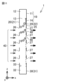
- Embodiment 1 A carbon dioxide recovery apparatus 1 according to a first embodiment will be described with reference to FIGS. 1 to 6.
- the carbon dioxide recovery device 1 includes a storage section 10, an adsorption section 20, and a recovery section 30.
- the storage section 10 accommodates the adsorbent 40.
- Adsorbent 40 can adsorb carbon dioxide.
- the adsorbent 40 is a solid absorbent that supports, for example, amine, zeolite, silica gel, diatomaceous earth, alumina, or activated carbon.
- the adsorbent 40 has, for example, a spherical shape or a cylindrical shape, although it is not particularly limited. In FIGS. 1 to 6 and the like, the more carbon dioxide is adsorbed on the adsorbent 40, the higher the black density of the adsorbent 40 becomes.
- the storage section 10 is arranged above the suction section 20.
- the storage section 10 includes a storage main body 11 and a valve 14.
- a storage space 12 in which the adsorbent 40 is stored is formed inside the storage body 11 .
- An opening 13 is provided in the storage body 11 (specifically, at the bottom of the storage body 11). The opening 13 communicates with the storage space 12 and the suction space of the suction section 20 .
- Valve 14 opens and closes opening 13. When the valve 14 closes the opening 13, the adsorbent 40 is stored in the reservoir 10. When the valve 14 opens the opening 13, the adsorbent 40 falls toward the adsorption space of the adsorption section 20 due to its own weight.
- the adsorption section 20 is arranged between the storage section 10 and the collection section 30. In the adsorption section 20 , the adsorbent 40 comes into contact with the gas 43 containing carbon dioxide and adsorbs the carbon dioxide contained in the gas 43 .
- the gas 43 is not particularly limited as long as it contains carbon dioxide, and is, for example, air.
- the suction section 20 includes a front wall 21 , a rear wall 22 on the opposite side to the front wall 21 , a side wall 23 , and a side wall 24 on the opposite side to the side wall 23 .
- Side walls 23 and 24 are connected to front wall 21 and rear wall 22, respectively.
- a suction space 25 is formed inside the suction section 20 .
- the front wall 21 , the rear wall 22 , and the side walls 23 and 24 define a suction space 25 .
- the front wall 21 has a wider width than each of the side walls 23 and 24.
- the rear wall 22 has a wider width than each of the side walls 23 and 24.
- the width of the front wall 21 is the length of the front wall 21 in the direction (y direction) perpendicular to the falling direction (-z direction) of the suction part 20.
- the width of the rear wall 22 is the length of the rear wall 22 in the direction (y direction) perpendicular to the falling direction (-z direction) of the suction section 20.
- the width of the side wall 23 is the length of the side wall 23 in the direction (x direction) perpendicular to the falling direction ( ⁇ z direction) of the suction part 20.
- the width of the side wall 24 is the length of the side wall 24 in the direction (x direction) perpendicular to the direction in which the suction section 20 falls ( ⁇ z direction).
- An opening 26 is provided in the suction portion 20 (specifically, the front wall 21). Gas 43 containing carbon dioxide flows into adsorption space 25 through opening 26 .
- opening 26 is an inlet for gas 43.
- the width of the opening 26 is, for example, 60% or more and 100% or less of the width of the front wall 21.
- the width of the opening 26 may be 80% or more and 95% or less of the width of the front wall 21.
- the width of the opening 26 is the length of the opening 26 in the direction (y direction) perpendicular to the falling direction (-z direction) of the suction section 20.
- a plurality of openings 26 are provided in the suction section 20, but it is sufficient that at least one opening 26 is provided in the suction section 20.
- An opening 27 is provided in the suction portion 20 (specifically, the rear wall 22). Gas 43 flows out of adsorption space 25 through opening 27 .
- opening 27 is an outlet for gas 43.
- the width of the opening 27 is, for example, 60% or more and 100% or less of the width of the rear wall 22. In this specification, the width of the opening 27 is the length of the opening 27 in the direction (y direction) perpendicular to the falling direction (-z direction) of the suction section 20.
- a plurality of openings 27 are provided in the suction section 20, but it is sufficient that at least one opening 27 is provided in the suction section 20.
- the opening 27 faces the opening 26, for example, in the direction (x direction) perpendicular to the falling direction ( ⁇ z direction) of the suction section 20.
- the adsorbent 40 falls through the adsorption space 25 from the storage section 10 toward the recovery section 30 due to its own weight.
- the falling direction (-z direction) of the adsorbent 40 is, for example, the direction of gravity.
- Gas 43 is introduced into adsorption space 25 through opening 26 in a direction (eg, +x direction) that intersects the falling direction of adsorbent 40 (eg, ⁇ z direction).
- the adsorbent 40 comes into contact with the gas 43 in the adsorption space 25 and adsorbs carbon dioxide contained in the gas 43. Gas 43 from which carbon dioxide has been removed by adsorbent 40 flows out of adsorption space 25 through opening 27 .
- the recovery unit 30 recovers the adsorbent 40 that has adsorbed carbon dioxide contained in the gas 43.
- the recovery section 30 is arranged below the adsorption section 20.
- the collection unit 30 includes a collection main body 31.
- a recovery space 32 is formed inside the recovery body 31 in which an adsorbent 40 adsorbing carbon dioxide is accommodated.
- An opening 33 is provided in the recovery body 31 (specifically, the top of the recovery body 31). The opening 33 communicates with the adsorption space 25 and the recovery space 32.
- the recovery unit 30 may be detachable from the adsorption unit 20.
- valve 14 closes the opening 13.
- the adsorbent 40 is stored in the storage section 10.
- the valve 14 opens the opening 13.
- the adsorbent 40 falls toward the adsorption space 25 of the adsorption section 20 due to its own weight.
- the adsorbent 40 falls through the adsorption space 25 from the storage section 10 toward the collection section 30 due to its own weight.
- Gas 43 is introduced into adsorption space 25 through opening 26 in a direction (eg, +x direction) that intersects the falling direction of adsorbent 40 (eg, -z direction).
- the adsorbent 40 comes into contact with the gas 43 in the adsorption space 25 and adsorbs carbon dioxide contained in the gas 43. Gas 43 from which carbon dioxide has been removed by adsorbent 40 flows out of adsorption space 25 through opening 27 .
- the adsorbent 40 that has adsorbed carbon dioxide contained in the gas 43 falls from the adsorption section 20 toward the recovery section 30 due to its own weight. As shown in FIGS. 5 and 6, the adsorbent 40 that has adsorbed carbon dioxide passes through the opening 33 and is accommodated in the recovery space 32 of the recovery unit 30. The adsorbent 40 that has adsorbed carbon dioxide is recovered by the recovery section 30.
- one opening 26 is provided in the adsorption section 20 (specifically, the front wall 21), and one opening 26 is provided in the adsorption section 20 (specifically, the front wall 21).
- Two openings 27 are provided in the suction portion 20 (specifically, the rear wall 22). The openings 27 are arranged offset from the corresponding openings 26 in the direction in which the adsorbent 40 falls (for example, in the -z direction).
- the opening 26 may function as an inlet for the gas 43, and the opening 27 may function as an outlet for the gas 43, or the opening 27 may function as an inlet for the gas 43. , and the opening 26 may function as an outlet for the gas 43.
- one opening 26 and one opening 27 are provided in the front wall 21 of the adsorption section 20.
- the openings 27 are arranged offset from the corresponding openings 26 in the direction in which the adsorbent 40 falls (for example, in the -z direction).
- the opening 26 may function as an inlet for the gas 43
- the opening 27 may function as an outlet for the gas 43
- the opening 27 may function as an inlet for the gas 43.
- the opening 26 may function as an outlet for the gas 43.
- the carbon dioxide recovery device 1 of the second modification of the present embodiment is suitable for installation on a wall (not shown).
- one opening 28 is provided in the front wall 21 of the adsorption section 20.
- Aperture 28 is larger than each of apertures 26 and 27.
- the opening 28 functions as an inlet and an outlet for the gas 43.
- the upper part of the opening 28 may function as an inlet for the gas 43 and the lower part of the opening 28 may function as an outlet for the gas 43;
- the upper part of the opening 28 may also function as an outlet for the gas 43.
- the carbon dioxide recovery device 1 of the third modification of the present embodiment is suitable for installation on a wall (not shown).
- the adsorption unit 20 includes an eave 29 provided above each of the openings 26 and 27.
- the eaves 29 prevent rain, snow, or sunlight from entering the suction space 25.
- the eaves 29 may be provided above either the opening 26 or the opening 27.
- the adsorption section 20 includes a net 46 that allows the gas 43 to pass through but does not allow the adsorbent 40 to pass therethrough.
- a mesh 46 covers the opening 27.
- the mesh 46 is made of metal such as stainless steel, but is not particularly limited. Screening 46 may further cover opening 26.
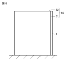
- the carbon dioxide recovery device 1 is installed in a building 50, for example.
- Building 50 includes a side wall 51 and a rooftop 52.
- the building 50 is, for example, a high-rise building or an apartment, although it is not particularly limited.
- the carbon dioxide recovery device 1 is installed on a side wall 51 of a building 50. As shown in FIG. 13, in the second installation example of this embodiment, the carbon dioxide recovery device 1 is installed on the rooftop 52 of a building 50. By installing the carbon dioxide recovery device 1 outdoors in this way, the gas 43 flows into the adsorption unit 20 due to the wind blowing outdoors, so the carbon dioxide recovery device 1 can recover the carbon dioxide contained in the gas 43. I can do it.
- the carbon dioxide recovery device 1 is installed in front of the air intake port 56 of the air conditioner outdoor unit 55.
- the carbon dioxide recovery device 1 may be supported by the air conditioner outdoor unit 55.
- the air conditioner outdoor unit 55 is installed outdoors, for example, on the rooftop 52 of the building 50, although it is not particularly limited.
- the air conditioning outdoor unit 55 is provided with an air intake port 56 and an air exhaust port 57.
- the carbon dioxide recovery device 1 and the air conditioning outdoor unit 55 are included in the air conditioning ventilation system 2 of this embodiment.
- the air conditioning ventilation system 2 means a system that performs air conditioning, ventilation, or both air conditioning and ventilation of the building 50.
- the carbon dioxide recovery device 1 of this embodiment includes a storage section 10 that accommodates the adsorbent 40, a recovery section 30 that collects the adsorbent 40, and an adsorption section 20.
- a suction space 25 is formed inside the suction section 20 .
- the adsorption unit 20 is provided with an inlet (for example, an opening 26 ) through which gas 43 containing carbon dioxide flows into the adsorption space 25 .
- the adsorption section 20 is arranged between the storage section 10 and the recovery section 30. The adsorbent 40 falls through the adsorption space 25 from the storage section 10 toward the collection section 30 due to its own weight.
- the gas 43 is introduced into the adsorption space 25 through the inlet in a direction intersecting the direction in which the adsorbent 40 falls.
- the adsorbent 40 adsorbs carbon dioxide contained in the gas 43 in the adsorption space 25 .
- the gas 43 is introduced into the adsorption space 25 in a direction intersecting the direction in which the adsorbent 40 falls. Therefore, the flow resistance that the gas 43 receives from the adsorbent 40 is reduced.
- the carbon dioxide recovery device 1 is also applicable to gas 43 having a lower pressure and can be made more compact. Further, the adsorbent 40 falls through the adsorption space 25 from the storage section 10 toward the recovery section 30 due to its own weight. Therefore, the power required to transport the adsorbent 40 from the storage section 10 to the recovery section 30 (for example, the power used for the pneumatic transport device for transporting the adsorbent 40) can be reduced.
- the storage section 10 is arranged above the adsorption section 20.
- the recovery section 30 is arranged below the adsorption section 20.
- the adsorbent 40 passes through the adsorption section 20 and falls from the storage section 10 to the collection section 30 due to its own weight.
- the power required to transport the adsorbent 40 from the storage section 10 to the recovery section 30 can be reduced.
- the eaves 29 prevent rain, snow, or sunlight from entering the suction space 25. Therefore, rain or snow is prevented from coming into contact with the adsorbent 40, or the adsorbent 40 is prevented from being irradiated by sunlight. A decrease in the adsorption capacity of the adsorbent 40 due to rain, snow, or sunlight can be prevented. Over a longer period of time, the carbon dioxide contained in gas 43 can be recovered more efficiently.
- the adsorption unit 20 includes a net 46 that allows the gas 43 to pass through but does not allow the adsorbent 40 to pass through.
- the adsorption section 20 is provided with an outlet (for example, an opening 27) through which the gas 43 flows out from the adsorption space 25.
- a screen 46 covers the outlet.
- the air conditioning ventilation system 2 includes the carbon dioxide recovery device 1, the air conditioning ventilation system 2 can also be applied to gas 43 having a lower pressure and can be made more compact. Further, by installing the carbon dioxide recovery device 1 in front of the air intake port 56 of the air conditioner outdoor unit 55, the gas 43 can be introduced into the adsorption space 25 using the flow of outside air generated by the air conditioner outdoor unit 55. Carbon dioxide contained in the gas 43 can be recovered more efficiently. Furthermore, even if the air conditioner outdoor unit 55 is stopped and there is no air flow generated by the air conditioner outdoor unit 55, the gas 43 flows into the adsorption unit 20 due to the wind blowing outdoors, so the carbon dioxide recovery device 1 can absorb the gas 43. The carbon dioxide contained can be recovered.
- the adsorbent 40 is dropped by its own weight in the adsorption space 25 of the adsorption unit 20, and the adsorbent 40 is brought into contact with the gas 43 containing carbon dioxide. 43 is adsorbed onto the adsorbent 40. Gas 43 is introduced into adsorption space 25 in a direction intersecting the direction in which adsorbent 40 falls.
- the carbon dioxide recovery method of this embodiment further includes recovering the adsorbent 40 on which carbon dioxide has been adsorbed.
- Embodiment 2 A carbon dioxide recovery device 1b according to the second embodiment will be described with reference to FIGS. 15 to 17.
- the carbon dioxide recovery device 1b of the present embodiment has the same configuration as the carbon dioxide recovery device 1 of the first embodiment, but differs from the carbon dioxide recovery device 1 of the first embodiment mainly in the following points. .
- the carbon dioxide recovery device 1b further includes a plurality of inclined plates 61 and 62.
- the carbon dioxide recovery device 1b only needs to include at least one inclined plate.
- the inclined plates 61 and 62 are arranged within the suction space 25.
- the inclined plates 61 and 62 are inclined with respect to the horizontal plane (xy plane).
- the adsorbent 40 rolls on the inclined plates 61 and 62 due to its own weight. Therefore, the adsorbent 40 can contact the gas 43 over a larger surface area. The time during which the adsorbent 40 is in contact with the gas 43 is extended. More carbon dioxide is adsorbed by the adsorbent 40.
- the adsorbent 40 only needs to have a shape that allows it to roll on the inclined plates 61 and 62, for example, a spherical shape or a cylindrical shape.
- the valve 14 closes the opening 13. Similar to the steps shown in FIGS. 1 and 2 of the first embodiment, the adsorbent 40 is stored in the storage section 10. The adsorbent 40 is on the inclined bottom plate 11b and the valve 14.
- the carbon dioxide recovery device 1b and the carbon dioxide recovery method of the present embodiment have the following effects.
- the carbon dioxide recovery device 1b of the present embodiment further includes at least one inclined plate (for example, inclined plates 61 and 62) that is disposed within the adsorption space 25 and is inclined with respect to a horizontal plane.
- the adsorbent 40 rolls on at least one inclined plate under its own weight.
- the adsorbent 40 rolls on at least one inclined plate (for example, inclined plates 61, 62), the surface area of the adsorbent 40 that comes into contact with the carbon dioxide-containing gas 43 increases. More carbon dioxide can be adsorbed onto the adsorbent 40 in a shorter time. Carbon dioxide can be recovered more efficiently.
- the carbon dioxide recovery device 1b can be downsized.
- At least one inclined plate (for example, the inclined plate 61) has a first end (for example, the end 61a) fixed to the adsorption section 20, and a first end that is fixed to the adsorption section 20. and a second end (for example, end 61b) on the opposite side.
- the first distance between the first end and the reservoir 10 is smaller than the second distance between the second end and the reservoir 10.
- the adsorbent 40 rolls on at least one inclined plate (for example, inclined plate 61).
- the surface area of the adsorbent 40 that comes into contact with the carbon dioxide-containing gas 43 increases. More carbon dioxide can be adsorbed onto the adsorbent 40 in a shorter time. Carbon dioxide can be recovered more efficiently.
- the carbon dioxide recovery device 1b can be downsized.
- At least one inclined plate is a plurality of inclined plates (for example, inclined plates 61 and 62).
- the surface area of the adsorbent 40 that comes into contact with the carbon dioxide-containing gas 43 further increases.
- the time during which the adsorbent 40 is in contact with the gas 43 is extended. More carbon dioxide can be adsorbed onto the adsorbent 40. Carbon dioxide can be recovered more efficiently.
- the adsorbent 40 rolls on at least one inclined plate (for example, inclined plates 61 and 62).
- the surface area of the adsorbent 40 that comes into contact with the carbon dioxide-containing gas 43 increases. More carbon dioxide can be adsorbed onto the adsorbent 40 in a shorter time. Carbon dioxide can be recovered more efficiently.
- dropping the adsorbent 40 by its own weight is performed using at least one inclined plate (for example, This involves rolling the adsorbent 40 onto the inclined plates 61, 62).
- the adsorbent 40 rolls on at least one inclined plate (for example, inclined plates 61, 62), the surface area of the adsorbent 40 that comes into contact with the carbon dioxide-containing gas 43 increases. More carbon dioxide can be adsorbed onto the adsorbent 40 in a shorter time. According to the carbon dioxide recovery method of this embodiment, carbon dioxide can be recovered more efficiently and the carbon dioxide recovery device 1b can be downsized.
- Embodiment 3 A carbon dioxide recovery apparatus 1c according to Embodiment 3 will be described with reference to FIGS. 18 to 25.
- the carbon dioxide recovery device 1c of this embodiment has the same configuration as the carbon dioxide recovery device 1b of the second embodiment, but differs from the carbon dioxide recovery device 1b of the second embodiment mainly in the following points. .
- the storage section 10 is provided with an opening 16.
- the opening 16 communicates with the storage space 12 and the passage 75 of the transport container 65 .
- the suction portion 20 is provided with an opening 63 that communicates with the suction space 25 and the passage 75 of the transport container 65 .
- the opening 63 faces the lower end of the inclined plate (for example, the end 62b of the inclined plate 62) closest to the collecting section 30 among the inclined plates 61 and 62.
- the suction unit 20 includes a valve 64.
- the valve 64 is provided at the lower end of the inclined plate (for example, the end 62b of the inclined plate 62) which is closest to the collecting section 30 among the inclined plates 61 and 62.
- Valve 64 is switchable between a first valve position (see FIGS. 18 and 19) and a second valve position (see FIGS. 22 and 25).
- first valve position see FIGS. 18 and 19
- second valve position see FIGS. 22 and 25
- valve 64 guides adsorbent 40 into opening 63 and transfer container 65.
- FIGS. As shown in FIGS. 22 and 25, when the valve 64 is in the second valve position, the valve 64 guides the adsorbent 40 to the opening 33 and the collection section 30.
- the carbon dioxide recovery device 1c further includes a transport container 65 and a drive device 77.
- the transport container 65 and the drive device 77 transport the adsorbent 40 on which carbon dioxide has been adsorbed from the adsorption unit 20 to the storage unit 10 .
- the transport container 65 includes a cage 66 and a shutter 70.
- the transport container 65 may further include a spring 73 and an operating rod 74.
- the cage 66 has a top surface 66t.
- a housing space 67 in which the adsorbent 40 is housed is provided inside the cage 66 .
- the cage 66 is provided with an opening 68 that communicates with the accommodation space 67.
- the cage 66 includes an inclined bottom surface 69 that defines the bottom surface of the storage space 67 .
- the inclined bottom surface 69 gradually descends toward the opening 68.
- the transport container 65 When the transport container 65 is in the first position as shown in FIGS. 18 and 19, the top surface 66t of the car 66 is separated from the ceiling 76 of the passage 75 of the transport container 65. As shown in FIGS. 18 to 21, the shutter 70 is urged upward by a spring 73. Therefore, the shutter 70 (specifically, the shutter body 71) partially closes the opening 68 of the car 66. The upper end 74b of the operating rod 74 protrudes from the top surface 66t of the car 66.
- valve 14 closes the opening 13. Similar to the process shown in FIG. 15 of the second embodiment, the adsorbent 40 is stored in the storage section 10.
- the adsorbent 40 is supplied from the transport container 65 to the storage section 10. Specifically, when the transport container 65 is in the second position, the transport container 65 faces the opening 16, and the top surface 66t of the cage 66 contacts the ceiling 76 of the passage 75 of the transport container 65. The upper end 74b of the operating rod 74 contacts the ceiling 76, and the operating rod 74 moves downward against the biasing force of the spring 73. The upper end 74b of the operating rod 74 is flush with the top surface 66t of the car 66. The shutter 70 connected to the operating rod 74 also moves downward. The shutter 70 (specifically, the shutter body 71) opens all the openings 68 of the car 66.
- the adsorbent 40 rolls again on the inclined plates 61 and 62 under its own weight. In the adsorption space 25, the adsorbent 40 comes into contact with the gas 43 again while rolling on the inclined plates 61 and 62, and adsorbs carbon dioxide contained in the gas 43. The steps shown in FIGS. 18, 19, and 22 are repeated until the adsorbent 40 sufficiently adsorbs carbon dioxide. Adsorbent 40 is reused to remove carbon dioxide contained in gas 43.
- the adsorbent 40 can be used repeatedly. Carbon dioxide can be recovered more efficiently. Furthermore, since the adsorbent 40 is reused, the size of the adsorption section 20 (particularly the size of the adsorption section 20 in the direction in which the adsorption agent 40 falls (-z direction)) can be reduced. The carbon dioxide recovery device 1c can be downsized.
- Embodiment 4 A carbon dioxide recovery device 1d according to the fourth embodiment will be described with reference to FIGS. 26 to 33.
- the carbon dioxide recovery device 1d of this embodiment has the same configuration as the carbon dioxide recovery device 1c of the third embodiment, but differs from the carbon dioxide recovery device 1c of the third embodiment mainly in the following points. .
- the recovery section 30 is further provided with openings 34, 35, and 36.
- the opening 34 communicates with the collection space 32 and the passage 75 of the transport container 65 .
- the openings 35 and 36 each communicate with the recovery space 32.
- the recovery unit 30 further includes valves 80, 81, 82, and 83.
- Valve 80 opens and closes opening 33.
- Valve 81 opens and closes opening 34 .
- Valve 82 opens and closes opening 35 .
- Valve 83 opens and closes opening 36 .
- the recovery section 30 includes an inclined bottom surface 31b. The inclined bottom surface 31b gradually descends toward the opening 34.
- the drive device 77 can also move the transport container 65 to a third position (see FIGS. 29 to 32).
- the drive device 77 moves the transport container 65 between a first position (see FIGS. 26 and 27), a second position (see FIGS. 28 and 33), and a third position (see FIGS. 29 to 32). move between.
- the transport container 65 faces the collection section 30 (specifically, the opening 34).
- the valve 81 opens the opening 34, the adsorbent 40 is supplied from the collection section 30 to the transport container 65.
- the heating device 84a heats the adsorbent 40 accommodated in the recovery space 32.
- the heating device 84a includes a pipe 85 and an air supply blower 86.
- the pipe 85 is connected to the recovery section 30 and communicates with the opening 35.
- the air supply blower 86 supplies hot air 90 from the pipe 85 to the recovery space 32 of the recovery unit 30 through the opening 35.
- the adsorbent 40 housed in the recovery space 32 and adsorbed with carbon dioxide is heated by the hot air 90 .
- the carbon dioxide adsorbed on the adsorbent 40 is separated from the adsorbent 40.
- the valve 14 opens the opening 13. Similar to the process shown in FIG. 19 of the third embodiment, the adsorbent 40 falls toward the adsorption space 25 of the adsorption section 20 due to its own weight. In the adsorption section 20 , the adsorbent 40 falls toward the collection section 30 while rolling on the inclined plates 61 and 62 under its own weight. The adsorbent 40 contacts the gas 43 while rolling on the inclined plates 61 and 62 in the adsorption space 25, and adsorbs carbon dioxide contained in the gas 43.
- the transport container 65 is in the first position and the valve 64 is in the first valve position.
- the transport container 65 is moved from the first position (see FIGS. 26 and 27) to the second position. (See Figure 28).
- the shutter 70 opens all of the openings 68 of the car 66.
- the adsorbent 40 moves along the inclined bottom surface 69.
- the adsorbent 40 moves from the storage space 67 of the cage 66 through the opening 16 to the storage space 12 of the storage section 10.
- the valve 14 opens the opening 13.
- the adsorbent 40 is supplied to the adsorption space 25 of the adsorption section 20 through the opening 13 .
- the adsorbent 40 rolls again on the inclined plates 61 and 62 under its own weight.
- the adsorbent 40 comes into contact with the gas 43 again while rolling on the inclined plates 61 and 62, and adsorbs carbon dioxide contained in the gas 43.
- the steps shown in FIGS. 26 to 28 are repeated until the adsorbent 40 sufficiently adsorbs carbon dioxide.
- Adsorbent 40 is reused to remove carbon dioxide contained in gas 43.
- the valve 64 closes to the first valve, similar to the steps shown in FIGS. 22 and 25 of the third embodiment. position (see FIGS. 26 and 27) to a second valve position (see FIGS. 28 and 29).
- FIGS. 28 and 29 when the valve 64 is in the second valve position, the valve 64 guides the adsorbent 40 to the opening 33 and the collection section 30.
- Valve 80 opens opening 33.
- the adsorbent 40 that has adsorbed carbon dioxide falls toward the recovery unit 30 from the inclined plate (inclined plate 62) closest to the recovery unit 30 among the inclined plates 61 and 62 due to its own weight.
- the adsorbent 40 that has adsorbed carbon dioxide passes through the opening 33 and is accommodated in the recovery space 32 of the recovery unit 30.
- the adsorbent 40 that has adsorbed carbon dioxide is recovered by the recovery section 30.
- the drive device 77 is used to move the transport container 65 from the second position (see FIGS. 27 and 28) to the third position (see FIGS. 29 to 32).
- the transport container 65 faces the collection section 30 (specifically, the opening 34).
- the transport container 65 may be moved from the second position to the third position before the valve 81 opens the opening 34.
- the shutter 70 partially closes the opening 68 of the car 66. Therefore, the adsorbent 40 accommodated in the accommodation space 67 of the cage 66 remains within the accommodation space 67 of the cage 66 .
- the transport container 65 is moved from the third position (see FIG. 32) to the second position (see FIG. 33) using the drive device 77. Specifically, the rope 79 is wound up using the hoisting machine 78. The transport container 65, which is connected to the rope 79, moves from the third position to the second position.
- the storage section 10 may include the valve 14 of the carbon dioxide recovery device 1 of the first embodiment.
- the operation of the carbon dioxide recovery device 1e and the carbon dioxide recovery method of a modification of the present embodiment will be described.
- the operation and carbon dioxide recovery method of the carbon dioxide recovery device 1e of the modified example of this embodiment are the same as the operation and carbon dioxide recovery method of the carbon dioxide recovery device 1d of this embodiment.
- valve 14 closes the opening 13. Similar to the steps shown in FIGS. 1 and 2 of the first embodiment, the adsorbent 40 is stored in the storage section 10.
- the adsorbent 40 that has adsorbed carbon dioxide contained in the gas 43 falls from the adsorption section 20 toward the recovery section 30 due to its own weight. As shown in FIG. 36, the adsorbent 40 that has adsorbed carbon dioxide passes through the opening 33 and is accommodated in the recovery space 32 of the recovery unit 30. The adsorbent 40 that has adsorbed carbon dioxide is recovered by the recovery section 30.
- Carbon dioxide is separated from the adsorbent 40 housed in the recovery space 32 using the carbon dioxide separation device 84.
- the carbon dioxide separation device 84 Similar to the process shown in FIG. 30 of this embodiment, by heating the adsorbent 40 on which carbon dioxide has been adsorbed, the adsorbent 40 on which carbon dioxide has been adsorbed is removed. Separate carbon dioxide.
- the carbon dioxide separated from the heated adsorbent 40 is exhausted from the recovery space 32 using the exhaust device 84b, similar to the process shown in FIG. 31 of this embodiment. Carbon dioxide separated from the adsorbent 40 is collected into a cylinder 89.
- valve 81 opens the opening 34 and the adsorbent 40 from which carbon dioxide has been separated is transferred to the recovery space of the recovery unit 30. 32 to the accommodation space 67 of the car 66.
- the adsorbent 40 from which carbon dioxide has been separated is accommodated in the accommodation space 67 of the cage 66 .
- the drive device 77 is used to move the transport container 65 from the third position (see FIG. 39) to the second position (see FIG. ).
- the shutter 70 opens all of the openings 68 of the car 66.
- the adsorbent 40 moves from the storage space 67 of the cage 66 through the opening 16 to the storage space 12 of the storage section 10.
- Valve 14 opens opening 13.
- the adsorbent 40 is supplied to the adsorption space 25 of the adsorption section 20 through the opening 13 .
- the adsorbent 40 falls through the adsorption space 25 from the storage section 10 toward the collection section 30 due to its own weight.
- the adsorbent 40 comes into contact with the gas 43 again in the adsorption space 25 and adsorbs carbon dioxide contained in the gas 43. In this way, the adsorbent 40 is reused to remove carbon dioxide contained in the gas 43.
- the remaining adsorbent 40 is brought into contact with the gas 43 in the adsorption section 20,
- the remaining adsorbent 40 may adsorb carbon dioxide contained in the gas 43. Since the carbon dioxide separation step and the carbon dioxide adsorption step are performed in parallel, carbon dioxide carbon can be recovered more efficiently.
- the carbon dioxide recovery devices 1d and 1e and the carbon dioxide recovery method of the present embodiment have the following effects.
- the carbon dioxide recovery devices 1d and 1e of this embodiment further include a carbon dioxide separation device 84, a transport container 65, and a drive device 77.
- the drive device 77 moves the transport container 65 from the third position facing the collection unit 30 to the second position facing the storage unit 10 .
- a recovery space 32 is formed inside the recovery unit 30 in which the adsorbent 40 that has fallen through the adsorption space 25 is accommodated.
- the carbon dioxide separator 84 separates carbon dioxide from the adsorbent 40 housed in the recovery space 32 .
- the transport container 65 is in the third position, the adsorbent 40 from which carbon dioxide has been separated is stored in the transport container 65 from the recovery unit 30 .
- the transport container 65 is in the second position, the adsorbent 40 is supplied from the transport container 65 to the reservoir 10 .
- the adsorbent 40 from which carbon dioxide has been separated can be reused to remove carbon dioxide contained in the gas 43. Carbon dioxide can be recovered more efficiently. Furthermore, since the adsorbent 40 is reused, the size of the adsorption section 20 (particularly the size of the adsorption section 20 in the direction in which the adsorption agent 40 falls (-z direction)) can be reduced. The carbon dioxide recovery devices 1d and 1e can be downsized.
- the carbon dioxide separation device 84 includes a heating device 84a that heats the adsorbent 40 housed in the recovery space 32, and a carbon dioxide separated from the heated adsorbent 40. and an exhaust device 84b that exhausts carbon from the recovery space 32.
- the recovery unit 30 is provided with a second opening (opening 34) that communicates with the recovery space 32.
- the transport container 65 faces the second opening.
- the recovery unit 30 includes a second valve (valve 81) that opens and closes the second opening.
- the adsorbent 40 from which carbon dioxide has been sufficiently separated can be supplied to the storage section 10 using the transport container 65. Carbon dioxide can be recovered more efficiently.
- the carbon dioxide recovery method of this embodiment involves separating carbon dioxide from the adsorbent 40 on which carbon dioxide has been adsorbed, and dropping the adsorbent 40 on which carbon dioxide has been adsorbed in the adsorption space 25 due to its own weight.
- the method further includes the step of causing the adsorbent 40 from which carbon dioxide has been separated to be brought into contact with the gas 43 again, thereby causing the carbon dioxide contained in the gas 43 to be adsorbed onto the adsorbent 40 from which carbon dioxide has been separated.
- carbon dioxide is separated from the adsorbent 40 on which carbon dioxide has been adsorbed by heating the adsorbent 40 on which carbon dioxide has been adsorbed.
- carbon dioxide can be efficiently separated from the adsorbent 40.
- the adsorbent 40 from which carbon dioxide has been separated can be reused. Carbon dioxide can be recovered more efficiently.
- the carbon dioxide recovery method of this embodiment further includes recovering carbon dioxide separated from the adsorbent 40. Therefore, carbon dioxide can be recovered more efficiently.
- Embodiment 5 A carbon dioxide recovery apparatus 1f according to the fifth embodiment will be described with reference to FIGS. 41 to 43.
- the carbon dioxide recovery device 1f of this embodiment has the same configuration as the carbon dioxide recovery device 1 of the first embodiment, but differs from the carbon dioxide recovery device 1 of the first embodiment mainly in the following points. .
- the carbon dioxide recovery device 1f is connected to a duct 93 installed within the building 50 (see FIGS. 12 to 14).
- the duct 93 is, for example, a ventilation duct or an air conditioning duct.
- the carbon dioxide recovery device 1f and the duct 93 are included in the air conditioning ventilation system 2f of this embodiment.
- the duct 93 includes an upstream duct portion 93a and a downstream duct portion 93b.
- Gas 43 containing carbon dioxide flows from the upstream duct portion 93a to the downstream duct portion 93b.
- the carbon dioxide recovery device 1f is arranged between the upstream duct portion 93a and the downstream duct portion 93b.
- the upstream duct portion 93a is arranged on the upstream side of the gas 43 with respect to the carbon dioxide recovery device 1f.
- the upstream duct portion 93a is connected to the carbon dioxide recovery device 1f and communicates with the opening 26.
- the downstream duct portion 93b is arranged downstream of the gas 43 with respect to the carbon dioxide recovery device 1f.
- the downstream duct portion 93b is connected to the carbon dioxide recovery device 1f and communicates with the opening 27.
- the operation of the carbon dioxide recovery device 1f and the carbon dioxide recovery method of this embodiment will be described with reference to FIGS. 41 to 43.
- the operation and carbon dioxide recovery method of the carbon dioxide recovery device 1f of this embodiment are the same as the operation and carbon dioxide recovery method of the carbon dioxide recovery device 1 of the first embodiment.
- valve 14 closes the opening 13. Similar to the steps shown in FIGS. 1 and 2 of the first embodiment, the adsorbent 40 is stored in the storage section 10.
- the valve 14 opens the opening 13. Similar to the steps shown in FIGS. 3 and 4 of the first embodiment, the adsorbent 40 falls toward the adsorption space 25 of the adsorption section 20 due to its own weight. In the adsorption section 20, the adsorbent 40 falls through the adsorption space 25 from the storage section 10 toward the collection section 30 due to its own weight. Gas 43 containing carbon dioxide is flowing from the upstream duct portion 93a to the downstream duct portion 93b. Gas 43 is introduced into adsorption space 25 through opening 26 in a direction (eg, +x direction) that intersects the falling direction of adsorbent 40 (eg, -z direction). The opening 26 is an inlet for the gas 43.
- a direction eg, +x direction
- the opening 26 is an inlet for the gas 43.
- the adsorbent 40 comes into contact with the gas 43 in the adsorption space 25 and adsorbs carbon dioxide contained in the gas 43. Gas 43 from which carbon dioxide has been removed by adsorbent 40 flows out of adsorption space 25 through opening 27 . Opening 27 is an outlet for gas 43.
- the adsorbent 40 that has adsorbed carbon dioxide contained in the gas 43 falls from the adsorption section 20 toward the recovery section 30 due to its own weight. As shown in FIG. 43, similar to the steps shown in FIGS. 5 and 6 of the first embodiment, the adsorbent 40 that has adsorbed carbon dioxide passes through the opening 33 and enters the recovery space 32 of the recovery section 30. be accommodated. The adsorbent 40 that has adsorbed carbon dioxide is recovered by the recovery section 30.
- valve 14 when the valve 14 opens the opening 13, the valve 14 opens the opening that is the inlet of the gas 43. 26 is partially occluded. Valve 14 dams off a portion of the flow of gas 43 containing carbon dioxide. A negative pressure region 94 is created downstream of the valve 14 . A portion of the adsorption space 25 becomes a negative pressure region 94.
- the negative pressure area 94 is an area where the pressure of the gas 43 is lower than the area around the negative pressure area 94 . Further, in the negative pressure region 94, the flow velocity of the gas 43 is lower than in the region around the negative pressure region 94. Therefore, the adsorbent 40 can be prevented from being carried away by the gas 43 and coming out of the adsorption section 20 through the opening 27.
- the carbon dioxide recovery device 1f and air conditioning ventilation system 2f of the present embodiment have the following effects.
- the net 46 allows the gas 43 from which carbon dioxide has been removed by the adsorbent 40 to pass through, and also prevents the adsorbent 40 from being carried away by the gas 43 and exiting the adsorption section 20 through the outlet (opening 27). can be prevented.
- the first valve (valve 14) partially blocks the flow of the gas 43 containing carbon dioxide.
- a negative pressure region 94 is created downstream of the first valve.
- the adsorbent 40 can be prevented from being carried away by the gas 43 and coming out of the adsorption section 20 .
- Embodiments 1 to 5 and their modified examples disclosed this time should be considered to be illustrative in all respects and not restrictive. Unless there is a contradiction, at least two of the presently disclosed embodiments 1-5 and their modifications may be combined.
- the scope of the present disclosure is indicated by the claims rather than the above description, and is intended to include meanings equivalent to the claims and all changes within the range.
Landscapes
- Chemical & Material Sciences (AREA)
- Engineering & Computer Science (AREA)
- General Chemical & Material Sciences (AREA)
- Chemical Kinetics & Catalysis (AREA)
- Oil, Petroleum & Natural Gas (AREA)
- Analytical Chemistry (AREA)
- Mechanical Engineering (AREA)
- General Engineering & Computer Science (AREA)
- Combustion & Propulsion (AREA)
- Separation Of Gases By Adsorption (AREA)
- Carbon And Carbon Compounds (AREA)
- Treating Waste Gases (AREA)
- Solid-Sorbent Or Filter-Aiding Compositions (AREA)
- Ventilation (AREA)
Priority Applications (6)
| Application Number | Priority Date | Filing Date | Title |
|---|---|---|---|
| CN202280096194.2A CN119233857A (zh) | 2022-05-31 | 2022-05-31 | 二氧化碳回收装置、空调换气系统以及二氧化碳回收方法 |
| US18/868,788 US20250325937A1 (en) | 2022-05-31 | 2022-05-31 | Carbon dioxide capturing apparatus, air conditioning ventilation system, and carbon dioxide capturing method |
| PCT/JP2022/022029 WO2023233495A1 (ja) | 2022-05-31 | 2022-05-31 | 二酸化炭素回収装置、空調換気システム及び二酸化炭素回収方法 |
| JP2023516101A JP7453474B1 (ja) | 2022-05-31 | 2022-05-31 | 二酸化炭素回収装置、空調換気システム及び二酸化炭素回収方法 |
| EP22944784.2A EP4534178A1 (en) | 2022-05-31 | 2022-05-31 | Carbon dioxide recovery apparatus, air-conditioning and ventiliation system, and carbon dioxide recovery method |
| JP2023200361A JP2024039023A (ja) | 2022-05-31 | 2023-11-28 | 二酸化炭素回収装置、空調換気システム及び二酸化炭素回収方法 |
Applications Claiming Priority (1)
| Application Number | Priority Date | Filing Date | Title |
|---|---|---|---|
| PCT/JP2022/022029 WO2023233495A1 (ja) | 2022-05-31 | 2022-05-31 | 二酸化炭素回収装置、空調換気システム及び二酸化炭素回収方法 |
Publications (1)
| Publication Number | Publication Date |
|---|---|
| WO2023233495A1 true WO2023233495A1 (ja) | 2023-12-07 |
Family
ID=89025915
Family Applications (1)
| Application Number | Title | Priority Date | Filing Date |
|---|---|---|---|
| PCT/JP2022/022029 Ceased WO2023233495A1 (ja) | 2022-05-31 | 2022-05-31 | 二酸化炭素回収装置、空調換気システム及び二酸化炭素回収方法 |
Country Status (5)
| Country | Link |
|---|---|
| US (1) | US20250325937A1 (enExample) |
| EP (1) | EP4534178A1 (enExample) |
| JP (2) | JP7453474B1 (enExample) |
| CN (1) | CN119233857A (enExample) |
| WO (1) | WO2023233495A1 (enExample) |
Citations (6)
| Publication number | Priority date | Publication date | Assignee | Title |
|---|---|---|---|---|
| JPS513369A (enExample) * | 1974-06-28 | 1976-01-12 | Mitsubishi Heavy Ind Ltd | |
| JPS56150413A (en) * | 1980-04-23 | 1981-11-20 | Hitachi Ltd | Moving bed type adsorbent-packed layer |
| JPH10174837A (ja) * | 1996-12-19 | 1998-06-30 | Babcock Hitachi Kk | 有害成分除去装置 |
| JP2006275487A (ja) * | 2005-03-30 | 2006-10-12 | Shimizu Corp | 炭酸ガス除去空調システム |
| JP2013525105A (ja) * | 2010-04-30 | 2013-06-20 | ピーター・アイゼンベルガー | 二酸化炭素を捕獲および封鎖するためのシステムおよび方法 |
| JP2014516785A (ja) | 2011-06-09 | 2014-07-17 | エスアールアイ インターナショナル | ガス混合物を分離する落下式マイクロビーズ対向流プロセス |
Family Cites Families (5)
| Publication number | Priority date | Publication date | Assignee | Title |
|---|---|---|---|---|
| BE638542A (enExample) * | 1962-10-16 | |||
| JPS536099B2 (enExample) * | 1974-12-28 | 1978-03-04 | ||
| JPS54152254U (enExample) * | 1978-04-15 | 1979-10-23 | ||
| AU718019B2 (en) * | 1996-10-09 | 2000-04-06 | Sumitomo Heavy Industries Ltd. | Exhaust gas treatment process |
| JP3965748B2 (ja) * | 1997-11-27 | 2007-08-29 | 石川島播磨重工業株式会社 | 活性炭吸着塔 |
-
2022
- 2022-05-31 JP JP2023516101A patent/JP7453474B1/ja active Active
- 2022-05-31 US US18/868,788 patent/US20250325937A1/en active Pending
- 2022-05-31 CN CN202280096194.2A patent/CN119233857A/zh active Pending
- 2022-05-31 WO PCT/JP2022/022029 patent/WO2023233495A1/ja not_active Ceased
- 2022-05-31 EP EP22944784.2A patent/EP4534178A1/en active Pending
-
2023
- 2023-11-28 JP JP2023200361A patent/JP2024039023A/ja active Pending
Patent Citations (6)
| Publication number | Priority date | Publication date | Assignee | Title |
|---|---|---|---|---|
| JPS513369A (enExample) * | 1974-06-28 | 1976-01-12 | Mitsubishi Heavy Ind Ltd | |
| JPS56150413A (en) * | 1980-04-23 | 1981-11-20 | Hitachi Ltd | Moving bed type adsorbent-packed layer |
| JPH10174837A (ja) * | 1996-12-19 | 1998-06-30 | Babcock Hitachi Kk | 有害成分除去装置 |
| JP2006275487A (ja) * | 2005-03-30 | 2006-10-12 | Shimizu Corp | 炭酸ガス除去空調システム |
| JP2013525105A (ja) * | 2010-04-30 | 2013-06-20 | ピーター・アイゼンベルガー | 二酸化炭素を捕獲および封鎖するためのシステムおよび方法 |
| JP2014516785A (ja) | 2011-06-09 | 2014-07-17 | エスアールアイ インターナショナル | ガス混合物を分離する落下式マイクロビーズ対向流プロセス |
Also Published As
| Publication number | Publication date |
|---|---|
| JP2024039023A (ja) | 2024-03-21 |
| EP4534178A1 (en) | 2025-04-09 |
| US20250325937A1 (en) | 2025-10-23 |
| JPWO2023233495A1 (enExample) | 2023-12-07 |
| JP7453474B1 (ja) | 2024-03-19 |
| CN119233857A (zh) | 2024-12-31 |
Similar Documents
| Publication | Publication Date | Title |
|---|---|---|
| CN113490538B (zh) | 污染物捕集器和净化器 | |
| CN1232334C (zh) | 低温催化过程用的空气过滤装置 | |
| US3925046A (en) | Radioactive gas standby treatment apparatus with high efficiency rechargeable charcoal filter | |
| US8404023B1 (en) | Air handling filtration equipment with adjustable media bed and method of use | |
| CN103480232B (zh) | 用于制铝厂的紧凑空气质量控制系统隔间 | |
| KR101702920B1 (ko) | 매립가스 메탄 직접 전환 기술을 적용한 매립 가스 전환 장치 | |
| JP7453474B1 (ja) | 二酸化炭素回収装置、空調換気システム及び二酸化炭素回収方法 | |
| JP4169713B2 (ja) | 窒素酸化物の除去装置および窒素酸化物の除去方法 | |
| CN113648743A (zh) | 一种烟气脱硫脱硝除尘装置 | |
| WO2004043564A2 (en) | Moving bed adsorber/desorber and low flow (high yield) desorber devices and their methods of use | |
| CN212662968U (zh) | 一种正压改两级风机负压式布袋除尘器 | |
| JPH11156146A (ja) | 活性炭吸着塔 | |
| CN202715332U (zh) | 一种干法后处理系统 | |
| CN110898600A (zh) | 一种轮毂锻压过程废气净化系统 | |
| CN109939564A (zh) | 一种用于炭基催化法烟气脱硫脱硝装置的粉尘集中处理系统和方法 | |
| CN213610390U (zh) | 一种废气干式除雾过滤装置 | |
| CN211513951U (zh) | 一种轮毂锻压过程废气净化系统 | |
| CN219441132U (zh) | 一种移动式粉尘过滤收集装置 | |
| CN214019950U (zh) | 一种滤筒除尘装置 | |
| CN110917800A (zh) | 一种新型锅炉除尘装置 | |
| EP4635597A1 (en) | Filter system for reduction of airborne particles for use in direct air carbon capture | |
| CN215654484U (zh) | 一种用于废气处理的布袋式除尘过滤装置 | |
| CN218225192U (zh) | 一种自动焊接机废气净化装置 | |
| CN113738431A (zh) | 一种新型防爆除湿机 | |
| CN212998890U (zh) | 移动除尘装置 |
Legal Events
| Date | Code | Title | Description |
|---|---|---|---|
| ENP | Entry into the national phase |
Ref document number: 2023516101 Country of ref document: JP Kind code of ref document: A |
|
| 121 | Ep: the epo has been informed by wipo that ep was designated in this application |
Ref document number: 22944784 Country of ref document: EP Kind code of ref document: A1 |
|
| WWE | Wipo information: entry into national phase |
Ref document number: 202280096194.2 Country of ref document: CN |
|
| WWE | Wipo information: entry into national phase |
Ref document number: 18868788 Country of ref document: US |
|
| WWP | Wipo information: published in national office |
Ref document number: 202280096194.2 Country of ref document: CN |
|
| NENP | Non-entry into the national phase |
Ref country code: DE |
|
| WWE | Wipo information: entry into national phase |
Ref document number: 2022944784 Country of ref document: EP |
|
| ENP | Entry into the national phase |
Ref document number: 2022944784 Country of ref document: EP Effective date: 20250102 |
|
| WWP | Wipo information: published in national office |
Ref document number: 2022944784 Country of ref document: EP |
|
| WWP | Wipo information: published in national office |
Ref document number: 18868788 Country of ref document: US |