EP4534178A1 - Carbon dioxide recovery apparatus, air-conditioning and ventiliation system, and carbon dioxide recovery method - Google Patents
Carbon dioxide recovery apparatus, air-conditioning and ventiliation system, and carbon dioxide recovery method Download PDFInfo
- Publication number
- EP4534178A1 EP4534178A1 EP22944784.2A EP22944784A EP4534178A1 EP 4534178 A1 EP4534178 A1 EP 4534178A1 EP 22944784 A EP22944784 A EP 22944784A EP 4534178 A1 EP4534178 A1 EP 4534178A1
- Authority
- EP
- European Patent Office
- Prior art keywords
- carbon dioxide
- adsorbent
- adsorption
- capturing apparatus
- unit
- Prior art date
- Legal status (The legal status is an assumption and is not a legal conclusion. Google has not performed a legal analysis and makes no representation as to the accuracy of the status listed.)
- Pending
Links
Images


Classifications
-
- B—PERFORMING OPERATIONS; TRANSPORTING
- B01—PHYSICAL OR CHEMICAL PROCESSES OR APPARATUS IN GENERAL
- B01D—SEPARATION
- B01D53/00—Separation of gases or vapours; Recovering vapours of volatile solvents from gases; Chemical or biological purification of waste gases, e.g. engine exhaust gases, smoke, fumes, flue gases, aerosols
- B01D53/02—Separation of gases or vapours; Recovering vapours of volatile solvents from gases; Chemical or biological purification of waste gases, e.g. engine exhaust gases, smoke, fumes, flue gases, aerosols by adsorption, e.g. preparative gas chromatography
- B01D53/06—Separation of gases or vapours; Recovering vapours of volatile solvents from gases; Chemical or biological purification of waste gases, e.g. engine exhaust gases, smoke, fumes, flue gases, aerosols by adsorption, e.g. preparative gas chromatography with moving adsorbents, e.g. rotating beds
- B01D53/08—Separation of gases or vapours; Recovering vapours of volatile solvents from gases; Chemical or biological purification of waste gases, e.g. engine exhaust gases, smoke, fumes, flue gases, aerosols by adsorption, e.g. preparative gas chromatography with moving adsorbents, e.g. rotating beds according to the "moving bed" method
-
- F—MECHANICAL ENGINEERING; LIGHTING; HEATING; WEAPONS; BLASTING
- F24—HEATING; RANGES; VENTILATING
- F24F—AIR-CONDITIONING; AIR-HUMIDIFICATION; VENTILATION; USE OF AIR CURRENTS FOR SCREENING
- F24F8/00—Treatment, e.g. purification, of air supplied to human living or working spaces otherwise than by heating, cooling, humidifying or drying
- F24F8/10—Treatment, e.g. purification, of air supplied to human living or working spaces otherwise than by heating, cooling, humidifying or drying by separation, e.g. by filtering
- F24F8/108—Treatment, e.g. purification, of air supplied to human living or working spaces otherwise than by heating, cooling, humidifying or drying by separation, e.g. by filtering using dry filter elements
-
- B—PERFORMING OPERATIONS; TRANSPORTING
- B01—PHYSICAL OR CHEMICAL PROCESSES OR APPARATUS IN GENERAL
- B01D—SEPARATION
- B01D2253/00—Adsorbents used in seperation treatment of gases and vapours
- B01D2253/10—Inorganic adsorbents
- B01D2253/102—Carbon
-
- B—PERFORMING OPERATIONS; TRANSPORTING
- B01—PHYSICAL OR CHEMICAL PROCESSES OR APPARATUS IN GENERAL
- B01D—SEPARATION
- B01D2253/00—Adsorbents used in seperation treatment of gases and vapours
- B01D2253/10—Inorganic adsorbents
- B01D2253/104—Alumina
-
- B—PERFORMING OPERATIONS; TRANSPORTING
- B01—PHYSICAL OR CHEMICAL PROCESSES OR APPARATUS IN GENERAL
- B01D—SEPARATION
- B01D2253/00—Adsorbents used in seperation treatment of gases and vapours
- B01D2253/10—Inorganic adsorbents
- B01D2253/106—Silica or silicates
-
- B—PERFORMING OPERATIONS; TRANSPORTING
- B01—PHYSICAL OR CHEMICAL PROCESSES OR APPARATUS IN GENERAL
- B01D—SEPARATION
- B01D2253/00—Adsorbents used in seperation treatment of gases and vapours
- B01D2253/10—Inorganic adsorbents
- B01D2253/106—Silica or silicates
- B01D2253/108—Zeolites
-
- B—PERFORMING OPERATIONS; TRANSPORTING
- B01—PHYSICAL OR CHEMICAL PROCESSES OR APPARATUS IN GENERAL
- B01D—SEPARATION
- B01D2253/00—Adsorbents used in seperation treatment of gases and vapours
- B01D2253/25—Coated, impregnated or composite adsorbents
-
- B—PERFORMING OPERATIONS; TRANSPORTING
- B01—PHYSICAL OR CHEMICAL PROCESSES OR APPARATUS IN GENERAL
- B01D—SEPARATION
- B01D2257/00—Components to be removed
- B01D2257/50—Carbon oxides
- B01D2257/504—Carbon dioxide
-
- B—PERFORMING OPERATIONS; TRANSPORTING
- B01—PHYSICAL OR CHEMICAL PROCESSES OR APPARATUS IN GENERAL
- B01D—SEPARATION
- B01D2258/00—Sources of waste gases
- B01D2258/06—Polluted air
-
- B—PERFORMING OPERATIONS; TRANSPORTING
- B01—PHYSICAL OR CHEMICAL PROCESSES OR APPARATUS IN GENERAL
- B01D—SEPARATION
- B01D2259/00—Type of treatment
- B01D2259/40—Further details for adsorption processes and devices
- B01D2259/40083—Regeneration of adsorbents in processes other than pressure or temperature swing adsorption
- B01D2259/40088—Regeneration of adsorbents in processes other than pressure or temperature swing adsorption by heating
- B01D2259/4009—Regeneration of adsorbents in processes other than pressure or temperature swing adsorption by heating using hot gas
-
- B—PERFORMING OPERATIONS; TRANSPORTING
- B01—PHYSICAL OR CHEMICAL PROCESSES OR APPARATUS IN GENERAL
- B01D—SEPARATION
- B01D2259/00—Type of treatment
- B01D2259/45—Gas separation or purification devices adapted for specific applications
- B01D2259/4508—Gas separation or purification devices adapted for specific applications for cleaning air in buildings
-
- Y—GENERAL TAGGING OF NEW TECHNOLOGICAL DEVELOPMENTS; GENERAL TAGGING OF CROSS-SECTIONAL TECHNOLOGIES SPANNING OVER SEVERAL SECTIONS OF THE IPC; TECHNICAL SUBJECTS COVERED BY FORMER USPC CROSS-REFERENCE ART COLLECTIONS [XRACs] AND DIGESTS
- Y02—TECHNOLOGIES OR APPLICATIONS FOR MITIGATION OR ADAPTATION AGAINST CLIMATE CHANGE
- Y02C—CAPTURE, STORAGE, SEQUESTRATION OR DISPOSAL OF GREENHOUSE GASES [GHG]
- Y02C20/00—Capture or disposal of greenhouse gases
- Y02C20/40—Capture or disposal of greenhouse gases of CO2
Definitions
- the gas flows in a direction exactly opposite to that in which the microbeads fall. Therefore, the gas receives large flow resistance from the microbeads.
- it is necessary to increase the pressure of the gas flowing into the reactor or to increase the size of the cross section of the reactor perpendicular to the direction in which the gas flows.
- the reactor of PTL 1 is only applicable to gases having high pressures, such as steam discharged from a power plant or the like. Increasing the size of the reactor requires a large area to install the reactor of PTL 1.
- the present disclosure has been made in view of the above-described problems, and an object in a first aspect of the present disclosure is to provide a carbon dioxide capturing apparatus and air conditioning ventilation system that is also applicable to a gas having a lower pressure and can further be reduced in size.
- An object in a second aspect of the present disclosure is to provide a carbon dioxide capturing method that is also applicable to a gas having a lower pressure and also allows a carbon dioxide capturing apparatus to be reduced in size.
- the presently disclosed carbon dioxide capturing apparatus and air conditioning ventilation system introduces a gas into an adsorption space in a direction intersecting a direction in which an adsorbent falls. Thus, the gas receives reduced flow resistance from the adsorbent.
- the presently disclosed carbon dioxide capturing apparatus and air conditioning ventilation system is also applicable to gases having lower pressures and can also be further reduced in size.
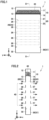
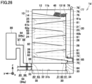
- Carbon dioxide capturing apparatus 1 comprises a storage unit 10, an adsorption unit 20, and a collection unit 30.
- Storage unit 10 accommodates an adsorbent 40.
- Adsorbent 40 can adsorb carbon dioxide.
- Adsorbent 40 is a solid adsorbent carrying amine, zeolite, silica gel, diatomite, alumina, or activated carbon for example.
- adsorbent 40 has a spherical shape or a cylindrical shape for example.
- Figs. 1 to 6 show adsorbent 40 darker as adsorbent 40 adsorbs more carbon dioxide.
- Storage unit 10 is disposed above adsorption unit 20.
- Storage unit 10 includes a storage body 11 and a valve 14. Inside storage body 11 is formed a storage space 12 to store adsorbent 40. Storage body 11 (specifically, a bottom portion of storage body 11) is provided with an opening 13. Opening 13 communicates with storage space 12 and an adsorption space of adsorption unit 20. Valve 14 opens and closes opening 13. When valve 14 closes opening 13, adsorbent 40 is stored in storage unit 10. When valve 14 opens opening 13, adsorbent 40 falls toward the adsorption space of adsorption unit 20 by the self-weight of adsorbent 40.
- Adsorption unit 20 is disposed between storage unit 10 and collection unit 30.
- adsorbent 40 comes into contact with a gas 43 containing carbon dioxide and adsorbs the carbon dioxide contained in gas 43.
- gas 43 is not particularly limited insofar as it is a gas containing carbon dioxide, it is for example air.
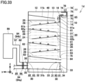
- adsorption unit 20 includes a front wall 21, a rear wall 22 opposite to front wall 21, a side wall 23, and a side wall 24 opposite to side wall 23.
- Side walls 23 and 24 are each connected to front wall 21 and rear wall 22.
- An adsorption space 25 is formed inside adsorption unit 20.
- Front wall 21, rear wall 22, and side walls 23 and 24 define adsorption space 25.
- front wall 21 has a width larger than that of each of side walls 23 and 24.
- Rear wall 22 has a width larger than that of each of side walls 23 and 24.
- the width of front wall 21 is a length of front wall 21 in a direction (a y direction) perpendicular to a direction of falling through adsorption unit 20 (i.e., a - z direction).
- the width of rear wall 22 is a length of rear wall 22 in the direction (the y direction) perpendicular to the direction of falling through adsorption unit 20 (i.e., the - z direction).
- the width of side wall 23 is a length of side wall 23 in the direction (an x direction) perpendicular to the direction of falling through adsorption unit 20 (i.e., the - z direction).
- the width of side wall 24 is a length of side wall 24 in the direction (the x direction) perpendicular to the direction of falling through adsorption unit 20 (i.e., the - z direction).
- Adsorption unit 20 (specifically, front wall 21) is provided with an opening 26. Gas 43 containing carbon dioxide flows through opening 26 into adsorption space 25.
- opening 26 is an inlet for gas 43.
- Opening 26 has a width for example of 60% or more and 100% or less of the width of front wall 21. Opening 26 may have a width of 80% or more and 95% or less of the width of front wall 21.
- the width of opening 26 is a length of opening 26 in a direction (the y direction) perpendicular to the direction of falling through adsorption unit 20 (i.e., the - z direction). While in the present embodiment adsorption unit 20 is provided with a plurality of openings 26, adsorption unit 20 may be provided with at least one opening 26.
- Adsorption unit 20 (specifically, rear wall 22) is provided with an opening 27. Gas 43 flows out of adsorption space 25 through opening 27.
- opening 27 is an outlet for gas 43.
- Opening 27 has a width for example of 60% or more and 100% or less of the width of rear wall 22.
- the width of opening 27 is a length of opening 27 in a direction (the y direction) perpendicular to the direction of falling through adsorption unit 20 (i.e., the - z direction).
- adsorption unit 20 is provided with a plurality of openings 27, adsorption unit 20 may be provided with at least one opening 27. Opening 27 faces opening 26 for example in a direction (the x direction) perpendicular to the direction of falling through adsorption unit 20 (i.e., the - z direction).
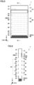
- Adsorbent 40 falls from storage unit 10 through adsorption space 25 toward collection unit 30 by the self-weight of adsorbent 40.
- Adsorbent 40 falls in a direction (or the - z direction), which is for example the direction of gravity.
- Gas 43 is introduced through opening 26 into adsorption space 25 in a direction (e.g., a + x direction) intersecting the direction in which adsorbent 40 falls (e.g., the - z direction).
- Adsorbent 40 in adsorption space 25 comes into contact with gas 43 and adsorbs carbon dioxide contained in gas 43. Gas 43 having carbon dioxide removed by adsorbent 40 flows out of adsorption space 25 through opening 27.
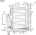
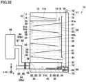
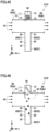
- carbon dioxide capturing apparatus 1 of a third exemplary variation of the present embodiment has one opening 28 provided at adsorption unit 20 through front wall 21. Opening 28 is larger than each of openings 26 and 27. Opening 28 functions as an inlet and an outlet for gas 43. Depending on the direction in which gas 43 flows, an upper portion of opening 28 may function as an inlet for gas 43 and a lower portion of opening 28 may function as an outlet for gas 43, or the lower portion of opening 28 may function as an inlet for gas 43 and the upper portion of opening 28 may function as an outlet for gas 43.
- Carbon dioxide capturing apparatus 1 of the third exemplary variation of the present embodiment is suitable for installation on a wall (not shown).
- carbon dioxide can be efficiently separated from adsorbent 40.
- Adsorbent 40 having carbon dioxide separated therefrom can be reused. Carbon dioxide can be captured more efficiently.
- carbon dioxide can be efficiently separated from adsorbent 40.
- Adsorbent 40 having carbon dioxide separated therefrom can be reused. Carbon dioxide can be captured more efficiently.
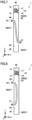
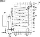
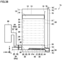
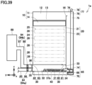
- duct 93 includes an upstream duct portion 93a and a downstream duct portion 93b.
- Gas 43 containing carbon dioxide flows from upstream duct portion 93a to downstream duct portion 93b.
- Carbon dioxide capturing apparatus 1f is disposed between upstream duct portion 93a and downstream duct portion 93b.
- Upstream duct portion 93a is disposed upstream of carbon dioxide capturing apparatus 1f in a direction in which gas 43 flows.
- Upstream duct portion 93a is connected to carbon dioxide capturing apparatus 1f and communicates with opening 26.
- Downstream duct portion 93b is disposed downstream of carbon dioxide capturing apparatus 1f in the direction in which gas 43 flows.
- Downstream duct portion 93b is connected to carbon dioxide capturing apparatus 1f and communicates with opening 27.
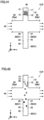
- valve 14 closes opening 13.
- adsorbent 40 is stored in storage unit 10.
- Valve 14 opens opening 13, as shown in Fig. 42 .
- adsorbent 40 falls toward adsorption space 25 of adsorption unit 20 by the self-weight of adsorbent 40.
- adsorbent 40 falls from storage unit 10 through adsorption space 25 toward collection unit 30 by the self-weight of adsorbent 40.
- Gas 43 containing carbon dioxide flows from upstream duct portion 93a to downstream duct portion 93b.
- Gas 43 is introduced through opening 26 into adsorption space 25 in a direction (e.g., the + x direction) intersecting the direction in which adsorbent 40 falls (e.g., the - z direction).
- Opening 26 is an inlet for gas 43.
- Adsorbent 40 in adsorption space 25 comes into contact with gas 43 and adsorbs carbon dioxide contained in gas 43.
- Gas 43 having carbon dioxide removed by adsorbent 40 flows out of adsorption space 25 through opening 27.
- Opening 27 is an outlet for gas 43.
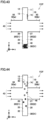
- Adsorbent 40 having adsorbed carbon dioxide contained in gas 43 falls from adsorption unit 20 toward collection unit 30 by the self-weight of adsorbent 40. As shown in Fig. 43 , as in the step shown in Figs. 5 and 6 according to the first embodiment, adsorbent 40 having adsorbed carbon dioxide passes through opening 33 and is accommodated in collection space 32 of collection unit 30. Adsorbent 40 having adsorbed carbon dioxide is collected in collection unit 30.
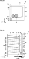
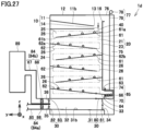
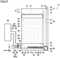
- adsorption unit 20 includes net 46 allowing gas 43 to pass therethrough and preventing adsorbent 40 from passing therethrough. Net 46 covers opening 27.
- valve 14 when valve 14 opens opening 13, valve 14 closes a portion of opening 26 that is an inlet for gas 43. Valve 14 stops a portion of a flow of gas 43 containing carbon dioxide. A negative pressure region 94 is created downstream of valve 14. A portion of adsorption space 25 becomes negative pressure region 94. Negative pressure region 94 is a region in which gas 43 is lower in pressure than it is in a region surrounding negative pressure region 94. Further, gas 43 flows at a slower velocity in negative pressure region 94 than it does in a region surrounding negative pressure region 94. This can prevent adsorbent 40 from being carried away by gas 43 and exiting adsorption unit 20 through opening 27.
- Carbon dioxide capturing apparatus 1f and air conditioning ventilation system 2f of the present embodiment have the following effects in addition to the effects of carbon dioxide capturing apparatus 1 and air conditioning ventilation system 2 of the first embodiment.
- adsorption unit 20 includes net 46 allowing gas 43 to pass therethrough and preventing adsorbent 40 from passing therethrough.
- Adsorption unit 20 is provided with an outlet (opening 27) through which gas 43 flows out of adsorption space 25. Net 46 covers the outlet.
- Net 46 can pass gas 43 having carbon dioxide removed by adsorbent 40 and prevent adsorbent 40 from being carried away by gas 43 and exiting adsorption unit 20 through the outlet (e.g., opening 27).
- the first valve (valve 14) stops a portion of a flow of gas 43 containing carbon dioxide. Negative pressure region 94 is created downstream of the first valve. Adsorbent 40 can be prevented from being carried away by gas 43 and exiting adsorption unit 20.
- Air conditioning ventilation system 2f of the present embodiment comprises carbon dioxide capturing apparatus 1f and duct 93 connected to carbon dioxide capturing apparatus If.
- Duct 93 communicates with an inlet (opening 26).
- Duct 93 that communicates with the inlet (opening 26) allows a flow of gas 43 flowing through duct 93 to be utilized to introduce gas 43 into adsorption space 25. Carbon dioxide contained in gas 43 can be captured more efficiently.
Landscapes
- Chemical & Material Sciences (AREA)
- Engineering & Computer Science (AREA)
- General Chemical & Material Sciences (AREA)
- Chemical Kinetics & Catalysis (AREA)
- Oil, Petroleum & Natural Gas (AREA)
- Analytical Chemistry (AREA)
- Mechanical Engineering (AREA)
- General Engineering & Computer Science (AREA)
- Combustion & Propulsion (AREA)
- Separation Of Gases By Adsorption (AREA)
- Carbon And Carbon Compounds (AREA)
- Solid-Sorbent Or Filter-Aiding Compositions (AREA)
- Treating Waste Gases (AREA)
- Ventilation (AREA)
Applications Claiming Priority (1)
| Application Number | Priority Date | Filing Date | Title |
|---|---|---|---|
| PCT/JP2022/022029 WO2023233495A1 (ja) | 2022-05-31 | 2022-05-31 | 二酸化炭素回収装置、空調換気システム及び二酸化炭素回収方法 |
Publications (1)
| Publication Number | Publication Date |
|---|---|
| EP4534178A1 true EP4534178A1 (en) | 2025-04-09 |
Family
ID=89025915
Family Applications (1)
| Application Number | Title | Priority Date | Filing Date |
|---|---|---|---|
| EP22944784.2A Pending EP4534178A1 (en) | 2022-05-31 | 2022-05-31 | Carbon dioxide recovery apparatus, air-conditioning and ventiliation system, and carbon dioxide recovery method |
Country Status (5)
| Country | Link |
|---|---|
| US (1) | US20250325937A1 (enExample) |
| EP (1) | EP4534178A1 (enExample) |
| JP (2) | JP7453474B1 (enExample) |
| CN (1) | CN119233857A (enExample) |
| WO (1) | WO2023233495A1 (enExample) |
Family Cites Families (11)
| Publication number | Priority date | Publication date | Assignee | Title |
|---|---|---|---|---|
| BE638542A (enExample) * | 1962-10-16 | |||
| JPS513369A (enExample) * | 1974-06-28 | 1976-01-12 | Mitsubishi Heavy Ind Ltd | |
| JPS536099B2 (enExample) * | 1974-12-28 | 1978-03-04 | ||
| JPS54152254U (enExample) * | 1978-04-15 | 1979-10-23 | ||
| JPS56150413A (en) * | 1980-04-23 | 1981-11-20 | Hitachi Ltd | Moving bed type adsorbent-packed layer |
| DE69737187T2 (de) * | 1996-10-09 | 2007-05-03 | Sumitomo Heavy Industries, Ltd. | Methode zur abgasbehandlung |
| JPH10174837A (ja) * | 1996-12-19 | 1998-06-30 | Babcock Hitachi Kk | 有害成分除去装置 |
| JP3965748B2 (ja) * | 1997-11-27 | 2007-08-29 | 石川島播磨重工業株式会社 | 活性炭吸着塔 |
| JP2006275487A (ja) * | 2005-03-30 | 2006-10-12 | Shimizu Corp | 炭酸ガス除去空調システム |
| WO2011137398A1 (en) * | 2010-04-30 | 2011-11-03 | Peter Eisenberger | System and method for carbon dioxide capture and sequestration |
| US9073005B2 (en) | 2011-06-09 | 2015-07-07 | Sri International | Falling microbead counter-flow process for separating gas mixtures |
-
2022
- 2022-05-31 WO PCT/JP2022/022029 patent/WO2023233495A1/ja not_active Ceased
- 2022-05-31 JP JP2023516101A patent/JP7453474B1/ja active Active
- 2022-05-31 US US18/868,788 patent/US20250325937A1/en active Pending
- 2022-05-31 EP EP22944784.2A patent/EP4534178A1/en active Pending
- 2022-05-31 CN CN202280096194.2A patent/CN119233857A/zh active Pending
-
2023
- 2023-11-28 JP JP2023200361A patent/JP2024039023A/ja active Pending
Also Published As
| Publication number | Publication date |
|---|---|
| CN119233857A (zh) | 2024-12-31 |
| JPWO2023233495A1 (enExample) | 2023-12-07 |
| US20250325937A1 (en) | 2025-10-23 |
| JP7453474B1 (ja) | 2024-03-19 |
| WO2023233495A1 (ja) | 2023-12-07 |
| JP2024039023A (ja) | 2024-03-21 |
Similar Documents
| Publication | Publication Date | Title |
|---|---|---|
| CN215610159U (zh) | 一种分离过喷漆雾的装置和具备该装置的漆雾分离系统 | |
| CN103480232B (zh) | 用于制铝厂的紧凑空气质量控制系统隔间 | |
| JP3460818B2 (ja) | 工業性粉塵除去装置 | |
| CN113490538A (zh) | 污染物捕集器和净化器 | |
| KR101702920B1 (ko) | 매립가스 메탄 직접 전환 기술을 적용한 매립 가스 전환 장치 | |
| WO2009145469A2 (ko) | 지하생활공간용 이동식 공기정화장치 | |
| EP4534178A1 (en) | Carbon dioxide recovery apparatus, air-conditioning and ventiliation system, and carbon dioxide recovery method | |
| KR20200141283A (ko) | 지하철 승강장의 슬림형 공기정화장치 | |
| US20130192467A1 (en) | Two stage dust collection trailer with hepa filtration | |
| CN108554633B (zh) | 一种高效静电除尘器 | |
| JP3107375B2 (ja) | オイルミスト捕集装置 | |
| CN110898600A (zh) | 一种轮毂锻压过程废气净化系统 | |
| JP2002282635A (ja) | バグフィルタおよびその運転方法 | |
| CN212662968U (zh) | 一种正压改两级风机负压式布袋除尘器 | |
| US4190014A (en) | Industrial dust collector cleaning system and method | |
| CN211513951U (zh) | 一种轮毂锻压过程废气净化系统 | |
| CN209885582U (zh) | 一种用于粉尘的废气处理设备 | |
| JP2007232438A (ja) | 試料採取車両 | |
| CN222228594U (zh) | 隧道排烟装置 | |
| CN212998890U (zh) | 移动除尘装置 | |
| KR20000054562A (ko) | 수막 집진장치에 의한 유해물질 제거 공조장치 | |
| CN215901169U (zh) | 一种联动脱硝设备 | |
| RU2781547C2 (ru) | Устройство и способ регулируемой подачи оксида алюминия | |
| CN116498529B (zh) | 一种纺织用空压机 | |
| CN119656853A (zh) | 一种烟风流毒害气体四位一体分区同步消除系统及方法 |
Legal Events
| Date | Code | Title | Description |
|---|---|---|---|
| STAA | Information on the status of an ep patent application or granted ep patent |
Free format text: STATUS: THE INTERNATIONAL PUBLICATION HAS BEEN MADE |
|
| PUAI | Public reference made under article 153(3) epc to a published international application that has entered the european phase |
Free format text: ORIGINAL CODE: 0009012 |
|
| STAA | Information on the status of an ep patent application or granted ep patent |
Free format text: STATUS: REQUEST FOR EXAMINATION WAS MADE |
|
| 17P | Request for examination filed |
Effective date: 20241121 |
|
| AK | Designated contracting states |
Kind code of ref document: A1 Designated state(s): AL AT BE BG CH CY CZ DE DK EE ES FI FR GB GR HR HU IE IS IT LI LT LU LV MC MK MT NL NO PL PT RO RS SE SI SK SM TR |
|
| DAV | Request for validation of the european patent (deleted) | ||
| DAX | Request for extension of the european patent (deleted) |