WO2023228551A1 - 接続端子、ステータ組立体、電動機及びステータ組立体の製造方法 - Google Patents
接続端子、ステータ組立体、電動機及びステータ組立体の製造方法 Download PDFInfo
- Publication number
- WO2023228551A1 WO2023228551A1 PCT/JP2023/012454 JP2023012454W WO2023228551A1 WO 2023228551 A1 WO2023228551 A1 WO 2023228551A1 JP 2023012454 W JP2023012454 W JP 2023012454W WO 2023228551 A1 WO2023228551 A1 WO 2023228551A1
- Authority
- WO
- WIPO (PCT)
- Prior art keywords
- connection
- pin
- stator
- connection terminal
- winding
- Prior art date
- Legal status (The legal status is an assumption and is not a legal conclusion. Google has not performed a legal analysis and makes no representation as to the accuracy of the status listed.)
- Ceased
Links
Images

Classifications
-
- H—ELECTRICITY
- H02—GENERATION; CONVERSION OR DISTRIBUTION OF ELECTRIC POWER
- H02K—DYNAMO-ELECTRIC MACHINES
- H02K15/00—Processes or apparatus specially adapted for manufacturing, assembling, maintaining or repairing of dynamo-electric machines
- H02K15/04—Processes or apparatus specially adapted for manufacturing, assembling, maintaining or repairing of dynamo-electric machines of windings prior to their mounting into the machines
-
- H—ELECTRICITY
- H02—GENERATION; CONVERSION OR DISTRIBUTION OF ELECTRIC POWER
- H02K—DYNAMO-ELECTRIC MACHINES
- H02K21/00—Synchronous motors having permanent magnets; Synchronous generators having permanent magnets
- H02K21/12—Synchronous motors having permanent magnets; Synchronous generators having permanent magnets with stationary armatures and rotating magnets
-
- H—ELECTRICITY
- H02—GENERATION; CONVERSION OR DISTRIBUTION OF ELECTRIC POWER
- H02K—DYNAMO-ELECTRIC MACHINES
- H02K3/00—Details of windings
- H02K3/46—Fastening of windings on the stator or rotor structure
- H02K3/50—Fastening of winding heads, equalising connectors, or connections thereto
Definitions
- the present disclosure relates to a connection terminal used in an electric motor, a stator assembly including the connection terminal, an electric motor including the stator assembly, and a method for manufacturing the stator assembly.
- Electric motors are used in various electrical equipment such as household equipment or industrial equipment.
- electric motors commutator motors that use brushes and brushless motors that do not use brushes are known.
- a brushless motor includes, for example, a rotor, a stator, and a circuit board (see, for example, Patent Document 1).
- the rotor has magnets.
- the stator includes a stator core and a winding wound around the stator core via an insulator. Circuit components for generating current to be supplied to the windings of the stator are mounted on the circuit board.
- the stator and circuit board are combined as a stator assembly.
- the windings of the stator and the circuit board are electrically connected.
- a technique is known in which a connection pin is fixed to an insulator of a stator, and the connection pin is used to electrically connect a winding of the stator to a circuit board. Specifically, the ends of the windings are tied around the connection pins and soldered, the connection pins are inserted into through holes of the circuit board, and the connection pins and the circuit board are soldered. Thereby, the connection pin and the circuit board can be electrically and mechanically connected. Furthermore, the stator windings and the circuit board can be electrically connected via the connection pins, and the stator and the circuit board can be combined.
- connection pin may fall diagonally due to stress when the end of the winding is tied around the connection pin or thermal stress when soldering the winding tied around the connection pin. If the connecting pin falls diagonally, even if the connecting pin is to be inserted into the through hole of the circuit board, it cannot be inserted reliably. This causes a wiring problem. Therefore, it is conceivable to provide a separate process for correcting fallen connection pins. However, when such a step is provided, productivity decreases and production costs increase.
- the stator when the stator core is divided into a plurality of core blocks, the stator is constituted by a plurality of intermediate assemblies arranged in a cylindrical shape.
- Each intermediate assembly includes a core block, a winding wound around the core block through an insulator, and a pair of connection pins held by the insulator.
- the starting end of the winding wire is tied to one of the pair of connection pins.
- the end of the winding wire is tied to the other of the pair of connection pins.
- each of the plurality of intermediate assemblies is provided with a pair of connection pins.
- connection pins are provided depending on the number of divided core blocks. Therefore, even if one of the plurality of pairs of connecting pins falls down, the plurality of pairs of connecting pins cannot be inserted into the through holes of the circuit board. As a result, the stator and circuit board cannot be combined. When the stator core is divided into a plurality of core blocks in this way, the connection pins tend to fall down.
- connection pins tend to fall down. Furthermore, as the number of stator slots increases, the number of connection pins also increases. Therefore, as the number of slots in the stator increases, there is a greater risk that the connection pins will fall and the stator and circuit board will not be able to be combined.
- An object of the present disclosure is to provide a connection terminal that can suppress collapse of connection pins due to stress or thermal stress, a stator assembly including the connection terminal, an electric motor including the stator assembly, and a method for manufacturing the stator assembly. do.
- connection terminal to which a winding disposed in a slot of a stator core of an electric motor is connected, the terminal to which one end of the winding is connected.
- the winding device has a first connection pin, a second connection pin to which the other end of the winding is connected, and a connection portion that connects the first connection pin and the second connection pin.
- connection terminal is formed of a metal plate, and a cut portion having a width less than the thickness of the metal plate is provided at a connection portion of the connection portion with the first connection pin and the second connection pin. It is preferable that
- the direction in which the first connecting pin and the second connecting pin extend is defined as the width direction, and a groove extending throughout the width direction of the connecting portion is formed on the surface of the metal plate in the connecting portion. is preferred.
- connection terminal further includes an extension that is located between the first connection pin and the second connection pin and extends from the connecting portion in the longitudinal direction of the first connection pin when the connection terminal is viewed from the front. It is preferable to have an existing part.
- the connection terminal When the connection terminal is viewed from the side, the first connection pin, the second connection pin, and the extension portion are arranged so that the first plane including the first connection pin and the second connection pin and the extension portion are connected to each other. It is preferable that the second plane including the portion be located at a position shifted in the front-rear direction in a direction intersecting the direction in which the first connecting pin and the second connecting pin extend.
- the extending portion protrudes from the connecting portion in a direction opposite to the tip end of the first connecting pin, then makes a U-turn and extends toward the tip end of the first connecting pin. It is preferable.
- the first connection pin has a first main body portion extending in one direction and a first connection portion to which one end of the winding wire is connected.
- the second connection pin has a second main body portion extending in the one direction, and a second connection portion to which the other end of the winding is connected.
- the first wire connection portion protrudes from an outer side of the first main body portion and is bent inward to face the first main body portion.
- the second wire connection portion protrudes from the outer side of the second main body and is bent inward to face the second main body.
- the stator core is divided into a plurality of core blocks, and the connection terminal is provided corresponding to each of the plurality of core blocks.
- stator assembly includes a stator core, a winding disposed in a slot of the stator core, a connection terminal to which the winding is connected, and a circuit board to which the connection terminal is connected.
- the connection terminal has a first connection pin to which one end of the winding is connected, and a second connection pin to which the other end of the winding is connected, and the second connection at the first connection pin
- a protrusion whose distal end surface is a fractured surface is formed on a portion of the end surface on the pin side, and a protrusion whose distal end surface is a fractured surface is formed on a portion of the end surface of the second connecting pin on the first connecting pin side. is formed.
- stator core is constituted by a plurality of core blocks, and that the connection terminal is provided corresponding to each of the plurality of core blocks.
- connection terminal is held by an insulator fixed to the plurality of core blocks.
- One aspect of the electric motor according to the present disclosure includes the stator assembly described above and a rotor facing the stator assembly.
- One aspect of the method for manufacturing a stator assembly includes a step of preparing a stator having connection terminals, a stator core, and windings, and connecting the stator to the circuit board by connecting the connection terminals to the circuit board.
- the connection terminal includes a first connection pin to which one end of the winding is connected, a second connection pin to which the other end of the winding is connected, and the first connection pin and the second connection. and a connecting portion that connects the stator to the circuit board, and in the step of connecting the stator to the circuit board, electrically and mechanically connects the first connection pin and the second connection pin of the connection terminal to the circuit board.
- the method for manufacturing a stator assembly includes the step of cutting the connecting portion of the connecting terminal after connecting the connecting terminal to the circuit board.
- connection terminal is further located between the first connection pin and the second connection pin, and extends from the connection portion in the longitudinal direction of the first connection pin and the second connection pin. It has an extension part.
- a notch is formed at an end of the circuit board.
- connection portion of the connection terminal is cut after one end of the winding is connected to the first connection pin and the other end of the winding is connected to the second connection pin.
- the stator core is composed of a plurality of core blocks, and the connection terminal is provided corresponding to each of the plurality of core blocks, and one core block, one connection terminal, and one connection terminal are provided.
- the windings constitute an intermediate assembly, and the stator is constructed by arranging a plurality of intermediate assemblies in a cylindrical shape, and in the stator, each of the plurality of intermediate assemblies has a It is preferable that the connection terminal protrudes toward one direction of the cylinder axis of the stator.
- connection pin from collapsing due to stress or thermal stress.
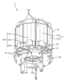
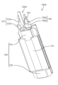
- FIG. 1 is a sectional view of an electric motor according to an embodiment taken along a plane passing through a rotation axis.
- FIG. 2 is a sectional view of the electric motor according to the embodiment taken along a plane perpendicular to the rotation axis.
- FIG. 3 is an exploded perspective view of the electric motor according to the embodiment, viewed diagonally from above.
- FIG. 4 is an exploded perspective view of the electric motor according to the embodiment as viewed diagonally from below.
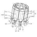
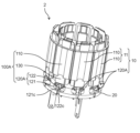
- FIG. 5 is a perspective view of the stator assembly according to the embodiment.
- FIG. 6 is a cross-sectional view of the stator assembly according to the embodiment.
- FIG. 7 is a perspective view of an intermediate assembly in a stator according to an embodiment.
- FIG. 8 is an exploded perspective view of the intermediate assembly in the stator according to the embodiment.
- FIG. 9 is a perspective view of the connection terminal according to the embodiment when viewed from the front side.
- FIG. 10 is a perspective view of the connection terminal according to the embodiment when viewed from the back side.
- FIG. 11A is a front view of the connection terminal according to the embodiment.
- FIG. 11B is an enlarged side view of the main part of the connection terminal according to the embodiment.
- FIG. 12 is an enlarged perspective view showing a part of the connection terminal according to the embodiment.
- FIG. 13A is a diagram for explaining a step of preparing an intermediate assembly in the method of manufacturing a stator assembly according to the embodiment.
- FIG. 13A is a diagram for explaining a step of preparing an intermediate assembly in the method of manufacturing a stator assembly according to the embodiment.
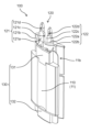
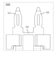
- FIG. 13B is a diagram for explaining a step of preparing a stator and a circuit board in the method of manufacturing a stator assembly according to the embodiment.
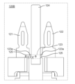
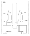
- FIG. 13C is a diagram for explaining the process of connecting the stator and the circuit board in the method for manufacturing a stator assembly according to the embodiment.
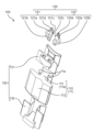
- FIG. 13D is a diagram illustrating a step of cutting the connection portion of the connection terminal in the method of manufacturing the stator assembly according to the embodiment.
- FIG. 14 is a photograph showing the first protrusion formed on the first connecting pin after cutting the connecting portion of the connecting terminal.
- FIG. 15A is an enlarged front view of a connection terminal according to Modification 1.
- FIG. 15B is a cross-sectional view of the connection terminal according to Modification 1 taken along line BB in FIG. 15A.
- FIG. 16 is an enlarged front view of a connection terminal according to modification 2.
- FIG. 17 is an enlarged front view of a connection terminal according to modification 3.
- each figure is a schematic diagram and is not necessarily strictly illustrated.
- components that are substantially the same as those in other figures are denoted by the same reference numerals, and overlapping explanations will be omitted or simplified.
- the terms “upper” and “lower” do not necessarily refer to the upper direction (vertically upward) and the downward direction (vertically downward) in absolute spatial recognition.
- FIG. 1 is a cross-sectional view of the electric motor 1 according to the embodiment taken along a plane passing through the rotating shaft 31.
- FIG. 2 is a cross-sectional view of the electric motor 1 according to the embodiment taken along a plane perpendicular to the rotating shaft 31.
- FIG. FIG. 2 shows a cross section taken along line II-II in FIG.
- FIG. 3 is an exploded perspective view of the electric motor 1 according to the embodiment, viewed diagonally from above.
- FIG. 4 is an exploded perspective view of the electric motor 1 according to the embodiment, viewed diagonally from below. In FIGS. 3 and 4, the winding 12 is omitted.
- FIG. 5 is a perspective view of the stator assembly 2 according to the embodiment.
- FIG. 6 is a sectional view of the stator assembly 2 according to the embodiment.
- the electric motor 1 includes a stator 10, a circuit board 20, and a rotor 30 having a rotating shaft 31. As shown in FIG. 5, stator 10 and circuit board 20 are combined as stator assembly 2. As shown in FIG.
- the electric motor 1 further includes a first bearing 41, a second bearing 42, a first bracket 51, and a second bracket 52.
- the electric motor 1 is a brushless motor.
- the electric motor 1 can be used, for example, as a blower motor or a drive motor that is small and requires high output.
- the size of the electric motor 1 is, for example, a diameter of 50 mm or less.
- the electric motor 1 is an inner rotor type motor in which a rotor 30 is disposed inside a stator 10. That is, the stator 10 is arranged so as to surround the rotor 30. Therefore, the rotor 30 rotates around the axis C of the rotating shaft 31 inside the stator 10.
- a stator (stator) 10 is disposed facing the rotor 30 with a small air gap therebetween. Specifically, the stator 10 is arranged so as to surround the rotor core 32 of the rotor 30.
- the stator 10 generates magnetic force that acts on the rotor 30.
- the stator 10 has a configuration in which a plurality of N poles and S poles are alternately and repeatedly present along the rotation direction so as to generate magnetic flux in the air gap surface between the rotor core 32 and the rotor 30. ing.
- the stator 10 and the rotor 30 constitute a magnetic circuit.
- the stator 10 constitutes an armature.
- the stator 10 includes a stator core 11 (stator core) and a winding 12 arranged on the stator core 11.
- the winding 12 is a winding coil wound around the stator core 11.
- the stator core 11 has a plurality of teeth 11a that protrude toward the rotor 30. Specifically, the plurality of teeth 11a extend radially in a direction (radial direction) orthogonal to the axis C of the rotating shaft 31. The plurality of teeth 11a are arranged at equal intervals in the circumferential direction while forming slots 11b between two adjacent teeth 11a. Stator core 11 has nine teeth 11a. In other words, the number of slots in the stator 10 is nine.
- Winding 12 is arranged in the slot 11b of the stator core 11.
- Winding 12 is a stator coil that is an armature winding of stator 10 .
- the winding 12 is a concentrated winding coil wound around each tooth 11a.
- the winding 12 is a three-phase winding so that the rotor 30 can be rotated as a three-phase synchronous motor.
- the winding 12 is composed of unit coils for each of three phases, U-phase, V-phase, and W-phase, which are electrically different in phase by 120 degrees from each other. That is, the winding 12 wound around each tooth 11a is energized and driven by three-phase alternating current that is energized in units of U phase, V phase, and W phase. Thereby, the main magnetic flux of the stator 10 is generated in each tooth 11a.
- each tooth 11a is a magnetic pole tooth.
- Each tooth 11a is an electromagnet that generates magnetic force when current flows through the winding 12.
- the stator core 11 is divided into a plurality of core blocks 110 (divided cores). That is, the stator core 11 of the stator 10 is composed of a plurality of core blocks 110.
- the plurality of core blocks 110 are arranged in an annular shape as a whole. Specifically, nine core blocks 110 are arranged in an annular shape. Two adjacent core blocks 110 are connected to each other. That is, the stator core 11 is configured by connecting a plurality of core blocks in an annular shape. A winding 12 is wound around each of the plurality of core blocks 110. Since stator 10 has nine core blocks 110, nine windings 12 are used.
- one core block 110 and one winding 12 constitute an intermediate assembly 100. Therefore, the stator 10 is made up of nine intermediate assemblies 100.
- Intermediate assembly 100 is an intermediate part used when manufacturing stator assembly 2. The detailed configuration of the intermediate assembly 100 will be described later.
- the circuit board 20 is, for example, a printed circuit board (PCB) on which wiring made of a conductive material such as copper is formed in a predetermined pattern.
- PCB printed circuit board
- a resin material such as a glass epoxy substrate, a metal material such as an aluminum alloy substrate, or the like can be used.
- a plurality of electronic components (not shown) for generating a current to be supplied to the winding 12 of the stator 10 are mounted on the circuit board 20.
- the plurality of electronic components constitute a circuit that generates three-phase alternating current of U phase, V phase, and W phase.
- the circuit board 20 is provided with a through hole 21.
- the connection terminal 120 of the intermediate assembly 100 corresponding to the core block 110 is connected to the through hole 21.
- the connection terminal 120 is a connection terminal to which the winding 12 of the stator 10 is connected.
- a connecting terminal 120 to which the winding 12 is connected is inserted into the through hole 21 .
- the connection terminal 120 and the circuit board 20 are connected.
- the first connecting pin 121 and the second connecting pin 122 of the connecting terminal 120 are inserted into the through hole 21.
- the circuit board 20 is a wiring board to which the windings 12 are connected via the connection terminals 120.
- the circuit board 20 is provided with a plurality of through holes 21 . Specifically, at least twice the number of through holes 21 as the number of intermediate assemblies 100 (that is, the number of core blocks 110) are provided.
- the inner circumferential surface of each through hole 21 is coated with a conductive film that is electrically connected to wiring formed on the main surface of the circuit board 20 .
- the conductive film is, for example, copper plating. The detailed configuration of the connection terminal 120 will be described later.
- the rotor (rotor) 30 is rotated by the magnetic force generated by the stator 10.
- the rotor 30 has a structure in which a plurality of north poles and south poles are alternately and repeatedly present along the rotation direction. Thereby, the rotor 30 generates a magnetic force that acts on the stator 10.
- the direction of the magnetic flux generated by the rotor 30 is a direction perpendicular to the direction in which the axis C included in the rotating shaft 31 extends (axial direction). That is, the direction of the magnetic flux generated by the rotor 30 is the radial direction.
- the rotor 30 includes a rotating shaft 31, a rotor core 32, and a permanent magnet 33.
- the rotor 30 is an interior permanent magnet (IPM) rotor in which a permanent magnet 33 is embedded in a rotor core 32. Therefore, electric motor 1 is an IPM motor.
- the rotating shaft 31 is an elongated shaft.
- the rotating shaft 31 is, for example, a metal rod.
- the rotating shaft 31 is fixed to a rotor core 32. Specifically, the rotating shaft 31 is inserted into a through hole provided at the center of the rotor core 32 and fixed to the rotor core 32 so as to extend on both sides of the rotor core 32 in the direction in which the axis C extends. ing.
- the rotor core 32 is a laminate in which a plurality of steel plates are laminated in the direction in which the axis C of the rotating shaft 31 extends (axial direction).
- Each of the plurality of steel plates is, for example, a punched electromagnetic steel plate formed into a predetermined shape.
- the plurality of steel plates are fixed to each other, for example, by caulking.
- the permanent magnet 33 is inserted into a magnet insertion hole 32a provided in the rotor core 32.
- Six magnet insertion holes 32a are provided in the rotor core 32 at equal intervals in the circumferential direction. Therefore, the rotor 30 has six permanent magnets 33 arranged at equal intervals in the circumferential direction. That is, the number of poles of the electric motor 1 is six.
- Permanent magnet 33 is a sintered magnet. However, the permanent magnet 33 may be a bonded magnet.
- the rotating shaft 31 of the rotor 30 is provided with a first bearing 41 and a second bearing 42 that rotatably hold the rotating shaft 31.
- the first bearing 41 and the second bearing 42 are bearings that rotatably hold the rotating shaft 31.
- the first bearing 41 supports a portion of the rotating shaft 31 that protrudes from one side of the rotor core 32 .
- the second bearing 42 supports a portion of the rotating shaft 31 that protrudes from the other side of the rotor core 32 .
- the first bearing 41 and the second bearing 42 are, for example, ball bearings. However, it is not limited to this.
- the first bracket 51 holds the first bearing 41. Specifically, the first bearing 41 is fixed to a recess provided in the first bracket 51.
- the second bracket 52 holds the second bearing 42. Specifically, the second bearing 42 is fixed to a recess provided in the second bracket 52.
- the first bracket 51 and the second bracket 52 are made of metal or resin material.
- the first bracket 51 and the second bracket 52 constitute the outer shell of the electric motor 1.
- the first bracket 51 is a bottomed cylindrical frame (housing) having an opening.
- the second bracket 52 is a bottom plate that closes the opening of the first bracket 51.
- the first bracket 51 is a metal frame made of metal.
- the second bracket 52 is a resin plate made of resin.
- the rotating shaft 31 of the rotor 30 passes through the first bracket 51. A portion of the rotating shaft 31 protrudes from the first bracket 51 to the outside. Although not shown, a load such as a rotating fan is attached to a portion of the rotating shaft 31 that protrudes from the first bracket 51 to the outside. That is, the portion of the rotating shaft 31 that protrudes from the first bracket 51 is an output shaft.
- stator 10 stator core 11
- magnetic flux directed from the stator 10 to the rotor 30 is generated.
- magnetic flux is generated from each of the teeth 11a of the stator core 11 of the stator 10 toward the rotor core 32 of the rotor 30.
- a magnetic flux passing through the stator 10 is generated by the permanent magnet 33 embedded in the rotor core 32.
- the magnetic force generated by the interaction between the magnetic flux generated by the stator 10 and the magnetic flux generated from the permanent magnets 33 of the rotor 30 becomes a torque that rotates the rotor 30. This causes the rotor 30 to rotate.
- FIG. 7 is a perspective view of the intermediate assembly 100 in the stator 10 according to the embodiment.
- FIG. 8 is an exploded perspective view of the intermediate assembly 100 in the stator 10 according to the embodiment. In FIGS. 7 and 8, the winding 12 is omitted.
- the stator 10 is constructed by arranging a plurality of intermediate assemblies 100 in a cylindrical shape. Specifically, the plurality of intermediate assemblies 100 are arranged in a cylindrical shape.
- the stator core 11 in the stator 10 is composed of a plurality of core blocks 110. As shown in FIG. 2, the plurality of core blocks 110 are connected to form an annular shape as a whole.
- a core block 110 is provided for each intermediate assembly 100.
- a winding 12 in the stator 10 is also provided for each intermediate assembly 100.
- Connection terminals 120 are provided corresponding to each of the plurality of core blocks 110. That is, a connection terminal 120 is provided for each intermediate assembly 100.
- each of the plurality of intermediate assemblies 100 includes one core block 110, one winding 12 (not shown in FIGS. 7 and 8), and one connection terminal. 120. Additionally, each intermediate assembly 100 includes an insulator 130.
- the insulator 130 includes a first insulator 131 and a second insulator 132, which are a pair of insulators. Specifically, the insulator 130 is separated into a first insulator 131 and a second insulator 132, which are separate bodies.
- the core block 110 has teeth portions 111 and yoke portions 112. Teeth portion 111 is teeth 11a of stator core 11 shown in FIG.
- the teeth portion 111 is formed inside the yoke portion 112. Teeth portion 111 extends from yoke portion 112 toward the center of stator core 11 . Specifically, the teeth portion 111 extends from the yoke portion 112 toward the rotating shaft 31. That is, the teeth portion 111 extends so as to protrude inward in the radial direction of the stator 10.
- the tooth portion 111 has an extending portion that extends from the tip portion on the inner peripheral side of the tooth portion 111 to both sides in the circumferential direction. Each of the pair of extending portions is formed to protrude along the circumferential direction from the tip portion on the inner peripheral side of the tooth portion 111 . As shown in FIG. 2, in two adjacent core blocks 110, there is a gap ( slot opening).
- a slot 11b for arranging the winding 12 is formed between two adjacent teeth portions 111. That is, in each intermediate assembly 100, the slot 11b is a space area on the side of the tooth portion 111.
- the winding 12 is wound around the teeth portion 111. Specifically, the winding 12 is wound around the teeth 111 via an insulator 130.
- the yoke portion 112 is a back yoke formed on the outside of the teeth portion 111.
- Yoke portion 112 extends along the circumferential direction of stator core 11 .
- the yoke portion 112 extends along the circumferential direction (rotation direction of the rotating shaft 31) centered on the axis C of the rotating shaft 31.
- two adjacent yoke portions 112 are connected with their circumferential end surfaces abutting each other.
- the nine yoke parts 112 are arranged along the circumferential direction of a circle centered on the axis C of the rotating shaft 31.
- the nine yoke parts 112 are connected to form an annular shape as a whole.
- the core block 110 is constructed by laminating multiple steel plates. Specifically, the core block 110 is a laminate in which a plurality of punched electromagnetic steel sheets are laminated along the direction in which the axis C of the rotating shaft 31 extends. Each of the plurality of electromagnetic steel plates is fixed to each other, for example, by caulking.
- connection terminals 120 are provided corresponding to each of the plurality of core blocks 110. As shown in FIG. 7, the connection terminal 120 is held by an insulator 130 fixed to the core block 110. The connection terminal 120 is fixed to the first insulator 131 of the first insulator 131 and the second insulator 132. Specifically, the connection terminal 120 is fixed to the first insulator 131 by partially embedding the connection terminal 120 in the insulator 130. The connection terminal 120 is fixed to the first insulator 131 so as to protrude toward one side of the cylindrical axis direction of the stator 10 (the axial direction of the rotating shaft 31). The connection terminal 120 and the first insulator 131 can be integrally formed, for example, by insert molding.
- connection terminal 120 is a metal terminal made of a metal material.
- the connection terminal 120 is made of a copper alloy.
- the connection terminal 120 is made of brass. Expressed in another way, the connection terminal 120 is constituted by a metal plate.
- the connection terminal 120 has a first connection pin 121 and a second connection pin 122 as a pair of connection pins.
- the first connecting pin 121 and the second connecting pin 122 are not in contact with each other and are separated.
- the first connecting pin 121 and the second connecting pin 122 are made of metal plates.
- the first connecting pin 121 and the second connecting pin 122 have a symmetrical shape.
- the winding 12 is connected to the connection terminal 120 in each intermediate assembly 100. Specifically, one end of the winding 12 is connected to the first connection pin 121 . The other end of the winding 12 is connected to the second connection pin 122 . As an example, the first end of the winding 12 is connected to the first connection pin 121 as one end of the winding 12 . The other end of the winding 12 is connected to the second connection pin 122 .
- the first connection pin 121 has a first body portion 121a extending in one direction and a first connection portion 121b to which one end of the winding 12 is connected.
- the first connection portion 121b protrudes from the outer side of the first body portion 121a and is bent inward to face the first body portion 121a.
- one end of the winding 12 is tied to the first connection part 121b, and the first connection part 121b and the winding 12 are connected by, for example, fusing. Connect by.
- the method of connecting the first connection portion 121b and the winding 12 is not limited to fusing, and may be soldering.
- the second connection pin 122 has a second main body portion 122a extending in one direction and a second connection portion 122b to which the other end of the winding 12 is connected.
- the second connection portion 122b protrudes from the outer side of the second main body portion 122a and is bent inward to face the second main body portion 122a.
- one end of the winding 12 is tied to the second connection part 122b, and the second connection part 122b and the winding 12 are connected by, for example, a fuse. connection by ging.
- the method of connecting the second wire connection portion 122b and the winding 12 is not limited to fusing, and may be soldering.
- connection terminal 120 is connected to the circuit board 20. Specifically, the first connecting pin 121 and the second connecting pin 122 of the connecting terminal 120 are inserted into the through hole 21 of the circuit board 20. More specifically, the first body portion 121a of the first connecting pin 121 and the second body portion 122a of the second connecting pin 122 are inserted into the through hole 21.
- the first connecting pin 121 and the second connecting pin 122 are press-fitted into the through hole 21 of the circuit board 20. Specifically, the first body portion 121a of the first connection pin 121 and the second body portion 122a of the second connection pin 122 are press-fitted into the through hole 21 of the circuit board 20. That is, the first main body part 121a of the first connecting pin 121 and the second main body part 122a of the second connecting pin 122 are pushed into the through hole 21 and fitted into the through hole 21. Thereby, the first connection pin 121 and the second connection pin 122 are fixed to the circuit board 20.
- the first connecting pin 121 and the second connecting pin 122 are mechanically connected to the circuit board 20 by being press-fitted into the through hole 21 of the circuit board 20.
- the first connection pin 121 and the second connection pin 122 are electrically connected to the wiring of the circuit board 20 via a conductive film formed on the inner peripheral surface of the through hole 21 . Thereby, the first connection pin 121 and the second connection pin 122 can be electrically and mechanically connected to the circuit board 20 without soldering.
- a first protrusion 121c whose tip end surface is a broken surface is formed on a part of the end surface of the first connecting pin 121 on the second connecting pin 122 side. Specifically, the first protrusion 121c is formed on the side end surface of the thick portion of the first body portion 121a of the first connection pin 121.
- a second protrusion 122c whose tip end surface is a broken surface is formed on a part of the end surface of the second connection pin 122 on the first connection pin 121 side. Specifically, the second protrusion 122c is formed on the side end surface of the thick portion of the second body portion 122a of the second connection pin 122. The first protrusion 121c and the second protrusion 122c are formed at positions facing each other.
- the first protrusion 121c of the first connecting pin 121 and the second protrusion 122c of the second connecting pin 122 cut the connecting portion that connects the first connecting pin 121 and the second connecting pin 122. Formed when removed.
- the first protrusion 121c and the second protrusion 122c are cutting marks.
- the fractured surface of the first protrusion 121c and the fractured surface of the second protrusion 122c are cut surfaces formed when the connecting portion is cut. Therefore, the surface roughness of the fractured surface of the first projection 121c and the surface roughness of the fractured surface of the second projection 122c are rougher than the surface roughness of the metal plate forming the connection terminal 120.
- the first connecting pin 121 has a direction in which the first connecting pin 121 is press-fitted into the through hole 21 of the circuit board 20 (the press-fitting direction of the first connecting pin 121).
- An extending first slit 121d is formed.
- the first slit 121d is formed in the first body portion 121a of the first connection pin 121.
- the first slit 121d is formed at the center of the first connection pin 121 in the width direction.
- the first slit 121d is formed in a straight line with a substantially constant width.
- a second slit 122d is formed in the second connecting pin 122 and extends along the direction in which the second connecting pin 122 is press-fitted into the through hole 21 of the circuit board 20 (the press-fitting direction of the second connecting pin 122). has been done.
- the second slit 122d is formed in the second body portion 122a of the second connection pin 122.
- the second slit 122d is formed at the center of the second connection pin 122 in the width direction.
- the second slit 122d is formed in a straight line with a substantially constant width.
- the first connecting pin 121 and the second connecting pin 122 are press-fitted into the through hole 21. Therefore, the portion of the first connection pin 121 in which the first slit 121d is formed is a contact portion that comes into contact with the inner surface of the through hole 21.
- the portion of the second connection pin 122 in which the second slit 122d is formed is a contact portion that comes into contact with the inner surface of the through hole 21.
- the insulator 130 has a frame-shaped frame portion around which the winding 12 is wound. Specifically, the frame portion of the insulator 130 is formed so as to surround at least the body portion of the teeth portion 111 (teeth 11a).
- the insulator 130 is, for example, a resin molded product made of an insulating resin material.
- the insulator 130 is fixed to the core block 110. Specifically, the first insulator 131 is fixed to one end of the core block 110. The second insulator 132 is fixed to the other end of the core block 110. The first insulator 131 and the second insulator 132 are arranged to sandwich the teeth portion 111 of the core block 110 from the cylindrical axis direction of the stator 10 .
- stator 10 is configured as shown in FIG. 5.
- a stator 10 composed of a plurality of intermediate assemblies 100 is connected to a circuit board 20.
- a stator assembly 2 is constructed in which the stator 10, which is composed of a plurality of intermediate assemblies 100, and the circuit board 20 are combined.
- each connection terminal 120 of the plurality of intermediate assemblies 100 constituting the stator 10 is connected to the circuit board 20.
- the connecting terminal 120 instead of using the connecting terminal 120 in which the first connecting pin 121 and the second connecting pin 122 are separated, the first connecting pin 121 and the second connecting pin 122 are connected as described below.
- a connection terminal 120A is used.
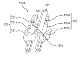
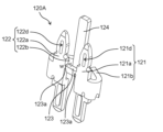
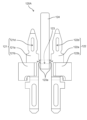
- FIG. 9 is a perspective view of the connection terminal 120A according to the embodiment when viewed from the front side.
- FIG. 10 is a perspective view of the connection terminal 120A according to the embodiment when viewed from the back side.
- FIG. 11A is a front view of the connection terminal 120A according to the embodiment.
- FIG. 11B is an enlarged side view of a main part of the connection terminal 120A according to the embodiment.
- FIG. 12 is an enlarged perspective view showing a part of the connection terminal 120A according to the embodiment.
- connection terminal 120A like the connection terminal 120 described above, has a first connection pin 121 to which one end of the winding 12 is connected, and a first connection pin 121 to which the other end of the winding 12 is connected. It has a second connection pin 122.
- the connecting terminal 120A further includes a connecting portion 123 that connects the first connecting pin 121 and the second connecting pin 122, and an extending portion 124.
- the connecting terminal 120A has a configuration in which a connecting portion 123 and an extending portion 124 are added to the connecting terminal 120 described above.
- the connecting terminal 120A is a connecting terminal in which the first connecting pin 121 and the second connecting pin 122 are separated. It will be 120.
- the connection terminal 120A is an intermediate component used in the manufacturing process.
- the connecting terminal 120A configured in this way can be manufactured using a metal plate.
- the connection terminal 120A shown in FIGS. 9 and 10 can be manufactured by press working or the like on a flat metal plate having a constant thickness and a predetermined shape.
- the thickness of the flat metal plate constituting the connection terminal 120A is, for example, 0.5 mm. However, it is not limited to this.
- the surface of the connection terminal 120A is preferably subjected to a conductive surface treatment.
- the surface of the metal plate constituting the connection terminal 120A may be subjected to a plating process such as gold plating or tin plating as surface treatment.
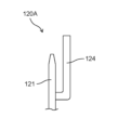
- the extending portion 124 is located between the first connecting pin 121 and the second connecting pin 122 when the connecting terminal 120A is viewed from the front.
- the extending portion 124 extends linearly from the connecting portion 123 in the longitudinal direction of the first connecting pin 121 (which is also the longitudinal direction of the second connecting pin 122).
- the distal end of the extending portion 124 protrudes beyond the distal end of the first connecting pin 121 and the distal end of the second connecting pin 122.
- the first plane including the first connection pin 121 and the second connection pin 122 and the second plane including the extension part 124 are the first connection In the direction intersecting the direction in which the pin and the second connection pin extend, the first connection pin 121 and the second connection pin 122 and the extension portion 124 are located at positions shifted in the front-rear direction.
- the extending portion 124 does not exist in a plane that includes the direction in which the first connecting pins 121 and the second connecting pins 122 are arranged.
- the extending portion 124, the first connecting pin 121, and the second connecting pin 122 are formed at different levels.
- the extending portion 124 protrudes from the connecting portion 123 to the side opposite to the tip end of the first connecting pin 121, then makes a U turn and extends toward the tip end of the first connecting pin 121. .
- the extension part 124 protrudes downward from the lower end of the connection part 123, bends 180 degrees in a U-shape, and extends upward. Extending.
- a cut portion 123a having a width less than the thickness of the metal plate constituting the connection terminal 120A is provided at the connection portion of the connection portion 123 between the first connection pin 121 and the second connection pin 122. That is, the width of the extending portion 124 in the extending direction is narrowed at the connection portion of the connecting portion 123 with the first connecting pin 121 and the second connecting pin 122. Specifically, when the thickness of the metal plate constituting the connection terminal 120A is t and the width of the cut portion 123a is W, W ⁇ t. In this embodiment, the entire connecting portion 123 is a cutting portion 123a.
- connection terminal 120A of this embodiment is a connection terminal 120A to which the winding 12 disposed in the slot 11b of the stator core 11 in the electric motor 1 is connected, and one end of the winding 12 is connected to the connection terminal 120A. It has a first connecting pin 121, a second connecting pin 122 to which the other end of the winding 12 is connected, and a connecting portion 123 connecting the first connecting pin 121 and the second connecting pin 122.
- connection pin from collapsing due to stress or thermal stress.
- the stator assembly 2 of this embodiment includes a stator core 11, a winding 12 disposed in a slot 11b of the stator core 11, a connecting terminal 120 to which the winding 12 is connected, and a circuit board to which the connecting terminal 120 is connected. 20.
- the connection terminal 120 has a first connection pin 121 to which one end of the winding 12 is connected, and a second connection pin 122 to which the other end of the winding 12 is connected.
- a first protrusion 121c whose tip end surface is a broken surface is formed in a part of the end surface of the first connecting pin 121 on the second connecting pin 122 side.
- a second protrusion 122c whose tip end surface is a broken surface is formed on a part of the end surface of the second connection pin 122 on the first connection pin 121 side.
- the electric motor 1 of this embodiment includes a stator assembly 2 and a rotor 30 facing the stator assembly 2.
- FIGS. 13A to 13D are diagrams for explaining a method of manufacturing the stator assembly 2 according to the embodiment.
- FIG. 13A shows the process of preparing intermediate assembly 100A.
- FIG. 13B shows the process of preparing the stator 10 and the circuit board 20.
- FIG. 13C shows the process of connecting the stator 10 and the circuit board 20.
- FIG. 13D shows a step of cutting the connecting portion 123 of the connecting terminal 120A.
- the winding 12 is omitted.
- an intermediate assembly 100A is prepared. Specifically, an intermediate assembly 100A including a core block 110, a connecting terminal 120A, and an insulator 130 is prepared.
- the intermediate assembly 100A is provided with a winding 12. At this time, one end of the winding 12 is connected to the first connection pin 121 of the connection terminal 120A. The other end of the winding 12 is connected to the second connection pin 122 in the connection terminal 120A.
- one end of the winding 12 is tied around the first connection portion 121b of the first connection pin 121 to connect the first connection portion 121b and the winding 12.
- the other end of the winding 12 is tied around the second connection portion 122b of the second connection pin 122 to connect the second connection portion 122b and the winding 12.
- the first connecting pin 121 and the second connecting pin 122 are connected by the connecting part 123. Therefore, it is possible to effectively prevent the first connecting pin 121 and the second connecting pin 122 from falling diagonally due to stress or thermal stress when connecting the first connecting pin 121 and the second connecting pin 122 to the winding 12. can be suppressed to
- the first connection pin 121 and the second connection pin 122 and the winding 12 are connected by fusing. Thereby, stress or thermal stress can be alleviated compared to the case where the first connection pin 121 and the second connection pin 122 and the winding 12 are connected by soldering. Therefore, it is possible to further prevent the first connecting pin 121 and the second connecting pin 122 from falling diagonally.
- the first connection pin 121 and the second connection pin 122 and the winding 12 may be connected by soldering instead of fusing. Even when the first connecting pin 121 and the second connecting pin 122 and the winding 12 are assembled by soldering, the first connecting pin 121 and the second connecting pin 122 are connected at the connecting part 123. This prevents the first connecting pin 121 and the second connecting pin 122 from falling diagonally due to stress or thermal stress when soldering the first connecting pin 121 and the second connecting pin 122 to the winding 12. can do.
- stator 10 and circuit board 20 are prepared. Specifically, a stator 10 having a connection terminal 120A, a stator core 11, and a winding 12 (not shown), and a circuit board 20 are prepared.
- the stator core 11 is composed of a plurality of core blocks 110.
- the connection terminal 120A is provided corresponding to each of the plurality of core blocks 110. Therefore, the stator 10 is prepared using an intermediate assembly 100A composed of one core block 110, one connection terminal 120A, and one winding 12.
- the plurality of intermediate assemblies 100A are arranged in a cylindrical shape. Specifically, the plurality of intermediate assemblies 100A are arranged in an annular shape such that the longitudinal direction of each intermediate assembly 100A is parallel to the cylindrical axis direction of the stator 10. At this time, the plurality of intermediate assemblies 100A are arranged so that the connection terminals 120A of each intermediate assembly 100A are aligned in one direction. That is, the connection terminal 120A in each of the plurality of intermediate assemblies 100A protrudes toward one side of the cylinder axis of the stator 10. Thereby, the stator 10 composed of a plurality of intermediate assemblies 100A arranged in a cylindrical shape can be prepared.
- the stator 10 made up of a plurality of intermediate assemblies 100A and the circuit board 20 are connected. Specifically, the stator 10 is connected to the circuit board 20 by connecting the connection terminal 120A to the circuit board 20. At this time, the connection terminals 120A of all intermediate assemblies 100A in the stator 10 are connected to the circuit board 20 at the same time.
- the first connecting pin 121 and the second connecting pin 122 of the connecting terminal 120A are inserted into the through hole 21 of the circuit board 20 at the same time. More specifically, as shown by the solid arrow in FIG. 13B, the first body portion 121a of the first connecting pin 121 is inserted into one of the two adjacent through holes 21 in each intermediate assembly 100A. The second body portion 122a of the second connecting pin 122 is inserted into the other of the two adjacent through holes 21.
- the first connecting pin 121 and the second connecting pin 122 When inserting the first connecting pin 121 and the second connecting pin 122 into the through hole 21, the first connecting pin 121 and the second connecting pin 122 are press-fitted into the through hole 21. Specifically, the first body portion 121a of the first connecting pin 121 and the second body portion 122a of the second connecting pin 122 are lightly press-fitted into the through hole 21. That is, the first main body part 121a of the first connecting pin 121 and the second main body part 122a of the second connecting pin 122 are pushed into the through hole 21 and tightly fitted into the through hole 21.
- a first slit 121d is formed in the first connection pin 121.
- FIGS. 13B and 13C by press-fitting the first connecting pin 121 into the through hole 21, the stress that the first connecting pin 121 receives from the inner surface of the through hole 21 is absorbed by the first slit 121d. can do.
- a second slit 122d is formed in the second connection pin 122.
- the first connecting pin 121 and the second connecting pin 122 can be fixed to the circuit board 20.
- the connection terminal 120A is fixed to the circuit board 20.
- all the connection terminals 120A are fixed to the circuit board 20 at the same time. Therefore, the intermediate assembly 100A is fixed to the circuit board 20.
- the inner peripheral surface of the through hole 21 of the circuit board 20 is covered with a conductive film electrically connected to the wiring formed on the main surface of the circuit board 20.
- the first connecting pin 121 and the second connecting pin 122 of the connecting terminal 120A are connected to the circuit board 20.
- the first connecting pin 121 and the second connecting pin 122 can be electrically and mechanically connected to the circuit board 20 without soldering.
- the first connecting pin 121 and the second connecting pin 122 may be soldered to the circuit board 20.
- the winding 12 is connected to the first connection pin 121 and the second connection pin 122. Therefore, by press-fitting the first connecting pin 121 and the second connecting pin 122 into the through hole 21, the wiring of the circuit board 20 and the winding 12 are connected via the first connecting pin 121 and the second connecting pin 122. Can be electrically connected.
- the first connecting pin 121 and the second connecting pin 122 are connected by the connecting part 123, and the first connecting pin 121 and the second connecting pin 122 are prevented from falling down. Therefore, when inserting the first connecting pin 121 and the second connecting pin 122 into the circuit board 20, the first connecting pin 121 and the second connecting pin 122 can be inserted into the through hole without interfering with the through hole 21 of the circuit board 20. 21 can be inserted smoothly. Thereby, the quality of the stator assembly 2 can be ensured. Furthermore, it is possible to reduce costs by improving productivity.
- a notch 22 is formed at the end of the circuit board 20.
- the cutout portion 22 is formed to correspond to the extension portion 124 of the connection terminal 120A.
- the extension portion 124 of the connection terminal 120A is inserted into the cutout portion 22, as shown by the dashed arrow in FIG. 13B. That is, when connecting the connection terminal 120A to the circuit board 20, the first connection pin 121 and the second connection pin 122 are inserted into the through hole 21 of the circuit board 20. Further, the extending portion 124 is inserted into the notch portion 22 .
- connection terminal 120A can be easily connected to the circuit board 20.
- the connecting portion 123 of the connecting terminal 120A is cut. Thereby, the first connection pin 121 and the second connection pin 122 are separated.
- the connecting portion 123 is cut by the extending portion 124.
- the tip of the extension portion 124 is pulled toward the user and rotated.
- the extending portion 124 rotates using the connecting portion 123 as a fulcrum. Therefore, according to this principle, the connecting portion 123 can be twisted and cut.
- the connecting portion 123 and the extending portion 124 are removed together from the connecting terminal 120A. That is, the connecting portion 123 and the extending portion 124 are removed from the first connecting pin 121 and the second connecting pin 122.
- the connecting portion 123 can be easily cut. Moreover, the tip of the extending portion 124 protrudes beyond the tip of the first connecting pin 121 and the tip of the second connecting pin 122. Thereby, the tip of the extension portion 124 can be easily pinched. Therefore, the workability when cutting the connecting portion 123 can be improved.
- the first connecting pin 121, the second connecting pin 122, and the extending portion 124 are located at positions shifted from each other in the front-rear direction.
- the extending portion 124 can be pulled forward and rotated easily. This further improves the workability when cutting the connecting portion 123.
- the extending portion 124 protrudes from the connecting portion 123 to the side opposite to the distal end of the first connecting pin 121, and then makes a U-turn to form the distal end of the first connecting pin 121. It extends towards the side.
- a cut portion 123a having a width less than the thickness of the metal plate constituting the connection terminal 120A is provided at the connection portion of the connection portion 123 between the first connection pin 121 and the second connection pin 122. ing.
- the strength of the cut portion 123a can be reduced. Therefore, the connecting portion 123 can be cut more easily at the cutting portion 123a.
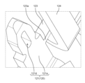
- the connecting portion 123 is cut off from the first connecting pin 121 and the second connecting pin 122, so that a first protrusion is formed on the end surface of the first connecting pin 121 on the second connecting pin 122 side. 121c is formed. Further, a second protrusion 122c is formed on the end surface of the second connection pin 122 on the first connection pin 121 side.
- An example of the first protrusion 121c formed on the first connection pin 121 is shown in the photograph of FIG. 14.
- FIG. 14 is a photograph showing the first protrusion 121c formed on the first connecting pin 121 after cutting the connecting portion 123 of the connecting terminal 120A.
- a stator assembly 2 in which the stator 10 composed of a plurality of intermediate assemblies 100A and the circuit board 20 are combined can be manufactured.
- the method for manufacturing the stator assembly 2 of this embodiment includes the steps of preparing the stator 10 having the connection terminal 120A, the stator core 11, and the winding 12, and connecting the connection terminal 120A to the circuit board 20. connecting the stator 10 to the circuit board 20.
- the connection terminal 120A includes a first connection pin 121 to which one end of the winding 12 is connected, a second connection pin 122 to which the other end of the winding 12 is connected, and the first connection pin 121 and the second connection pin 122. It has a connecting part 123 that connects the.
- the first connection pin 121 and the second connection pin 122 in the connection terminal 120A are electrically and mechanically connected to the circuit board 20.
- the method for manufacturing the stator assembly 2 includes a step of connecting the connecting terminal 120A to the circuit board 20 and then cutting the connecting portion 123 of the connecting terminal 120A.
- stator assembly 2 in which the stator 10, which is composed of a plurality of intermediate assemblies 100A, and the circuit board 20 are combined.
- FIG. 15A is an enlarged front view of the connection terminal 120B according to Modification 1.
- FIG. 15B is a cross-sectional view of the connection terminal 120B according to Modification 1 taken along line BB in FIG. 15A.
- a groove 125 extending across the entire width of the connecting portion 123 may be formed on the surface of the metal plate in the connecting portion 123.
- the groove 125 is, for example, a V-shaped groove with a V-shaped cross section.
- the connecting portion 123 can be cut more easily.
- the groove 125 may be formed in the cut portion 123a of the connecting portion 123. Thereby, the connecting portion 123 can be cut more easily.
- the grooves 125 may be formed facing each other on both surfaces of the metal plate in the connecting portion 123. Thereby, the connecting portion 123 can be cut much more easily.
- connection terminal 120A in the above embodiment, the first connection pin 121, the second connection pin 122, and the extension portion 124 are shifted from each other in the front-rear direction.
- FIG. 16 is an enlarged front view of a connection terminal 120C according to modification 2.
- the two connection pins 122 and the extension portion 124C may be configured to form the same plane. That is, both surfaces of each of the first connection pin 121, the second connection pin 122, and the extension portion 124C may be flush with each other.
- FIG. 17 is an enlarged front view of a connection terminal 120D according to modification 3.
- the first connection pin 121 and the second connection pin 122 may be connected only by the connection part 123.
- connection terminal 120A is applied to the circuit board 20 in the stator assembly 2.
- the connection terminal 120A can be widely applied to circuit boards used in the electric motor 1.
- the connection terminal 120A may be applied to a circuit board of an encoder included in a motor.
- the rotor 30 is an IPM rotor.
- the rotor 30 may be a surface permanent magnetic rotor (SPM (Surface Permanent Magnetic) rotor) in which a plurality of permanent magnets are provided on the outer surface of a rotor core.
- SPM Surface Permanent Magnetic
- the rotor 30 is a laminate in which a plurality of steel plates are laminated. However, it is not limited to this.
- the rotor 30 may be made of bulk material.
- the electric motor 1 has 6 poles and 12 slots. However, it is not limited to this. In other words, the number of slots in the stator 10 is not limited to twelve.
- the number of magnetic poles of the rotor 30 is not limited to six (that is, the number of permanent magnets 33 is six). Any number of slots in the stator 10 and any number of magnetic poles in the rotor 30 can be used.
- the technology of the present disclosure can be widely used in electric motors, electrical equipment equipped with electric motors, and the like.
- Second bracket 100 100A Intermediate assembly 110 Core block 111 Teeth portion 112 Yoke portion 120, 120A, 120B, 120C, 120D Connection terminal 121 First connection pin 121a First main body portion 121b First connection portion 121c 1 protrusion 121d 1st slit 122 2nd connection pin 122a 2nd main body part 122b 2nd connection part 122c 2nd protrusion 122d 2nd slit 123 Connection part 123a Cutting part 124, 124C Extension part 125 Groove 130 Insulator 131 1st insulator 132 2nd insulator
Landscapes
- Engineering & Computer Science (AREA)
- Power Engineering (AREA)
- Manufacturing & Machinery (AREA)
- Insulation, Fastening Of Motor, Generator Windings (AREA)
Abstract
Description
まず、実施の形態に係る電動機1の構成について、図1~図6を用いて説明する。図1は、回転軸31を通る平面で切断したときの実施の形態に係る電動機1の断面図である。図2は、回転軸31と直交する平面で切断したときの実施の形態に係る電動機1の断面図である。図2は、図1のII-II線における断面を示している。図3は、実施の形態に係る電動機1を斜め上方から見たときの分解斜視図である。図4は、実施の形態に係る電動機1を斜め下方から見たときの分解斜視図である。図3及び図4において、巻線12は省略している。図5は、実施の形態に係るステータ組立体2の斜視図である。図6は、実施の形態に係るステータ組立体2の断面図である。
以上、本開示について、実施の形態に基づいて説明した。しかし、本開示は、上記実施の形態に限定されるものではない。
2 ステータ組立体
10 ステータ
11 ステータコア
11a ティース
11b スロット
12 巻線
20 回路基板
21 貫通孔
22 切り欠き部
30 ロータ
31 回転軸
32 ロータコア
32a 磁石挿入穴
33 永久磁石
41 第1軸受け
42 第2軸受け
51 第1ブラケット
52 第2ブラケット
100、100A 中間組立体
110 コアブロック
111 ティース部
112 ヨーク部
120、120A、120B、120C、120D 接続端子
121 第1接続ピン
121a 第1本体部
121b 第1結線部
121c 第1突起
121d 第1スリット
122 第2接続ピン
122a 第2本体部
122b 第2結線部
122c 第2突起
122d 第2スリット
123 連結部
123a 切断部
124、124C 延在部
125 溝
130 インシュレータ
131 第1インシュレータ
132 第2インシュレータ
Claims (16)
- 電動機におけるステータコアのスロットに配置される巻線が結線される接続端子であって、
前記巻線の一端が結線される第1接続ピンと、
前記巻線の他端が結線される第2接続ピンと、
前記第1接続ピンと前記第2接続ピンとを連結する連結部とを有する、
接続端子。 - 前記接続端子は、金属板によって構成されており、
前記連結部における前記第1接続ピン及び前記第2接続ピンとの接続部分には、前記金属板の板厚未満の幅を有する切断部が設けられている、
請求項1に記載の接続端子。 - 前記第1接続ピン及び前記第2接続ピンが延伸する方向を幅方向とし、前記連結部における前記金属板の表面に、前記連結部の前記幅方向全体に延在する溝が形成されている、
請求項2に記載の接続端子。 - さらに、前記接続端子を正面から見たときに、前記第1接続ピンと前記第2接続ピンとの間に位置し、前記連結部から前記第1接続ピンの長手方向に延在する延在部を有する、
請求項1~3のいずれか1項に記載の接続端子。 - 前記接続端子を側方から見たときに、前記第1接続ピン及び前記第2接続ピンと前記延在部とは、前記第1接続ピン及び前記第2接続ピンを含む第1平面と前記延在部を含む第2平面とは前記第1接続ピン及び前記第2接続ピンが延伸する方向に交差する方向において前後方向にずれた位置に存在している、
請求項4に記載の接続端子。 - 前記延在部は、前記連結部から、前記第1接続ピンの先端部側とは反対側に突出してからUターンして、前記第1接続ピンの先端部側に向かって延在している、
請求項5に記載の接続端子。 - 前記第1接続ピンは、一方向に延在する第1本体部と、前記巻線の一端が結線される第1結線部とを有し、
前記第2接続ピンは、前記一方向に延在する第2本体部と、前記巻線の他端が結線される第2結線部とを有し、
前記第1結線部は、前記第1本体部の外側の側部から突出して、前記第1本体部に対向するように内側に向かって折れ曲がっており、
前記第2結線部は、前記第2本体部の外側の側部から突出して、前記第2本体部に対向するように内側に向かって折れ曲がっている、
請求項1~3のいずれか1項に記載の接続端子。 - 前記ステータコアは、複数のコアブロックに分割されており、
前記接続端子は、前記複数のコアブロックの各々に対応して設けられる、
請求項1~3のいずれか1項に記載の接続端子。 - ステータコアと、
前記ステータコアのスロットに配置された巻線と、
前記巻線が結線される接続端子と、
前記接続端子が接続された回路基板と、を備え、
前記接続端子は、前記巻線の一端が結線される第1接続ピンと、前記巻線の他端が結線される第2接続ピンと、を有し、
前記第1接続ピンにおける前記第2接続ピン側の端面の一部に、先端面が破断面である突起が形成されており、
前記第2接続ピンにおける前記第1接続ピン側の端面の一部に、先端面が破断面である突起が形成されている、
ステータ組立体。 - 前記ステータコアは、複数のコアブロックによって構成されており、
前記接続端子は、前記複数のコアブロックの各々に対応して設けられている、
請求項9に記載のステータ組立体。 - 前記接続端子は、前記複数のコアブロックに固定されたインシュレータに保持されている、
請求項10に記載のステータ組立体。 - 請求項9~11のいずれか1項に記載のステータ組立体と、
前記ステータ組立体と向かい合うロータと、を備える、
電動機。 - ステータ組立体の製造方法であって、
接続端子、ステータコア及び巻線を有するステータを準備する工程と、
前記接続端子を回路基板に接続することで前記ステータを前記回路基板に接続する工程と、を含み、
前記接続端子は、前記巻線の一端が結線される第1接続ピンと、前記巻線の他端が結線される第2接続ピンと、前記第1接続ピンと前記第2接続ピンとを連結する連結部とを有し、
前記ステータを前記回路基板に接続する工程では、前記接続端子における第1接続ピン及び前記第2接続ピンと前記回路基板とを電気的及び機械的に接続し、
前記ステータ組立体の製造方法は、前記接続端子を前記回路基板に接続した後に、前記接続端子の前記連結部を切断する工程を含む、
ステータ組立体の製造方法。 - 前記接続端子は、さらに、前記第1接続ピンと前記第2接続ピンとの間に位置し、前記連結部から前記第1接続ピン及び前記第2接続ピンの長手方向に延在する延在部を有し、
前記回路基板の端部に、切り欠き部が形成されており、
前記ステータを前記回路基板に接続する工程では、前記第1接続ピン及び前記第2接続ピンを前記回路基板に設けられた貫通孔に挿入するとともに、前記延在部を前記切り欠き部に挿入し、
前記連結部を切断する工程では、前記連結部を支点として前記延在部を回転させることで前記連結部を切断することで、前記連結部及び前記延在部を一体として、前記第1接続ピン及び第2接続ピンから取り外す、
請求項13に記載のステータ組立体の製造方法。 - 前記巻線の一端を前記第1接続ピンに結線するとともに、前記巻線の他端を前記第2接続ピンに結線した後に、前記接続端子の前記連結部を切断する、
請求項13又は14に記載のステータ組立体の製造方法。 - 前記ステータコアは、複数のコアブロックによって構成されており、
前記接続端子は、前記複数のコアブロックの各々に対応して設けられており、
一つの前記コアブロックと一つの前記接続端子と一つの前記巻線とで、中間組立体が構成されており、
前記ステータは、複数の前記中間組立体を筒状に配置することで構成されており、
前記ステータにおいて、複数の前記中間組立体の各々における前記接続端子は、前記ステータの筒軸方向の一方に向かって突出している、
請求項13又は14に記載のステータ組立体の製造方法。
Priority Applications (2)
| Application Number | Priority Date | Filing Date | Title |
|---|---|---|---|
| JP2024522939A JPWO2023228551A1 (ja) | 2022-05-27 | 2023-03-28 | |
| CN202380041005.6A CN119213671A (zh) | 2022-05-27 | 2023-03-28 | 连接端子、定子组装体、电动机和定子组装体的制造方法 |
Applications Claiming Priority (2)
| Application Number | Priority Date | Filing Date | Title |
|---|---|---|---|
| JP2022087091 | 2022-05-27 | ||
| JP2022-087091 | 2022-05-27 |
Publications (1)
| Publication Number | Publication Date |
|---|---|
| WO2023228551A1 true WO2023228551A1 (ja) | 2023-11-30 |
Family
ID=88919062
Family Applications (1)
| Application Number | Title | Priority Date | Filing Date |
|---|---|---|---|
| PCT/JP2023/012454 Ceased WO2023228551A1 (ja) | 2022-05-27 | 2023-03-28 | 接続端子、ステータ組立体、電動機及びステータ組立体の製造方法 |
Country Status (3)
| Country | Link |
|---|---|
| JP (1) | JPWO2023228551A1 (ja) |
| CN (1) | CN119213671A (ja) |
| WO (1) | WO2023228551A1 (ja) |
Citations (8)
| Publication number | Priority date | Publication date | Assignee | Title |
|---|---|---|---|---|
| JPH08280150A (ja) * | 1995-04-09 | 1996-10-22 | Mabuchi Motor Co Ltd | 小型モータ |
| JP2003111348A (ja) * | 2001-09-26 | 2003-04-11 | Asmo Co Ltd | コネクタ装置及びその製造方法 |
| JP2009118615A (ja) * | 2007-11-05 | 2009-05-28 | Mitsuba Corp | ブラシレスモータ |
| US20100109458A1 (en) * | 2008-11-04 | 2010-05-06 | Knf Neuberger Gmbh | Brushless direct current motor |
| JP2015097450A (ja) * | 2013-11-15 | 2015-05-21 | アイシン精機株式会社 | 回転電機 |
| JP2017073897A (ja) * | 2015-10-07 | 2017-04-13 | トヨタ自動車株式会社 | 回転電機の端子台接続構造 |
| JP2020088981A (ja) * | 2018-11-20 | 2020-06-04 | 日本電産株式会社 | ステータユニット、モータ、および、送風装置 |
| JP2020096459A (ja) * | 2018-12-13 | 2020-06-18 | 株式会社デンソー | モータ及びモータの製造方法 |
-
2023
- 2023-03-28 CN CN202380041005.6A patent/CN119213671A/zh active Pending
- 2023-03-28 WO PCT/JP2023/012454 patent/WO2023228551A1/ja not_active Ceased
- 2023-03-28 JP JP2024522939A patent/JPWO2023228551A1/ja active Pending
Patent Citations (8)
| Publication number | Priority date | Publication date | Assignee | Title |
|---|---|---|---|---|
| JPH08280150A (ja) * | 1995-04-09 | 1996-10-22 | Mabuchi Motor Co Ltd | 小型モータ |
| JP2003111348A (ja) * | 2001-09-26 | 2003-04-11 | Asmo Co Ltd | コネクタ装置及びその製造方法 |
| JP2009118615A (ja) * | 2007-11-05 | 2009-05-28 | Mitsuba Corp | ブラシレスモータ |
| US20100109458A1 (en) * | 2008-11-04 | 2010-05-06 | Knf Neuberger Gmbh | Brushless direct current motor |
| JP2015097450A (ja) * | 2013-11-15 | 2015-05-21 | アイシン精機株式会社 | 回転電機 |
| JP2017073897A (ja) * | 2015-10-07 | 2017-04-13 | トヨタ自動車株式会社 | 回転電機の端子台接続構造 |
| JP2020088981A (ja) * | 2018-11-20 | 2020-06-04 | 日本電産株式会社 | ステータユニット、モータ、および、送風装置 |
| JP2020096459A (ja) * | 2018-12-13 | 2020-06-18 | 株式会社デンソー | モータ及びモータの製造方法 |
Also Published As
| Publication number | Publication date |
|---|---|
| JPWO2023228551A1 (ja) | 2023-11-30 |
| CN119213671A (zh) | 2024-12-27 |
Similar Documents
| Publication | Publication Date | Title |
|---|---|---|
| JP5519808B2 (ja) | ステータおよびこのステータを備える回転電機 | |
| CN109075681B (zh) | 电动机及空气调节机 | |
| US6194806B1 (en) | Compact cylindrical radial gap type motor | |
| JP5734794B2 (ja) | ステータおよびこのステータを備える回転電機 | |
| CN113939979B (zh) | 线圈和具有该线圈的定子、转子、电动机以及线圈的制造方法 | |
| US7928619B2 (en) | Gap winding motor | |
| JPWO2020255614A5 (ja) | ||
| KR20180054087A (ko) | 스테이터 일체형 차량용 팬모터 | |
| JP5277743B2 (ja) | 回転電機 | |
| WO2023228551A1 (ja) | 接続端子、ステータ組立体、電動機及びステータ組立体の製造方法 | |
| WO2023228581A1 (ja) | 接続端子、ステータ組立体及び電動機 | |
| WO2024034364A1 (ja) | コイル、ステータ及び回転電機 | |
| JPH10271795A (ja) | ステッピングモータ | |
| CN108886304A (zh) | 电动马达用定子的制造方法、电动马达的制造方法、电动马达用定子以及电动马达 | |
| JP5738084B2 (ja) | 整流子、整流子を備えた回転子及び、整流子を備えた回転子の製造方法 | |
| JP2018207616A (ja) | モータ | |
| JPWO2021256178A5 (ja) | ||
| WO2021256178A1 (ja) | 成形コイル、ステータ及び回転電機 | |
| JPS63299745A (ja) | 電動機 | |
| EP4535615A1 (en) | Electric motor, core block, and stator core | |
| CN115552768A (zh) | 转子及电动机 | |
| JP2022117165A (ja) | ステータ、モータ、及び、ステータの製造方法 | |
| JP7800212B2 (ja) | 電機子及び回転電機 | |
| JP2020127362A (ja) | モータ | |
| EP4625773A1 (en) | Stator and motor |
Legal Events
| Date | Code | Title | Description |
|---|---|---|---|
| 121 | Ep: the epo has been informed by wipo that ep was designated in this application |
Ref document number: 23811430 Country of ref document: EP Kind code of ref document: A1 |
|
| WWE | Wipo information: entry into national phase |
Ref document number: 2024522939 Country of ref document: JP |
|
| WWE | Wipo information: entry into national phase |
Ref document number: 202380041005.6 Country of ref document: CN |
|
| WWP | Wipo information: published in national office |
Ref document number: 202380041005.6 Country of ref document: CN |
|
| NENP | Non-entry into the national phase |
Ref country code: DE |
|
| 122 | Ep: pct application non-entry in european phase |
Ref document number: 23811430 Country of ref document: EP Kind code of ref document: A1 |