WO2023228261A1 - 配管点検装置 - Google Patents
配管点検装置 Download PDFInfo
- Publication number
- WO2023228261A1 WO2023228261A1 PCT/JP2022/021165 JP2022021165W WO2023228261A1 WO 2023228261 A1 WO2023228261 A1 WO 2023228261A1 JP 2022021165 W JP2022021165 W JP 2022021165W WO 2023228261 A1 WO2023228261 A1 WO 2023228261A1
- Authority
- WO
- WIPO (PCT)
- Prior art keywords
- link members
- inspection device
- ultrasonic probe
- gripping member
- pipe
- Prior art date
- Legal status (The legal status is an assumption and is not a legal conclusion. Google has not performed a legal analysis and makes no representation as to the accuracy of the status listed.)
- Ceased
Links
Images




Classifications
-
- G—PHYSICS
- G01—MEASURING; TESTING
- G01N—INVESTIGATING OR ANALYSING MATERIALS BY DETERMINING THEIR CHEMICAL OR PHYSICAL PROPERTIES
- G01N29/00—Investigating or analysing materials by the use of ultrasonic, sonic or infrasonic waves; Visualisation of the interior of objects by transmitting ultrasonic or sonic waves through the object
- G01N29/04—Analysing solids
-
- G—PHYSICS
- G01—MEASURING; TESTING
- G01B—MEASURING LENGTH, THICKNESS OR SIMILAR LINEAR DIMENSIONS; MEASURING ANGLES; MEASURING AREAS; MEASURING IRREGULARITIES OF SURFACES OR CONTOURS
- G01B17/00—Measuring arrangements characterised by the use of infrasonic, sonic or ultrasonic vibrations
- G01B17/02—Measuring arrangements characterised by the use of infrasonic, sonic or ultrasonic vibrations for measuring thickness
-
- G—PHYSICS
- G01—MEASURING; TESTING
- G01B—MEASURING LENGTH, THICKNESS OR SIMILAR LINEAR DIMENSIONS; MEASURING ANGLES; MEASURING AREAS; MEASURING IRREGULARITIES OF SURFACES OR CONTOURS
- G01B5/00—Measuring arrangements characterised by the use of mechanical techniques
- G01B5/0002—Arrangements for supporting, fixing or guiding the measuring instrument or the object to be measured
- G01B5/0004—Supports
-
- G—PHYSICS
- G01—MEASURING; TESTING
- G01N—INVESTIGATING OR ANALYSING MATERIALS BY DETERMINING THEIR CHEMICAL OR PHYSICAL PROPERTIES
- G01N29/00—Investigating or analysing materials by the use of ultrasonic, sonic or infrasonic waves; Visualisation of the interior of objects by transmitting ultrasonic or sonic waves through the object
- G01N29/22—Details, e.g. general constructional or apparatus details
- G01N29/225—Supports, positioning or alignment in moving situation
-
- G—PHYSICS
- G01—MEASURING; TESTING
- G01N—INVESTIGATING OR ANALYSING MATERIALS BY DETERMINING THEIR CHEMICAL OR PHYSICAL PROPERTIES
- G01N2291/00—Indexing codes associated with group G01N29/00
- G01N2291/26—Scanned objects
- G01N2291/263—Surfaces
- G01N2291/2634—Surfaces cylindrical from outside
Definitions
- the present invention relates to a pipe inspection device that can be attached to the tip of a robot arm and performs ultrasonic thickness measurements on pipes of various sizes.
- piping installed in factories etc. gradually decreases in thickness and strength due to corrosion and the like. Piping owners must regularly check the thickness of their pipes, as loss of strength can lead to accidents.
- One of the inspection methods is to measure the thickness of the pipe by bringing an ultrasonic probe into contact with the surface of the pipe to irradiate ultrasonic waves and detecting reflected waves from the inner surface of the pipe. Normally, this work is performed by humans, but if a robot arm performs this work instead of a human, safe and efficient inspection work becomes possible.
- the ultrasonic probe In thickness measurement using an ultrasonic probe, the ultrasonic probe must be pressed so that the direction of incidence of the ultrasonic waves is approximately perpendicular to the surface of the object to be inspected (this state is (we will say that the sonic probe is perpendicular to the surface of the object to be inspected).
- this state is (we will say that the sonic probe is perpendicular to the surface of the object to be inspected).
- some kind of device is required to appropriately guide the position and orientation of the ultrasound probe.
- Patent Document 1 discloses an inspection device in which an ultrasonic probe is held by a frame having two rotation axes and is pressed perpendicularly to an object to be inspected.
- Patent Document 2 discloses an ultrasonic inspection device in which a similar device is attached to the tip of a robot arm.
- Patent Document 3 discloses a piping inspection device that finely adjusts the attitude of an ultrasonic probe using a parallel link.
- Patent Document 4 discloses a multi-jointed hand that can grasp various objects. It is also possible to configure a piping inspection device that mounts an ultrasonic probe inside such a hand and guides the ultrasonic probe.
- Patent Document 1 and Patent Document 2 above adjusts the posture of the ultrasound probe by pressing the ultrasound probe against an object to be inspected that has a gently curved surface.
- the angle of the surface changes by about 45 degrees.
- the ultrasonic probe slips on the surface of the pipe, making it difficult to maintain the position and posture of the ultrasonic probe appropriately.
- Patent Document 3 since the device disclosed in Patent Document 3 is complicated and large, it is difficult to use it by attaching it to the tip of a robot arm.
- the present invention has been made in view of the above, and provides a pipe inspection device that can press an ultrasonic probe substantially perpendicularly to the surface of pipes of various sizes.
- the purpose is to
- One aspect of the present invention that solves the above-mentioned problems and achieves the object includes a multi-joint gripping member, a base, one or more ultrasound probe holding members, and a drive device for driving the multi-joint gripping member.
- the multi-joint gripping member is constructed of four or more link members of a certain length connected in series via a rotating shaft, mechanical restraint means that always keeps the angles formed by adjacent link members substantially equal;
- the base is fixed to one of the link members constituting the multi-joint gripping member, the ultrasonic probe holding member is fixed to the center of one of the link members, and the drive device is fixed to the multi-joint gripping member.
- a piping inspection device characterized in that it is fixed to one of the link members constituting the members or to the base.
- the ultrasonic probe holding member is connected to the multi-joint gripping mechanism by a two-axis gimbal mechanism.
- the mechanical restraint means for always keeping the angles formed by adjacent link members of the multi-joint gripping member substantially equal is constituted by a four-section link mechanism.
- the ultrasonic probe holding member has a tube for supplying a couplant for ultrasonic measurement and a bellows for holding the couplant.
- the multi-joint gripping member includes an angle sensor that measures an angle formed by adjacent link members.
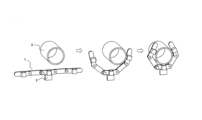
- FIG. 1 is a diagram of a piping inspection device according to an embodiment. It is a figure showing the guidance operation by a multi-joint grasping member.
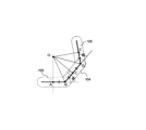
- FIG. 3 is a diagram showing a geometric model of a multi-joint gripping member.
- FIG. 4 is a diagram illustrating problems in the mechanism based on Patent Document 4.
- FIG. 3 is a diagram showing an ultrasound probe holding member having a two-axis gimbal mechanism.
- FIG. 6 is a diagram showing a case where a four-bar linkage mechanism is used to equalize the angles formed by link members.
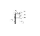
- FIG. 3 shows an ultrasound probe holding member having a couplant supply tube and a bellows. It is a figure showing the piping inspection device which has a sensor which measures the angle which a link member makes.
- FIG. 1 shows an example of a mode for carrying out the present invention.
- the pipe inspection device includes a multi-joint gripping member 1, a base 2, three ultrasonic probe holding members 3, and a drive device 4 for driving the multi-joint gripping member 1.
- the multi-joint gripping member 1 includes a plurality of link members 101 to 105 of a constant length connected in series via a rotating shaft, and mechanical restraint means (not shown) that always maintains substantially the same angles between adjacent link members. , is made up of.
- the base 2 is fixed to the link member 103.
- the ultrasonic probe holding member 3 is fixed at the center of the link members 101, 103, and 105.
- the piping inspection device holds the piping 5 to be inspected.
- the base 2 is attached to the tip of a robot arm (not shown) as the base of the piping inspection device.
- the drive device 4 is fixed to the link member 103.
- the drive device 4 may be an electric motor, a solenoid, a pneumatic cylinder, or the like, and generates a torque that rotates the link member 102.
- FIG. 2 shows the movement of the multi-joint gripping member 1.
- the torque generated by the drive device 4 drives the multi-joint gripping member 1 in the direction of gripping the pipe 5. Then, one end of the multi-joint gripping member 1 comes into contact with the pipe 5. At this time, when the link member 103 is pressed against the pipe 5 by the robot arm, the center of the link member 103 is guided toward the pipe 5 due to the reaction force that the multi-joint gripping member 1 receives from the pipe. When the center of the link member 103 contacts the pipe 5, the multi-joint gripping member 1 grips the pipe 5.
- the ultrasound probe holding member 3 fixed at the center of the link member 103 holds the ultrasound probe perpendicularly to the pipe 5. Press against it.
- the ultrasonic probe holding member 3 attached to the link members 101 and 105 also presses the ultrasonic probe against the pipe 5 perpendicularly.
- FIG. 3 shows a geometric model of the articulated gripping member 1.
- Points A, C, and E are the centers of link members 103, 104, and 105, respectively.
- Points B and D are rotation axes that connect link members 103 and 104, and 104 and 105, respectively.
- Point O is the intersection of the perpendicular line of AB passing through point A and the perpendicular bisector of line segment BD.
- the gripping device 7 is composed of finger members 701 to 705, and the ultrasound probe holding member 3 is fixed to the center of the finger members 701, 703, and 705.
- the gripping device 7 grips the pipe 5
- the finger members 701 and 702, and the finger members 704 and 705 rotate around rotational supports 712 and 714, respectively, while being integrated.
- the finger members 701 and 705 rotate around the rotational supports 712 and 714, respectively, and grip the pipe 5. do.
- the shape of the multi-joint gripping member 1 does not completely match the geometric model shown in FIG. 3 due to errors in component dimensions and play in the rotation axis. Therefore, although the ultrasonic probe is approximately perpendicular to the surface of the pipe 5, it is not completely perpendicular.
- the ultrasonic probe holding member 3 is equipped with a two-axis gimbal consisting of an ultrasonic probe holder 302, frames 303, and 304, the ultrasonic probe 301 can assume a vertical posture with respect to the pipe 5 due to the reaction force that its contact surface receives. For this reason, it is preferable that the ultrasonic probe holding member 3 includes a two-axis gimbal mechanism.
- the mechanical restraint means that always keeps the angles formed by adjacent link members substantially equal may be configured by, for example, a gear, a timing belt, a link mechanism, or the like.
- FIG. 6 shows a multi-joint gripping member 1 in which a four-bar linkage mechanism is configured by a link bar 110.
- four-bar link mechanisms have fewer parts and have the advantage of being less likely to break.
- the four-bar linkage mechanism has a problem in that it does not operate well in a posture close to the singularity.
- FIG. 7 shows an ultrasound probe holding member 3 comprising a tube 312 for supplying a couplant 311 and a bellows 310 for holding the couplant 311.
- a couplant 311 is stored inside the bellows 310 via a tube 312 from a couplant supply device (not shown).
- the bellows 310 is compressed, and the couplant 311 is pushed out and covers the surface of the ultrasonic probe 301.
- the ultrasonic probe holding section 3 may include the tube 312 for supplying the couplant 311 and the bellows 310 for holding the couplant.
- the multi-joint gripping member 1 may include an angle sensor 800 for measuring the angle formed by adjacent link members, as shown in FIG. The angle measured by the angle sensor 800 can be used to control the movement of the multi-joint gripping member.
- the number of link members constituting the multi-joint gripping member 1 may be six.
- the number of ultrasonic probes 3 may be two.
Landscapes
- Physics & Mathematics (AREA)
- General Physics & Mathematics (AREA)
- Health & Medical Sciences (AREA)
- Life Sciences & Earth Sciences (AREA)
- Chemical & Material Sciences (AREA)
- Analytical Chemistry (AREA)
- Biochemistry (AREA)
- General Health & Medical Sciences (AREA)
- Immunology (AREA)
- Pathology (AREA)
- Acoustics & Sound (AREA)
- Investigating Or Analyzing Materials By The Use Of Ultrasonic Waves (AREA)
Priority Applications (7)
| Application Number | Priority Date | Filing Date | Title |
|---|---|---|---|
| JP2024522752A JP7788189B2 (ja) | 2022-05-23 | 2022-05-23 | 配管点検装置 |
| EP22943666.2A EP4530625A4 (en) | 2022-05-23 | 2022-05-23 | PIPE INSPECTION DEVICE |
| US18/861,712 US20250297989A1 (en) | 2022-05-23 | 2022-05-23 | Pipe inspection device |
| PCT/JP2022/021165 WO2023228261A1 (ja) | 2022-05-23 | 2022-05-23 | 配管点検装置 |
| CA3256337A CA3256337A1 (en) | 2022-05-23 | 2022-05-23 | Pipe inspection device |
| CN202280095872.3A CN119156535A (zh) | 2022-05-23 | 2022-05-23 | 配管检查装置 |
| AU2022460087A AU2022460087A1 (en) | 2022-05-23 | 2022-05-23 | Pipe inspection device |
Applications Claiming Priority (1)
| Application Number | Priority Date | Filing Date | Title |
|---|---|---|---|
| PCT/JP2022/021165 WO2023228261A1 (ja) | 2022-05-23 | 2022-05-23 | 配管点検装置 |
Publications (1)
| Publication Number | Publication Date |
|---|---|
| WO2023228261A1 true WO2023228261A1 (ja) | 2023-11-30 |
Family
ID=88918633
Family Applications (1)
| Application Number | Title | Priority Date | Filing Date |
|---|---|---|---|
| PCT/JP2022/021165 Ceased WO2023228261A1 (ja) | 2022-05-23 | 2022-05-23 | 配管点検装置 |
Country Status (7)
| Country | Link |
|---|---|
| US (1) | US20250297989A1 (https=) |
| EP (1) | EP4530625A4 (https=) |
| JP (1) | JP7788189B2 (https=) |
| CN (1) | CN119156535A (https=) |
| AU (1) | AU2022460087A1 (https=) |
| CA (1) | CA3256337A1 (https=) |
| WO (1) | WO2023228261A1 (https=) |
Citations (9)
| Publication number | Priority date | Publication date | Assignee | Title |
|---|---|---|---|---|
| JPH0348761U (https=) * | 1989-09-21 | 1991-05-10 | ||
| US5576492A (en) | 1995-01-26 | 1996-11-19 | United Technologies Corporation | Mechanical contour follower |
| JP2000088824A (ja) | 1998-09-08 | 2000-03-31 | Shinryo Corp | 超音波探触子による配管診断方法と装置 |
| JP2001147287A (ja) * | 1999-11-19 | 2001-05-29 | Hitachi Ltd | 遠隔点検検査システムと遠隔保修システム |
| JP2001194352A (ja) * | 2000-01-05 | 2001-07-19 | Kansai X Sen Kk | 管状部材の超音波検査装置 |
| JP2006313081A (ja) * | 2005-05-06 | 2006-11-16 | Chugoku Regional Development Bureau Ministry Of Land Infrastructure & Transport | 探傷装置 |
| EP1744157A2 (en) | 2005-07-11 | 2007-01-17 | The Boeing Company | Ultrasonic inspection apparatus, system and method |
| JP2013154409A (ja) | 2012-01-26 | 2013-08-15 | Thk Co Ltd | 関節機構、指及びハンド |
| CN108226299A (zh) * | 2016-12-22 | 2018-06-29 | 湘潭宏远电子科技有限公司 | 一种用于圆管角焊缝的超声波检测装置 |
Family Cites Families (1)
| Publication number | Priority date | Publication date | Assignee | Title |
|---|---|---|---|---|
| KR101386252B1 (ko) * | 2012-09-14 | 2014-04-21 | 한국동서발전(주) | 배관 검사 장치 및 배관 검사 시스템 |
-
2022
- 2022-05-23 EP EP22943666.2A patent/EP4530625A4/en active Pending
- 2022-05-23 US US18/861,712 patent/US20250297989A1/en active Pending
- 2022-05-23 WO PCT/JP2022/021165 patent/WO2023228261A1/ja not_active Ceased
- 2022-05-23 AU AU2022460087A patent/AU2022460087A1/en active Pending
- 2022-05-23 JP JP2024522752A patent/JP7788189B2/ja active Active
- 2022-05-23 CA CA3256337A patent/CA3256337A1/en active Pending
- 2022-05-23 CN CN202280095872.3A patent/CN119156535A/zh active Pending
Patent Citations (9)
| Publication number | Priority date | Publication date | Assignee | Title |
|---|---|---|---|---|
| JPH0348761U (https=) * | 1989-09-21 | 1991-05-10 | ||
| US5576492A (en) | 1995-01-26 | 1996-11-19 | United Technologies Corporation | Mechanical contour follower |
| JP2000088824A (ja) | 1998-09-08 | 2000-03-31 | Shinryo Corp | 超音波探触子による配管診断方法と装置 |
| JP2001147287A (ja) * | 1999-11-19 | 2001-05-29 | Hitachi Ltd | 遠隔点検検査システムと遠隔保修システム |
| JP2001194352A (ja) * | 2000-01-05 | 2001-07-19 | Kansai X Sen Kk | 管状部材の超音波検査装置 |
| JP2006313081A (ja) * | 2005-05-06 | 2006-11-16 | Chugoku Regional Development Bureau Ministry Of Land Infrastructure & Transport | 探傷装置 |
| EP1744157A2 (en) | 2005-07-11 | 2007-01-17 | The Boeing Company | Ultrasonic inspection apparatus, system and method |
| JP2013154409A (ja) | 2012-01-26 | 2013-08-15 | Thk Co Ltd | 関節機構、指及びハンド |
| CN108226299A (zh) * | 2016-12-22 | 2018-06-29 | 湘潭宏远电子科技有限公司 | 一种用于圆管角焊缝的超声波检测装置 |
Non-Patent Citations (1)
| Title |
|---|
| See also references of EP4530625A4 |
Also Published As
| Publication number | Publication date |
|---|---|
| EP4530625A1 (en) | 2025-04-02 |
| EP4530625A4 (en) | 2026-04-22 |
| US20250297989A1 (en) | 2025-09-25 |
| JP7788189B2 (ja) | 2025-12-18 |
| CN119156535A (zh) | 2024-12-17 |
| CA3256337A1 (en) | 2025-06-18 |
| AU2022460087A1 (en) | 2024-12-05 |
| JPWO2023228261A1 (https=) | 2023-11-30 |
Similar Documents
| Publication | Publication Date | Title |
|---|---|---|
| US10209152B2 (en) | Force sensor unit and robot arm including a wire cable routed from inside a casing to outside of the casing | |
| JP5544946B2 (ja) | ロボットハンド | |
| JP4469925B2 (ja) | ロボットハンド及びロボットアーム | |
| CN107000224B (zh) | 机械手系统及末端执行器的变形检测方法 | |
| TWI360136B (en) | Apparatus and method for processing inside of pipe | |
| JPS59501679A (ja) | 位置検出装置 | |
| KR20180019720A (ko) | 힘 측정 장치를 갖는 로봇 | |
| CN110753605B (zh) | 在抓具的传动构件轴承上具有传感器的抓具 | |
| JP2019162700A (ja) | ケーブルクランプおよびロボット | |
| CN112351869A (zh) | 具有高精度夹持力传感器的夹持器 | |
| JP5681385B2 (ja) | 自動位置合わせプローブアセンブリを有する非破壊検査システム | |
| CN109153130B (zh) | 具有驱动装置的机器人夹持器 | |
| CN119658667A (zh) | 驱动装置、控制方法、机器人、记录介质和产品制造方法 | |
| WO2023228261A1 (ja) | 配管点検装置 | |
| JPH0257974A (ja) | 管内走行装置 | |
| JP7410189B2 (ja) | ロボットのキャリブレーション装置 | |
| US20180200892A1 (en) | Robot | |
| JP2020179483A (ja) | ロボット | |
| JP7256289B2 (ja) | 超音波プローブの位置ずれ量測定装置 | |
| WO2022185424A1 (ja) | エンドエフェクタ、ロボットアーム及び検査用ロボット | |
| KR102212905B1 (ko) | 일정 검사 압력을 유지하는 풍력 블레이드 검사 플랫폼 장치 및 검사 장치 | |
| JP7602008B2 (ja) | ロボット | |
| CN219963059U (zh) | 一种可灵活拖动的手术臂 | |
| JP2002283268A (ja) | スライド式チャックおよびスライド式チャックの制御方法ならびにスライド式チャックの制御ソウフトウェアの記録媒体 | |
| JPH1062157A (ja) | 円形ワークにおける形状認識方法およびその装置 |
Legal Events
| Date | Code | Title | Description |
|---|---|---|---|
| 121 | Ep: the epo has been informed by wipo that ep was designated in this application |
Ref document number: 22943666 Country of ref document: EP Kind code of ref document: A1 |
|
| ENP | Entry into the national phase |
Ref document number: 2024522752 Country of ref document: JP Kind code of ref document: A |
|
| WWE | Wipo information: entry into national phase |
Ref document number: 18861712 Country of ref document: US |
|
| WWE | Wipo information: entry into national phase |
Ref document number: 202280095872.3 Country of ref document: CN |
|
| WWE | Wipo information: entry into national phase |
Ref document number: AU2022460087 Country of ref document: AU |
|
| ENP | Entry into the national phase |
Ref document number: 2022460087 Country of ref document: AU Date of ref document: 20220523 Kind code of ref document: A |
|
| WWE | Wipo information: entry into national phase |
Ref document number: 2022943666 Country of ref document: EP |
|
| NENP | Non-entry into the national phase |
Ref country code: DE |
|
| ENP | Entry into the national phase |
Ref document number: 2022943666 Country of ref document: EP Effective date: 20241223 |
|
| WWP | Wipo information: published in national office |
Ref document number: 2022943666 Country of ref document: EP |
|
| WWP | Wipo information: published in national office |
Ref document number: 18861712 Country of ref document: US |