WO2023223481A1 - プラズマ処理装置およびガスの排気方法 - Google Patents
プラズマ処理装置およびガスの排気方法 Download PDFInfo
- Publication number
- WO2023223481A1 WO2023223481A1 PCT/JP2022/020737 JP2022020737W WO2023223481A1 WO 2023223481 A1 WO2023223481 A1 WO 2023223481A1 JP 2022020737 W JP2022020737 W JP 2022020737W WO 2023223481 A1 WO2023223481 A1 WO 2023223481A1
- Authority
- WO
- WIPO (PCT)
- Prior art keywords
- gas
- valve
- exhaust
- plasma processing
- pressure
- Prior art date
- Legal status (The legal status is an assumption and is not a legal conclusion. Google has not performed a legal analysis and makes no representation as to the accuracy of the status listed.)
- Ceased
Links
Images


Classifications
-
- H—ELECTRICITY
- H01—ELECTRIC ELEMENTS
- H01J—ELECTRIC DISCHARGE TUBES OR DISCHARGE LAMPS
- H01J37/00—Discharge tubes with provision for introducing objects or material to be exposed to the discharge, e.g. for the purpose of examination or processing thereof
- H01J37/32—Gas-filled discharge tubes
- H01J37/32917—Plasma diagnostics
- H01J37/32926—Software, data control or modelling
-
- H—ELECTRICITY
- H01—ELECTRIC ELEMENTS
- H01J—ELECTRIC DISCHARGE TUBES OR DISCHARGE LAMPS
- H01J37/00—Discharge tubes with provision for introducing objects or material to be exposed to the discharge, e.g. for the purpose of examination or processing thereof
- H01J37/32—Gas-filled discharge tubes
-
- H—ELECTRICITY
- H01—ELECTRIC ELEMENTS
- H01J—ELECTRIC DISCHARGE TUBES OR DISCHARGE LAMPS
- H01J37/00—Discharge tubes with provision for introducing objects or material to be exposed to the discharge, e.g. for the purpose of examination or processing thereof
- H01J37/32—Gas-filled discharge tubes
- H01J37/32431—Constructional details of the reactor
- H01J37/3244—Gas supply means
-
- H—ELECTRICITY
- H01—ELECTRIC ELEMENTS
- H01J—ELECTRIC DISCHARGE TUBES OR DISCHARGE LAMPS
- H01J37/00—Discharge tubes with provision for introducing objects or material to be exposed to the discharge, e.g. for the purpose of examination or processing thereof
- H01J37/32—Gas-filled discharge tubes
- H01J37/32431—Constructional details of the reactor
- H01J37/3244—Gas supply means
- H01J37/32449—Gas control, e.g. control of the gas flow
-
- H—ELECTRICITY
- H01—ELECTRIC ELEMENTS
- H01J—ELECTRIC DISCHARGE TUBES OR DISCHARGE LAMPS
- H01J37/00—Discharge tubes with provision for introducing objects or material to be exposed to the discharge, e.g. for the purpose of examination or processing thereof
- H01J37/32—Gas-filled discharge tubes
- H01J37/32431—Constructional details of the reactor
- H01J37/32798—Further details of plasma apparatus not provided for in groups H01J37/3244 - H01J37/32788; special provisions for cleaning or maintenance of the apparatus
- H01J37/32816—Pressure
- H01J37/32834—Exhausting
-
- H—ELECTRICITY
- H10—SEMICONDUCTOR DEVICES; ELECTRIC SOLID-STATE DEVICES NOT OTHERWISE PROVIDED FOR
- H10P—GENERIC PROCESSES OR APPARATUS FOR THE MANUFACTURE OR TREATMENT OF DEVICES COVERED BY CLASS H10
- H10P50/00—Etching of wafers, substrates or parts of devices
- H10P50/20—Dry etching; Plasma etching; Reactive-ion etching
- H10P50/24—Dry etching; Plasma etching; Reactive-ion etching of semiconductor materials
- H10P50/242—Dry etching; Plasma etching; Reactive-ion etching of semiconductor materials of Group IV materials
-
- H—ELECTRICITY
- H01—ELECTRIC ELEMENTS
- H01J—ELECTRIC DISCHARGE TUBES OR DISCHARGE LAMPS
- H01J2237/00—Discharge tubes exposing object to beam, e.g. for analysis treatment, etching, imaging
- H01J2237/32—Processing objects by plasma generation
- H01J2237/33—Processing objects by plasma generation characterised by the type of processing
- H01J2237/334—Etching
-
- H—ELECTRICITY
- H01—ELECTRIC ELEMENTS
- H01J—ELECTRIC DISCHARGE TUBES OR DISCHARGE LAMPS
- H01J37/00—Discharge tubes with provision for introducing objects or material to be exposed to the discharge, e.g. for the purpose of examination or processing thereof
- H01J37/32—Gas-filled discharge tubes
- H01J37/32009—Arrangements for generation of plasma specially adapted for examination or treatment of objects, e.g. plasma sources
- H01J37/32192—Microwave generated discharge
Definitions
- the present disclosure relates to a plasma processing apparatus and a gas exhaust method, and particularly relates to a plasma processing apparatus and a gas exhaust method that can reduce metal contamination caused by gas piping.
- the gas piping on the primary side of semiconductor manufacturing equipment such as plasma processing equipment requires branching and additional installation work every time a semiconductor manufacturing equipment or processing chamber is added. Further, foreign matter and sources of metal contamination (Cr, Fe) are likely to remain in the gas piping after construction.
- Japanese Patent Laid-Open No. 2017-84882 proposes an operation in which a supply valve on the primary side is closed and the filled gas is exhausted in a semiconductor manufacturing apparatus, with the aim of reducing the metal contamination source. At this time, each gas line may be manually vented one by one. This operation can stabilize the state of the chromium passive film inside the gas pipe, and reduce the source of metal contamination caused by the gas pipe.
- Japanese Patent Application Laid-open No. 2017-84882 can reduce the source of contamination caused by gas piping, but if all the primary side valves of the gas line in the semiconductor manufacturing factory, which is a customer house, are opened and closed manually by the operator, Gas contamination may occur due to misoperation. Further, in this case, since the exhaust operation is a manual operation, the operator cannot leave the location, which may cause a problem of deterioration of work efficiency.
- An object of the present disclosure is to provide a technology for a plasma processing apparatus that can reduce erroneous operations by automating the exhaust work of gas piping.
- a plasma processing apparatus includes a processing chamber in which a sample is plasma-treated, a high-frequency power source that supplies high-frequency power for generating plasma, a sample stage on which the sample is placed, and a gas
- a plasma processing apparatus that includes a gas supply mechanism that supplies a gas to a processing chamber and an exhaust device that exhausts the gas, the gas filled from a gas cylinder is evacuated in stages, and the pressure on the exhaust side of the exhaust device and the pressure of the gas cylinder are evacuated in stages.
- the apparatus further includes a control device that executes a sequence for ending gas evacuation based on gas pressure.
- the plasma processing apparatus includes a first valve disposed between the gas cylinder and the mass flow controller, a second valve for exhausting the filled gas from the dry pump side, and a downstream valve of the mass flow controller. a third valve disposed on the side, a fourth valve for exhausting the gas filled in the third valve side, and a first valve provided between the first valve and the mass flow controller to monitor the pressure of the gas cylinder. It includes a pressure gauge, a second pressure gauge disposed between the dry pump and the turbomolecular pump, and a control device.
- the control device includes a filling step in which the gas is filled from the gas cylinder to the third valve and the first valve is closed, and an exhaust step in which the second valve and the fourth valve are opened to exhaust the filled gas after the filling step. step, a monitoring step of monitoring until the pressure difference between the first pressure gauge and the second pressure gauge becomes equal, and then closing the second valve and the fourth valve, a filling step, an exhaust step, and and a repeating step of repeating the monitoring step a predetermined number of times.
- the first valve located in the plasma processing apparatus is closed in an automatic sequence and the gas piping is exhausted without manually opening and closing the primary valve of the gas line in the semiconductor manufacturing factory, which is the customer's house.
- the first valve in the plasma processing apparatus is opened in an automatic sequence, and the gas piping is filled with gas.
- the first valve is closed again to exhaust the gas pipe.
- metal contamination sources present in the gas piping can be reduced. Moreover, by automating the exhaust work of gas piping, it is possible to reduce operational errors. Additionally, gas piping exhaust work can be carried out 24 hours a day even in the absence of an operator.
- multiple gases can be selected at the same time to shorten the exhaust time, but there is a risk of explosion if combustible and combustion-supporting gases are mixed.
- combustible and combustion-supporting gases are mixed.
- the present invention by dividing the fuel into combustible and combustible categories, a plurality of fuels within the same category can be exhausted, thereby reducing the exhaust time. Therefore, metal contamination sources caused by gas piping can be reduced in a short time.
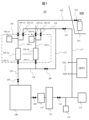
- FIG. 2 is a schematic diagram illustrating a processing gas introduction mechanism and exhaust mechanism of a microwave plasma etching apparatus having a single gas injection mechanism according to Example 1.
- FIG. 3 is a schematic diagram illustrating a processing gas introduction mechanism and exhaust mechanism of a microwave plasma etching apparatus having a multi-gas injection mechanism according to a second embodiment.
- FIG. 2 is a flowchart showing the operation flow of each valve in a cycle purge operation for explaining a gas exhaust method of the microwave plasma etching apparatus having a single gas injection mechanism according to the first embodiment.
- FIG. 7 is a flowchart showing the operation flow of each valve in a cycle purge operation for explaining a gas exhaust method of a microwave plasma etching apparatus having a multi-gas injection mechanism according to a second embodiment.
- FIG. 1 is a schematic diagram illustrating a processing gas introduction mechanism and exhaust mechanism of a microwave plasma etching apparatus having a single gas injection mechanism according to Example 1.
- FIG. 3 is a flowchart showing the operation flow of each valve in a cycle purge operation to explain the gas exhaust method of the microwave plasma etching apparatus having a single gas injection mechanism according to the first embodiment.
- a microwave plasma etching apparatus (hereinafter also referred to as an etching apparatus) 10, which is a plasma processing apparatus, will be described as an example of a semiconductor manufacturing apparatus.
- a microwave plasma etching apparatus 10 having a single gas injection mechanism will be explained using FIGS. 1 and 3.
- FIG. The single gas injection mechanism means a configuration in which there is only one gas supply portion to the processing chamber 108 of the etching processing apparatus 10.
- the etching processing apparatus 10 includes a processing chamber 108 in which samples such as semiconductor wafers are subjected to plasma processing, a high frequency power source (RF bias power source) that supplies high frequency power for generating plasma, and a sample stage on which the sample is placed. , a gas supply mechanism that supplies gas to the processing chamber 108, and an exhaust device that exhausts the gas.
- RF bias power source high frequency power source
- a gas cylinder 101 that is a gas supply source is connected to a gas pipe 102 that is a gas supply pipe, and a path for supplying gas into a processing chamber 108 is used as a gas supply mechanism.
- a gas pipe provided between the gas cylinder 101 and the processing chamber 108 is referred to as a gas pipe 102.
- a valve 103 and a valve 105 are arranged on the path of the gas pipe 102 to open or shut off the flow path inside the gas pipe 102. 102 channels are opened and closed.
- the gas cylinder 101 and the valve 103 can be said to be facilities on the semiconductor manufacturing factory 500 side.
- the components other than the gas cylinder 101 and the valve 103 are the components provided in the etching apparatus 10.
- the mass flow controller box 104 that is an introduction path for a plurality of gases on the upstream side of the valve 105.
- the mass flow controller box 104 can be referred to as a gas flow rate control device.
- the flow controller box 104 includes n gas paths, gas lines 104-1 to 104-n, through which gases of different elements or substances of different compositions (different types) flow. Gases of different types flowing through the plurality of gas lines 104-1 to 104-n are mixed at the confluence section to become a processing gas, which flows through the inside of the gas pipe 102 toward the processing chamber 108.
- the processing gas introduced into the processing chamber 108 is exhausted by the operation of the turbo molecular pump 111 and the dry pump 114, which are vacuum pumps serving as exhaust devices.
- the amount and speed of the exhausted gas vary depending on the rotation speed of the turbo-molecular pump 111 and the area of the opening according to the angle of the variable conductance valve 110. Further, the pressure value and degree of vacuum within the processing chamber 108 are adjusted by balancing the amount and speed of processing gas supply and the amount and speed of exhaust from the variable conductance valve 110.
- a valve 109 is provided between the processing chamber 108 and the variable conductance valve 110, and a valve 112 is provided between the turbomolecular pump 111 and the dry pump 114.
- each of the gas lines 104-1 to 104-n mass flow controllers 104-1b to 104-nb, which are regulators that variably increase or decrease the flow rate and speed of the gas flowing therein, are arranged. Valves 104-1a to 104-1a and valves 104-1c to nc are arranged to open or shut off each of -1 to n, respectively. Furthermore, each of the gas lines 104-1 to 104-n, which are internal gas piping, is connected to the gas cylinder 101, which is a gas supply source, on the upstream side. Each of the gas lines 104-1 to 104-n is provided with first pressure gauges 104-1e to 104-ne for monitoring the pressure of the gas cylinder 101. A valve 105 is arranged between the valves 104-1c to nc and the processing chamber 108.
- bypass lines 118 and 115 which are exhaust pipes, are connected between the gas lines 104-1 to 104-n on the path of the gas pipe 102 or the confluence section where the mass flow controller box 104 joins, and the valve 105.
- the bypass line 115 includes a connection portion with a bypass line 117, which is an exhaust pipe connected at one end to the inlet of the dry pump 114.
- a valve 106 is provided on the path of the bypass lines 118 and 115 to open or shut off the internal flow path.
- Each of the gas lines 104-1 to 104-n includes a purge line 116, which is a gas purge path connected to the bypass line 117, and an internal flow path is provided on each of the purge lines 116. It is equipped with valves 104-1d to 104-nd that open or shut off.
- the dry pump 114 is normally an exhaust pump connected to the exhaust port of the turbomolecular pump 111.
- the turbo molecular pump 111 is capable of evacuating the gas piping 102, flow controller box 104, gas lines 104-1 to 104-n, or the processing chamber 108 in a relatively high pressure range that cannot be evacuated due to low exhaust efficiency. Can not. Therefore, an internal flow path is opened or blocked on the line path connecting the turbo molecular pump 111 and the inlet of the dry pump 114, and on the turbo molecular pump 111 side from the connecting part to which the bypass line 117 connects.
- a valve 112 is placed.
- a second pressure gauge 113 is provided between the valve 112 and the dry pump 114.
- the turbo molecular pump 114 is operated from the bypass line 117 to the gas piping 102, the flow controller box 104, the gas lines 104-1 to 104-n, or the inside of the processing chamber 108 from atmospheric pressure.
- the vacuum can be efficiently evacuated to a usable high degree of vacuum (the roughing line of the processing chamber 106 is not shown).
- a valve 107 is arranged on the path between the purge line 116 and the bypass line 117 to open or shut off a flow path inside the bypass line 117.
- the etching apparatus 10 has a control device CNT1, and controls valves 103, valves 104-1a to na, mass flow controllers 104-1b to nb, valves 104-1c to nc, and valve 104-1d according to control signals CS1 to CSm. ⁇ nd, the opening and closing operations of the valves 105-107, 109, and 112, the variable conductance valve 110, and the operations of the turbo molecular pump 111 and the dry pump 114 can be controlled.
- the control device CNT1 is capable of acquiring measured values of the mass flow controllers 104-1b to 104-nb, and is also connected to the pressure gauges 104-1e to 104-ne, 113 to measure The pressure value can be obtained.
- the control device CNT1 can execute the sequence shown in FIG. 3 and automatically control the opening and closing of each valve according to the sequence shown in FIG.
- the control device CNT1 is a high-frequency power source that controls on and off of the microwave power source, controls the frequency, and supplies high-frequency power for generating plasma based on input settings (also referred to as recipes) by an input means. It is possible to perform on/off control of the RF bias power source, frequency control, and parameter control of the microwave power source and the RF bias power source.
- the control unit 122 can further control etching parameters such as the flow rate of gas for performing etching, processing pressure, coil current, temperature of the sample stage on which the sample is placed, and etching time.
- the control device CNT1 divides the gas in the gas piping 104-1 filled from the gas cylinder 101 and exhausts it in stages.
- the sequence of FIG. 3 for terminating the evacuation of is executed.
- the valve 103 which is the main valve of the gas cylinder 101, is open, the sequence shown in FIG. 3 is executed by the control device CNT1.
- valve 103 disposed between the gas cylinder 101 and the gas connection valve 104-1a on the upper side of the mass flow controller box 104 is kept open (valve 104-1a is kept open).
- the mass flow controller 104-1b is open, and the valve 105 between the valve 104-1c and the processing chamber 108 is closed.
- the valve 104 is located between the gas cylinder 101 and the mass flow controller 104-1b. -1a is closed (301).
- the gas pipe 102 including the gas line 104-1 is filled with the gas from the gas cylinder 101.
- (301) can be called a filling step.
- the filling step can also include (301), and (309) and (310), which will be described later.
- valve 112 disposed between the dry pump 114 and the processing chamber 108 is closed in order to exhaust the metal contamination source remaining in the gas pipes 102, 104-1 without going through the processing chamber 108 of the etching processing apparatus 10.
- valve 109 disposed between the processing chamber 108 and the variable conductance valve device 110 that controls the pressure within the processing chamber 108 is closed (302).
- valves 104-1c and 104-1d are opened to exhaust gas remaining in valve 104-1a, valve 104-1d (gas pipe 104-1), and valve 104-1c.
- the dry pump 114 exhausts the remaining gas from the valve 104-1a to the valve 104-1d (gas pipe 104-1) and the valve 104-1c via the gas pipes 115, 116, 117, and 118.
- Perform (304). (304) can be called an exhaust step.
- the evacuation step may also include (304), 302), and (303).
- the valves 107 and 106 are closed, and exhaustion using the dry pump 114 is ended (306). (305) and (306) can be called monitoring steps.
- the control device CNT1 ends the gas exhaust (exhaust step) based on the pressure measurement value of the pressure gauge 113 that measures the exhaust pressure of the dry pump 114 and the pressure measurement value of the pressure gauge 104-1e that measures the gas pressure of the gas cylinder 101.
- the valves 112 and 109 are opened (307), and the processing of the etching processing apparatus 10 is continued for a predetermined period of time.
- the chamber 108 is evacuated (308).
- (307, 308) can be said to be a processing chamber exhaust step.
- the turbo molecular pump 111 or the dry pump 114 can be used for exhausting the processing chamber exhaust step (307, 308).
- the valve 104-1a is opened, and gas is filled from the valve 104-1a into the gas pipe 104-1 between the valve 104-1d and the mass flow controller 104-1b (309).
- the valve 104-1a is opened, and after one second, the mass flow controller 104-1b is fully opened (310).
- the present invention is a sequence in which gas filling (filling step), exhausting (exhaust step), and monitoring (monitoring step) are repeated, the number of cycles n (n is a positive integer) performed in (311) It is determined whether or not the number of cycles has reached a specified number of cycles N (N is a positive integer). (311) can be said to be a repeating step. If the number of executed cycles n has not reached the specified number of cycles N in (311) (n ⁇ N, 311: No), the process returns to (301), and the filling sequence (filling step) explained in (301-311), exhaust The sequence (exhaust step) and monitoring (monitoring step) are repeated a specified number of cycles (N times).
- the process moves to (312).
- metal contamination sources such as metals (Cr, Fe) remaining in the gas piping (102) are removed through the exhaust piping (115, 116, 117, 118) of the plasma processing apparatus 10.
- the filled gas can be exhausted to the outside of the plasma processing apparatus 10 by a dry pump (114).
- the specified number of cycles (predetermined number of times) N is calculated by calculating the ratio of the length of the gas pipe 104-1 from the valve 104-1a to the valve 104-1c and the length of the gas pipe 102 from the gas cylinder 101 to the valve 104-1a. This is the number of times determined by
- a judgment step (312) is executed to judge whether the specified gas type has been used.
- (312) it is determined whether the specified gas type has ended or not, and if the specified gas type has ended (312: YES), this sequence ends. On the other hand, if the specified gas type has not been completed (312: No), the process moves to (301). Then, switching to another specified gas type, steps (301-311) are repeated. In other words, if you want to perform other gas types, return to (301) again after the above-mentioned gas filling sequence and exhaust sequence (301-311), and perform the same operation as (301-311) for other gas types. repeat.
- control device CNT1 divides the gas in the gas pipes 102 and 104-1 filled from the gas cylinder 101 from the waste pipe 116 side and the gas pipe 118 side and exhausts it in stages, and exhausts the gas in the dry pump 114 in stages.
- the sequence shown in FIG. 3 is executed to terminate gas exhaust based on the exhaust pressure (measured by the pressure gauge 113) and the gas pressure in the gas cylinder 101 (measured by the pressure gauge 104-1e).
- the gas filled in the gas cylinder 101 is exhausted in stages, and the gas is evacuated based on the pressure on the exhaust side of the exhaust device (114) and the gas pressure in the gas cylinder 101.
- valve opening and closing is automatically performed by the control device CNT1 that executes the sequence shown in FIG. Therefore, it is possible to respond 24 hours a day even in the absence of an operator, and since human errors do not occur, it is possible to suppress the occurrence of gas contamination.
- gases within the same category of combustible gas and combustion-supporting gas can be selected at the same time, reducing exhaust time. If gases of the same category are filled in the gas lines 104-1, 104-2, 104-3 in the filling step, the gases filled in the gas lines 104-1, 104-2, 104-3 in the exhaust step can be evacuated simultaneously by dry pump 114 via lines 116, 118, and 117. Therefore, metal contamination sources caused by gas piping can be reduced in a short time.
- valve opening/closing is automatically performed by the control device CNT1 that executes the sequence shown in FIG. 3, but it is of course possible to have the operator execute the sequence shown in FIG. .
- FIG. 2 is a schematic diagram illustrating a processing gas introduction mechanism and exhaust mechanism of a microwave plasma etching apparatus having a multi-gas injection mechanism according to a second embodiment.
- FIG. 4 is a flowchart showing the operation flow of each valve in a cycle purge operation to explain a gas exhaust method of a microwave plasma etching apparatus having a multi-gas injection mechanism according to the second embodiment.
- a microwave plasma etching apparatus (hereinafter referred to as an etching processing apparatus) 11 having a multi-gas injection mechanism will be described with reference to FIGS. 2 and 4.
- the multi-gas injection mechanism refers to a configuration in which there are multiple (two in FIG. 2) gas supply sections to the processing chamber 209 of the etching processing apparatus 11.
- the etching apparatus 11 includes a gas cylinder 201 as a gas supply source connected to a gas pipe 202, and a path for supplying gas into a processing chamber 209.
- a gas pipe provided between a gas cylinder 201 and a processing chamber 209 is a gas pipe 202 .
- a valve 203 and valves 205 and 215 are arranged on the path of the gas pipe 202 to open or shut off the flow path inside the gas pipe 202.
- the flow path of the gas pipe 202 is opened and closed accordingly.
- the gas cylinder 201 and the valve 203 can be said to be facilities on the semiconductor manufacturing factory 500 side.
- the components other than the gas cylinder 201 and valve 203 are the components provided in the etching apparatus 11.
- the flow controller box 204 includes n gas paths, gas lines 204-1 to 204-n, through which gases of different elements or substances of different compositions (different types) flow. Different types of gases flowing through the plurality of gas lines 204-1 to 204-n become a mixed processing gas at the confluence section, and flow through the inside of the gas pipe 202 toward the processing chamber 209.
- the processing gas introduced into the processing chamber 209 is exhausted by the operation of the turbo molecular pump 211 and the dry pump 214, which are vacuum pumps.
- the amount and speed of the exhausted gas vary depending on the rotation speed of the turbomolecular pump 211 and the area of the opening according to the angle of the variable conductance valve 210. Further, the pressure value and degree of vacuum within the processing chamber 209 are adjusted by balancing the amount and speed of processing gas supply and the amount and speed of exhaust from the variable conductance valve 210.
- a valve 212 is provided between the turbomolecular pump 211 and the dry pump 214.
- mass flow controllers 204-1b to 204-nb which are regulators that variably increase or decrease the flow rate and speed of the gas flowing therein, are arranged.
- Valves 204-1a to 204-na, valves 204-1c to nc, and valves 204-1f to nf are arranged to open or shut off each of -1 to -n, respectively.
- each of the gas lines 204-1 to 204-n is connected to a gas cylinder 201, which is a gas supply source, on the upstream side.
- First pressure gauges 204-1e to 204-ne for monitoring the pressure of the gas cylinder 201 are provided in each of the gas lines 204-1 to 204-n.
- a valve 205 is arranged between the valves 204-1c to nc and the processing chamber 209, and a valve 215 is arranged between the valves 204-1f to nf and the processing chamber 209.
- bypass lines 218 and 216 are connected between the valves 205 and 215 and the gas lines 204-1 to 204-n on the path of the gas pipe 202 or the merging section where the flow controller box 204 joins.
- the bypass line 216 includes a connection portion between the inlet of the dry pump 214 and a bypass line 218 connected at one end.
- a valve 206 is provided on the path of the bypass line 216 to open or shut off the internal flow path.
- Each of the gas lines 204-1 to 204-n includes a purge line 217, which is a gas purge path connected to the bypass line 218, and an internal flow path is provided on each of the purge lines 217. It is equipped with valves 204-1d to 204-nd that open or shut off.
- the dry pump 214 is normally an exhaust pump connected to the exhaust port of the turbomolecular pump 211.
- the turbo molecular pump 211 is capable of evacuating the gas piping 202, flow controller box 204, gas lines 204-1 to 204-n, or the processing chamber 209 in a relatively high pressure range that cannot be evacuated due to low exhaust efficiency. Can not. Therefore, an internal flow path is opened or blocked on the line path connecting the turbo molecular pump 211 and the inlet of the dry pump 214, and on the side of the turbo molecular pump 211 from the connecting part to which the bypass line 218 connects.
- a valve 212 is placed.
- a second pressure gauge 213 is provided between the valve 212 and the dry pump 214.
- the turbo molecular pump 214 is operated from atmospheric pressure to the gas piping 202, the flow controller box 204, the gas lines 204-1 to 204-n, or the inside of the processing chamber 209 from the bypass line 218. It is possible to efficiently evacuate to a reduced pressure state with a usable high degree of vacuum (the roughing line of the processing chamber 209 is not shown). Note that valves 207 and 208 are arranged on the path of the purge line 217 and the bypass line 218 to open or shut off the flow path inside the bypass line 218.
- the etching apparatus 11 has a control device CNT2, and controls valves 203, valves 204-1a to na, mass flow controllers 204-1b to nb, valves 204-1c to nc, and valve 204-1d according to control signals CS1 to CSm. -nd, valves 204-1f to nf, valves 205-208, 212, variable conductance valve 210, turbo molecular pump 211, and dry pump 214 can be controlled. Further, the control device CNT2 is connected to the pressure gauges 204-1e to 204-ne and 213, and can obtain the measured pressure values.
- the control device CNT1 can execute the sequence shown in FIG. 4 and automatically control the opening and closing of each valve according to the sequence shown in FIG.
- the control device CNT2 controls the on and off of the microwave power supply, the frequency control, the on and off control of the RF bias power supply, and the frequency control based on the input settings (also called recipes) by the input means.
- control of the parameters of the microwave power source and the RF bias power source can be implemented.
- the control unit 122 can further control etching parameters such as gas flow rate, processing pressure, coil current, sample stage temperature, and etching time for performing etching.
- valve 203 disposed between the gas cylinder 201 and the gas connection valve 204-1a of the mass flow controller box 204 remains open (valve 204-1a is in the open state, and the mass flow controller 204-1b is in the open state).
- the valve 204-1a located between the gas cylinder 201 and the mass flow controller 204-1b is closed. 401).
- gas from the gas cylinder 201 is filled into the gas pipe 202 including the gas line 204-1.
- (401) can be called a filling step.
- the filling step can also include (401), and (409) and (410), which will be described later.
- the valve 212 disposed between the dry pump 214 and the processing chamber 209 is closed, and the The chamber 209 and the variable conductance valve device 210 that controls the pressure within the processing chamber 209 are closed (402).
- valves 204-1c and 204-1f in order to exhaust gas remaining from valve 204-1a in mass flow controller box 204 to valve 204-1d and valve 204-1c, and from valve 204-1c to valve 204-1f.
- valve 204-1f is in a closed state. Note that the valve 204-1f may be in an open state.
- the dry pump 214 connects the valve 104-1a to the valve 104-1d (inside the gas pipe 104-1), the valve 104-1c, and the valve 204-1c to the valve 204-1 through the gas pipes 216, 217, and 218.
- the gas remaining in 1f is exhausted (404).
- (404) can be called an exhaust step.
- the evacuation step may also include (404), (402), and (403).
- the control device CNT2 ends the gas exhaust (exhaust step) based on the pressure measurement value of the pressure gauge 213 that measures the exhaust pressure of the dry pump 114 and the pressure measurement value of the pressure gauge 204-1e that measures the gas pressure of the gas cylinder 201.
- valve 212 and the variable conductance valve device 210 are opened (407), and the inside of the processing chamber 209 is evacuated for a predetermined period of time ( 408).
- (407, 408) can be said to be a processing chamber exhaust step.
- the turbo molecular pump 111 or the dry pump 114 can be used for exhausting the processing chamber exhaust step (407, 408).
- the valve 204-1a is opened, and gas is filled from the valve 204-1a into the space between the valve 204-1d and the mass flow controller 204-1b (inside the gas pipe 204-1) (409).
- the valve 204-1c and valve 204-1f in order to fill the valve 204-1a, and after 1 second, fully open the mass flow controller 104-1b. (410).
- the specified number of cycles (predetermined number of times) N is calculated by calculating the ratio of the length of the gas pipe 104-1 from the valve 104-1a to the valve 104-1c and the length of the gas pipe 102 from the gas cylinder 101 to the valve 104-1a. This is the number of times determined by
- a judgment step (412) is executed to judge whether the specified gas type has been used.
- metal contamination sources present in the gas pipes 202 and 204-1 can be reduced.
- control device CNT2 divides and exhausts the gas in the gas pipes 202 and 204-1 filled from the gas cylinder 201, and increases the exhaust pressure of the dry pump 214 (measured by the pressure gauge 213) and the gas in the gas cylinder 201.
- the sequence shown in FIG. 4 is executed to terminate gas exhaust based on the pressure (measured by pressure gauge 204-1e).
- the etching processing apparatus 11 is a multi-gas injection mechanism, the same effects as in the first embodiment can be obtained.
- valve opening/closing is automatically performed by the control device CNT2 that executes the sequence shown in FIG. 4, but it is of course possible to have the operator execute the sequence shown in FIG. .
- 306, 311) further comprises a control device (CNT1).
- the gas supply mechanism includes a first valve (104-1a) disposed between the gas cylinder (101) and a gas flow rate control device (104), and a gas filled from the gas cylinder (101) to the processing chamber. (108), a second valve (107) disposed on the piping (117) for exhausting air without going through the 3 valve (104-1c),
- the gas filled from the gas cylinder (101) is exhausted a predetermined number of times according to the sequence,
- the predetermined number of times is the number of times from the first valve (104-1a) to the third valve (104) with respect to the length of the piping (102) from the gas cylinder (101) to the first valve (104-1a).
- a plasma processing apparatus characterized in that the number of times is determined based on the ratio of the lengths of the piping (104-1) to -1c).
- Plasma processing characterized in that the control device (CNT1) ends exhausting the gas when the pressure on the exhaust side of the exhaust device (114) and the gas pressure in the gas cylinder (101) become approximately equal. Device.
- a plasma processing apparatus characterized in that the pressure on the exhaust side of the exhaust device (114) is a pressure between a turbo molecular pump (111) and a dry pump (114).
- a plasma processing apparatus characterized in that the sequence is executed by the control device (CNT1) when the main valve of the gas cylinder (101) is open.
- a plasma processing apparatus characterized in that the sequence is executed by the control device (CNT1) when the main valve of the gas cylinder (101) is open.
- Gas filled in a gas cylinder (101) is evacuated in stages, and the gas evacuation is terminated based on the pressure on the exhaust side of an exhaust device (114) and the gas pressure in the gas cylinder (101). Exhaust method.
- the plasma processing equipment is a first valve (104-1a) disposed between the gas cylinder (101) and the mass flow controller (104-1b); a second valve (107) for exhausting the filled gas from the dry pump (114) side; a third valve (104-1c) disposed downstream of the mass flow controller (104-1b); a fourth valve (106) for exhausting the gas filled in the third valve (104-1c) side; a first pressure gauge (104-1e) that is provided between the first valve (104-1a) and the mass flow controller (104-1b) and monitors the pressure of the gas cylinder (101); a second pressure gauge (113) disposed between the dry pump (114) and the turbomolecular pump (111); A control device (CNT1), The control device (CNT1) is a filling step (301) of filling gas from the gas cylinder (101) to the third valve (104-1c) and closing the first valve (104-1a); After the filling step (301), opening the second valve (107) and the fourth valve (106) (303) and exhausting the filled gas (
- the predetermined number of times is calculated by calculating the ratio of the length of the gas pipe (104-1) from the first valve to the third valve and the length of the gas pipe (102) from the gas cylinder to the first valve. This is the number of times requested.
- the control device (CNT1) is In the filling step, the exhaust step and the monitoring step, the fifth valve (105) is in a closed state; In the filling step, the sixth valve (104-1d) is closed, In the exhaust step, the sixth valve (104-1d) is opened.
- the control device (CNT1) is After the monitoring step, the seventh valve (109) and the eighth valve (112) are opened, and the processing chamber (108) is operated by the dry pump (114) and the turbomolecular pump (111).
- a process chamber exhaust step (307, 308) is executed.
- the control device (CNT1) is After the process chamber exhaust step (307, 308), the first valve (104-1a) and the mass flow controller (104-1b) are opened, and then the repeat step (311) is executed.
- the control device (CNT1) is After the repeating step (311), executing a determining step (312) for determining whether or not the specified gas type has been used; When the specified gas type is completed, the filling step, the exhaust step, and the monitoring step are completed; If the specified gas type has not been completed, the system switches to another specified gas type and executes the filling step, the exhaust step, and the monitoring step.
- a ninth valve (104-1f) provided between the mass flow controller (104-1b) and the processing chamber (108); a tenth valve (215) provided between the ninth valve (104-1f) and the processing chamber (108),
- the space between the ninth valve (104-1f) and the tenth valve (215) can be evacuated by the dry pump (114) via the second valve (107),
- the control device (CNT1) is In the monitoring step, the fifth valve (105) and the tenth valve (215) are closed; In the filling step, the sixth valve (104-1d) is closed, In the exhaust step, the sixth valve (104-1d) is opened.
Landscapes
- Physics & Mathematics (AREA)
- Engineering & Computer Science (AREA)
- Plasma & Fusion (AREA)
- Chemical & Material Sciences (AREA)
- Analytical Chemistry (AREA)
- Drying Of Semiconductors (AREA)
- Plasma Technology (AREA)
Priority Applications (6)
| Application Number | Priority Date | Filing Date | Title |
|---|---|---|---|
| KR1020237021673A KR102864350B1 (ko) | 2022-05-18 | 2022-05-18 | 플라스마 처리 장치 및 가스의 배기 방법 |
| JP2023535740A JP7543566B2 (ja) | 2022-05-18 | 2022-05-18 | プラズマ処理装置およびガスの排気方法 |
| PCT/JP2022/020737 WO2023223481A1 (ja) | 2022-05-18 | 2022-05-18 | プラズマ処理装置およびガスの排気方法 |
| US18/279,460 US20250069867A1 (en) | 2022-05-18 | 2022-05-18 | Plasma processing apparatus and gas exhaust method |
| CN202280008559.1A CN117425950A (zh) | 2022-05-18 | 2022-05-18 | 等离子处理装置以及气体的排气方法 |
| TW112106937A TWI864615B (zh) | 2022-05-18 | 2023-02-24 | 電漿處理裝置及氣體之排氣方法 |
Applications Claiming Priority (1)
| Application Number | Priority Date | Filing Date | Title |
|---|---|---|---|
| PCT/JP2022/020737 WO2023223481A1 (ja) | 2022-05-18 | 2022-05-18 | プラズマ処理装置およびガスの排気方法 |
Publications (1)
| Publication Number | Publication Date |
|---|---|
| WO2023223481A1 true WO2023223481A1 (ja) | 2023-11-23 |
Family
ID=88834910
Family Applications (1)
| Application Number | Title | Priority Date | Filing Date |
|---|---|---|---|
| PCT/JP2022/020737 Ceased WO2023223481A1 (ja) | 2022-05-18 | 2022-05-18 | プラズマ処理装置およびガスの排気方法 |
Country Status (6)
| Country | Link |
|---|---|
| US (1) | US20250069867A1 (https=) |
| JP (1) | JP7543566B2 (https=) |
| KR (1) | KR102864350B1 (https=) |
| CN (1) | CN117425950A (https=) |
| TW (1) | TWI864615B (https=) |
| WO (1) | WO2023223481A1 (https=) |
Families Citing this family (1)
| Publication number | Priority date | Publication date | Assignee | Title |
|---|---|---|---|---|
| WO2025136713A1 (en) * | 2023-12-20 | 2025-06-26 | Lam Research Corporation | In-situ calibration of gas flows in substrate processing systems |
Citations (3)
| Publication number | Priority date | Publication date | Assignee | Title |
|---|---|---|---|---|
| JPH04180567A (ja) * | 1990-11-15 | 1992-06-26 | Nec Kyushu Ltd | 半導体製造装置の材料ガス供給システム |
| JP2012238772A (ja) * | 2011-05-13 | 2012-12-06 | Sharp Corp | 反応室開放方法、及び気相成長装置 |
| JP2017084882A (ja) * | 2015-10-23 | 2017-05-18 | 株式会社日立ハイテクノロジーズ | 半導体製造装置のガス排気方法 |
Family Cites Families (4)
| Publication number | Priority date | Publication date | Assignee | Title |
|---|---|---|---|---|
| JP3705204B2 (ja) * | 2001-12-27 | 2005-10-12 | ソニー株式会社 | 気相成長装置及び発光素子の製造装置 |
| JP4606396B2 (ja) * | 2006-09-15 | 2011-01-05 | 東京エレクトロン株式会社 | 処理ガス供給システム及び処理ガス供給方法 |
| JP4961223B2 (ja) * | 2007-01-31 | 2012-06-27 | 株式会社日立ハイテクノロジーズ | プラズマ処理装置の圧力制御方法 |
| CN114256086A (zh) * | 2020-09-24 | 2022-03-29 | 中国科学院微电子研究所 | 一种半导体反应腔的气路系统、控制方法及加工设备 |
-
2022
- 2022-05-18 CN CN202280008559.1A patent/CN117425950A/zh active Pending
- 2022-05-18 JP JP2023535740A patent/JP7543566B2/ja active Active
- 2022-05-18 KR KR1020237021673A patent/KR102864350B1/ko active Active
- 2022-05-18 WO PCT/JP2022/020737 patent/WO2023223481A1/ja not_active Ceased
- 2022-05-18 US US18/279,460 patent/US20250069867A1/en active Pending
-
2023
- 2023-02-24 TW TW112106937A patent/TWI864615B/zh active
Patent Citations (3)
| Publication number | Priority date | Publication date | Assignee | Title |
|---|---|---|---|---|
| JPH04180567A (ja) * | 1990-11-15 | 1992-06-26 | Nec Kyushu Ltd | 半導体製造装置の材料ガス供給システム |
| JP2012238772A (ja) * | 2011-05-13 | 2012-12-06 | Sharp Corp | 反応室開放方法、及び気相成長装置 |
| JP2017084882A (ja) * | 2015-10-23 | 2017-05-18 | 株式会社日立ハイテクノロジーズ | 半導体製造装置のガス排気方法 |
Also Published As
| Publication number | Publication date |
|---|---|
| TW202347494A (zh) | 2023-12-01 |
| KR102864350B1 (ko) | 2025-09-24 |
| US20250069867A1 (en) | 2025-02-27 |
| JPWO2023223481A1 (https=) | 2023-11-23 |
| CN117425950A (zh) | 2024-01-19 |
| JP7543566B2 (ja) | 2024-09-02 |
| TWI864615B (zh) | 2024-12-01 |
| KR20230161932A (ko) | 2023-11-28 |
Similar Documents
| Publication | Publication Date | Title |
|---|---|---|
| JP6037707B2 (ja) | プラズマ処理装置及びプラズマ処理装置の診断方法 | |
| US12241772B2 (en) | Flow metrology calibration for improved processing chamber matching in substrate processing systems | |
| KR20170040768A (ko) | 가스 분석을 위한 국소 환경의 생성 | |
| JP4417434B2 (ja) | 真空プロセッサの圧力を制御する方法及び装置 | |
| WO2023223481A1 (ja) | プラズマ処理装置およびガスの排気方法 | |
| US8569177B2 (en) | Plasma processing apparatus and plasma processing method | |
| CN113441487B (zh) | Mo源管路及其清洗方法 | |
| CN119768907A (zh) | 用于控制前级管道压力的系统及方法 | |
| KR102806119B1 (ko) | 기판 가스방출을 관리하기 위한 장치 | |
| US20240339338A1 (en) | Wafer processing apparatus for combined high-pressure process and vacuum process, and wafer processing method using decompression | |
| JP7642869B2 (ja) | 真空ポンプシステムのための流体ルーティング | |
| JP7720409B2 (ja) | 真空ポンプシステム用バルブモジュール | |
| JP7681723B2 (ja) | 半導体処理システム | |
| JP7168794B2 (ja) | プラズマ処理装置の検査方法 | |
| JP5008086B2 (ja) | 調圧機能付高速ガス切替装置 | |
| TW202412130A (zh) | 用於半導體晶圓處理工具的系統及製造半導體晶圓的方法 | |
| JPH09306851A (ja) | 減圧排気システムおよび減圧気相処理装置 | |
| US20250266268A1 (en) | Fluid routing for a vacuum pumping system | |
| TWI922672B (zh) | 真空泵送系統、用於該真空泵送系統之流體路徑模組、及操作用於該真空泵送系統之該流體路徑模組之方法 | |
| JP2010283211A (ja) | プラズマ処理装置 | |
| CN121137550A (zh) | 氮气置换装置及化学气相沉积设备 |
Legal Events
| Date | Code | Title | Description |
|---|---|---|---|
| ENP | Entry into the national phase |
Ref document number: 2023535740 Country of ref document: JP Kind code of ref document: A |
|
| WWE | Wipo information: entry into national phase |
Ref document number: 202280008559.1 Country of ref document: CN |
|
| WWE | Wipo information: entry into national phase |
Ref document number: 18279460 Country of ref document: US |
|
| 121 | Ep: the epo has been informed by wipo that ep was designated in this application |
Ref document number: 22942686 Country of ref document: EP Kind code of ref document: A1 |
|
| NENP | Non-entry into the national phase |
Ref country code: DE |
|
| WWP | Wipo information: published in national office |
Ref document number: 18279460 Country of ref document: US |
|
| 122 | Ep: pct application non-entry in european phase |
Ref document number: 22942686 Country of ref document: EP Kind code of ref document: A1 |