WO2023218590A1 - Dispositif de commande, machine-outil et procédé de commande - Google Patents
Dispositif de commande, machine-outil et procédé de commande Download PDFInfo
- Publication number
- WO2023218590A1 WO2023218590A1 PCT/JP2022/020029 JP2022020029W WO2023218590A1 WO 2023218590 A1 WO2023218590 A1 WO 2023218590A1 JP 2022020029 W JP2022020029 W JP 2022020029W WO 2023218590 A1 WO2023218590 A1 WO 2023218590A1
- Authority
- WO
- WIPO (PCT)
- Prior art keywords
- collector
- processing
- mist
- control device
- control
- Prior art date
Links
- 238000000034 method Methods 0.000 title claims description 30
- 239000003595 mist Substances 0.000 claims abstract description 151
- 239000002826 coolant Substances 0.000 claims abstract description 91
- 238000003754 machining Methods 0.000 claims abstract description 50
- 230000008569 process Effects 0.000 claims description 12
- 230000005856 abnormality Effects 0.000 claims description 5
- 230000004048 modification Effects 0.000 description 11
- 238000012986 modification Methods 0.000 description 11
- 238000010586 diagram Methods 0.000 description 8
- NJPPVKZQTLUDBO-UHFFFAOYSA-N novaluron Chemical compound C1=C(Cl)C(OC(F)(F)C(OC(F)(F)F)F)=CC=C1NC(=O)NC(=O)C1=C(F)C=CC=C1F NJPPVKZQTLUDBO-UHFFFAOYSA-N 0.000 description 8
- 239000000428 dust Substances 0.000 description 4
- 238000009434 installation Methods 0.000 description 4
- 238000001914 filtration Methods 0.000 description 3
- 230000004044 response Effects 0.000 description 3
- 230000004913 activation Effects 0.000 description 2
- 230000005484 gravity Effects 0.000 description 2
- 239000012535 impurity Substances 0.000 description 2
- 238000011084 recovery Methods 0.000 description 2
- 230000008859 change Effects 0.000 description 1
- 238000005401 electroluminescence Methods 0.000 description 1
- 239000004973 liquid crystal related substance Substances 0.000 description 1
- 238000003801 milling Methods 0.000 description 1
Images


Classifications
-
- B—PERFORMING OPERATIONS; TRANSPORTING
- B23—MACHINE TOOLS; METAL-WORKING NOT OTHERWISE PROVIDED FOR
- B23Q—DETAILS, COMPONENTS, OR ACCESSORIES FOR MACHINE TOOLS, e.g. ARRANGEMENTS FOR COPYING OR CONTROLLING; MACHINE TOOLS IN GENERAL CHARACTERISED BY THE CONSTRUCTION OF PARTICULAR DETAILS OR COMPONENTS; COMBINATIONS OR ASSOCIATIONS OF METAL-WORKING MACHINES, NOT DIRECTED TO A PARTICULAR RESULT
- B23Q11/00—Accessories fitted to machine tools for keeping tools or parts of the machine in good working condition or for cooling work; Safety devices specially combined with or arranged in, or specially adapted for use in connection with, machine tools
-
- Y—GENERAL TAGGING OF NEW TECHNOLOGICAL DEVELOPMENTS; GENERAL TAGGING OF CROSS-SECTIONAL TECHNOLOGIES SPANNING OVER SEVERAL SECTIONS OF THE IPC; TECHNICAL SUBJECTS COVERED BY FORMER USPC CROSS-REFERENCE ART COLLECTIONS [XRACs] AND DIGESTS
- Y02—TECHNOLOGIES OR APPLICATIONS FOR MITIGATION OR ADAPTATION AGAINST CLIMATE CHANGE
- Y02P—CLIMATE CHANGE MITIGATION TECHNOLOGIES IN THE PRODUCTION OR PROCESSING OF GOODS
- Y02P70/00—Climate change mitigation technologies in the production process for final industrial or consumer products
- Y02P70/10—Greenhouse gas [GHG] capture, material saving, heat recovery or other energy efficient measures, e.g. motor control, characterised by manufacturing processes, e.g. for rolling metal or metal working
Definitions
- the present invention relates to a control device, a machine tool, and a control method.
- the mist collector collects mist generated within the processing area of the machine tool (see also Japanese Patent Application Laid-Open No. 2012-76006).
- the mist collector prevents mist from leaking outside the processing area by collecting the mist within the processing area.
- Mist is particulate coolant that floats in the air.
- the mist collector In order to reliably prevent mist from leaking outside the processing area, the mist collector is often operated for a long time. However, the mist collector consumes a large amount of power by operating for a long time.
- the present invention aims to solve the above-mentioned problems.
- a first aspect of the present invention is a machine tool that processes a workpiece in the processing area, and includes a coolant supply device that supplies coolant to a processing area, and a mist collector that collects mist in the processing area.
- the control device includes a processing control section that controls the machine tool to perform the processing based on a processing program and determines whether or not the processing has been completed, and a processing control unit that controls the mist when the processing is completed.
- the present invention is a control device including a collector control unit that automatically stops a collector.
- a second aspect of the present invention is a machine tool having the control device according to the first aspect.
- a third aspect of the present invention provides a machine tool that processes a workpiece in the processing area, and includes a coolant supply device that supplies coolant to a processing area, and a mist collector that collects mist in the processing area.
- a control method controlled by a computer comprising a completion determination step in which the computer determines whether or not the machining based on the machining program has been completed, and a step in which the computer controls the mist collector when the machining is completed.
- This control method includes a stop control step of automatically stopping the vehicle.
- the power consumption of the mist collector can be suppressed.
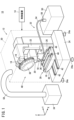
- FIG. 1 is a schematic diagram of a machine tool according to an embodiment.
- FIG. 2 is a block diagram of the control device.
- FIG. 3 is a flowchart showing the control method according to the embodiment.
- FIG. 4 is a schematic diagram of a machine tool according to Modification 1.
- FIG. 5 is a block diagram of a control device according to a second modification.
- FIG. 1 is a schematic diagram of a machine tool 10 according to an embodiment.
- the X direction and Y direction shown in FIG. 1 are directions parallel to the horizontal plane.
- the X direction and the Y direction are orthogonal to each other.
- the Z direction shown in FIG. 1 is a direction parallel to the direction of gravity. Therefore, the Z direction is orthogonal to the X direction and the Y direction.
- the Z direction shown in FIG. 1 indicates a direction opposite to the direction of gravity.
- the machine tool 10 includes a processing machine 12 and a control device 14.
- the processing machine 12 is a machine that processes a workpiece using a tool 16.
- the processing machine 12 includes a spindle 18, a spindle head 20, a column 22, a pedestal 24, a table 26, a table drive section 28, a cover 30, a coolant supply device 32, and a mist collector 34.
- a tool holder 36 is attached to the main shaft 18 (see FIG. 1).
- the tool holder 36 can be attached to and detached from the main shaft 18.
- Tool holder 36 holds tool 16.
- the tool 16 is, for example, a hail bit, a drill, an end mill, a milling cutter, or the like.
- the processing machine 12 further includes a tool magazine 38.
- the tool magazine 38 removably holds a plurality of tools 16.
- One tool 16 among the plurality of tools 16 held in the tool magazine 38 is replaceably attached to the tool holder 36.
- the spindle head 20 supports the spindle 18. Further, the spindle head 20 includes a motor that rotates the spindle 18. The tool 16 mounted on the spindle 18 via the tool holder 36 rotates together with the spindle 18.
- the column 22 supports the spindle head 20. Further, the column 22 includes a motor that moves the spindle head 20 in the Z direction. Column 22 is supported by pedestal 24.
- the pedestal 24 is installed on the installation surface.
- the installation surface is, for example, a factory floor.
- the installation surface may be a support surface of a stand provided on the floor.
- the installation surface extends parallel to the horizontal plane, for example.
- the pedestal 24 may include a plurality of legs 24a. Each leg 24a is, for example, a caster, a jack, or the like.
- the table drive unit 28 is supported by the pedestal 24.
- the table drive section 28 includes a first slide section 42, a saddle 44, and a second slide section 46.
- the first slide part 42 is installed on the pedestal 24.
- the first slide portion 42 includes, for example, a guide rail extending in the Y direction.
- the first slide portion 42 supports a saddle 44 .
- the saddle 44 moves in the Y direction in response to being driven by a motor (not shown).
- the motor is controlled by a control device 14.
- the saddle 44 moves while being guided by the first slide part 42. A more detailed explanation of the control device 14 will be given later.
- the second slide part 46 is provided on the saddle 44.
- the second slide portion 46 includes, for example, a guide rail extending in the X direction.
- the table 26 supports a workpiece (not shown) below the main shaft 18.
- the table 26 is supported by the second slide section 46.
- the table 26 moves in the X direction in response to being driven by a motor (not shown).
- the motor is controlled by a control device 14.
- the table 26 moves while being guided by the second slide section 46.
- the cover 30 covers the spindle 18, the spindle head 20, the column 22, the pedestal 24, the table 26, and the table drive section 28. Thereby, the cover 30 forms a processing area 48. The workpiece is processed within the processing area 48 .
- the cover 30 further includes a door (not shown) and a window (not shown).
- the operator can carry in workpieces into the processing area 48 through the open door. Further, the operator can easily check the condition inside the processing area 48 through the window.
- the coolant supply device 32 is a device that supplies coolant to the processing area 48.
- the coolant supply device 32 includes a coolant tank 50, a nozzle 52, a supply pipe 54, and a pump 56.
- the coolant tank 50 stores coolant.
- the coolant tank 50 is installed outside the processing area 48.
- the nozzle 52 is a discharge part that discharges coolant. Nozzle 52 is arranged within processing area 48 . Note that the coolant supply device 32 may include a plurality of nozzles 52.
- the supply pipe 54 is a pipe that connects the coolant tank 50 and the nozzle 52.
- the coolant supply device 32 may include a plurality of supply pipes 54.
- the number of supply pipes 54 is determined depending on the number of nozzles 52, for example.
- the supply pipe 54 passes through the cover 30 and connects the coolant tank 50 and the nozzle 52.
- the pump 56 is connected to the supply pipe 54.
- the pump 56 pumps up the coolant in the coolant tank 50 and sends it to the nozzle 52. As a result, coolant is discharged from the nozzle 52 into the processing area 48 . Note that the pump 56 is controlled by the control device 14.
- the coolant discharged into the machining area 48 cools the tool 16 and the workpiece.
- coolant mist is generated.
- the mist may leak out of the processing area 48 through the small gaps created in the processing machine 12.
- the mist collector 34 is a device that collects mist within the processing area 48.
- the mist collector 34 is installed outside the processing area 48. Further, the mist collector 34 is connected to the cover 30 via a duct 58.
- the mist collector 34 collects mist by sucking air within the processing area 48. This prevents mist from leaking out of the processing area 48.
- mist collector 34 may collect not only mist but also dust by suctioning the air within the processing area 48. This also prevents dust from leaking out of the processing area 48.
- the mist collector 34 may be connected to the coolant tank 50. Thereby, the mist collected by the mist collector 34 can be returned to the coolant tank 50 as coolant.
- mist collector 34 and the coolant tank 50 When connecting the mist collector 34 and the coolant tank 50, it is preferable that the mist collector 34 and the coolant tank 50 are connected via a filter (not shown).
- the filtration device removes impurities from the coolant sent from the mist collector 34 to the coolant tank 50.
- clean coolant By connecting the mist collector 34 and the coolant tank 50 via a filtration device, clean coolant can be returned from the mist collector 34 to the coolant tank 50.
- Impurities in the coolant are, for example, chips collected together with the mist.
- FIG. 2 is a block diagram of the control device 14.
- the control device 14 is a computer that controls the processing machine 12.
- the control device 14 is, for example, a numerical control device.
- the control device 14 includes a display section 60, an operation section 62, a storage section 64, a calculation section 66, and a backup power supply section 68.
- the display unit 60 is a display device including a display screen 60d.
- the display unit 60 is, for example, a liquid crystal display device or an OEL (Organic Electro-Luminescence) display device.
- the operation unit 62 is an input device that accepts instructions from an operator to the control device 14.
- the operation unit 62 includes, for example, an operation panel 62a, a touch panel 62b, and the like.
- the touch panel 62b is provided on the display screen 60d.
- the operation unit 62 (operation panel 62a) may include a keyboard, a mouse, and the like.
- the storage unit 64 may include a volatile memory (not shown) and a nonvolatile memory (not shown). Examples of volatile memory include RAM (Random Access Memory). Examples of the nonvolatile memory include ROM (Read Only Memory), flash memory, and the like. Data, etc. may be stored in volatile memory, for example. Programs, data tables, maps, etc. may be stored in non-volatile memory, for example. At least a portion of the storage unit 64 may be included in a processor, an integrated circuit, or the like as described above. The storage unit 64 stores a control program 70 and a machining program 72.
- the control program 70 is a program for causing the control device 14 to execute the control method according to the present embodiment. A more detailed explanation of the control method will be given later.
- the machining program 72 is a program that includes control instructions for the machining machine 12.
- the machining program 72 includes, for example, a plurality of control instructions for controlling each of the above-mentioned motors. Further, the machining program 72 includes, for example, a plurality of control instructions for controlling the coolant supply device 32.
- the machining program 72 is created or edited in advance by an operator.
- the calculation unit 66 may be configured by a processor such as a CPU (Central Processing Unit) or a GPU (Graphics Processing Unit). That is, the calculation unit 66 may be configured by a processing circuit.
- a processor such as a CPU (Central Processing Unit) or a GPU (Graphics Processing Unit). That is, the calculation unit 66 may be configured by a processing circuit.
- the calculation section 66 includes a processing control section 74 and a collector control section 76.
- the processing control section 74 and the collector control section 76 are realized by the calculation section 66 executing the control program 70.
- the processing control section 74 and the collector control section 76 may be realized by an integrated circuit such as an ASIC (Application Specific Integrated Circuit) or an FPGA (Field-Programmable Gate Array).
- the processing control section 74 and the collector control section 76 may be configured by an electronic circuit including a discrete device.
- the processing control unit 74 processes the workpiece by controlling the processing machine 12 based on the processing program 72.
- the machining control unit 74 controls the rotation of the spindle 18, the movement of the spindle head 20, and the movement of the table 26 based on the machining program 72.
- the mist collector 34 is controlled by the collector control section 76.
- the processing control unit 74 determines whether coolant is used in the processing performed by the processing machine 12 before cutting of the workpiece is started. This determination is made based on the machining program 72 or the operator's instructions.
- the machining program 72 includes a control command to start the coolant supply device 32.
- the processing control unit 74 determines that coolant is used in the processing performed by the processing machine 12. Further, for example, even if the machining program 72 does not include a control command to start the coolant supply device 32, the operator may instruct the control device 14 to start the coolant supply device 32. In this case, the processing control unit 74 determines that coolant is used in the processing performed by the processing machine 12.
- the machining control unit 74 determines whether machining based on the machining program 72 has been completed after the start of machining. For example, when all control commands necessary for processing the workpiece have been executed, the processing control unit 74 determines that the processing based on the processing program 72 has been completed.
- the collector control unit 76 determines whether or not to automatically start the mist collector 34 based on the determination result of whether coolant is used in the processing performed by the processing machine 12.
- the collector control unit 76 does not automatically start the mist collector 34. This prevents the mist collector 34 from operating unnecessarily when no mist is generated. Therefore, the power consumption of the mist collector 34 is suppressed.
- the collector control unit 76 controls the mist collector 34 to automatically start the mist collector 34.
- mist generated within the processing area 48 during processing can be collected by the mist collector 34.
- the mist collector 34 is automatically activated. Therefore, mist is prevented from leaking out of the processing area 48 due to human error.
- the collector control unit 76 preferably does not start the mist collector 34 until the processing is started. In other words, the collector control unit 76 preferably activates the mist collector 34 in response to the start of processing. This prevents the mist collector 34 from consuming power before mist is generated. In this case, the collector control unit 76 automatically starts the mist collector 34 when the operator instructs the control device 14 to start processing, for example. The collector control unit 76 may automatically start the mist collector 34 when the operator instructs the control device 14 to start the coolant supply device 32 .
- the collector control unit 76 determines whether or not to automatically stop the mist collector 34 based on the result of the determination as to whether or not the machining based on the machining program 72 has been completed. When the mist collector 34 is activated and the machining based on the machining program 72 is completed, the collector control unit 76 automatically stops the mist collector 34. This prevents the mist collector 34 from operating excessively after finishing machining due to, for example, human error.
- the collector control unit 76 stops the mist collector 34 after a predetermined time TM has elapsed since the end of processing. By intentionally continuing to operate the mist collector 34 even after the processing is completed, it is possible to prevent mist from being omitted from collection. Since the mist collector 34 is automatically stopped when the predetermined time TM has elapsed from the end of processing, the power consumption of the mist collector 34 is suppressed from becoming excessively large.
- the starting timing of the predetermined time TM is the time when the machining control unit 74 determines that the machining based on the machining program 72 has been completed. However, the collector control unit 76 may calculate (estimate) the end timing of the machining based on the machining program 72 based on the machining program 72. In that case, the collector control unit 76 may use the calculated end timing as the starting timing of the predetermined time TM.
- Information indicating the predetermined time TM is set in the control device 14 by an operator, for example. However, the information indicating the predetermined time TM may be set in the control device 14 by the manufacturer of the control device 14.
- the backup power supply section 68 is a power source different from the main power source of the control device 14.
- the backup power supply section 68 includes, for example, a battery.
- the backup power supply section 68 is built into the control device 14 .
- the backup power supply unit 68 may be provided in the machine tool 10 as an external power supply for the control device 14. Note that illustration of the main power source of the control device 14 is omitted.
- the backup power supply section 68 supplies power to each section of the control device 14.
- the collector control unit 76 can continue controlling the mist collector 34 even after the main power is turned off. Therefore, for example, the collector control unit 76 can automatically stop the mist collector 34 even after the main power is turned off.
- FIG. 3 is a flowchart illustrating the control method according to the embodiment.
- the control device 14 executes the control method illustrated in FIG. 3, for example.
- the control device 14 executes the control method shown in FIG. 3, for example, when machining is started. Note that at the start of the control method, the mist collector 34 is stopped.
- the control method in FIG. 3 includes a coolant use determination step S1, a start control step S2, a processing control step S3, an end determination step S4, a collector state determination step S5, and a stop control step S6.
- the processing control unit 74 determines whether coolant is used in the processing performed by the processing machine 12. As described above, the processing control unit 74 determines whether or not coolant is used in the processing performed by the processing machine 12 based on the processing program 72 or the operator's instructions.
- a startup control step S2 is started.
- the collector control unit 76 controls the mist collector 34 to automatically activate the mist collector 34.
- the processing control section 74 controls the processing machine 12 to process the workpiece.
- the processing control unit 74 controls the processing machine 12 based on the processing program 72.
- mist is generated within the processing area 48. However, since the mist is collected by the mist collector 34, it does not leak out of the processing area 48.
- the machining control unit 74 determines whether machining based on the machining program 72 has been completed. When the machining is completed (S4: YES), a collector state determination step S5 is started. If the machining is not completed (S4: NO), the machining control step S3 is continued.
- the collector control unit 76 determines whether the mist collector 34 is operating. If the mist collector 34 is operating (S5: YES), a stop control step S6 is started.
- the collector control unit 76 stops the mist collector 34.
- the collector control unit 76 may stop the mist collector 34 immediately, but it is preferable to stop the mist collector 34 after a predetermined time TM has elapsed since the end of processing.
- the control method of FIG. 3 ends when the stop control step S6 ends. Note that if the mist collector 34 is not operating (S5: NO), the stop control step S6 is skipped. In that case, the control method of FIG. 3 ends when the collector state determination step S5 ends.
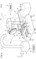
- FIG. 4 is a schematic diagram of a machine tool 101 (10) according to modification example 1.
- the machine tool 101 further includes a sub-control device 78.
- the sub-control device 78 is a computer separate from the control device 14.
- the sub-control device 78 includes, for example, a processor and a memory.
- Sub-controller 78 may include integrated circuits, discrete devices, and the like.
- the sub-control device 78 controls the mist collector 34 in place of the collector control unit 76 when the control device 14 stops. Therefore, even if the control device 14 stops, the mist collector 34 is controlled by the sub-control device 78 in the same manner as in the embodiment.
- the mist collector 34 collects the mist until the predetermined time TM has elapsed after the processing is completed. In such a case, the sub-control device 78 can control the mist collector 34 instead of the control device 14.
- the sub-control device 78 and the control device 14 communicate as appropriate and share data necessary for controlling the mist collector 34.
- the sub-control device 78 and the control device 14 share various information regarding the necessity of coolant during machining, the progress of machining, the elapsed time after machining is completed, and the like. Thereby, the sub-control device 78 can smoothly take over the control that was being performed by the collector control section 76. According to this modification, even after the control device 14 is stopped, the control of the mist collector 34 can be continued by the sub-control device 78.
- FIG. 5 is a block diagram of a control device 142 (14) according to the second modification.
- the control device 142 further includes an alarm output section 80.
- the alarm output unit 80 outputs an alarm when an abnormality occurs in the machine tool 10.
- the machine tool 10 is appropriately equipped with sensors (not shown) for detecting failures in various parts such as the spindle 18, the spindle head 20, and the table drive section 28.
- the alarm output unit 80 determines whether a failure has occurred in the machine tool 10 based on the signal output by the sensor. When a failure in each part of the machine tool 10 is detected, the alarm output section 80 notifies the operator of the occurrence of the failure, for example, via the display section 60.
- the machining control unit 74 does not start machining until the cause of the alarm is resolved. Furthermore, if the alarm output unit 80 outputs an alarm after the start of machining, the machining control unit 74 suspends the machining based on the machining program 72 until the cause of the alarm is resolved.
- the collector control unit 76 prohibits the operation of the mist collector 34 until the cause of the alarm is eliminated. If the mist collector 34 is in operation at the time the alarm is output, the collector control unit 76 stops the mist collector 34 regardless of the machining program 72 and the operator's instructions.
- the mist collector 34 is prevented from operating when an abnormality occurs in the machine tool 10.
- the collector control unit 76 may decide whether to start the mist collector 34 after starting processing. In that case, the collector control unit 76 acquires information indicating the ejection time during processing.
- the discharge time is the time during which the coolant is discharged into the machining area 48 during machining.
- Information indicating the ejection time is acquired using, for example, a timer.
- the collector control unit 76 may acquire information indicating the discharge amount.
- the discharge amount is the amount of coolant discharged into the machining area 48 during machining. Information indicating the discharge amount is obtained using, for example, a flow rate sensor.
- the collector control unit 76 determines whether or not to start the mist collector 34 based on the ejection time or the ejection amount. For example, when the discharge time or discharge amount is a small value, even if coolant is discharged into the processing area 48, little mist is generated. Therefore, when the ejection time or the ejection amount is a small value, there is little risk that the mist will leak out of the processing area 48. On the other hand, after the ejection time or the ejection amount reaches a certain large value, the risk of mist leaking out of the processing area 48 increases.
- the collector control unit 76 prohibits the operation of the mist collector 34 when the ejection time or the ejection amount is less than or equal to a predetermined threshold. This prevents the mist collector 34 from consuming power unnecessarily. Further, the collector control unit 76 controls the mist collector 34 to automatically start the mist collector 34 when the ejection time or the ejection amount exceeds a predetermined threshold. This prevents mist from leaking out of the processing area 48.
- the threshold value is specified in advance by the operator or the manufacturer of the machine tool 10.
- the collector control unit 76 may change the length of the predetermined time TM according to the ejection time or the ejection amount. For example, the larger the ejection time or the ejection amount, the more mist is generated. Based on this, the collector control unit 76 may lengthen the predetermined time TM as the discharge time or discharge amount increases. This makes it possible to more reliably reduce mist collection failure. On the other hand, the collector control unit 76 may shorten the predetermined time TM as the ejection time or ejection amount becomes smaller. Thereby, the power consumption of the mist collector 34 can be suppressed. The collector control unit 76 may determine the length of the predetermined time TM using a data table in which a plurality of predetermined times TM are stored according to the ejection time or the ejection amount.
- the collector control unit 76 may calculate (predict) the timing at which the ejection time or ejection amount reaches the threshold value based on the processing program 72. Further, the collector control unit 76 may calculate the above-mentioned arrival timing using not only the machining program 72 but also various parameters set in the control device 14 regarding machining. The collector control unit 76 may use the calculated arrival timing as the activation timing of the mist collector 34.
- the coolant discharge method is not limited to the embodiment.
- the coolant may be discharged using a center-through method.
- the coolant supply device 32 supplies coolant to the main shaft 18 .
- the coolant may be flowed along the inner wall of the cover 30 (processing area 48).
- the processing machine 12 may further include a recovery member (not shown) for recovering coolant that falls below the table 26.
- the collection member is, for example, an oil pan provided on the pedestal 24. Some of the coolant supplied to the processing area 48 does not become mist and falls below the table 26. According to this modification, coolant that has fallen below the table 26 can be recovered.
- the collected coolant may be returned to the coolant tank 50. Thereby, the coolant supply device 32 can reuse the collected coolant.
- a filtration device filter
- clean coolant can be returned to the coolant tank 50.
- the processing program 72 may include a control command to start the mist collector 34. In that case, the collector control unit 76 activates the mist collector 34 based on a control command to activate the mist collector 34 . Further, the processing program 72 may include a control command to stop the mist collector 34. In that case, the collector control unit 76 stops the mist collector 34 based on a control command to stop the mist collector 34.
- the first invention includes a coolant supply device (32) that supplies coolant to a processing area (48), and a mist collector (34) that collects mist in the processing area, and a A control device (14) for a machine tool (10) that processes a machine tool (10), which controls the machine tool to perform the process based on a process program (72) and determines whether the process has been completed.
- the control device includes a processing control section (74) and a collector control section (76) that automatically stops the mist collector when the processing is finished.
- the collector control section may automatically start the mist collector to collect the mist. This prevents mist from leaking outside the processing area.
- the collector control section may stop the mist collector after a predetermined time (TM) has elapsed from the end of the processing.
- TM predetermined time
- the processing control unit determines whether or not the coolant is used in the processing based on the processing program or an operator's instruction, and the collector control unit determines whether or not the coolant is used in the processing, and the collector control unit
- the mist collector may be controlled based on the determination result. As a result, the mist collector is automatically controlled.
- the above control device further includes an alarm output section (80) that outputs an alarm when an abnormality occurs in the machine tool, and when the alarm output section outputs the alarm, the collector control section:
- the operation of the mist collector may be prohibited. This prevents the mist collector from operating if an abnormality occurs in the machine tool.
- a second invention is a machine tool (10) having the control device according to the first invention.
- the machine tool described above may further include a sub-control device (78) that controls the mist collector in place of the collector control section when the control device stops. Thereby, even if the control device is stopped, automatic control of the mist collector is performed.
- a sub-control device (78) that controls the mist collector in place of the collector control section when the control device stops.
- a third invention includes a coolant supply device (32) that supplies coolant to a processing area (48), and a mist collector (34) that collects mist in the processing area, and a A control method in which a computer (14) controls a machine tool (10) that processes a machine tool, the computer comprising: a completion determination step (S4) in which the computer determines whether or not the machining based on the machining program (72) has been completed; and a stop control step (S6) in which the computer controls the mist collector to automatically stop the mist collector when the processing is completed.
Abstract
L'invention concerne un dispositif de commande (14) pour une machine-outil (10), qui usine une pièce dans une zone de traitement (48) et est équipée d'un dispositif d'alimentation en fluide de refroidissement (32) qui fournit un fluide de refroidissement à la zone de traitement (48) et un condensateur de vapeurs (34) qui condense des vapeurs à l'intérieur de la zone de traitement (48), comprend une unité de commande d'usinage (74) qui amène la machine-outil (10) à effectuer un usinage sur la base d'un programme d'usinage (72) et détermine si l'usinage est terminé, et une unité de commande de condensateur (76) qui arrête automatiquement le condensateur de vapeurs (34) si l'usinage est terminé.
Priority Applications (1)
| Application Number | Priority Date | Filing Date | Title |
|---|---|---|---|
| PCT/JP2022/020029 WO2023218590A1 (fr) | 2022-05-12 | 2022-05-12 | Dispositif de commande, machine-outil et procédé de commande |
Applications Claiming Priority (1)
| Application Number | Priority Date | Filing Date | Title |
|---|---|---|---|
| PCT/JP2022/020029 WO2023218590A1 (fr) | 2022-05-12 | 2022-05-12 | Dispositif de commande, machine-outil et procédé de commande |
Publications (1)
| Publication Number | Publication Date |
|---|---|
| WO2023218590A1 true WO2023218590A1 (fr) | 2023-11-16 |
Family
ID=88730056
Family Applications (1)
| Application Number | Title | Priority Date | Filing Date |
|---|---|---|---|
| PCT/JP2022/020029 WO2023218590A1 (fr) | 2022-05-12 | 2022-05-12 | Dispositif de commande, machine-outil et procédé de commande |
Country Status (1)
| Country | Link |
|---|---|
| WO (1) | WO2023218590A1 (fr) |
Citations (5)
| Publication number | Priority date | Publication date | Assignee | Title |
|---|---|---|---|---|
| US5730037A (en) * | 1995-04-17 | 1998-03-24 | Logan Clutch Corporation | Multi-spindle machine control systems |
| JP2000158286A (ja) * | 1998-11-30 | 2000-06-13 | Uni Craft Nagura Kk | ワークの切削及び研削加工方法並びにこの切削及び研削加工方法に使用するオイルミスト除去装置 |
| WO2002092305A1 (fr) * | 2001-05-14 | 2002-11-21 | Citizen Watch Co., Ltd. | Dispositif et procede de recueillement de produit |
| JP6970319B1 (ja) * | 2021-06-09 | 2021-11-24 | Dmg森精機株式会社 | 工作機械、制御方法、および制御プログラム |
| JP6970318B1 (ja) * | 2021-06-09 | 2021-11-24 | Dmg森精機株式会社 | 工作機械、制御方法、および制御プログラム |
-
2022
- 2022-05-12 WO PCT/JP2022/020029 patent/WO2023218590A1/fr unknown
Patent Citations (5)
| Publication number | Priority date | Publication date | Assignee | Title |
|---|---|---|---|---|
| US5730037A (en) * | 1995-04-17 | 1998-03-24 | Logan Clutch Corporation | Multi-spindle machine control systems |
| JP2000158286A (ja) * | 1998-11-30 | 2000-06-13 | Uni Craft Nagura Kk | ワークの切削及び研削加工方法並びにこの切削及び研削加工方法に使用するオイルミスト除去装置 |
| WO2002092305A1 (fr) * | 2001-05-14 | 2002-11-21 | Citizen Watch Co., Ltd. | Dispositif et procede de recueillement de produit |
| JP6970319B1 (ja) * | 2021-06-09 | 2021-11-24 | Dmg森精機株式会社 | 工作機械、制御方法、および制御プログラム |
| JP6970318B1 (ja) * | 2021-06-09 | 2021-11-24 | Dmg森精機株式会社 | 工作機械、制御方法、および制御プログラム |
Similar Documents
| Publication | Publication Date | Title |
|---|---|---|
| US20110265835A1 (en) | Tool cleaning device for machine tool | |
| JP3645353B2 (ja) | 工具磨耗検出機能付工作機械 | |
| JP7148764B1 (ja) | 制御装置、工作機械および制御方法 | |
| JP7148763B1 (ja) | 制御装置、工作機械および制御方法 | |
| JP6872087B1 (ja) | 工作機械、工作機械の制御方法、および工作機械の制御プログラム | |
| WO2002064307A1 (fr) | Machine outil a fonction de suppression des deformations thermiques | |
| WO2023218590A1 (fr) | Dispositif de commande, machine-outil et procédé de commande | |
| JP4349308B2 (ja) | 工作機械の制御装置 | |
| JP2006255833A (ja) | クーラント濾過装置 | |
| JP3944942B2 (ja) | 工作機械の工具異常検出装置及び工作機械の工具異常検出用プログラムを記録した記録媒体 | |
| JP5402668B2 (ja) | 工作機械の工具洗浄装置 | |
| JP6387653B2 (ja) | 数値制御装置 | |
| WO2023248438A1 (fr) | Dispositif d'édition de programme, machine-outil et procédé d'édition de programme | |
| JP4947534B2 (ja) | 工作機械及び工作機械を操作する方法 | |
| JP4375048B2 (ja) | 工作機械 | |
| US20150025673A1 (en) | Machine tool including coolant apparatus | |
| US20240075574A1 (en) | Machine Tool, Machine Tool Control Method, and Machine Tool Control Program | |
| JP2007185748A (ja) | 工作機械の再起動方法 | |
| JP2023068687A (ja) | 制御装置及び工作機械 | |
| JPH11170105A (ja) | 工具折損停止機能を有するnc装置 | |
| JP2003271213A (ja) | 移動軸監視装置、移動軸監視方法、移動軸監視プログラムおよびその移動軸監視プログラムを記録したコンピュータ読取り可能な記録媒体 | |
| JP2011240458A (ja) | 研削盤 | |
| JPH02106250A (ja) | Nc工作機械メインテナンスのための潤滑油管理方法とリトライカウント方法 | |
| JP2020199584A (ja) | 工作機械 | |
| JP7208425B1 (ja) | 異常検出装置 |
Legal Events
| Date | Code | Title | Description |
|---|---|---|---|
| 121 | Ep: the epo has been informed by wipo that ep was designated in this application |
Ref document number: 22941670 Country of ref document: EP Kind code of ref document: A1 |