WO2023218590A1 - Control device, machine tool, and control method - Google Patents
Control device, machine tool, and control method Download PDFInfo
- Publication number
- WO2023218590A1 WO2023218590A1 PCT/JP2022/020029 JP2022020029W WO2023218590A1 WO 2023218590 A1 WO2023218590 A1 WO 2023218590A1 JP 2022020029 W JP2022020029 W JP 2022020029W WO 2023218590 A1 WO2023218590 A1 WO 2023218590A1
- Authority
- WO
- WIPO (PCT)
- Prior art keywords
- collector
- processing
- mist
- control device
- control
- Prior art date
Links
- 238000000034 method Methods 0.000 title claims description 30
- 239000003595 mist Substances 0.000 claims abstract description 151
- 239000002826 coolant Substances 0.000 claims abstract description 91
- 238000003754 machining Methods 0.000 claims abstract description 50
- 230000008569 process Effects 0.000 claims description 12
- 230000005856 abnormality Effects 0.000 claims description 5
- 230000004048 modification Effects 0.000 description 11
- 238000012986 modification Methods 0.000 description 11
- 238000010586 diagram Methods 0.000 description 8
- NJPPVKZQTLUDBO-UHFFFAOYSA-N novaluron Chemical compound C1=C(Cl)C(OC(F)(F)C(OC(F)(F)F)F)=CC=C1NC(=O)NC(=O)C1=C(F)C=CC=C1F NJPPVKZQTLUDBO-UHFFFAOYSA-N 0.000 description 8
- 239000000428 dust Substances 0.000 description 4
- 238000009434 installation Methods 0.000 description 4
- 238000001914 filtration Methods 0.000 description 3
- 230000004044 response Effects 0.000 description 3
- 230000004913 activation Effects 0.000 description 2
- 230000005484 gravity Effects 0.000 description 2
- 239000012535 impurity Substances 0.000 description 2
- 238000011084 recovery Methods 0.000 description 2
- 230000008859 change Effects 0.000 description 1
- 238000005401 electroluminescence Methods 0.000 description 1
- 239000004973 liquid crystal related substance Substances 0.000 description 1
- 238000003801 milling Methods 0.000 description 1
Images


Classifications
-
- B—PERFORMING OPERATIONS; TRANSPORTING
- B23—MACHINE TOOLS; METAL-WORKING NOT OTHERWISE PROVIDED FOR
- B23Q—DETAILS, COMPONENTS, OR ACCESSORIES FOR MACHINE TOOLS, e.g. ARRANGEMENTS FOR COPYING OR CONTROLLING; MACHINE TOOLS IN GENERAL CHARACTERISED BY THE CONSTRUCTION OF PARTICULAR DETAILS OR COMPONENTS; COMBINATIONS OR ASSOCIATIONS OF METAL-WORKING MACHINES, NOT DIRECTED TO A PARTICULAR RESULT
- B23Q11/00—Accessories fitted to machine tools for keeping tools or parts of the machine in good working condition or for cooling work; Safety devices specially combined with or arranged in, or specially adapted for use in connection with, machine tools
-
- Y—GENERAL TAGGING OF NEW TECHNOLOGICAL DEVELOPMENTS; GENERAL TAGGING OF CROSS-SECTIONAL TECHNOLOGIES SPANNING OVER SEVERAL SECTIONS OF THE IPC; TECHNICAL SUBJECTS COVERED BY FORMER USPC CROSS-REFERENCE ART COLLECTIONS [XRACs] AND DIGESTS
- Y02—TECHNOLOGIES OR APPLICATIONS FOR MITIGATION OR ADAPTATION AGAINST CLIMATE CHANGE
- Y02P—CLIMATE CHANGE MITIGATION TECHNOLOGIES IN THE PRODUCTION OR PROCESSING OF GOODS
- Y02P70/00—Climate change mitigation technologies in the production process for final industrial or consumer products
- Y02P70/10—Greenhouse gas [GHG] capture, material saving, heat recovery or other energy efficient measures, e.g. motor control, characterised by manufacturing processes, e.g. for rolling metal or metal working
Definitions
- the present invention relates to a control device, a machine tool, and a control method.
- the mist collector collects mist generated within the processing area of the machine tool (see also Japanese Patent Application Laid-Open No. 2012-76006).
- the mist collector prevents mist from leaking outside the processing area by collecting the mist within the processing area.
- Mist is particulate coolant that floats in the air.
- the mist collector In order to reliably prevent mist from leaking outside the processing area, the mist collector is often operated for a long time. However, the mist collector consumes a large amount of power by operating for a long time.
- the present invention aims to solve the above-mentioned problems.
- a first aspect of the present invention is a machine tool that processes a workpiece in the processing area, and includes a coolant supply device that supplies coolant to a processing area, and a mist collector that collects mist in the processing area.
- the control device includes a processing control section that controls the machine tool to perform the processing based on a processing program and determines whether or not the processing has been completed, and a processing control unit that controls the mist when the processing is completed.
- the present invention is a control device including a collector control unit that automatically stops a collector.
- a second aspect of the present invention is a machine tool having the control device according to the first aspect.
- a third aspect of the present invention provides a machine tool that processes a workpiece in the processing area, and includes a coolant supply device that supplies coolant to a processing area, and a mist collector that collects mist in the processing area.
- a control method controlled by a computer comprising a completion determination step in which the computer determines whether or not the machining based on the machining program has been completed, and a step in which the computer controls the mist collector when the machining is completed.
- This control method includes a stop control step of automatically stopping the vehicle.
- the power consumption of the mist collector can be suppressed.
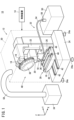
- FIG. 1 is a schematic diagram of a machine tool according to an embodiment.
- FIG. 2 is a block diagram of the control device.
- FIG. 3 is a flowchart showing the control method according to the embodiment.
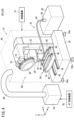
- FIG. 4 is a schematic diagram of a machine tool according to Modification 1.
- FIG. 5 is a block diagram of a control device according to a second modification.
- FIG. 1 is a schematic diagram of a machine tool 10 according to an embodiment.
- the X direction and Y direction shown in FIG. 1 are directions parallel to the horizontal plane.
- the X direction and the Y direction are orthogonal to each other.
- the Z direction shown in FIG. 1 is a direction parallel to the direction of gravity. Therefore, the Z direction is orthogonal to the X direction and the Y direction.
- the Z direction shown in FIG. 1 indicates a direction opposite to the direction of gravity.
- the machine tool 10 includes a processing machine 12 and a control device 14.
- the processing machine 12 is a machine that processes a workpiece using a tool 16.
- the processing machine 12 includes a spindle 18, a spindle head 20, a column 22, a pedestal 24, a table 26, a table drive section 28, a cover 30, a coolant supply device 32, and a mist collector 34.
- a tool holder 36 is attached to the main shaft 18 (see FIG. 1).
- the tool holder 36 can be attached to and detached from the main shaft 18.
- Tool holder 36 holds tool 16.
- the tool 16 is, for example, a hail bit, a drill, an end mill, a milling cutter, or the like.
- the processing machine 12 further includes a tool magazine 38.
- the tool magazine 38 removably holds a plurality of tools 16.
- One tool 16 among the plurality of tools 16 held in the tool magazine 38 is replaceably attached to the tool holder 36.
- the spindle head 20 supports the spindle 18. Further, the spindle head 20 includes a motor that rotates the spindle 18. The tool 16 mounted on the spindle 18 via the tool holder 36 rotates together with the spindle 18.
- the column 22 supports the spindle head 20. Further, the column 22 includes a motor that moves the spindle head 20 in the Z direction. Column 22 is supported by pedestal 24.
- the pedestal 24 is installed on the installation surface.
- the installation surface is, for example, a factory floor.
- the installation surface may be a support surface of a stand provided on the floor.
- the installation surface extends parallel to the horizontal plane, for example.
- the pedestal 24 may include a plurality of legs 24a. Each leg 24a is, for example, a caster, a jack, or the like.
- the table drive unit 28 is supported by the pedestal 24.
- the table drive section 28 includes a first slide section 42, a saddle 44, and a second slide section 46.
- the first slide part 42 is installed on the pedestal 24.
- the first slide portion 42 includes, for example, a guide rail extending in the Y direction.
- the first slide portion 42 supports a saddle 44 .
- the saddle 44 moves in the Y direction in response to being driven by a motor (not shown).
- the motor is controlled by a control device 14.
- the saddle 44 moves while being guided by the first slide part 42. A more detailed explanation of the control device 14 will be given later.
- the second slide part 46 is provided on the saddle 44.
- the second slide portion 46 includes, for example, a guide rail extending in the X direction.
- the table 26 supports a workpiece (not shown) below the main shaft 18.
- the table 26 is supported by the second slide section 46.
- the table 26 moves in the X direction in response to being driven by a motor (not shown).
- the motor is controlled by a control device 14.
- the table 26 moves while being guided by the second slide section 46.
- the cover 30 covers the spindle 18, the spindle head 20, the column 22, the pedestal 24, the table 26, and the table drive section 28. Thereby, the cover 30 forms a processing area 48. The workpiece is processed within the processing area 48 .
- the cover 30 further includes a door (not shown) and a window (not shown).
- the operator can carry in workpieces into the processing area 48 through the open door. Further, the operator can easily check the condition inside the processing area 48 through the window.
- the coolant supply device 32 is a device that supplies coolant to the processing area 48.
- the coolant supply device 32 includes a coolant tank 50, a nozzle 52, a supply pipe 54, and a pump 56.
- the coolant tank 50 stores coolant.
- the coolant tank 50 is installed outside the processing area 48.
- the nozzle 52 is a discharge part that discharges coolant. Nozzle 52 is arranged within processing area 48 . Note that the coolant supply device 32 may include a plurality of nozzles 52.
- the supply pipe 54 is a pipe that connects the coolant tank 50 and the nozzle 52.
- the coolant supply device 32 may include a plurality of supply pipes 54.
- the number of supply pipes 54 is determined depending on the number of nozzles 52, for example.
- the supply pipe 54 passes through the cover 30 and connects the coolant tank 50 and the nozzle 52.
- the pump 56 is connected to the supply pipe 54.
- the pump 56 pumps up the coolant in the coolant tank 50 and sends it to the nozzle 52. As a result, coolant is discharged from the nozzle 52 into the processing area 48 . Note that the pump 56 is controlled by the control device 14.
- the coolant discharged into the machining area 48 cools the tool 16 and the workpiece.
- coolant mist is generated.
- the mist may leak out of the processing area 48 through the small gaps created in the processing machine 12.
- the mist collector 34 is a device that collects mist within the processing area 48.
- the mist collector 34 is installed outside the processing area 48. Further, the mist collector 34 is connected to the cover 30 via a duct 58.
- the mist collector 34 collects mist by sucking air within the processing area 48. This prevents mist from leaking out of the processing area 48.
- mist collector 34 may collect not only mist but also dust by suctioning the air within the processing area 48. This also prevents dust from leaking out of the processing area 48.
- the mist collector 34 may be connected to the coolant tank 50. Thereby, the mist collected by the mist collector 34 can be returned to the coolant tank 50 as coolant.
- mist collector 34 and the coolant tank 50 When connecting the mist collector 34 and the coolant tank 50, it is preferable that the mist collector 34 and the coolant tank 50 are connected via a filter (not shown).
- the filtration device removes impurities from the coolant sent from the mist collector 34 to the coolant tank 50.
- clean coolant By connecting the mist collector 34 and the coolant tank 50 via a filtration device, clean coolant can be returned from the mist collector 34 to the coolant tank 50.
- Impurities in the coolant are, for example, chips collected together with the mist.
- FIG. 2 is a block diagram of the control device 14.
- the control device 14 is a computer that controls the processing machine 12.
- the control device 14 is, for example, a numerical control device.
- the control device 14 includes a display section 60, an operation section 62, a storage section 64, a calculation section 66, and a backup power supply section 68.
- the display unit 60 is a display device including a display screen 60d.
- the display unit 60 is, for example, a liquid crystal display device or an OEL (Organic Electro-Luminescence) display device.
- the operation unit 62 is an input device that accepts instructions from an operator to the control device 14.
- the operation unit 62 includes, for example, an operation panel 62a, a touch panel 62b, and the like.
- the touch panel 62b is provided on the display screen 60d.
- the operation unit 62 (operation panel 62a) may include a keyboard, a mouse, and the like.
- the storage unit 64 may include a volatile memory (not shown) and a nonvolatile memory (not shown). Examples of volatile memory include RAM (Random Access Memory). Examples of the nonvolatile memory include ROM (Read Only Memory), flash memory, and the like. Data, etc. may be stored in volatile memory, for example. Programs, data tables, maps, etc. may be stored in non-volatile memory, for example. At least a portion of the storage unit 64 may be included in a processor, an integrated circuit, or the like as described above. The storage unit 64 stores a control program 70 and a machining program 72.
- the control program 70 is a program for causing the control device 14 to execute the control method according to the present embodiment. A more detailed explanation of the control method will be given later.
- the machining program 72 is a program that includes control instructions for the machining machine 12.
- the machining program 72 includes, for example, a plurality of control instructions for controlling each of the above-mentioned motors. Further, the machining program 72 includes, for example, a plurality of control instructions for controlling the coolant supply device 32.
- the machining program 72 is created or edited in advance by an operator.
- the calculation unit 66 may be configured by a processor such as a CPU (Central Processing Unit) or a GPU (Graphics Processing Unit). That is, the calculation unit 66 may be configured by a processing circuit.
- a processor such as a CPU (Central Processing Unit) or a GPU (Graphics Processing Unit). That is, the calculation unit 66 may be configured by a processing circuit.
- the calculation section 66 includes a processing control section 74 and a collector control section 76.
- the processing control section 74 and the collector control section 76 are realized by the calculation section 66 executing the control program 70.
- the processing control section 74 and the collector control section 76 may be realized by an integrated circuit such as an ASIC (Application Specific Integrated Circuit) or an FPGA (Field-Programmable Gate Array).
- the processing control section 74 and the collector control section 76 may be configured by an electronic circuit including a discrete device.
- the processing control unit 74 processes the workpiece by controlling the processing machine 12 based on the processing program 72.
- the machining control unit 74 controls the rotation of the spindle 18, the movement of the spindle head 20, and the movement of the table 26 based on the machining program 72.
- the mist collector 34 is controlled by the collector control section 76.
- the processing control unit 74 determines whether coolant is used in the processing performed by the processing machine 12 before cutting of the workpiece is started. This determination is made based on the machining program 72 or the operator's instructions.
- the machining program 72 includes a control command to start the coolant supply device 32.
- the processing control unit 74 determines that coolant is used in the processing performed by the processing machine 12. Further, for example, even if the machining program 72 does not include a control command to start the coolant supply device 32, the operator may instruct the control device 14 to start the coolant supply device 32. In this case, the processing control unit 74 determines that coolant is used in the processing performed by the processing machine 12.
- the machining control unit 74 determines whether machining based on the machining program 72 has been completed after the start of machining. For example, when all control commands necessary for processing the workpiece have been executed, the processing control unit 74 determines that the processing based on the processing program 72 has been completed.
- the collector control unit 76 determines whether or not to automatically start the mist collector 34 based on the determination result of whether coolant is used in the processing performed by the processing machine 12.
- the collector control unit 76 does not automatically start the mist collector 34. This prevents the mist collector 34 from operating unnecessarily when no mist is generated. Therefore, the power consumption of the mist collector 34 is suppressed.
- the collector control unit 76 controls the mist collector 34 to automatically start the mist collector 34.
- mist generated within the processing area 48 during processing can be collected by the mist collector 34.
- the mist collector 34 is automatically activated. Therefore, mist is prevented from leaking out of the processing area 48 due to human error.
- the collector control unit 76 preferably does not start the mist collector 34 until the processing is started. In other words, the collector control unit 76 preferably activates the mist collector 34 in response to the start of processing. This prevents the mist collector 34 from consuming power before mist is generated. In this case, the collector control unit 76 automatically starts the mist collector 34 when the operator instructs the control device 14 to start processing, for example. The collector control unit 76 may automatically start the mist collector 34 when the operator instructs the control device 14 to start the coolant supply device 32 .
- the collector control unit 76 determines whether or not to automatically stop the mist collector 34 based on the result of the determination as to whether or not the machining based on the machining program 72 has been completed. When the mist collector 34 is activated and the machining based on the machining program 72 is completed, the collector control unit 76 automatically stops the mist collector 34. This prevents the mist collector 34 from operating excessively after finishing machining due to, for example, human error.
- the collector control unit 76 stops the mist collector 34 after a predetermined time TM has elapsed since the end of processing. By intentionally continuing to operate the mist collector 34 even after the processing is completed, it is possible to prevent mist from being omitted from collection. Since the mist collector 34 is automatically stopped when the predetermined time TM has elapsed from the end of processing, the power consumption of the mist collector 34 is suppressed from becoming excessively large.
- the starting timing of the predetermined time TM is the time when the machining control unit 74 determines that the machining based on the machining program 72 has been completed. However, the collector control unit 76 may calculate (estimate) the end timing of the machining based on the machining program 72 based on the machining program 72. In that case, the collector control unit 76 may use the calculated end timing as the starting timing of the predetermined time TM.
- Information indicating the predetermined time TM is set in the control device 14 by an operator, for example. However, the information indicating the predetermined time TM may be set in the control device 14 by the manufacturer of the control device 14.
- the backup power supply section 68 is a power source different from the main power source of the control device 14.
- the backup power supply section 68 includes, for example, a battery.
- the backup power supply section 68 is built into the control device 14 .
- the backup power supply unit 68 may be provided in the machine tool 10 as an external power supply for the control device 14. Note that illustration of the main power source of the control device 14 is omitted.
- the backup power supply section 68 supplies power to each section of the control device 14.
- the collector control unit 76 can continue controlling the mist collector 34 even after the main power is turned off. Therefore, for example, the collector control unit 76 can automatically stop the mist collector 34 even after the main power is turned off.
- FIG. 3 is a flowchart illustrating the control method according to the embodiment.
- the control device 14 executes the control method illustrated in FIG. 3, for example.
- the control device 14 executes the control method shown in FIG. 3, for example, when machining is started. Note that at the start of the control method, the mist collector 34 is stopped.
- the control method in FIG. 3 includes a coolant use determination step S1, a start control step S2, a processing control step S3, an end determination step S4, a collector state determination step S5, and a stop control step S6.
- the processing control unit 74 determines whether coolant is used in the processing performed by the processing machine 12. As described above, the processing control unit 74 determines whether or not coolant is used in the processing performed by the processing machine 12 based on the processing program 72 or the operator's instructions.
- a startup control step S2 is started.
- the collector control unit 76 controls the mist collector 34 to automatically activate the mist collector 34.
- the processing control section 74 controls the processing machine 12 to process the workpiece.
- the processing control unit 74 controls the processing machine 12 based on the processing program 72.
- mist is generated within the processing area 48. However, since the mist is collected by the mist collector 34, it does not leak out of the processing area 48.
- the machining control unit 74 determines whether machining based on the machining program 72 has been completed. When the machining is completed (S4: YES), a collector state determination step S5 is started. If the machining is not completed (S4: NO), the machining control step S3 is continued.
- the collector control unit 76 determines whether the mist collector 34 is operating. If the mist collector 34 is operating (S5: YES), a stop control step S6 is started.
- the collector control unit 76 stops the mist collector 34.
- the collector control unit 76 may stop the mist collector 34 immediately, but it is preferable to stop the mist collector 34 after a predetermined time TM has elapsed since the end of processing.
- the control method of FIG. 3 ends when the stop control step S6 ends. Note that if the mist collector 34 is not operating (S5: NO), the stop control step S6 is skipped. In that case, the control method of FIG. 3 ends when the collector state determination step S5 ends.
- FIG. 4 is a schematic diagram of a machine tool 101 (10) according to modification example 1.
- the machine tool 101 further includes a sub-control device 78.
- the sub-control device 78 is a computer separate from the control device 14.
- the sub-control device 78 includes, for example, a processor and a memory.
- Sub-controller 78 may include integrated circuits, discrete devices, and the like.
- the sub-control device 78 controls the mist collector 34 in place of the collector control unit 76 when the control device 14 stops. Therefore, even if the control device 14 stops, the mist collector 34 is controlled by the sub-control device 78 in the same manner as in the embodiment.
- the mist collector 34 collects the mist until the predetermined time TM has elapsed after the processing is completed. In such a case, the sub-control device 78 can control the mist collector 34 instead of the control device 14.
- the sub-control device 78 and the control device 14 communicate as appropriate and share data necessary for controlling the mist collector 34.
- the sub-control device 78 and the control device 14 share various information regarding the necessity of coolant during machining, the progress of machining, the elapsed time after machining is completed, and the like. Thereby, the sub-control device 78 can smoothly take over the control that was being performed by the collector control section 76. According to this modification, even after the control device 14 is stopped, the control of the mist collector 34 can be continued by the sub-control device 78.
- FIG. 5 is a block diagram of a control device 142 (14) according to the second modification.
- the control device 142 further includes an alarm output section 80.
- the alarm output unit 80 outputs an alarm when an abnormality occurs in the machine tool 10.
- the machine tool 10 is appropriately equipped with sensors (not shown) for detecting failures in various parts such as the spindle 18, the spindle head 20, and the table drive section 28.
- the alarm output unit 80 determines whether a failure has occurred in the machine tool 10 based on the signal output by the sensor. When a failure in each part of the machine tool 10 is detected, the alarm output section 80 notifies the operator of the occurrence of the failure, for example, via the display section 60.
- the machining control unit 74 does not start machining until the cause of the alarm is resolved. Furthermore, if the alarm output unit 80 outputs an alarm after the start of machining, the machining control unit 74 suspends the machining based on the machining program 72 until the cause of the alarm is resolved.
- the collector control unit 76 prohibits the operation of the mist collector 34 until the cause of the alarm is eliminated. If the mist collector 34 is in operation at the time the alarm is output, the collector control unit 76 stops the mist collector 34 regardless of the machining program 72 and the operator's instructions.
- the mist collector 34 is prevented from operating when an abnormality occurs in the machine tool 10.
- the collector control unit 76 may decide whether to start the mist collector 34 after starting processing. In that case, the collector control unit 76 acquires information indicating the ejection time during processing.
- the discharge time is the time during which the coolant is discharged into the machining area 48 during machining.
- Information indicating the ejection time is acquired using, for example, a timer.
- the collector control unit 76 may acquire information indicating the discharge amount.
- the discharge amount is the amount of coolant discharged into the machining area 48 during machining. Information indicating the discharge amount is obtained using, for example, a flow rate sensor.
- the collector control unit 76 determines whether or not to start the mist collector 34 based on the ejection time or the ejection amount. For example, when the discharge time or discharge amount is a small value, even if coolant is discharged into the processing area 48, little mist is generated. Therefore, when the ejection time or the ejection amount is a small value, there is little risk that the mist will leak out of the processing area 48. On the other hand, after the ejection time or the ejection amount reaches a certain large value, the risk of mist leaking out of the processing area 48 increases.
- the collector control unit 76 prohibits the operation of the mist collector 34 when the ejection time or the ejection amount is less than or equal to a predetermined threshold. This prevents the mist collector 34 from consuming power unnecessarily. Further, the collector control unit 76 controls the mist collector 34 to automatically start the mist collector 34 when the ejection time or the ejection amount exceeds a predetermined threshold. This prevents mist from leaking out of the processing area 48.
- the threshold value is specified in advance by the operator or the manufacturer of the machine tool 10.
- the collector control unit 76 may change the length of the predetermined time TM according to the ejection time or the ejection amount. For example, the larger the ejection time or the ejection amount, the more mist is generated. Based on this, the collector control unit 76 may lengthen the predetermined time TM as the discharge time or discharge amount increases. This makes it possible to more reliably reduce mist collection failure. On the other hand, the collector control unit 76 may shorten the predetermined time TM as the ejection time or ejection amount becomes smaller. Thereby, the power consumption of the mist collector 34 can be suppressed. The collector control unit 76 may determine the length of the predetermined time TM using a data table in which a plurality of predetermined times TM are stored according to the ejection time or the ejection amount.
- the collector control unit 76 may calculate (predict) the timing at which the ejection time or ejection amount reaches the threshold value based on the processing program 72. Further, the collector control unit 76 may calculate the above-mentioned arrival timing using not only the machining program 72 but also various parameters set in the control device 14 regarding machining. The collector control unit 76 may use the calculated arrival timing as the activation timing of the mist collector 34.
- the coolant discharge method is not limited to the embodiment.
- the coolant may be discharged using a center-through method.
- the coolant supply device 32 supplies coolant to the main shaft 18 .
- the coolant may be flowed along the inner wall of the cover 30 (processing area 48).
- the processing machine 12 may further include a recovery member (not shown) for recovering coolant that falls below the table 26.
- the collection member is, for example, an oil pan provided on the pedestal 24. Some of the coolant supplied to the processing area 48 does not become mist and falls below the table 26. According to this modification, coolant that has fallen below the table 26 can be recovered.
- the collected coolant may be returned to the coolant tank 50. Thereby, the coolant supply device 32 can reuse the collected coolant.
- a filtration device filter
- clean coolant can be returned to the coolant tank 50.
- the processing program 72 may include a control command to start the mist collector 34. In that case, the collector control unit 76 activates the mist collector 34 based on a control command to activate the mist collector 34 . Further, the processing program 72 may include a control command to stop the mist collector 34. In that case, the collector control unit 76 stops the mist collector 34 based on a control command to stop the mist collector 34.
- the first invention includes a coolant supply device (32) that supplies coolant to a processing area (48), and a mist collector (34) that collects mist in the processing area, and a A control device (14) for a machine tool (10) that processes a machine tool (10), which controls the machine tool to perform the process based on a process program (72) and determines whether the process has been completed.
- the control device includes a processing control section (74) and a collector control section (76) that automatically stops the mist collector when the processing is finished.
- the collector control section may automatically start the mist collector to collect the mist. This prevents mist from leaking outside the processing area.
- the collector control section may stop the mist collector after a predetermined time (TM) has elapsed from the end of the processing.
- TM predetermined time
- the processing control unit determines whether or not the coolant is used in the processing based on the processing program or an operator's instruction, and the collector control unit determines whether or not the coolant is used in the processing, and the collector control unit
- the mist collector may be controlled based on the determination result. As a result, the mist collector is automatically controlled.
- the above control device further includes an alarm output section (80) that outputs an alarm when an abnormality occurs in the machine tool, and when the alarm output section outputs the alarm, the collector control section:
- the operation of the mist collector may be prohibited. This prevents the mist collector from operating if an abnormality occurs in the machine tool.
- a second invention is a machine tool (10) having the control device according to the first invention.
- the machine tool described above may further include a sub-control device (78) that controls the mist collector in place of the collector control section when the control device stops. Thereby, even if the control device is stopped, automatic control of the mist collector is performed.
- a sub-control device (78) that controls the mist collector in place of the collector control section when the control device stops.
- a third invention includes a coolant supply device (32) that supplies coolant to a processing area (48), and a mist collector (34) that collects mist in the processing area, and a A control method in which a computer (14) controls a machine tool (10) that processes a machine tool, the computer comprising: a completion determination step (S4) in which the computer determines whether or not the machining based on the machining program (72) has been completed; and a stop control step (S6) in which the computer controls the mist collector to automatically stop the mist collector when the processing is completed.
Abstract
A control device (14) for a machine tool (10), which machines a workpiece in a processing area (48) and is equipped with a coolant supplier (32) that supplies coolant to the processing area (48) and a mist collector (34) that collects mist within the processing area (48), comprises a machining control unit (74) that controls the machine tool (10) to perform machining on the basis of a machining program (72) and determines whether the machining has finished, and a collector control unit (76) that automatically stops the mist collector (34) if the machining has finished.
Description
本発明は、制御装置、工作機械および制御方法に関する。
The present invention relates to a control device, a machine tool, and a control method.
ミストコレクタは、工作機械の加工エリア内に発生するミストを回収する(特開2012-76006号公報も参照)。ミストコレクタは、加工エリア内のミストを回収することで、加工エリア外にミストが漏出することを防止する。ミストは、気中に浮遊する微粒子状のクーラントである。
The mist collector collects mist generated within the processing area of the machine tool (see also Japanese Patent Application Laid-Open No. 2012-76006). The mist collector prevents mist from leaking outside the processing area by collecting the mist within the processing area. Mist is particulate coolant that floats in the air.
加工エリア外にミストが漏出することを確実に防止するために、ミストコレクタは、長時間にわたって作動されることが多い。しかしながら、ミストコレクタは、長時間にわたって作動することで、多大な電力を消費する。
In order to reliably prevent mist from leaking outside the processing area, the mist collector is often operated for a long time. However, the mist collector consumes a large amount of power by operating for a long time.
本発明は、上述した課題を解決することを目的とする。
The present invention aims to solve the above-mentioned problems.
本発明の第1の態様は、加工エリアにクーラントを供給するクーラント供給器と、前記加工エリア内のミストを回収するミストコレクタとを備え、前記加工エリア内で加工対象物を加工する工作機械の制御装置であって、加工プログラムに基づいて前記工作機械を制御して前記加工を行うと共に、前記加工が終了したか否かを判定する加工制御部と、前記加工が終了した場合に、前記ミストコレクタを自動で停止させるコレクタ制御部と、を備える、制御装置である。
A first aspect of the present invention is a machine tool that processes a workpiece in the processing area, and includes a coolant supply device that supplies coolant to a processing area, and a mist collector that collects mist in the processing area. The control device includes a processing control section that controls the machine tool to perform the processing based on a processing program and determines whether or not the processing has been completed, and a processing control unit that controls the mist when the processing is completed. The present invention is a control device including a collector control unit that automatically stops a collector.
本発明の第2の態様は、上記第1の態様に係る制御装置を有する、工作機械である。
A second aspect of the present invention is a machine tool having the control device according to the first aspect.
本発明の第3の態様は、加工エリアにクーラントを供給するクーラント供給器と、前記加工エリア内のミストを回収するミストコレクタとを備え、前記加工エリア内で加工対象物を加工する工作機械をコンピュータが制御する制御方法であって、加工プログラムに基づく前記加工が終了したか否かを前記コンピュータが判定する終了判定ステップと、前記加工が終了した場合に、前記ミストコレクタを前記コンピュータが制御して、自動で停止させる停止制御ステップと、を含む、制御方法である。
A third aspect of the present invention provides a machine tool that processes a workpiece in the processing area, and includes a coolant supply device that supplies coolant to a processing area, and a mist collector that collects mist in the processing area. A control method controlled by a computer, comprising a completion determination step in which the computer determines whether or not the machining based on the machining program has been completed, and a step in which the computer controls the mist collector when the machining is completed. This control method includes a stop control step of automatically stopping the vehicle.
本発明によれば、ミストコレクタの消費電力を抑制することができる。
According to the present invention, the power consumption of the mist collector can be suppressed.
[実施形態]
図1は、実施形態に係る工作機械10の模式図である。 [Embodiment]
FIG. 1 is a schematic diagram of amachine tool 10 according to an embodiment.
図1は、実施形態に係る工作機械10の模式図である。 [Embodiment]
FIG. 1 is a schematic diagram of a
なお、図1に示されるX方向とY方向とは、水平面に平行な方向である。X方向とY方向とは、互いに直交する。図1に示されるZ方向は、重力方向に平行な方向である。したがって、Z方向は、X方向とY方向とに直交する。ただし、図1に示されるZ方向は、重力方向の反対方向を示す。
Note that the X direction and Y direction shown in FIG. 1 are directions parallel to the horizontal plane. The X direction and the Y direction are orthogonal to each other. The Z direction shown in FIG. 1 is a direction parallel to the direction of gravity. Therefore, the Z direction is orthogonal to the X direction and the Y direction. However, the Z direction shown in FIG. 1 indicates a direction opposite to the direction of gravity.
工作機械10は、加工機12と、制御装置14とを備える。
The machine tool 10 includes a processing machine 12 and a control device 14.
加工機12は、工具16を用いて加工対象物を加工する機械である。加工機12は、主軸18と、主軸頭20と、コラム22と、台座24と、テーブル26と、テーブル駆動部28と、カバー30と、クーラント供給器32と、ミストコレクタ34とを備える。
The processing machine 12 is a machine that processes a workpiece using a tool 16. The processing machine 12 includes a spindle 18, a spindle head 20, a column 22, a pedestal 24, a table 26, a table drive section 28, a cover 30, a coolant supply device 32, and a mist collector 34.
主軸18には、工具ホルダ36が取り付けられる(図1参照)。工具ホルダ36は主軸18に着脱可能である。工具ホルダ36は、工具16を保持する。工具16は、例えば、ヘールバイト、ドリル、エンドミル、フライス等である。
A tool holder 36 is attached to the main shaft 18 (see FIG. 1). The tool holder 36 can be attached to and detached from the main shaft 18. Tool holder 36 holds tool 16. The tool 16 is, for example, a hail bit, a drill, an end mill, a milling cutter, or the like.
加工機12は、ツールマガジン38をさらに備える。ツールマガジン38は、複数の工具16を着脱可能に保持する。ツールマガジン38に保持された複数の工具16のうち1つの工具16が、工具ホルダ36に交換可能に装着される。
The processing machine 12 further includes a tool magazine 38. The tool magazine 38 removably holds a plurality of tools 16. One tool 16 among the plurality of tools 16 held in the tool magazine 38 is replaceably attached to the tool holder 36.
主軸頭20は、主軸18を支持する。また、主軸頭20は、主軸18を回転させるモータを含む。工具ホルダ36を介して主軸18に装着された工具16は、主軸18と一緒に回転する。
The spindle head 20 supports the spindle 18. Further, the spindle head 20 includes a motor that rotates the spindle 18. The tool 16 mounted on the spindle 18 via the tool holder 36 rotates together with the spindle 18.
コラム22は、主軸頭20を支持する。また、コラム22は、主軸頭20をZ方向に移動させるモータを含む。コラム22は、台座24に支持される。
The column 22 supports the spindle head 20. Further, the column 22 includes a motor that moves the spindle head 20 in the Z direction. Column 22 is supported by pedestal 24.
台座24は、設置面上に設置される。設置面は、例えば工場の床である。設置面は、床上に備えられた台の支持面でもよい。設置面は、例えば、水平面に平行に延在する。台座24は、複数の脚部24aを備えてもよい。各脚部24aは、例えば、キャスタ、ジャッキ等である。
The pedestal 24 is installed on the installation surface. The installation surface is, for example, a factory floor. The installation surface may be a support surface of a stand provided on the floor. The installation surface extends parallel to the horizontal plane, for example. The pedestal 24 may include a plurality of legs 24a. Each leg 24a is, for example, a caster, a jack, or the like.
テーブル駆動部28は、台座24に支持される。テーブル駆動部28は、第1スライド部42と、サドル44と、第2スライド部46とを備える。
The table drive unit 28 is supported by the pedestal 24. The table drive section 28 includes a first slide section 42, a saddle 44, and a second slide section 46.
第1スライド部42は、台座24上に設置される。第1スライド部42は、例えば、Y方向に延在するガイドレールを含む。第1スライド部42は、サドル44を支持する。
The first slide part 42 is installed on the pedestal 24. The first slide portion 42 includes, for example, a guide rail extending in the Y direction. The first slide portion 42 supports a saddle 44 .
サドル44は、不図示のモータが駆動することに応じて、Y方向に移動する。当該モータは、制御装置14に制御される。サドル44は、第1スライド部42に案内されつつ移動する。制御装置14のより詳しい説明は、後述する。
The saddle 44 moves in the Y direction in response to being driven by a motor (not shown). The motor is controlled by a control device 14. The saddle 44 moves while being guided by the first slide part 42. A more detailed explanation of the control device 14 will be given later.
第2スライド部46は、サドル44上に備えられる。第2スライド部46は、例えば、X方向に延在するガイドレールを含む。
The second slide part 46 is provided on the saddle 44. The second slide portion 46 includes, for example, a guide rail extending in the X direction.
テーブル26は、主軸18の下方において、不図示の加工対象物を支持する。テーブル26は、第2スライド部46に支持される。テーブル26は、不図示のモータが駆動することに応じて、X方向に移動する。当該モータは、制御装置14に制御される。テーブル26は、第2スライド部46に案内されつつ移動する。
The table 26 supports a workpiece (not shown) below the main shaft 18. The table 26 is supported by the second slide section 46. The table 26 moves in the X direction in response to being driven by a motor (not shown). The motor is controlled by a control device 14. The table 26 moves while being guided by the second slide section 46.
カバー30は、主軸18と、主軸頭20と、コラム22と、台座24と、テーブル26と、テーブル駆動部28とを覆う。これにより、カバー30は、加工エリア48を形成する。加工対象物は、加工エリア48内において加工される。
The cover 30 covers the spindle 18, the spindle head 20, the column 22, the pedestal 24, the table 26, and the table drive section 28. Thereby, the cover 30 forms a processing area 48. The workpiece is processed within the processing area 48 .
カバー30は、不図示の扉と、不図示の窓とをさらに備える。オペレータは、開状態の扉を介して、加工エリア48内への加工対象物の搬入作業等を行うことができる。また、オペレータは、窓を介して、加工エリア48内の状態を容易に確認することができる。
The cover 30 further includes a door (not shown) and a window (not shown). The operator can carry in workpieces into the processing area 48 through the open door. Further, the operator can easily check the condition inside the processing area 48 through the window.
クーラント供給器32は、加工エリア48にクーラントを供給する装置である。クーラント供給器32は、クーラントタンク50と、ノズル52と、供給管54と、ポンプ56とを備える。
The coolant supply device 32 is a device that supplies coolant to the processing area 48. The coolant supply device 32 includes a coolant tank 50, a nozzle 52, a supply pipe 54, and a pump 56.
クーラントタンク50は、クーラントを貯留する。クーラントタンク50は、加工エリア48の外に設置される。
The coolant tank 50 stores coolant. The coolant tank 50 is installed outside the processing area 48.
ノズル52は、クーラントを吐出する吐出部である。ノズル52は、加工エリア48内に配される。なお、クーラント供給器32は、複数のノズル52を備えてもよい。
The nozzle 52 is a discharge part that discharges coolant. Nozzle 52 is arranged within processing area 48 . Note that the coolant supply device 32 may include a plurality of nozzles 52.
供給管54は、クーラントタンク50とノズル52とを接続する管である。クーラント供給器32は、複数の供給管54を備えてもよい。供給管54の数は、例えばノズル52の数に応じて決められる。供給管54は、カバー30を貫通して、クーラントタンク50とノズル52とを接続する。
The supply pipe 54 is a pipe that connects the coolant tank 50 and the nozzle 52. The coolant supply device 32 may include a plurality of supply pipes 54. The number of supply pipes 54 is determined depending on the number of nozzles 52, for example. The supply pipe 54 passes through the cover 30 and connects the coolant tank 50 and the nozzle 52.
ポンプ56は、供給管54に接続される。ポンプ56は、クーラントタンク50内のクーラントを汲み上げて、ノズル52に送る。これにより、ノズル52から加工エリア48内にクーラントが吐出される。なお、ポンプ56は制御装置14によって制御される。
The pump 56 is connected to the supply pipe 54. The pump 56 pumps up the coolant in the coolant tank 50 and sends it to the nozzle 52. As a result, coolant is discharged from the nozzle 52 into the processing area 48 . Note that the pump 56 is controlled by the control device 14.
加工エリア48に吐出されるクーラントは、工具16と加工対象物とを冷却する。加工エリア48において加工が行われる際に、クーラントのミストが発生する。ミストは、加工機12に生じる小さな隙間を介して、加工エリア48外に漏出するおそれがある。
The coolant discharged into the machining area 48 cools the tool 16 and the workpiece. When machining is performed in the machining area 48, coolant mist is generated. The mist may leak out of the processing area 48 through the small gaps created in the processing machine 12.
ミストコレクタ34は、加工エリア48内のミストを回収する装置である。ミストコレクタ34は、加工エリア48の外に設置される。また、ミストコレクタ34は、ダクト58を介して、カバー30に接続されている。ミストコレクタ34は、加工エリア48内の空気を吸引することで、ミストを回収する。これにより、ミストが加工エリア48外に漏出することが防止される。
The mist collector 34 is a device that collects mist within the processing area 48. The mist collector 34 is installed outside the processing area 48. Further, the mist collector 34 is connected to the cover 30 via a duct 58. The mist collector 34 collects mist by sucking air within the processing area 48. This prevents mist from leaking out of the processing area 48.
工具16が加工対象物を切削することで、加工エリア48内に微細な切屑が粉じんとして発生する。この粉じんは、ミストと同様に、加工機12に生じる小さな隙間を介して、加工エリア48外に漏出するおそれがある。ミストコレクタ34は、加工エリア48内の空気を吸引することで、ミストのみならず粉じんを回収してもよい。これにより、粉じんが加工エリア48外に漏出することも、防止される。
When the tool 16 cuts the workpiece, fine chips are generated as dust within the processing area 48. This dust, like mist, may leak out of the processing area 48 through small gaps created in the processing machine 12. The mist collector 34 may collect not only mist but also dust by suctioning the air within the processing area 48. This also prevents dust from leaking out of the processing area 48.
ミストコレクタ34は、クーラントタンク50に接続されてもよい。これにより、ミストコレクタ34が回収するミストを、クーラントとして、クーラントタンク50に戻すことができる。
The mist collector 34 may be connected to the coolant tank 50. Thereby, the mist collected by the mist collector 34 can be returned to the coolant tank 50 as coolant.
ミストコレクタ34とクーラントタンク50とを接続する場合には、ミストコレクタ34と、クーラントタンク50とは、不図示の濾過装置(フィルタ)を介して接続されることが好ましい。濾過装置は、ミストコレクタ34からクーラントタンク50に送られるクーラント中の不純物を除去する。濾過装置を介してミストコレクタ34とクーラントタンク50とを接続すれば、ミストコレクタ34からクーラントタンク50に清潔なクーラントを戻すことができる。クーラント中の不純物は、例えば、ミストと一緒に回収された切屑である。
When connecting the mist collector 34 and the coolant tank 50, it is preferable that the mist collector 34 and the coolant tank 50 are connected via a filter (not shown). The filtration device removes impurities from the coolant sent from the mist collector 34 to the coolant tank 50. By connecting the mist collector 34 and the coolant tank 50 via a filtration device, clean coolant can be returned from the mist collector 34 to the coolant tank 50. Impurities in the coolant are, for example, chips collected together with the mist.
図2は、制御装置14のブロック図である。
FIG. 2 is a block diagram of the control device 14.
制御装置14は、加工機12を制御するコンピュータである。制御装置14は、例えば数値制御装置である。制御装置14は、表示部60と、操作部62と、記憶部64と、演算部66と、予備電源部68とを備える。
The control device 14 is a computer that controls the processing machine 12. The control device 14 is, for example, a numerical control device. The control device 14 includes a display section 60, an operation section 62, a storage section 64, a calculation section 66, and a backup power supply section 68.
表示部60は、表示画面60dを備える表示装置である。表示部60は、例えば、液晶表示装置またはOEL(Organic Electro-Luminescence)表示装置である。
The display unit 60 is a display device including a display screen 60d. The display unit 60 is, for example, a liquid crystal display device or an OEL (Organic Electro-Luminescence) display device.
操作部62は、制御装置14に対するオペレータの指示を受け付ける入力装置である。操作部62は、例えば操作盤62a、タッチパネル62b等を含む。タッチパネル62bは、表示画面60dに備えられる。操作部62(操作盤62a)は、キーボード、マウス等を備えてもよい。
The operation unit 62 is an input device that accepts instructions from an operator to the control device 14. The operation unit 62 includes, for example, an operation panel 62a, a touch panel 62b, and the like. The touch panel 62b is provided on the display screen 60d. The operation unit 62 (operation panel 62a) may include a keyboard, a mouse, and the like.
記憶部64は、不図示の揮発性メモリと、不図示の不揮発性メモリとによって構成され得る。揮発性メモリとしては、例えばRAM(Random Access Memory)等が挙げられ得る。不揮発性メモリとしては、例えばROM(Read Only Memory)、フラッシュメモリ等が挙げられ得る。データ等が、例えば揮発性メモリに記憶され得る。プログラム、データテーブル、マップ等が、例えば不揮発性メモリに記憶され得る。記憶部64の少なくとも一部が、上述したようなプロセッサ、集積回路等に備えられていてもよい。記憶部64は、制御プログラム70と、加工プログラム72とを記憶する。
The storage unit 64 may include a volatile memory (not shown) and a nonvolatile memory (not shown). Examples of volatile memory include RAM (Random Access Memory). Examples of the nonvolatile memory include ROM (Read Only Memory), flash memory, and the like. Data, etc. may be stored in volatile memory, for example. Programs, data tables, maps, etc. may be stored in non-volatile memory, for example. At least a portion of the storage unit 64 may be included in a processor, an integrated circuit, or the like as described above. The storage unit 64 stores a control program 70 and a machining program 72.
制御プログラム70は、本実施形態に係る制御方法を制御装置14に実行させるためのプログラムである。制御方法のより詳しい説明は後述する。
The control program 70 is a program for causing the control device 14 to execute the control method according to the present embodiment. A more detailed explanation of the control method will be given later.
加工プログラム72は、加工機12に対する制御命令を含むプログラムである。加工プログラム72は、例えば、上述の各モータを制御するための複数の制御命令を含む。また、加工プログラム72は、例えば、クーラント供給器32を制御するための複数の制御命令を含む。加工プログラム72は、オペレータによって事前に作成または編集される。
The machining program 72 is a program that includes control instructions for the machining machine 12. The machining program 72 includes, for example, a plurality of control instructions for controlling each of the above-mentioned motors. Further, the machining program 72 includes, for example, a plurality of control instructions for controlling the coolant supply device 32. The machining program 72 is created or edited in advance by an operator.
演算部66は、例えば、CPU(Central Processing Unit)、GPU(Graphics Processing Unit)等のプロセッサ(Processor)によって構成され得る。すなわち、演算部66は、処理回路(Processing Circuitry)によって構成され得る。
The calculation unit 66 may be configured by a processor such as a CPU (Central Processing Unit) or a GPU (Graphics Processing Unit). That is, the calculation unit 66 may be configured by a processing circuit.
演算部66は、加工制御部74と、コレクタ制御部76とを備える。加工制御部74と、コレクタ制御部76とは、演算部66が制御プログラム70を実行することで、実現される。なお、加工制御部74と、コレクタ制御部76との少なくとも一部が、ASIC(Application Specific Integrated Circuit)、FPGA(Field-Programmable Gate Array)等の集積回路によって実現されるようにしてもよい。また、加工制御部74と、コレクタ制御部76との少なくとも一部が、ディスクリートデバイスを含む電子回路によって構成されるようにしてもよい。
The calculation section 66 includes a processing control section 74 and a collector control section 76. The processing control section 74 and the collector control section 76 are realized by the calculation section 66 executing the control program 70. Note that at least a portion of the processing control section 74 and the collector control section 76 may be realized by an integrated circuit such as an ASIC (Application Specific Integrated Circuit) or an FPGA (Field-Programmable Gate Array). Further, at least a portion of the processing control section 74 and the collector control section 76 may be configured by an electronic circuit including a discrete device.
加工制御部74は、加工プログラム72に基づいて加工機12を制御することで、加工対象物を加工する。例えば、加工制御部74は、加工プログラム72に基づいて、主軸18の回転、主軸頭20の移動、テーブル26の移動を制御する。ただし、加工機12のうち、ミストコレクタ34の制御は、コレクタ制御部76が行う。
The processing control unit 74 processes the workpiece by controlling the processing machine 12 based on the processing program 72. For example, the machining control unit 74 controls the rotation of the spindle 18, the movement of the spindle head 20, and the movement of the table 26 based on the machining program 72. However, among the processing machines 12, the mist collector 34 is controlled by the collector control section 76.
また、加工制御部74は、加工機12が行う加工においてクーラントが用いられるか否かを、加工対象物の切削が開始される前に判定する。その判定は、加工プログラム72、またはオペレータの指示に基づいて行われる。
Furthermore, the processing control unit 74 determines whether coolant is used in the processing performed by the processing machine 12 before cutting of the workpiece is started. This determination is made based on the machining program 72 or the operator's instructions.
例えば、クーラント供給器32を起動する制御命令が加工プログラム72に含まれる。この場合、加工制御部74は、加工機12が行う加工においてクーラントが用いられると判定する。また、例えば、クーラント供給器32を起動する制御命令が加工プログラム72に含まれない場合であっても、クーラント供給器32の起動をオペレータが制御装置14に指示する場合がある。この場合、加工制御部74は、加工機12が行う加工においてクーラントが用いられると判定する。
For example, the machining program 72 includes a control command to start the coolant supply device 32. In this case, the processing control unit 74 determines that coolant is used in the processing performed by the processing machine 12. Further, for example, even if the machining program 72 does not include a control command to start the coolant supply device 32, the operator may instruct the control device 14 to start the coolant supply device 32. In this case, the processing control unit 74 determines that coolant is used in the processing performed by the processing machine 12.
さらに、加工制御部74は、加工の開始以後において、加工プログラム72に基づく加工が終了したか否かを判定する。例えば、加工対象物を加工するために必要な全ての制御命令を実行し終えた場合に、加工制御部74は、加工プログラム72に基づく加工が終了したと判定する。
Further, the machining control unit 74 determines whether machining based on the machining program 72 has been completed after the start of machining. For example, when all control commands necessary for processing the workpiece have been executed, the processing control unit 74 determines that the processing based on the processing program 72 has been completed.
コレクタ制御部76は、ミストコレクタ34を自動で起動するか否かを、加工機12が行う加工においてクーラントが用いられるか否かの判定結果に基づいて決定する。
The collector control unit 76 determines whether or not to automatically start the mist collector 34 based on the determination result of whether coolant is used in the processing performed by the processing machine 12.
例えば、加工機12が行う加工においてクーラントが用いられない場合、コレクタ制御部76は、ミストコレクタ34を自動で起動させない。これにより、ミストが発生しない場合においてミストコレクタ34が無用に作動することが防止される。そのため、ミストコレクタ34の消費電力が抑制される。
For example, if coolant is not used in the processing performed by the processing machine 12, the collector control unit 76 does not automatically start the mist collector 34. This prevents the mist collector 34 from operating unnecessarily when no mist is generated. Therefore, the power consumption of the mist collector 34 is suppressed.
その一方で、加工機12が行う加工においてクーラントが用いられる場合、コレクタ制御部76は、ミストコレクタ34を制御して、ミストコレクタ34を自動で起動させる。これにより、加工中において加工エリア48内に発生するミストを、ミストコレクタ34によって回収させることができる。しかも、ミストコレクタ34は自動で起動される。したがって、ヒューマンエラーに起因してミストが加工エリア48外に漏出することが防止される。
On the other hand, when coolant is used in the processing performed by the processing machine 12, the collector control unit 76 controls the mist collector 34 to automatically start the mist collector 34. Thereby, mist generated within the processing area 48 during processing can be collected by the mist collector 34. Furthermore, the mist collector 34 is automatically activated. Therefore, mist is prevented from leaking out of the processing area 48 due to human error.
なお、コレクタ制御部76は、加工機12が行う加工においてクーラントが用いられると分かった場合であっても、その加工が開始されるまではミストコレクタ34を起動させないことが好ましい。言い換えると、コレクタ制御部76は、加工が開始されることに応じてミストコレクタ34を起動させることが好ましい。これにより、ミストが発生する前にミストコレクタ34が電力を消費することが防止される。この場合、コレクタ制御部76は、例えば、オペレータから制御装置14に加工の開始が指示された場合に、ミストコレクタ34を自動で起動させる。コレクタ制御部76は、オペレータから制御装置14にクーラント供給器32の起動が指示された場合に、ミストコレクタ34を自動で起動させてもよい。
Note that even if it is determined that coolant will be used in the processing performed by the processing machine 12, the collector control unit 76 preferably does not start the mist collector 34 until the processing is started. In other words, the collector control unit 76 preferably activates the mist collector 34 in response to the start of processing. This prevents the mist collector 34 from consuming power before mist is generated. In this case, the collector control unit 76 automatically starts the mist collector 34 when the operator instructs the control device 14 to start processing, for example. The collector control unit 76 may automatically start the mist collector 34 when the operator instructs the control device 14 to start the coolant supply device 32 .
また、コレクタ制御部76は、ミストコレクタ34を自動で停止するか否かを、加工プログラム72に基づく加工が終了したか否かの判定結果に基づいて決定する。ミストコレクタ34が起動しており、且つ、加工プログラム72に基づく加工が終了した場合、コレクタ制御部76は、ミストコレクタ34を自動で停止させる。これにより、例えばヒューマンエラーに起因して、ミストコレクタ34が加工の終了後において過度に作動することが防止される。
Furthermore, the collector control unit 76 determines whether or not to automatically stop the mist collector 34 based on the result of the determination as to whether or not the machining based on the machining program 72 has been completed. When the mist collector 34 is activated and the machining based on the machining program 72 is completed, the collector control unit 76 automatically stops the mist collector 34. This prevents the mist collector 34 from operating excessively after finishing machining due to, for example, human error.
なお、コレクタ制御部76は、加工の終了から所定時間TMが経過した後にミストコレクタ34を停止させることが好ましい。加工の終了後にもあえてミストコレクタ34を作動させ続けることで、ミストの回収漏れを防止することができる。ミストコレクタ34は加工の終了から所定時間TMが経過した場合に自動で停止されるので、ミストコレクタ34の消費電力が過度に大きくなることが抑制される。
Note that it is preferable that the collector control unit 76 stops the mist collector 34 after a predetermined time TM has elapsed since the end of processing. By intentionally continuing to operate the mist collector 34 even after the processing is completed, it is possible to prevent mist from being omitted from collection. Since the mist collector 34 is automatically stopped when the predetermined time TM has elapsed from the end of processing, the power consumption of the mist collector 34 is suppressed from becoming excessively large.
所定時間TMの起算タイミングは、加工プログラム72に基づく加工が終了したと加工制御部74が判定した時点である。ただし、コレクタ制御部76は、加工プログラム72に基づく加工の終了タイミングを、加工プログラム72に基づいて算出(推定)してもよい。その場合、コレクタ制御部76は、算出した終了タイミングを、所定時間TMの起算タイミングとして用いてもよい。所定時間TMを示す情報は、例えば、オペレータによって制御装置14に設定される。ただし、所定時間TMを示す情報は、制御装置14のメーカによって制御装置14に設定されてもよい。
The starting timing of the predetermined time TM is the time when the machining control unit 74 determines that the machining based on the machining program 72 has been completed. However, the collector control unit 76 may calculate (estimate) the end timing of the machining based on the machining program 72 based on the machining program 72. In that case, the collector control unit 76 may use the calculated end timing as the starting timing of the predetermined time TM. Information indicating the predetermined time TM is set in the control device 14 by an operator, for example. However, the information indicating the predetermined time TM may be set in the control device 14 by the manufacturer of the control device 14.
予備電源部68は、制御装置14の主電源とは別の電源である。予備電源部68は、例えばバッテリを含む。予備電源部68は、制御装置14に内蔵される。ただし、予備電源部68は、制御装置14の外部電源として工作機械10に備えられてもよい。なお、制御装置14の主電源の図示は、省略する。
The backup power supply section 68 is a power source different from the main power source of the control device 14. The backup power supply section 68 includes, for example, a battery. The backup power supply section 68 is built into the control device 14 . However, the backup power supply unit 68 may be provided in the machine tool 10 as an external power supply for the control device 14. Note that illustration of the main power source of the control device 14 is omitted.
ミストコレクタ34の作動中に制御装置14の主電源がオフされた場合において、予備電源部68は、制御装置14の各部に電力を供給する。これにより、コレクタ制御部76は、主電源がオフされた後であっても、ミストコレクタ34の制御を続行することができる。そのため、例えば、コレクタ制御部76は、主電源がオフされた後であっても、ミストコレクタ34を自動で停止させることができる。
When the main power source of the control device 14 is turned off while the mist collector 34 is in operation, the backup power supply section 68 supplies power to each section of the control device 14. Thereby, the collector control unit 76 can continue controlling the mist collector 34 even after the main power is turned off. Therefore, for example, the collector control unit 76 can automatically stop the mist collector 34 even after the main power is turned off.
図3は、実施形態に係る制御方法を例示するフローチャートである。
FIG. 3 is a flowchart illustrating the control method according to the embodiment.
制御装置14は、例えば図3に例示される制御方法を実行する。制御装置14は、例えば加工が開始される場合に、図3の制御方法を実行する。なお、制御方法の開始時点において、ミストコレクタ34は停止している。図3の制御方法は、クーラント使用判定ステップS1と、起動制御ステップS2と、加工制御ステップS3と、終了判定ステップS4と、コレクタ状態判定ステップS5と、停止制御ステップS6とを含む。
The control device 14 executes the control method illustrated in FIG. 3, for example. The control device 14 executes the control method shown in FIG. 3, for example, when machining is started. Note that at the start of the control method, the mist collector 34 is stopped. The control method in FIG. 3 includes a coolant use determination step S1, a start control step S2, a processing control step S3, an end determination step S4, a collector state determination step S5, and a stop control step S6.
クーラント使用判定ステップS1では、加工機12が行う加工においてクーラントが用いられるか否かを、加工制御部74が判定する。上述したように、加工制御部74は、加工機12が行う加工においてクーラントが用いられるか否かを、加工プログラム72またはオペレータの指示に基づいて判定する。
In the coolant use determination step S1, the processing control unit 74 determines whether coolant is used in the processing performed by the processing machine 12. As described above, the processing control unit 74 determines whether or not coolant is used in the processing performed by the processing machine 12 based on the processing program 72 or the operator's instructions.
加工機12が行う加工においてクーラントが用いられる場合(S1:YES)、起動制御ステップS2が開始される。起動制御ステップS2では、コレクタ制御部76がミストコレクタ34を制御して、ミストコレクタ34を自動で起動させる。
If a coolant is used in the processing performed by the processing machine 12 (S1: YES), a startup control step S2 is started. In the activation control step S2, the collector control unit 76 controls the mist collector 34 to automatically activate the mist collector 34.
なお、加工機12が行う加工においてクーラントが用いられない場合(S1:NO)、起動制御ステップS2はスキップされる。
Note that if coolant is not used in the processing performed by the processing machine 12 (S1: NO), the startup control step S2 is skipped.
加工制御ステップS3では、加工制御部74が加工機12を制御して、加工対象物を加工する。加工制御部74は、加工プログラム72に基づいて加工機12を制御する。加工制御ステップS3においてクーラントが用いられる場合、加工エリア48内にミストが発生する。しかし、ミストはミストコレクタ34に回収されるので、加工エリア48外に漏出しない。
In the processing control step S3, the processing control section 74 controls the processing machine 12 to process the workpiece. The processing control unit 74 controls the processing machine 12 based on the processing program 72. When coolant is used in the processing control step S3, mist is generated within the processing area 48. However, since the mist is collected by the mist collector 34, it does not leak out of the processing area 48.
終了判定ステップS4では、加工プログラム72に基づく加工が終了したか否かを、加工制御部74が判定する。加工が終了した場合(S4:YES)、コレクタ状態判定ステップS5が開始される。加工が終了していない場合(S4:NO)、加工制御ステップS3が継続される。
In the end determination step S4, the machining control unit 74 determines whether machining based on the machining program 72 has been completed. When the machining is completed (S4: YES), a collector state determination step S5 is started. If the machining is not completed (S4: NO), the machining control step S3 is continued.
コレクタ状態判定ステップS5では、ミストコレクタ34が作動しているか否かを、コレクタ制御部76が判定する。ミストコレクタ34が作動している場合(S5:YES)、停止制御ステップS6が開始される。
In the collector state determination step S5, the collector control unit 76 determines whether the mist collector 34 is operating. If the mist collector 34 is operating (S5: YES), a stop control step S6 is started.
停止制御ステップS6では、コレクタ制御部76がミストコレクタ34を停止させる。停止制御ステップS6において、コレクタ制御部76は、ミストコレクタ34を直ちに停止させてもよいが、加工が終了してから所定時間TM経過した後にミストコレクタ34を停止させることが好ましい。
In the stop control step S6, the collector control unit 76 stops the mist collector 34. In the stop control step S6, the collector control unit 76 may stop the mist collector 34 immediately, but it is preferable to stop the mist collector 34 after a predetermined time TM has elapsed since the end of processing.
停止制御ステップS6が終了することで、図3の制御方法は終了する。なお、ミストコレクタ34が作動していない場合(S5:NO)、停止制御ステップS6はスキップされる。その場合、コレクタ状態判定ステップS5が終了することで、図3の制御方法は終了する。
The control method of FIG. 3 ends when the stop control step S6 ends. Note that if the mist collector 34 is not operating (S5: NO), the stop control step S6 is skipped. In that case, the control method of FIG. 3 ends when the collector state determination step S5 ends.
[変形例]
以下には、上記実施形態に係る変形例が記載される。ただし、上記実施形態と重複する説明は、以下の説明では適宜省略される。上記実施形態で説明済みの要素には、特に断らない限り、上記実施形態と同一の参照符号が付される。 [Modified example]
Modifications of the above embodiment will be described below. However, descriptions that overlap with the above embodiments will be omitted as appropriate in the following description. Elements already described in the above embodiments are given the same reference numerals as in the above embodiments, unless otherwise specified.
(変形例1)
図4は、変形例1に係る工作機械101(10)の模式図である。 (Modification 1)
FIG. 4 is a schematic diagram of a machine tool 101 (10) according to modification example 1.
図4は、変形例1に係る工作機械101(10)の模式図である。 (Modification 1)
FIG. 4 is a schematic diagram of a machine tool 101 (10) according to modification example 1.
工作機械101は、サブ制御装置78をさらに備える。
The machine tool 101 further includes a sub-control device 78.
サブ制御装置78は、制御装置14とは別のコンピュータである。サブ制御装置78は、例えば、プロセッサとメモリとを備える。サブ制御装置78は、集積回路、ディスクリートデバイス等を備えてもよい。
The sub-control device 78 is a computer separate from the control device 14. The sub-control device 78 includes, for example, a processor and a memory. Sub-controller 78 may include integrated circuits, discrete devices, and the like.
サブ制御装置78は、制御装置14が停止した場合において、コレクタ制御部76に代わってミストコレクタ34を制御する。したがって、ミストコレクタ34は、仮に制御装置14が停止した場合であっても、サブ制御装置78により、実施形態と同様に制御される。
The sub-control device 78 controls the mist collector 34 in place of the collector control unit 76 when the control device 14 stops. Therefore, even if the control device 14 stops, the mist collector 34 is controlled by the sub-control device 78 in the same manner as in the embodiment.
例えば、加工が終了した場合に、オペレータが、直ちに停止することを制御装置14に指示する。これにより、制御装置14は、加工の終了後に直ちに停止する。しかし、上述したように、加工が終了してから所定時間TMが経過するまで、ミストコレクタ34はミストの回収を行うことが好ましい。このような場合において、サブ制御装置78は、制御装置14に代わってミストコレクタ34を制御することができる。
For example, when machining is completed, the operator instructs the control device 14 to stop immediately. As a result, the control device 14 immediately stops after finishing the machining. However, as described above, it is preferable that the mist collector 34 collects the mist until the predetermined time TM has elapsed after the processing is completed. In such a case, the sub-control device 78 can control the mist collector 34 instead of the control device 14.
なお、サブ制御装置78と制御装置14とは、適宜通信して、ミストコレクタ34の制御に必要なデータを共有することが好ましい。例えば、サブ制御装置78と制御装置14とは、加工におけるクーラントの要否、加工の進捗、または、加工が終了してからの経過時間等に関する種々の情報を共有する。これにより、サブ制御装置78は、コレクタ制御部76が行っていた制御を円滑に引き継ぐことができる。本変形例によれば、制御装置14が停止した後においても、ミストコレクタ34の制御をサブ制御装置78により続行することができる。
Note that it is preferable that the sub-control device 78 and the control device 14 communicate as appropriate and share data necessary for controlling the mist collector 34. For example, the sub-control device 78 and the control device 14 share various information regarding the necessity of coolant during machining, the progress of machining, the elapsed time after machining is completed, and the like. Thereby, the sub-control device 78 can smoothly take over the control that was being performed by the collector control section 76. According to this modification, even after the control device 14 is stopped, the control of the mist collector 34 can be continued by the sub-control device 78.
(変形例2)
図5は、変形例2に係る制御装置142(14)のブロック図である。 (Modification 2)
FIG. 5 is a block diagram of a control device 142 (14) according to the second modification.
図5は、変形例2に係る制御装置142(14)のブロック図である。 (Modification 2)
FIG. 5 is a block diagram of a control device 142 (14) according to the second modification.
制御装置142は、アラーム出力部80をさらに備える。
The control device 142 further includes an alarm output section 80.
アラーム出力部80は、工作機械10に異常が発生した場合に、アラームを出力する。例えば、工作機械10に、主軸18、主軸頭20、テーブル駆動部28等の各部位の故障を検出するための不図示のセンサが適宜備えられる。アラーム出力部80は、センサが出力する信号に基づいて、工作機械10に故障が生じたか否かを判定する。工作機械10の各部位の故障が検出された場合、アラーム出力部80は、故障が発生した旨を、例えば表示部60を介してオペレータに報知する。
The alarm output unit 80 outputs an alarm when an abnormality occurs in the machine tool 10. For example, the machine tool 10 is appropriately equipped with sensors (not shown) for detecting failures in various parts such as the spindle 18, the spindle head 20, and the table drive section 28. The alarm output unit 80 determines whether a failure has occurred in the machine tool 10 based on the signal output by the sensor. When a failure in each part of the machine tool 10 is detected, the alarm output section 80 notifies the operator of the occurrence of the failure, for example, via the display section 60.
加工の開始前にアラーム出力部80がアラームを出力した場合、加工制御部74は、アラームの原因が解消されるまで、加工を開始しない。また、加工の開始後にアラーム出力部80がアラームを出力した場合、加工制御部74は、アラームの原因が解消されるまで、加工プログラム72に基づく加工を中断する。
If the alarm output unit 80 outputs an alarm before starting machining, the machining control unit 74 does not start machining until the cause of the alarm is resolved. Furthermore, if the alarm output unit 80 outputs an alarm after the start of machining, the machining control unit 74 suspends the machining based on the machining program 72 until the cause of the alarm is resolved.
アラーム出力部80がアラームを出力した場合、コレクタ制御部76は、アラームの原因が解消されるまで、ミストコレクタ34の作動を禁止する。アラームが出力された時点でミストコレクタ34が作動中であった場合、コレクタ制御部76は、加工プログラム72とオペレータの指示とに拘らず、ミストコレクタ34を停止させる。
When the alarm output unit 80 outputs an alarm, the collector control unit 76 prohibits the operation of the mist collector 34 until the cause of the alarm is eliminated. If the mist collector 34 is in operation at the time the alarm is output, the collector control unit 76 stops the mist collector 34 regardless of the machining program 72 and the operator's instructions.
本変形例によれば、工作機械10に異常が発生した場合においてミストコレクタ34が作動することが防止される。
According to this modification, the mist collector 34 is prevented from operating when an abnormality occurs in the machine tool 10.
(複数の変形例の組み合わせ)
上述された複数の変形例は、矛盾しない範囲内において適宜組み合わされてもよい。 (Combination of multiple variations)
The plurality of modifications described above may be combined as appropriate within the scope of consistency.
上述された複数の変形例は、矛盾しない範囲内において適宜組み合わされてもよい。 (Combination of multiple variations)
The plurality of modifications described above may be combined as appropriate within the scope of consistency.
[変形実施形態]
本発明は、上述した実施形態に限らず、本発明の要旨を逸脱することなく、種々の構成を取り得る。 [Modified embodiment]
The present invention is not limited to the embodiments described above, and can take various configurations without departing from the gist of the present invention.
本発明は、上述した実施形態に限らず、本発明の要旨を逸脱することなく、種々の構成を取り得る。 [Modified embodiment]
The present invention is not limited to the embodiments described above, and can take various configurations without departing from the gist of the present invention.
例えば、上記実施形態では、加工においてクーラントが用いられるか否かに基づいて、ミストコレクタ34を起動するか否かが加工の開始前において決定された。しかし、コレクタ制御部76は、ミストコレクタ34を起動させるか否かを、加工の開始後に決定してもよい。その場合、コレクタ制御部76は、吐出時間を示す情報を、加工中において取得する。吐出時間は、加工中においてクーラントが加工エリア48に吐出された時間である。吐出時間を示す情報は、例えばタイマを用いて取得される。また、コレクタ制御部76は、吐出量を示す情報を取得してもよい。吐出量は、加工中において加工エリア48に吐出されたクーラントの液量である。吐出量を示す情報は、例えば流量センサを用いて取得される。
For example, in the above embodiment, whether or not to start the mist collector 34 is determined before the start of machining based on whether or not coolant is used in machining. However, the collector control unit 76 may decide whether to start the mist collector 34 after starting processing. In that case, the collector control unit 76 acquires information indicating the ejection time during processing. The discharge time is the time during which the coolant is discharged into the machining area 48 during machining. Information indicating the ejection time is acquired using, for example, a timer. Further, the collector control unit 76 may acquire information indicating the discharge amount. The discharge amount is the amount of coolant discharged into the machining area 48 during machining. Information indicating the discharge amount is obtained using, for example, a flow rate sensor.
吐出時間または吐出量を取得する場合、コレクタ制御部76は、ミストコレクタ34を起動させるか否かを、吐出時間または吐出量に基づいて決定する。例えば、吐出時間または吐出量が小さい値である場合、加工エリア48にクーラントが吐出されるとしても、ミストはほとんど発生しない。したがって、吐出時間または吐出量が小さい値である場合、ミストが加工エリア48外に漏出するおそれは小さい。その一方で、吐出時間または吐出量がある程度大きい値に達した後は、ミストが加工エリア48外に漏出するおそれが増大する。以上を踏まえ、コレクタ制御部76は、吐出時間または吐出量が所定の閾値以下である場合、ミストコレクタ34の作動を禁止する。これにより、ミストコレクタ34が無用に電力を消費することが防止される。また、コレクタ制御部76は、吐出時間または吐出量が所定の閾値を超えた場合、ミストコレクタ34を制御して、ミストコレクタ34を自動で起動させる。これにより、ミストが加工エリア48外に漏出することが防止される。閾値は、オペレータまたは工作機械10のメーカによって、予め指定される。
When acquiring the ejection time or the ejection amount, the collector control unit 76 determines whether or not to start the mist collector 34 based on the ejection time or the ejection amount. For example, when the discharge time or discharge amount is a small value, even if coolant is discharged into the processing area 48, little mist is generated. Therefore, when the ejection time or the ejection amount is a small value, there is little risk that the mist will leak out of the processing area 48. On the other hand, after the ejection time or the ejection amount reaches a certain large value, the risk of mist leaking out of the processing area 48 increases. Based on the above, the collector control unit 76 prohibits the operation of the mist collector 34 when the ejection time or the ejection amount is less than or equal to a predetermined threshold. This prevents the mist collector 34 from consuming power unnecessarily. Further, the collector control unit 76 controls the mist collector 34 to automatically start the mist collector 34 when the ejection time or the ejection amount exceeds a predetermined threshold. This prevents mist from leaking out of the processing area 48. The threshold value is specified in advance by the operator or the manufacturer of the machine tool 10.
吐出時間または吐出量を取得する場合、コレクタ制御部76は、所定時間TMの長さを吐出時間または吐出量に応じて変化させてもよい。例えば、吐出時間または吐出量が大きい値であるほど、多くのミストが発生する。これを踏まえ、コレクタ制御部76は、吐出時間または吐出量が大きい値であるほど、所定時間TMを長くしてもよい。これにより、ミストの回収漏れをより確実に低減することができる。その一方で、コレクタ制御部76は、吐出時間または吐出量が小さい値であるほど、所定時間TMを短くしてもよい。これにより、ミストコレクタ34の消費電力を抑制することができる。コレクタ制御部76は、吐出時間または吐出量に応じて複数の所定時間TMが格納されたデータテーブルを用いて、所定時間TMの長さを決定してもよい。
When acquiring the ejection time or the ejection amount, the collector control unit 76 may change the length of the predetermined time TM according to the ejection time or the ejection amount. For example, the larger the ejection time or the ejection amount, the more mist is generated. Based on this, the collector control unit 76 may lengthen the predetermined time TM as the discharge time or discharge amount increases. This makes it possible to more reliably reduce mist collection failure. On the other hand, the collector control unit 76 may shorten the predetermined time TM as the ejection time or ejection amount becomes smaller. Thereby, the power consumption of the mist collector 34 can be suppressed. The collector control unit 76 may determine the length of the predetermined time TM using a data table in which a plurality of predetermined times TM are stored according to the ejection time or the ejection amount.
コレクタ制御部76は、吐出時間または吐出量が閾値に到達する到達タイミングを、加工プログラム72に基づいて算出(予測)してもよい。また、コレクタ制御部76は、加工プログラム72のみならず、加工に関して制御装置14に設定された各種パラメータをも用いて、上述の到達タイミングを算出してもよい。コレクタ制御部76は、算出した到達タイミングを、ミストコレクタ34の起動タイミングとして用いてもよい。
The collector control unit 76 may calculate (predict) the timing at which the ejection time or ejection amount reaches the threshold value based on the processing program 72. Further, the collector control unit 76 may calculate the above-mentioned arrival timing using not only the machining program 72 but also various parameters set in the control device 14 regarding machining. The collector control unit 76 may use the calculated arrival timing as the activation timing of the mist collector 34.
クーラントの吐出方式は、実施形態に限定されない。例えば、クーラントは、センタースルー方式を用いて吐出されてもよい。その場合、クーラント供給器32は、主軸18にクーラントを供給する。また、クーラントは、カバー30(加工エリア48)の内壁に沿って流されてもよい。
The coolant discharge method is not limited to the embodiment. For example, the coolant may be discharged using a center-through method. In that case, the coolant supply device 32 supplies coolant to the main shaft 18 . Moreover, the coolant may be flowed along the inner wall of the cover 30 (processing area 48).
加工機12は、テーブル26よりも下方に落ちるクーラントを回収するための不図示の回収部材をさらに備えてもよい。当該回収部材は、例えば、台座24に備えられるオイルパンである。加工エリア48に供給されるクーラントのうち一部は、ミストにならず、テーブル26よりも下方に落ちる。本変形例によれば、テーブル26よりも下方に落ちたクーラントを回収することができる。回収されたクーラントは、クーラントタンク50に戻されてもよい。これにより、クーラント供給器32は、回収されたクーラントを再利用することができる。ここで、回収部材とクーラントタンク50との間には、濾過装置(フィルタ)が配されることが好ましい。これにより、クーラントタンク50に清潔なクーラントを戻すことができる。
The processing machine 12 may further include a recovery member (not shown) for recovering coolant that falls below the table 26. The collection member is, for example, an oil pan provided on the pedestal 24. Some of the coolant supplied to the processing area 48 does not become mist and falls below the table 26. According to this modification, coolant that has fallen below the table 26 can be recovered. The collected coolant may be returned to the coolant tank 50. Thereby, the coolant supply device 32 can reuse the collected coolant. Here, it is preferable that a filtration device (filter) be disposed between the recovery member and the coolant tank 50. Thereby, clean coolant can be returned to the coolant tank 50.
加工プログラム72に、ミストコレクタ34を起動させる旨の制御命令が含まれてもよい。その場合、コレクタ制御部76は、ミストコレクタ34を起動させる旨の制御命令に基づいて、ミストコレクタ34を起動させる。また、加工プログラム72に、ミストコレクタ34を停止させる旨の制御命令が含まれてもよい。その場合、コレクタ制御部76は、ミストコレクタ34を停止させる旨の制御命令に基づいて、ミストコレクタ34を停止させる。
The processing program 72 may include a control command to start the mist collector 34. In that case, the collector control unit 76 activates the mist collector 34 based on a control command to activate the mist collector 34 . Further, the processing program 72 may include a control command to stop the mist collector 34. In that case, the collector control unit 76 stops the mist collector 34 based on a control command to stop the mist collector 34.
[実施形態から把握し得る発明]
上記実施形態および変形例から把握し得る発明について、以下に記載する。 [Inventions that can be understood from the embodiments]
Inventions that can be understood from the above embodiments and modified examples will be described below.
上記実施形態および変形例から把握し得る発明について、以下に記載する。 [Inventions that can be understood from the embodiments]
Inventions that can be understood from the above embodiments and modified examples will be described below.
<第1の発明>
第1の発明は、加工エリア(48)にクーラントを供給するクーラント供給器(32)と、前記加工エリア内のミストを回収するミストコレクタ(34)とを備え、前記加工エリア内で加工対象物を加工する工作機械(10)の制御装置(14)であって、加工プログラム(72)に基づいて前記工作機械を制御して前記加工を行うと共に、前記加工が終了したか否かを判定する加工制御部(74)と、前記加工が終了した場合に、前記ミストコレクタを自動で停止させるコレクタ制御部(76)と、を備える、制御装置である。 <First invention>
The first invention includes a coolant supply device (32) that supplies coolant to a processing area (48), and a mist collector (34) that collects mist in the processing area, and a A control device (14) for a machine tool (10) that processes a machine tool (10), which controls the machine tool to perform the process based on a process program (72) and determines whether the process has been completed. The control device includes a processing control section (74) and a collector control section (76) that automatically stops the mist collector when the processing is finished.
これにより、ミストコレクタの消費電力を抑制することができる。
Thereby, the power consumption of the mist collector can be suppressed.
上記の制御装置であって、前記加工において前記クーラントが用いられる場合は、前記コレクタ制御部は、前記ミストコレクタを自動で起動して、前記ミストを回収させてもよい。これにより、加工エリア外にミストが漏出することが防止される。
In the above control device, when the coolant is used in the processing, the collector control section may automatically start the mist collector to collect the mist. This prevents mist from leaking outside the processing area.
上記の制御装置であって、前記加工において前記クーラントが用いられる場合は、前記コレクタ制御部は、前記加工の終了から所定時間(TM)が経過した後に前記ミストコレクタを停止させてもよい。これにより、加工の終了後に加工エリアに残留するミストの量は低減されつつ、ミストコレクタの消費電力が過度に大きくなることは抑制される。
In the above control device, when the coolant is used in the processing, the collector control section may stop the mist collector after a predetermined time (TM) has elapsed from the end of the processing. As a result, the amount of mist remaining in the processing area after completion of processing is reduced, and the power consumption of the mist collector is prevented from becoming excessively large.
上記の制御装置であって、前記加工制御部は、前記加工において前記クーラントが用いられるか否かを前記加工プログラムまたはオペレータの指示に基づいて判定し、前記コレクタ制御部は、前記加工制御部の判定結果に基づいて前記ミストコレクタを制御してもよい。これにより、ミストコレクタが自動で制御される。
In the above control device, the processing control unit determines whether or not the coolant is used in the processing based on the processing program or an operator's instruction, and the collector control unit determines whether or not the coolant is used in the processing, and the collector control unit The mist collector may be controlled based on the determination result. As a result, the mist collector is automatically controlled.
上記の制御装置であって、前記工作機械に異常が発生した場合にアラームを出力するアラーム出力部(80)をさらに備え、前記アラーム出力部が前記アラームを出力した場合、前記コレクタ制御部は、前記ミストコレクタの作動を禁止してもよい。これにより、工作機械に異常が発生した場合においてミストコレクタが作動することが防止される。
The above control device further includes an alarm output section (80) that outputs an alarm when an abnormality occurs in the machine tool, and when the alarm output section outputs the alarm, the collector control section: The operation of the mist collector may be prohibited. This prevents the mist collector from operating if an abnormality occurs in the machine tool.
<第2の発明>
第2の発明は、上記第1の発明に係る制御装置を有する、工作機械(10)である。 <Second invention>
A second invention is a machine tool (10) having the control device according to the first invention.
第2の発明は、上記第1の発明に係る制御装置を有する、工作機械(10)である。 <Second invention>
A second invention is a machine tool (10) having the control device according to the first invention.
これにより、工作機械の消費電力量が増大することを抑制することができる。
Thereby, it is possible to suppress an increase in power consumption of the machine tool.
上記の工作機械であって、前記制御装置が停止した場合において前記コレクタ制御部に代わって前記ミストコレクタを制御するサブ制御装置(78)をさらに備えてもよい。これにより、制御装置が停止している場合であっても、ミストコレクタの自動制御が行われる。
The machine tool described above may further include a sub-control device (78) that controls the mist collector in place of the collector control section when the control device stops. Thereby, even if the control device is stopped, automatic control of the mist collector is performed.
<第3の発明>
第3の発明は、加工エリア(48)にクーラントを供給するクーラント供給器(32)と、前記加工エリア内のミストを回収するミストコレクタ(34)とを備え、前記加工エリア内で加工対象物を加工する工作機械(10)をコンピュータ(14)が制御する制御方法であって、加工プログラム(72)に基づく前記加工が終了したか否かを前記コンピュータが判定する終了判定ステップ(S4)と、前記加工が終了した場合に、前記ミストコレクタを前記コンピュータが制御して、自動で停止させる停止制御ステップ(S6)と、を含む、制御方法である。 <Third invention>
A third invention includes a coolant supply device (32) that supplies coolant to a processing area (48), and a mist collector (34) that collects mist in the processing area, and a A control method in which a computer (14) controls a machine tool (10) that processes a machine tool, the computer comprising: a completion determination step (S4) in which the computer determines whether or not the machining based on the machining program (72) has been completed; and a stop control step (S6) in which the computer controls the mist collector to automatically stop the mist collector when the processing is completed.
これにより、ミストコレクタの消費電力量が増大することを抑制することができる。
Thereby, it is possible to suppress an increase in the amount of power consumption of the mist collector.
10、101…工作機械 12…加工機
14、142…制御装置 32…クーラント供給器
34…ミストコレクタ 48…加工エリア
72…加工プログラム 74…加工制御部
76…コレクタ制御部 78…サブ制御装置
80…アラーム出力部 TM…所定時間 DESCRIPTION OF SYMBOLS 10, 101... Machine tool 12... Processing machine 14, 142... Control device 32... Coolant supply device 34... Mist collector 48... Machining area 72... Machining program 74... Processing control part 76... Collector control part 78... Sub-control device 80... Alarm output section TM...Predetermined time
14、142…制御装置 32…クーラント供給器
34…ミストコレクタ 48…加工エリア
72…加工プログラム 74…加工制御部
76…コレクタ制御部 78…サブ制御装置
80…アラーム出力部 TM…所定時間 DESCRIPTION OF
Claims (8)
- 加工エリア(48)にクーラントを供給するクーラント供給器(32)と、前記加工エリア内のミストを回収するミストコレクタ(34)とを備え、前記加工エリア内で加工対象物を加工する工作機械(10)の制御装置(14)であって、
加工プログラム(72)に基づいて前記工作機械を制御して前記加工を行うと共に、前記加工が終了したか否かを判定する加工制御部(74)と、
前記加工が終了した場合に、前記ミストコレクタを自動で停止させるコレクタ制御部(76)と、
を備える、制御装置。 A machine tool that processes a workpiece in the processing area, comprising a coolant supply device (32) that supplies coolant to a processing area (48), and a mist collector (34) that collects mist in the processing area. 10) control device (14),
a machining control unit (74) that controls the machine tool to perform the machining based on a machining program (72) and determines whether the machining is completed;
a collector control unit (76) that automatically stops the mist collector when the processing is completed;
A control device comprising: - 請求項1に記載の制御装置であって、
前記加工において前記クーラントが用いられる場合は、前記コレクタ制御部は、前記ミストコレクタを自動で起動して、前記ミストを回収させる、制御装置。 The control device according to claim 1,
When the coolant is used in the processing, the collector control unit automatically starts the mist collector to collect the mist. - 請求項1または2に記載の制御装置であって、
前記加工において前記クーラントが用いられる場合は、前記コレクタ制御部は、前記加工の終了から所定時間(TM)が経過した後に前記ミストコレクタを停止させる、制御装置。 The control device according to claim 1 or 2,
When the coolant is used in the processing, the collector control unit is a control device that stops the mist collector after a predetermined time (TM) has elapsed from the end of the processing. - 請求項2または3に記載の制御装置であって、
前記加工制御部は、前記加工において前記クーラントが用いられるか否かを前記加工プログラムまたはオペレータの指示に基づいて判定し、
前記コレクタ制御部は、前記加工制御部の判定結果に基づいて前記ミストコレクタを制御する、制御装置。 The control device according to claim 2 or 3,
The processing control unit determines whether the coolant is used in the processing based on the processing program or an operator's instruction,
The collector control section is a control device that controls the mist collector based on a determination result of the processing control section. - 請求項1~4のいずれか1項に記載の制御装置であって、
前記工作機械に異常が発生した場合にアラームを出力するアラーム出力部(80)をさらに備え、
前記アラーム出力部が前記アラームを出力した場合、前記コレクタ制御部は、前記ミストコレクタの作動を禁止する、制御装置。 The control device according to any one of claims 1 to 4,
Further comprising an alarm output unit (80) that outputs an alarm when an abnormality occurs in the machine tool,
When the alarm output section outputs the alarm, the collector control section prohibits operation of the mist collector. - 請求項1~5のいずれか1項に記載の制御装置を有する、工作機械(10)。 A machine tool (10) comprising the control device according to any one of claims 1 to 5.
- 請求項6に記載の工作機械であって、
前記制御装置が停止した場合において前記コレクタ制御部に代わって前記ミストコレクタを制御するサブ制御装置(78)をさらに備える、工作機械。 The machine tool according to claim 6,
A machine tool further comprising a sub-control device (78) that controls the mist collector in place of the collector control section when the control device stops. - 加工エリア(48)にクーラントを供給するクーラント供給器(32)と、前記加工エリア内のミストを回収するミストコレクタ(34)とを備え、前記加工エリア内で加工対象物を加工する工作機械(10)をコンピュータ(14)が制御する制御方法であって、
加工プログラム(72)に基づく前記加工が終了したか否かを前記コンピュータが判定する終了判定ステップ(S4)と、
前記加工が終了した場合に、前記ミストコレクタを前記コンピュータが制御して、自動で停止させる停止制御ステップ(S6)と、
を含む、制御方法。 A machine tool that processes a workpiece in the processing area, comprising a coolant supply device (32) that supplies coolant to a processing area (48), and a mist collector (34) that collects mist in the processing area. 10) by a computer (14), the control method comprising:
a completion determination step (S4) in which the computer determines whether or not the machining based on the machining program (72) has been completed;
a stop control step (S6) in which the computer controls the mist collector to automatically stop the mist collector when the processing is completed;
including control methods.
Priority Applications (1)
| Application Number | Priority Date | Filing Date | Title |
|---|---|---|---|
| PCT/JP2022/020029 WO2023218590A1 (en) | 2022-05-12 | 2022-05-12 | Control device, machine tool, and control method |
Applications Claiming Priority (1)
| Application Number | Priority Date | Filing Date | Title |
|---|---|---|---|
| PCT/JP2022/020029 WO2023218590A1 (en) | 2022-05-12 | 2022-05-12 | Control device, machine tool, and control method |
Publications (1)
| Publication Number | Publication Date |
|---|---|
| WO2023218590A1 true WO2023218590A1 (en) | 2023-11-16 |
Family
ID=88730056
Family Applications (1)
| Application Number | Title | Priority Date | Filing Date |
|---|---|---|---|
| PCT/JP2022/020029 WO2023218590A1 (en) | 2022-05-12 | 2022-05-12 | Control device, machine tool, and control method |
Country Status (1)
| Country | Link |
|---|---|
| WO (1) | WO2023218590A1 (en) |
Citations (5)
| Publication number | Priority date | Publication date | Assignee | Title |
|---|---|---|---|---|
| US5730037A (en) * | 1995-04-17 | 1998-03-24 | Logan Clutch Corporation | Multi-spindle machine control systems |
| JP2000158286A (en) * | 1998-11-30 | 2000-06-13 | Uni Craft Nagura Kk | Cutting and grinding method for work, and oil mist removing device used therefor |
| WO2002092305A1 (en) * | 2001-05-14 | 2002-11-21 | Citizen Watch Co., Ltd. | Device and method for product collection |
| JP6970318B1 (en) * | 2021-06-09 | 2021-11-24 | Dmg森精機株式会社 | Machine tools, control methods, and control programs |
| JP6970319B1 (en) * | 2021-06-09 | 2021-11-24 | Dmg森精機株式会社 | Machine tools, control methods, and control programs |
-
2022
- 2022-05-12 WO PCT/JP2022/020029 patent/WO2023218590A1/en unknown
Patent Citations (5)
| Publication number | Priority date | Publication date | Assignee | Title |
|---|---|---|---|---|
| US5730037A (en) * | 1995-04-17 | 1998-03-24 | Logan Clutch Corporation | Multi-spindle machine control systems |
| JP2000158286A (en) * | 1998-11-30 | 2000-06-13 | Uni Craft Nagura Kk | Cutting and grinding method for work, and oil mist removing device used therefor |
| WO2002092305A1 (en) * | 2001-05-14 | 2002-11-21 | Citizen Watch Co., Ltd. | Device and method for product collection |
| JP6970318B1 (en) * | 2021-06-09 | 2021-11-24 | Dmg森精機株式会社 | Machine tools, control methods, and control programs |
| JP6970319B1 (en) * | 2021-06-09 | 2021-11-24 | Dmg森精機株式会社 | Machine tools, control methods, and control programs |
Similar Documents
| Publication | Publication Date | Title |
|---|---|---|
| US20110265835A1 (en) | Tool cleaning device for machine tool | |
| JP3645353B2 (en) | Machine tool with tool wear detection function | |
| JP7148764B1 (en) | Control device, machine tool and control method | |
| JP7148763B1 (en) | Control device, machine tool and control method | |
| TWI564686B (en) | A power management device, and a work machine provided with the power management device | |
| WO2002064307A1 (en) | Machine tool with thermal deformation suppressing function | |
| WO2023218590A1 (en) | Control device, machine tool, and control method | |
| JP4349308B2 (en) | Machine tool controller | |
| JP2006255833A (en) | Coolant filtering device | |
| JP3944942B2 (en) | Tool abnormality detecting device for machine tool and recording medium recording tool abnormality detecting program for machine tool | |
| JP5402668B2 (en) | Tool cleaning equipment for machine tools | |
| JP6387653B2 (en) | Numerical controller | |
| WO2023248438A1 (en) | Program editing device, machine tool, and program editing method | |
| JP4947534B2 (en) | Machine tool and method of operating machine tool | |
| JP4375048B2 (en) | Machine Tools | |
| US20240075574A1 (en) | Machine Tool, Machine Tool Control Method, and Machine Tool Control Program | |
| US20150025673A1 (en) | Machine tool including coolant apparatus | |
| JP2023068687A (en) | Control device and machine tool | |
| JP2011240458A (en) | Grinder | |
| JPH02106250A (en) | Method for controlling lubricating oil and for counting retry for maintenance of nc machine tool | |
| JP2020199584A (en) | Machine tool | |
| JP7208425B1 (en) | Anomaly detector | |
| JP2008234278A (en) | Numerical control device, control program, control program recording medium, and machine tool | |
| WO2023276783A1 (en) | Coolant supply device for machine tool and coolant supply method for machine tool | |
| JP4261708B2 (en) | NC machining equipment |
Legal Events
| Date | Code | Title | Description |
|---|---|---|---|
| 121 | Ep: the epo has been informed by wipo that ep was designated in this application |
Ref document number: 22941670 Country of ref document: EP Kind code of ref document: A1 |