JP4947534B2 - Machine tool and method of operating machine tool - Google Patents
Machine tool and method of operating machine tool Download PDFInfo
- Publication number
- JP4947534B2 JP4947534B2 JP2004552522A JP2004552522A JP4947534B2 JP 4947534 B2 JP4947534 B2 JP 4947534B2 JP 2004552522 A JP2004552522 A JP 2004552522A JP 2004552522 A JP2004552522 A JP 2004552522A JP 4947534 B2 JP4947534 B2 JP 4947534B2
- Authority
- JP
- Japan
- Prior art keywords
- relative
- tool
- trajectory
- tool carrier
- machine tool
- Prior art date
- Legal status (The legal status is an assumption and is not a legal conclusion. Google has not performed a legal analysis and makes no representation as to the accuracy of the status listed.)
- Expired - Fee Related
Links
Images


Classifications
-
- G—PHYSICS
- G05—CONTROLLING; REGULATING
- G05B—CONTROL OR REGULATING SYSTEMS IN GENERAL; FUNCTIONAL ELEMENTS OF SUCH SYSTEMS; MONITORING OR TESTING ARRANGEMENTS FOR SUCH SYSTEMS OR ELEMENTS
- G05B19/00—Programme-control systems
- G05B19/02—Programme-control systems electric
- G05B19/18—Numerical control [NC], i.e. automatically operating machines, in particular machine tools, e.g. in a manufacturing environment, so as to execute positioning, movement or co-ordinated operations by means of programme data in numerical form
- G05B19/406—Numerical control [NC], i.e. automatically operating machines, in particular machine tools, e.g. in a manufacturing environment, so as to execute positioning, movement or co-ordinated operations by means of programme data in numerical form characterised by monitoring or safety
- G05B19/4067—Restoring data or position after power failure or other interruption
-
- G—PHYSICS
- G05—CONTROLLING; REGULATING
- G05B—CONTROL OR REGULATING SYSTEMS IN GENERAL; FUNCTIONAL ELEMENTS OF SUCH SYSTEMS; MONITORING OR TESTING ARRANGEMENTS FOR SUCH SYSTEMS OR ELEMENTS
- G05B2219/00—Program-control systems
- G05B2219/30—Nc systems
- G05B2219/50—Machine tool, machine tool null till machine tool work handling
- G05B2219/50108—Retract tool stepwise, same path, until safe boundary reached, then quick retract
-
- G—PHYSICS
- G05—CONTROLLING; REGULATING
- G05B—CONTROL OR REGULATING SYSTEMS IN GENERAL; FUNCTIONAL ELEMENTS OF SUCH SYSTEMS; MONITORING OR TESTING ARRANGEMENTS FOR SUCH SYSTEMS OR ELEMENTS
- G05B2219/00—Program-control systems
- G05B2219/30—Nc systems
- G05B2219/50—Machine tool, machine tool null till machine tool work handling
- G05B2219/50111—Retract tool along path, reengage along same path
-
- Y—GENERAL TAGGING OF NEW TECHNOLOGICAL DEVELOPMENTS; GENERAL TAGGING OF CROSS-SECTIONAL TECHNOLOGIES SPANNING OVER SEVERAL SECTIONS OF THE IPC; TECHNICAL SUBJECTS COVERED BY FORMER USPC CROSS-REFERENCE ART COLLECTIONS [XRACs] AND DIGESTS
- Y10—TECHNICAL SUBJECTS COVERED BY FORMER USPC
- Y10T—TECHNICAL SUBJECTS COVERED BY FORMER US CLASSIFICATION
- Y10T483/00—Tool changing
- Y10T483/10—Process
-
- Y—GENERAL TAGGING OF NEW TECHNOLOGICAL DEVELOPMENTS; GENERAL TAGGING OF CROSS-SECTIONAL TECHNOLOGIES SPANNING OVER SEVERAL SECTIONS OF THE IPC; TECHNICAL SUBJECTS COVERED BY FORMER USPC CROSS-REFERENCE ART COLLECTIONS [XRACs] AND DIGESTS
- Y10—TECHNICAL SUBJECTS COVERED BY FORMER USPC
- Y10T—TECHNICAL SUBJECTS COVERED BY FORMER US CLASSIFICATION
- Y10T82/00—Turning
- Y10T82/25—Lathe
- Y10T82/2531—Carriage feed
- Y10T82/2541—Slide rest
Description
本発明は、工作物に対して移動可能な工具キャリアを含み、更に工作物に対する工具キャリアの相対操作移動を制御するための第1制御装置を含む工作機械を操作する方法に関する。この方法は、第1制御装置にロードされた第1制御プログラムを用いて工具キャリアの第1相対軌道を制御し、ここで制御プログラムは一連の連続する機械加工操作を定義しており、予定外の事象が生じた場合に工具キャリアの相対操作移動を停止し、工具キャリアの相対操作移動を開始位置から再開する工程を含む。 The present invention relates to a method for operating a machine tool including a tool carrier movable with respect to a workpiece and further including a first controller for controlling the relative operating movement of the tool carrier with respect to the workpiece. The method uses a first control program loaded into the first controller to control the first relative trajectory of the tool carrier, where the control program defines a series of consecutive machining operations and is unscheduled. The step of stopping the relative operation movement of the tool carrier when the event occurs, and restarting the relative movement of the tool carrier from the start position.
本発明は更に、工作物に対して移動可能な工具キャリアを含み、一連の連続する機械加工操作を規定する第1制御プログラムを用いて工具キャリアの第1相対軌道を制御するための第1制御装置を含む工作機械、とくに金属製の工作物の金属切削機械加工のための工作機械に関する。 The present invention further includes a first control for controlling a first relative trajectory of the tool carrier using a first control program that includes a tool carrier movable relative to the workpiece and that defines a series of consecutive machining operations. The present invention relates to a machine tool including an apparatus, and more particularly to a machine tool for metal cutting machining of a metal workpiece.
このような方法及び工作機械は、それらの用途のため公知である。更に、同様な方法及び対応する工作機械が、例えばWO 00/66320により開示されているが、第1制御プログラムを含む第1制御装置はそこでは詳細に説明されていない。
Such methods and machine tools are known for their use. Furthermore, a similar method and a corresponding machine tool are disclosed, for example, by
現代の工作物の金属切削機械加工のための工作機械は、自動化された方式で多くの複雑な機械加工操作を実行することが可能である。機械加工操作は、例えば、ミリング、旋回、穴あけ、研削等を含むことが可能であり、そこでは多くの機械加工工具と工具の型が工具キャリアにクランプされている。工具キャリアは、操作スピンドルを典型的に含んでおり、これはクランプされた工具を(とりわけ穴あけ及びミリングの間)回転移動に持ち込む。多くの場合、操作スピンドルは多くの空間方向に更に移動されることが可能であり、様々な空間地点において機械加工されるべき工作物に作用し得るようになっている。もっとも、工具キャリアは、とくに旋回の場合、固定していておよそ移動された工作物ホルダと相互作用することも可能である。更に、工作物は移動可能に保持されることも可能である。結局重要なことは、NC軸として公知のものに沿って行われる、工具と機械加工されるべき工作物の間の相対移動である。 Machine tools for metal cutting machining of modern workpieces are capable of performing many complex machining operations in an automated manner. Machining operations can include, for example, milling, turning, drilling, grinding, etc., where many machining tools and tool molds are clamped to the tool carrier. Tool carriers typically include an operating spindle, which brings the clamped tool into rotational movement (especially during drilling and milling). In many cases, the operating spindle can be moved further in many spatial directions so that it can act on the workpiece to be machined at various spatial points. However, the tool carrier can also interact with a workpiece holder that is stationary and approximately moved, especially in the case of turning. Furthermore, the workpiece can be held movably. What is ultimately important is the relative movement between the tool and the workpiece to be machined, along what is known as the NC axis.
一般に、工作物の機械加工は、NC制御(数値制御)として公知のものにより制御される。NCプログラムとして公知である(第1の)制御プログラムは、工作機械のオペレータによりNC制御装置にロードされる。NCプログラムは、連続的に実行されるべき多くの制御セットを含んでおり、工具と工作物の間の相対移動は、各機械ステップのための制御セットにより制御される。 In general, machining of a workpiece is controlled by what is known as NC control (numerical control). A (first) control program, known as the NC program, is loaded into the NC controller by the machine tool operator. The NC program includes a number of control sets that are to be executed continuously, and the relative movement between the tool and the workpiece is controlled by the control set for each machine step.
NC制御装置の信頼性は、その本来の意味でNC軸の移動に限定される。従って、工作機械に属する種々の補助ユニットは、通常はPLC(プログラマブル論理制御装置)として公知の第2制御装置により制御される。補助ユニットは、とくに、必要な工具(ミル、ドリル、旋回工具等)が蓄積された工具マガジン、マガジン及び工具ホルダから工具を挿入及び除去するための工具交換装置、工作物がクランプされるピボット可能な作業テーブル、クーラントの供給、圧縮エアの供給等のためのユニットを含む。言うまでもなく、NC制御装置の及びPLCの制御工程は、互いに良く協調されなければならず、これは通常適当なインターフェースを介したデータ交換を用いてなされている。NC制御装置及びPLCは、しばしば連結されていて現在の機械においては1つの構造ユニットとなっており、物理的にただ1つの制御ユニットであるがそれ自身の中に両方の機能性を連結するようになっている。 The reliability of the NC control device is limited to the movement of the NC axis in its original meaning. Therefore, the various auxiliary units belonging to the machine tool are normally controlled by a second control device known as a PLC (programmable logic control device). Auxiliary units, in particular, tool magazines with the necessary tools (mills, drills, swiveling tools, etc.), tool changers for inserting and removing tools from magazines and tool holders, pivotable workpieces can be clamped Including a simple work table, coolant supply, compressed air supply and the like. Needless to say, the control processes of the NC controller and the PLC must be well coordinated with each other, which is usually done using data exchange via a suitable interface. The NC controller and the PLC are often connected and are one structural unit in current machines, so that it is physically only one control unit, but connects both functionalities within itself. It has become.
上記されたタイプの現代の工作機械は、速い機械速度及び一定の品質で工作物を製造することができる。工作機械が早く作動すればするほど、より多くのアイテムが生産され得る。しかしながら、もし、工作機械の操作の間、停電、自動で引き起こされた又は手による緊急停止、意図されない手動の介入又は例えば工具破損によって引き起こされる過負荷状態の形での間違った操作のような、予想外/予定外の中断が生じた場合、今日において既に非常に効率的に構成された生産シーケンスは、高感度で中断される。このような事象において、プログラムされた移動シーケンスは、多かれ少なかれ急に中断される。生産シーケンスを再開する目的で、工作機械は先ず第1に手で開始状態に再度持ち込まれなければならず、これから再開及び、とくに、NCプログラムへの再情報入力が実行され得る。しかしながら、予定外の停止に応じて及び中断が生じた現在の操作状況に応じて、適当な開始状態に工作機械を置くのは困難である。これに関連した停止時間は、生産シーケンスにとって有害である。加えて、この状況での誤った操作のため“クラッシュ”のリスクがある。 Modern machine tools of the type described above can produce workpieces with fast machine speeds and constant quality. The faster the machine tool operates, the more items can be produced. However, if during a machine tool operation, such as a power failure, an automatic or manual emergency stop, an unintended manual intervention or an incorrect operation in the form of an overload caused, for example, by tool breakage, In the event of an unexpected / unscheduled interruption, production sequences already configured very efficiently today are interrupted with high sensitivity. In such an event, the programmed movement sequence is interrupted more or less suddenly. For the purpose of resuming the production sequence, the machine tool must first be brought back to the starting state first by hand, from which resumption and in particular re-input of information into the NC program can be carried out. However, it is difficult to place the machine tool in an appropriate starting state in response to an unscheduled stop and depending on the current operating situation in which an interruption has occurred. The associated downtime is detrimental to the production sequence. In addition, there is a risk of “crash” due to incorrect operation in this situation.
最初に述べられたWO 00/66320から、工作機械の電力を順番にモニターすることが公知であり、停電が検知された場合、機械エネルギー貯蔵部を作動させ、これは所定時間間隔の電力供給を維持する。機械的に生産された“残余エネルギー”を使用して、操作スピンドルがパーク位置に移動される。このようにして、停電後の工作機械を再開させることが実質的により容易になされている。
From the first mentioned
しかしながら、このアプローチは、電力供給が予想外に停止した状況に限定される。さらにこれによれば他のアプローチがある。例えば緊急停止の場合、緊急停止コマンドが始動された後、制御された停止が最初の数秒又は1秒の何分の1かで実行される。しかしながら、このような個々の手段にも関わらず、工作機械の再開が複雑で非常に長い一連のシナリオのままであり、これは機械の長いダウンタイムにつながり得る。
本発明の目的は、生産シーケンスにおける予定外の中断から生じたダウンタイムが顕著に減少されることを可能にする、最初に述べられた種類の方法及び工作機械を提供することである。 The object of the present invention is to provide a method and machine tool of the kind mentioned at the outset, which allows the downtime resulting from unscheduled interruptions in the production sequence to be significantly reduced.
最初に述べられた種類の方法において、この目的は、再開のときに、工具キャリアが、規定された第2相対軌道に沿って開始位置に最初に移動され、予定外の事象が生じた機械加工操作に応じて(つまり、その関数として)第2相対軌道が自動で決定されることにより達成される。 In a method of the type first mentioned, this object is that when resuming, the tool carrier is first moved to a starting position along a defined second relative trajectory and an unplanned event has occurred. in accordance with the operation (i.e., as a function of their) second relative trajectories it can be achieved by being determined automatically.
本発明によれば、最初に述べられた種類の工作機械は、機械加工操作の予定外の中断の後、工具キャリアが、規定された第2相対軌道に沿って開始位置に最初に移動され、中断が生じた機械加工操作の関数として第2相対軌道が自動的に決定されるように構成された開始論理回路を含む。 According to the present invention, a machine tool of the type mentioned at the beginning, after an unscheduled interruption of the machining operation, the tool carrier is first moved to a starting position along a defined second relative trajectory, A start logic circuit configured to automatically determine the second relative trajectory as a function of the machining operation in which the interruption occurred is included.
新規な方法及び新規な工作機械において、工具キャリアが(工作物に対する相対移動において)、再開の最初において、予定外の中断のタイプや理由に関わらず、停止に続くその現在位置から規定された開始位置に最初に移動する。この場合、これを実行するための第2相対軌道は、少なくとも中断された機械加工操作を表現するデータ(とくにプロセスデータ、とりわけ機械パラメータ)を使用することにより自動的に決定される。機械オペレータは、機械を開始位置に移動させる目的で、特定の知識を必ずしも必要としない。 In the new method and in the new machine tool, the tool carrier (relative to the workpiece) starts at the beginning of the recommencement from its current position following the stop, regardless of the type and reason of the unscheduled interruption Move to position first. In this case, the second relative trajectory for carrying out this is determined automatically by using data (in particular process data, in particular machine parameters) representing at least the interrupted machining operation. The machine operator does not necessarily require specific knowledge in order to move the machine to the starting position.
工作機械は、一定の開始位置に好ましくは持ち込まれ、そこから、各中断のタイプ及び理由に関わらず生産工程の続行が一般に可能である。とくに好ましい場合において、開始位置は例えば、操作スピンドルが工具マガジンにおいて最後に保持された工具を置いて、その休止位置に移動することを含む。 The machine tool is preferably brought into a certain starting position, from which it is generally possible to continue the production process regardless of the type and reason of each interruption. In a particularly preferred case, the starting position includes, for example, that the operating spindle places the last tool held in the tool magazine and moves to its rest position.
新しい方法は、WO 00/66320において追行されたアプローチとはとりわけ異なっていて、そこでは開始位置への移動が、工作機械の再開の間の最初に自動化されたステップを表現している。結果として、開始位置は、中断のときにおいて及び停止の間、工具キャリアの開始位置から独立している。中断のときにおいて現在の軸位置が再開のための好ましい開始位置からどれだけ離れているかにより、どの部分も動いていない。これは、開始位置は中断の後最後の数秒又は1秒の数分の1ではまだ移動されおらず、再開の開始のときのみ、例えば、電力供給が再度構築された後にのみにおいて移動されるからである。工具キャリアが停止の直後に置かれる相対位置は、この位置が自動で決定された第2軌道のための開始地点を形成する限りにおいてのみ重要である。
The new method is particularly different from the approach followed in
新しい方法は、それゆえWO 00/66320に記載されたタイプのアプローチを必ずしも置き替えないが、対照的に、それらを補完し得る。中断のとき又はこの周辺の非常に近い時間において、工具及び/又は工作物を出来るだけ速く安全な位置へ“非常ブレーキ”の方式で持ち込む試みが先ずなされる。もっとも、“非常ブレーキ”のための時間及び出力は、恐らく限られた程度までだけ利用可能であるため、そこで達成され得る停止位置は、特定の場合に依存し、制約にさらされる。加えて、関係する機械ユニットは、概して協調されておらず、いずれの場合も“軽率に”安全に持ち込まれる。この点において、新規な方法は、その後開始し、本発明によれば、規定された開始状態に単純かつ素早く持ち込まれる機械につながる。
The new method therefore does not necessarily replace the type of approach described in
従って、移動される開始位置は、原理上は自由に選択されることが可能であり、それゆえそれは単純に最適化されることが可能であり、とくに単純かつ速い再開が全ての考えられる組み合わせの場合のもとで可能であるようになっている。再開のための時間は、この最適化を用いて十分に短縮され得る。 The starting position to be moved can thus be chosen freely in principle, and therefore it can be simply optimized, in particular simple and fast resumption of all possible combinations. It is possible under the circumstances. The time for resumption can be sufficiently reduced with this optimization.
加えて、新規な方法及び対応する工作機械は、再開のための開始位置が自動的に決定された第2軌道に沿って移動されるという利点を有する。停止に続く状況の恐らく非常に長い分析と、オペレータによる適当な“復帰戦略”の選択は、それゆえ省かれ得る。これは、ダウンタイムのかなりの短縮に寄与する。ダウンタイムのとくに顕著な減少は、そうでなければ、精通したオペレータが、熟練した方式で状況を分析する目的で、全ての場合において停止された機械に呼ばれなければならない結果となる。 In addition, the novel method and the corresponding machine tool have the advantage that the starting position for resumption is moved along a second trajectory that is automatically determined. Probably a very long analysis of the situation following the outage and selection of an appropriate “return strategy” by the operator can therefore be omitted. This contributes to a significant reduction in downtime. A particularly noticeable reduction in downtime results otherwise the savvy operator must be called to a machine that is stopped in all cases for the purpose of analyzing the situation in a skilled manner.
驚くべきことに、プログラムされた機械加工操作及び機械パラメータゆえに、工作機械で既に利用可能なデータを単に使用することにより、多くの実際の場合において第2相対軌道の自動的な決定が可能であるということが分かった。もし生産工程が開始される前に追加のデータが工作機械に蓄積されるなら、比較的少数の特別な場合にとってのみ有利である。これは非常に複雑及び/又は非常に大きい工作物の機械加工に主として適用されるが、それは、これらの場合、第2相対軌道に沿った工具キャリアのパスは、工作物の幾何学的配列により妨げられ得るためである。 Surprisingly, because of programmed machining operations and machine parameters, automatic determination of the second relative trajectory is possible in many practical cases by simply using data already available on the machine tool. I understood that. If additional data is accumulated on the machine tool before the production process is started, it is only advantageous for a relatively small number of special cases. This applies mainly to machining of very complex and / or very large workpieces, which means that in these cases the path of the tool carrier along the second relative trajectory depends on the geometry of the workpiece. Because it can be disturbed.
もし追加のデータの情報入力が省かれるなら、予定外の中断が生じる全ての可能な状況が単純かつ素早く対処され得るのではなく、少なくともかなりの数の状況が単純かつ素早く対処され得るかもしれない。現実的に起こり得るシナリオを実際上完全に処理することは、幾つかの典型的な態様に関して後でより詳細に説明されているように、比較的少ない追加の努力で可能である。しかしながら、全般に、本発明の“拡張のレベル”とは関係無く、ダウンタイムのかなりの減少とそれゆえ高い生産性が達成され得る。 If additional data input is omitted, not all possible situations where unscheduled interruptions occur can be handled simply and quickly, but at least a significant number of situations may be handled simply and quickly. . It is possible with relatively little additional effort, as will be explained in more detail later with respect to some exemplary aspects, to handle practically possible scenarios. In general, however, a significant reduction in downtime and hence high productivity can be achieved regardless of the “level of expansion” of the present invention.
先述の目的はそれゆえ十分に達成される。 The aforementioned objectives are therefore fully achieved.
本発明の改良において、スピンドルが、機械加工操作の間、可能な工具のセットからの工具を保持しており、予定外の事象が生じたときに第2相対軌道が工具キャリアに保持されていた工具の関数として決定される。対応する工作機械は、従って工具マガジンを含み、そこに種々の工具のセットが準備されて保持されることが可能であり、予定外の中断が生じるときに工具キャリアに保持されていた工具の関数として第2相対軌道が決定される方式で、開始論理回路が構成される。 In an improvement of the invention, the spindle holds the tool from a set of possible tools during the machining operation, and the second relative trajectory is held on the tool carrier when an unplanned event occurs. Determined as a function of the tool. The corresponding machine tool thus includes a tool magazine in which various sets of tools can be prepared and held, and the function of the tool held on the tool carrier when an unplanned interruption occurs The starting logic circuit is configured in such a manner that the second relative trajectory is determined as follows.
もし中断の時に工具キャリアに保持されていた工具の性質が重要な要素として考慮されるなら、第2相対軌道が非常に有効に決定され得ることが分かった。例えば、もし当該工具が内側輪郭用ミリングヘッドなら、第2軌道のための単純かつ有効な戦略は、次にスピンドルを開始位置に移動させる目的で、内側のミルを(工作物に対して)z方向に退去させることである。垂直旋回、外側機械加工用レース工具の場合、適当な戦略は、対照的に、まず第1にy方向における相対移動である。ネジタップの場合、恐らく個々の場合においても必要であるが、スピンドルを退去と同時に回転させるのが加えて有利である。 It has been found that the second relative trajectory can be determined very effectively if the nature of the tool held on the tool carrier at the time of the interruption is considered as an important factor. For example, if the tool is an inner contour milling head, a simple and effective strategy for the second trajectory is then to move the inner mill (relative to the workpiece) z to move the spindle to the starting position. To retreat in the direction. In the case of a vertical swivel, outer machining race tool, a suitable strategy, in contrast, is primarily relative movement in the y direction. In the case of screw taps, which are probably necessary in individual cases, it is additionally advantageous to rotate the spindle at the same time as it leaves.
本発明のこの改良によれば、異なる工具及び工具タイプは、一般に個々の及び恐らく相互に異なる第2軌道という結果をもたらす。もっとも、この改良において、第2軌道を決定する目的で工作機械の制御において準備状態に保たれなければならない戦略の数は、鋭く減少されるかもしれない。それゆえ、本発明の方法の実行は、非常に効率よく効果的に可能である。 With this improvement of the invention, different tools and tool types generally result in second tracks that are individual and possibly different from each other. However, in this refinement, the number of strategies that must be kept ready in the control of the machine tool for the purpose of determining the second trajectory may be sharply reduced. Therefore, the implementation of the method of the invention is possible very efficiently and effectively.
更なる改良において、第2相対軌道は、準備された第2相対軌道のセットから選択される。このセットは、好ましくは新規な工作機械の開始論理回路に蓄積される。 In a further refinement, the second relative trajectory is selected from a set of prepared second relative trajectories. This set is preferably stored in the starting logic of the new machine tool.
この手段は、単純で実践的な実行を構成し、そこでは、多くの考えられるシナリオのため、適当な戦略が工作機械に準備され及び蓄積される。従って、第2軌道は、比較的素早く決定され得る。加えてこの手段は、工作機械の制御装置において、熟達した機械オペレータ/開発者の分析能力が、非常に単純な方式で“イメージ”され得るという利点を有する。このようにして、使用される制御装置の操作システムにおける基本的な変更や介在無しで作用する実行が提供される。現代の工作機械の製造者は、概して制御装置を供給部品として生産し、それゆえ制御装置の内側操作シーケンスすなわち操作システムに直接アクセスしないため、これはとくに有利である。工作機械の製造者は、制御装置の製造者の対応する関与無しで、新規な方法を実行し得る。 This measure constitutes a simple and practical execution in which an appropriate strategy is prepared and stored in the machine tool for many possible scenarios. Thus, the second trajectory can be determined relatively quickly. In addition, this measure has the advantage that the machine operator / developer's analytical capabilities can be “imaged” in a very simple manner in the machine tool controller. In this way, execution is provided that operates without any fundamental changes or intervention in the operating system of the control device used. This is particularly advantageous because modern machine tool manufacturers generally produce the control device as a supply part and therefore do not have direct access to the inner operating sequence or operating system of the control device. Machine tool manufacturers may implement the novel method without the corresponding involvement of the controller manufacturer.
更なる改良において、第2軌道が、機械加工操作の前に第1制御装置に、好ましくは第1制御プログラムに蓄積された第1パラメータの関数として決定される。 In a further refinement, the second trajectory is determined as a function of the first parameter stored in the first control device, preferably in the first control program, before the machining operation.
既に述べられたように、第2軌道は、市販の工作機械の操作シーケンスで既に利用可能なデータを単に使用することにより、多くの場合において決定され得ることが分かった。この例は、更に上で述べられたデータであり、これらは種々の工具タイプを互いに区別している。もっとも、幾つかのシナリオにおいて、第2軌道をできるだけ効率よく決定する目的で、追加のデータが助けになる。例えば、外側輪郭機械加工用ミリング工具の場合、ミルを機械加工された外側輪郭から横方向に持って離す目的で、どれだけのスペースが外側輪郭の周囲で利用可能かを知るのに助けになる。もっとも、この情報は、機械加工されるべき工作物といずれの場合も密にリンクされ、すなわちそれは一般に最初から工作機械の開発者により決定され得ない。もっとも、たとえ工作物に依存した情報がこれまで必要とされなかったとしても、先述の改良は、それを考慮に入れる可能性を、第2軌道を決定するとき比較的単純な方式で提供する。例えば、この情報は第2相対軌道の決定のための一種の参照点として使用され得る。 As already mentioned, it has been found that the second trajectory can in many cases be determined simply by using data already available in the operating sequence of commercial machine tools. This example is the data described further above, which distinguishes the various tool types from each other. However, in some scenarios, additional data is helpful in order to determine the second trajectory as efficiently as possible. For example, in the case of an outer contour machining milling tool, it helps to know how much space is available around the outer contour in order to hold the mill laterally away from the machined outer contour. . However, this information is in any case closely linked to the workpiece to be machined, i.e. it cannot generally be determined from the beginning by the machine tool developer. However, even if workpiece-dependent information has not been required so far, the aforementioned improvements provide the possibility to take it into account in a relatively simple manner when determining the second trajectory. For example, this information can be used as a kind of reference point for the determination of the second relative trajectory.
生産工程に関連する追加の情報は、NCプログラムの作成に好ましくは一体化される。これは、これまで既に要求されていた工作物特有のデータ全てが蓄積されるためである。この改良によれば、僅かな追加の努力で、工作機械の再開のための実際上十分な自動化が達成され得る。 Additional information related to the production process is preferably integrated into the creation of the NC program. This is because all the work-specific data that has already been required is accumulated. With this improvement, practically sufficient automation for restarting the machine tool can be achieved with little additional effort.
更なる改良において、第2軌道が、第2パラメータの関数として決定され、これらが不揮発性メモリに蓄積されている。 In a further refinement, the second trajectory is determined as a function of the second parameter and these are stored in non-volatile memory.
もし制御セットの完了の後市販のNC制御装置でもはや必要とされない情報の特有のアイテムが不揮発性メモリにセーブされるなら、第2軌道の決定は実質的により容易になされることが分かった。この一例は、ネジタップのピッチ角度である。不揮発性記憶装置を用いることで、完全な停電後でさえもこの種のデータが利用可能であり、これらのデータを考慮に入れることにより、第2軌道はより容易に決定され得る。他方、オペレータにより追加的に入力されるべき情報の量は、自動で対処されるべきシナリオの全てが毀損されることなく、減少され得る。オペレータにとっての利便性がこうして改善される。 It has been found that the determination of the second trajectory is made substantially easier if a unique item of information that is no longer needed by a commercially available NC controller after completion of the control set is saved in non-volatile memory. An example of this is the pitch angle of the screw tap. By using non-volatile storage, this type of data is available even after a complete power outage, and by taking these data into account, the second trajectory can be more easily determined. On the other hand, the amount of information to be additionally entered by the operator can be reduced without detracting from all of the scenarios to be handled automatically. The convenience for the operator is thus improved.
更なる改良において、第2相対軌道が、第1制御プログラムで規定された第1相対軌道の関数として決定される。好ましくは、工作機械の開始論理回路は、それゆえ論理回路部分を含み、これは第1相対軌道が逆方向に走行するイメージ(“逆イメージ”)として第2相対軌道を決定する。 In a further refinement, the second relative trajectory is determined as a function of the first relative trajectory defined in the first control program. Preferably, the starting logic circuit of the machine tool thus includes a logic circuit portion, which determines the second relative trajectory as an image in which the first relative trajectory travels in the reverse direction (“reverse image”).
この手段は、これまで提供されていたNC制御装置の操作システムに対する拡張を要求する。実際の実行は、それゆえこれまで記載された手段よりも最初はより複雑である(少なくともNC制御装置の操作システムへのアクセスを一般に持たない工作機械の製造者自身の観点で)。他方、この手段は、第1軌道の十分な再構築と対応する“逆走行”を用いて、実際に全ての考えられるシナリオで第2軌道が最適に決定され得るという利点を有する。 This means requires an extension to the NC controller operating system provided so far. The actual implementation is therefore more complicated at first than the means described so far (at least from the machine tool manufacturer's own point of view who generally does not have access to the operating system of the NC controller). On the other hand, this measure has the advantage that the second trajectory can be optimally determined in practically all possible scenarios, with a sufficient reverse reconstruction of the first trajectory and corresponding “reverse travel”.
もっとも、“スリムダウンされた”変形においては、基礎として“逆走行”無しで、第1軌道からのパラメータを使用して第2軌道を決定することも考えられる。制御装置の製造者によってなされた出費はこの場合低く、他方で、第2軌道の自動決定のための考えられる多くのシナリオが取り扱われ得る。 However, in the “slim-down” deformation, it is conceivable to determine the second track using parameters from the first track without using “reverse running” as a basis. The expenditure made by the controller manufacturer is low in this case, while many possible scenarios for the automatic determination of the second trajectory can be handled.
更なる改良において、再開において読み込まれた操作パラメータがあり、予定外の事象が生じた機械加工操作が、読み込まれたパラメータに応じて再び開始される。 In a further refinement, there are operating parameters that have been read in the restart, and machining operations in which an unscheduled event has occurred are started again in response to the read parameters.
この手段の結果として、工作機械のオペレータは、部分的に機械加工された工作物が終了されるべきか又は十分に新しい製造サイクルが開始されるべきかに関して、そうでなければ大幅に自動化された再開に容易に影響を与える位置にいる。後者は、工作機械の停止につながる予定外の事象がそのとき機械加工されていた工作物の損傷又は損害になるとき、とくに望ましい。とくに非常に高精度の要求にさらされる工作物の場合、十分に新しい機械加工サイクルを開始させると有利である。他方で、より低い製造公差が許容し得るときは、もし部分的に機械加工された工作物が十分に完成されると、全生産工程はより効率的に構成され得る。 As a result of this measure, the machine tool operator was otherwise greatly automated regarding whether a partially machined workpiece should be terminated or a sufficiently new production cycle should be started. Be in a position that will easily affect resumption. The latter is particularly desirable when an unplanned event that leads to machine tool shutdown results in damage or damage to the workpiece being machined at that time. It is advantageous to start a sufficiently new machining cycle, especially for workpieces that are subjected to very high precision requirements. On the other hand, when lower manufacturing tolerances are acceptable, the entire production process can be configured more efficiently if the partially machined workpiece is fully completed.
更なる改良において、工作機械が、工具キャリアの第1相対軌道と協調して駆動される補助ユニットを更に含み、及び再開にのときに、予定外の事象が生じた機械加工操作の関数としていずれの場合も自動的に決定される開始位置に全ての補助ユニットが移動される。この場合の工作機械は、好ましくは補助ユニットを制御するための第2制御装置を有し、少なくとも予定外の中断に続く再開の間、第1及び第2制御装置と協調する開始論理回路を備える。 In a further refinement, the machine tool further includes an auxiliary unit that is driven in coordination with the first relative trajectory of the tool carrier, and any time as a function of the machining operation in which an unscheduled event has occurred upon resumption. In this case, all auxiliary units are moved to the automatically determined start position. The machine tool in this case preferably has a second control device for controlling the auxiliary unit and comprises a start logic circuit cooperating with the first and second control device at least during the restart following the unscheduled interruption. .
この改良において、本発明のアプローチは全般的、包括的な、一体化された全コンセプトを形成し、そこで好ましくは機械加工操作に伴う全ての主要及び補助ユニットが、自動的な再開に組み込まれる。結果として、中断後の複雑な工作機械を素早くかつ単純に再開するとくに便利な方法が提供される。補助ユニットの移動の組み込みの結果として、そうでなければ要求されるオペレータによる介在の数が更に一層減少される。誤った操作はより信頼性高く防がれる。この場合、もし補助ユニットの移動が、中断された機械加工操作の“履歴”すなわち中断された機械加工操作の関数から独立して決定されると、とくに有利である。 In this refinement, the approach of the present invention forms a general, comprehensive, integrated whole concept, where preferably all the main and auxiliary units involved in the machining operation are incorporated into the automatic restart. As a result, a particularly convenient way of quickly and simply resuming complex machine tools after interruption is provided. As a result of the incorporation of auxiliary unit movement, the number of otherwise required operator intervention is even further reduced. Incorrect operation is more reliably prevented. In this case, it is particularly advantageous if the movement of the auxiliary unit is determined independently of the “history” of the interrupted machining operation, ie the function of the interrupted machining operation.
更なる改良において、工具キャリアが、第1相対軌道に沿うよりも遅い速度で、第2相対軌道に沿って移動される。 In a further refinement, the tool carrier is moved along the second relative track at a slower speed than along the first relative track.
一見して、この手段は工作機械のダウンタイムが不必要に長くされていることにつながるかもしれず、これは本発明の目的とむしろ矛盾する。しかしながら、実際は、一般に新しいアプローチで可能なタイムゲインと比較して、タイムディレイは小さい。他方、本改良は、状況の望ましくない構成により予期しない問題が生じるなら、オペレータが、より良くモニターし、もし適当なら開始位置への自動化された移動に介在し得るという利点を有する。もし第2軌道を走行する時に使用される速度がオペレータにより変化され得るなら、この場合、実際の機械加工操作についての特有の専門家知識がなくても、オペレータは自動化されたシーケンスをより良くモニターでき、他方でディレイタイムが同時に最小化される。個々のシナリオにおいて、例えば、ダウンタイムが数時間減少されることが可能であり、他方で低速を使用することにより引き起こされるディレイは、わずか数秒又は数分の範囲にある。 At first glance, this measure may lead to unnecessarily long machine tool downtime, which is rather inconsistent with the purpose of the present invention. In practice, however, the time delay is generally small compared to the time gain possible with the new approach. On the other hand, this improvement has the advantage that if an unexpected problem arises due to the undesired configuration of the situation, the operator can better monitor and intervene in an automated movement to the starting position if appropriate. If the speed used when traveling on the second track can be changed by the operator, in this case the operator will better monitor the automated sequence without the need for specific expert knowledge of the actual machining operation. On the other hand, the delay time is simultaneously minimized. In individual scenarios, for example, the downtime can be reduced by several hours, while the delay caused by using low speeds is in the range of only a few seconds or minutes.
言うまでもなく、上記された及び後で説明される構成は、それぞれに特定された組み合わせにおいてだけでなく、他の組み合わせ又はそれら自身において、本発明の範囲から逸脱することなく使用され得る。 It will be appreciated that the configurations described above and described below may be used in other combinations or on their own, without departing from the scope of the present invention, as well as in each specific combination.
本発明の典型的な実施例は、図面に示されていて、後述の詳細な説明により詳細に説明されている。 Exemplary embodiments of the invention are illustrated in the drawings and are explained in more detail in the detailed description below.
図1において、本発明による工作機械は、全体として参照符号10で示されている。 In FIG. 1, a machine tool according to the present invention is indicated generally by the reference numeral 10.
工作機械10は、スピンドルボックス11を有し、これは操作スピンドル12を含んでおり、これは本発明の意味において工具キャリアを表している。スピンドルボックス11は、ここでは第1案内往復台14を介して機械部18に配置されていて、それが矢印16の方向に移動可能になっている。矢印16の方向の移動は、通常z方向の移動を意味する。
The machine tool 10 has a
機械部18は、第2案内往復台20を介して更なる機械部22に載置されていて、これにより矢印24の方向、すなわちy方向に移動可能である。機械部22はその結果案内レール26に着座されていて、再びそれが移動し得るようになっていて、紙面に垂直な移動方向(x方向)が通常の方式で符号28により示されている。全体として、操作スピンドル12を含むスピンドルボックス11は、それゆえ3つの空間方向の全てにおいて移動され、実質的にどの望まれる軌道に沿っても、適当な制御が与えられ得る。
The machine part 18 is mounted on the further machine part 22 via the second guide carriage 20 and can be moved in the direction of the
ここで示されている操作スピンドル12の載置は、現在の工作機械の典型的な(及びここでは単純化された)例を示している。もっとも、本発明はこの種の機械構成に限定されず、他の移動コンセプト、例えば6脚の配置として公知のものの場合においても、又は固定の工具キャリアの機械コンセプトにおいても広く使用され得る。
The mounting of the operating
操作スピンドル12の下端に配置されるのは、工具受容器30であり、そこに工具32が収容される。工具は操作スピンドル12を介してz軸34の周りに回転されることが可能であり、これが種々の機械加工操作を可能にしている。
Arranged at the lower end of the operating
参照符号36は、工作物テーブルを示しており、そこで工作物40がクランピング装置38にクランプされている。ここで示される典型的な態様における工作物テーブル36は、軸42の周りにピボットされることが可能であり、これは工具32と工作物40の相対位置の更に一層の自由度を示す。もっとも、良好な状態のために、本発明はピボット可能な工作物テーブル36に限定されないことが指摘されるべきである。むしろそれは、例えばロッド状の工作物を機械加工するための、他の移動可能な工作物ホルダを備えた工作機械において、及び移動可能な工作物ホルダを持たない工作機械においても適用され得る。
Reference numeral 36 denotes a workpiece table, where a
参照符号44は、工具マガジンを示し、そこに多数の工具ホルダ46が貯蔵されている。各工具ホルダ46は機械加工操作のために設けられた工具を保持しており、この工具は、工具ホルダ46を用いてスピンドル12の工具受容器30にクランプされ得る。ここで示された典型的な態様において、工具ホルダ46は、軸50の周りで移動され得るチェーン48に配置されている。それゆえ、各工具ホルダ46は、工具交換に適した移送位置52に持ち込まれ得る。ここで単に概略的に示されている工具交換器54を用いて、操作スピンドル12に保持されている工具ホルダは、マガジン44からのもう1つのものと置き換えられ得る。
Reference numeral 44 denotes a tool magazine in which a number of
再度完全性のため、ここで示されたチェーンコンベアを備えた工具マガジンの替わりに、他のマガジンコンセプトもまた使用され得る。更に、ピボット可能な工作物テーブル36及び工具交換器54を備えた工具マガジン44は、ここでは補助ユニットの典型例として示されており、これらは、工作機械10の操作シーケンスにおいて、操作スピンドル12の移動と協調されなければならない。更に補助ユニットは、例えばエアコンプレッサ、クーラントポンプ及び更なるロータリ又はピボット駆動部として構成される。
For completeness again, instead of the tool magazine with chain conveyor shown here, other magazine concepts can also be used. Furthermore, a tool magazine 44 with a pivotable workpiece table 36 and a tool changer 54 is shown here as a typical example of an auxiliary unit, which in the operating sequence of the machine tool 10 is the operating
参照符号56は制御ユニットを示し、そこにNC制御装置の及びPLCの制御機能性がここでは通常の方式で提供されている。参照符号58は、制御ユニット56に属する操作デスクを示す。
Reference numeral 56 denotes a control unit, in which the control functionality of the NC controller and of the PLC is provided here in the usual manner.
制御ユニット56は、工作機械10の様々なセンサからステータス信号60をピックアップし、これらに基づいて、機械加工操作を制御する制御信号62を生成する。 The control unit 56 picks up the status signal 60 from various sensors of the machine tool 10 and generates a control signal 62 for controlling the machining operation based on these signals.
図2において、制御ユニット56の2つの機能ユニットが図示され、概略的に構成されている。もっとも、言うまでもなく、この構造は可能な手段を単に示すものであり、示された機能グループは他の組み合わせでも実行され得る。原則として、制御ユニット56の全制御機能性を市販のPCで実行することも可能である。ここで示された2部分機能構造もまた、1つのプロセッサ及び共通のメモリで実行され得る。 In FIG. 2, two functional units of the control unit 56 are shown and schematically configured. Of course, this structure merely shows possible means, and the functional groups shown can be implemented in other combinations. In principle, it is also possible to carry out all the control functionality of the control unit 56 on a commercially available PC. The two-part functional structure shown here can also be implemented with one processor and a common memory.
操作デスク58は、とりわけ、データ情報入力のためのキーボード66及びステータス情報を表示し他のデータを出力するためのここでは示されていないモニターを含む。更に、幾つかのインターフェース68がここで概略的に示されており、これを介して例えばNC制御プログラムが読み込まれ得る。
The
上で既に述べられたように、制御ユニット56は、分割された機能性、すなわちスピンドルの操作移動を制御するためのそれ自体公知のNC制御装置70と、他の全ての操作移動及び操作を制御するためのPLCを含む。両方の制御装置は、少なくとももしそれらが異なるハードウェアプラットフォームで実現されるなら、それぞれプロセッサ74、76、作業メモリ78、80及び読み出し専用メモリ82、84を有する。とりわけNC制御装置70の作業メモリ78に格納されるのは、NCプログラム86であり、これは連続して実行されるべき多くの制御セット87を使用することでスピンドル12の操作移動を決定する。他方、NC制御装置70の操作システム88は、読み出し専用メモリ82に蓄積される。工作機械のオペレータは、一般に後者に影響を有さないが、彼はNCプログラム86を彼自身で作成し、それを作業メモリ78にロードする。これは図2に矢印89で示されている。
As already mentioned above, the control unit 56 controls the divided functionality, ie the
参照符号90及び92は、2つのI/Oモジュールを示しており、これらを使用してプロセッサ74、76がデータを読み込み及び出力し得る。とりわけ、NC制御装置70とPLC72の間のデータ交換もまたこれらのインターフェースを介して実行される。
参照符号94は、開始論理回路を示しており、これは工作機械10の再開のための新規な方法を実行する。開始論理回路94は、プログラムモジュール96、98を含み、これらはNC制御装置70の機能性とPLC72の機能性の両方に依存する。更に、開始論理回路94は、ここでは第2軌道の決定をより容易にするパラメータの蓄積のための不揮発性メモリ100を含む。
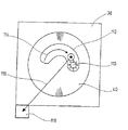
本発明による方法を示す目的で、移動シーケンスの2つの例が図3及び4に示されている。これらはクランピング装置38の概略平面図に関し、そこに工作物40がクランプされている。図3において工作物40は、内側輪郭112をミルする目的で、例としてミリングヘッド110で機械加工される。この場合、ミリングヘッド110は第1(相対)軌道114に沿って、詳細にはNC制御装置70に蓄積された制御セット87を使用することにより、案内される。
For the purpose of illustrating the method according to the invention, two examples of movement sequences are shown in FIGS. These relate to a schematic plan view of the
もし、例えば緊急停止コマンド又は電力供給の中断の結果として、機械加工操作の予定外の中断が生じた場合、工作機械10は未定義状態となる。工作機械10は、好ましくは緊急ルーチンを含むが、これで、例えば最初に述べられたWO 00/66320から公知のように、もし予定外の事象が生じると、ミリングヘッド110が緊急ブレーキのタイプでストップされることが可能である。もっとも、これは新規な方法の実行に全く必要ではない。
If an unscheduled machining operation occurs, for example as a result of an emergency stop command or interruption of power supply, the machine tool 10 will be in an undefined state. The machine tool 10 preferably includes an emergency routine, in which, for example, as is known from the first mentioned WO 00/66320, if an unscheduled event occurs, the milling
新規な方法によれば、ミリングヘッド110は、それが制御された緊急ブレーキの間又は予期されない事象ゆえに制御されない方式で停止されたかどうかとは関係無く、今や自動的に決定された第2軌道116に沿って規定された開始位置118内に移動される。この例において、第2軌道はミリングヘッド110を(スピンドル12を用いて)工作物40から最初にz方向に移動させることを含む。ミリングヘッド110は、次に制御下で開始位置118に移動される。とくに好ましい態様において、規定された開始位置118は工具マガジン44として構成されるが、これは工作機械10がこのようにして有利な基本状態に置かれるためである。加えて、ミリングヘッド110を工具マガジン44に置くことは、ミリングヘッド110の損傷の単純な調査を可能にする。もっとも、原理上は、開始位置118は他の方式でも規定され得る。
According to the new method, the milling
図4は、操作シーケンスについてのもう1つのシナリオを他の同じ仮定のもとで示す。もっとも、図3から明確なように、工作物40はその外側においてミリングヘッド110で機械加工され、すなわち外側輪郭は第1軌道120に沿ってミルされる。このような場合のため、工作機械10の再開の間、ミリングヘッド110を工作物40から放射方向に持って離すことが有利な戦略であることが判明した。その次にのみミリングヘッド110のz方向への退出と、それに続いて開始位置118への移動が行われる。対応する第2軌道が、図4において参照符号122で示されている。
FIG. 4 shows another scenario for the operation sequence under the same other assumptions. However, as is clear from FIG. 3, the
図3及び4から容易に理解できるように、2つの第2軌道116及び122は異なっているが、これは、図3の場合ミリングヘッド110がz方向にすぐに戻され、他方で図4によるシナリオでは、ミリングヘッド110は工作物40から放射方向に最初に持って離されるためである。第2軌道116、122の決定は、それゆえ生産操作の予定外の中断が生じた機械加工操作に依存する。
As can be easily understood from FIGS. 3 and 4, the two
図4の場合、もし、ミリングヘッド110が工作物40の外側輪郭からどれだけ遠く持って離され得るかについての情報を開始論理回路94が有するなら、適当な第2軌道122が有効に決定され得る。対応する距離は図4において参照符号124で示されている。それゆえ、図4に示されたタイプの場合にとって、有効なスペースは、詳細にはNCプログラム87に、パラメータとして好ましく蓄積される。
In the case of FIG. 4, if the starting
有利な典型的な態様において、第2軌道116、122のための種々の制御セットが開始論理回路94に蓄積される。予定外の中断が生じたシナリオの関数としてそれぞれに適当な制御セットが選択される。とくに好ましい選択は、各場合に使用される工具タイプを考慮に入れており、これらは結合されて適当なグループを形成する。1つの典型的な態様において、第2軌道の選択が次のような(要約された)方式で実行される:

表1に示すグループの指定は、独国、とくにシーメンスの工具マネジメントから、NC制御で使用される広範な分類にモデル化されている。もっとも、言うまでもなく、これと異なる他の分類システムもまた使用され得る。 The group designations shown in Table 1 are modeled on the broad classification used in NC control from German , especially Siemens tool management. Of course, other different classification systems may also be used.
とくに好ましい態様において、工具が開始位置として置かれている工具マガジン44のような全ての補助ユニットの協調した駆動が、NC制御装置17の機能性と並行して実行される。この場合、移動シーケンスを操作スピンドルの移動と協調させる目的で、水圧ピストンと他の駆動部を最初に規定された位置に移動する必要があるかもしれない。 In a particularly preferred manner, coordinated driving of all auxiliary units, such as the tool magazine 44 in which the tool is placed as a starting position, is performed in parallel with the functionality of the NC controller 17. In this case, it may be necessary to move the hydraulic piston and the other drive to the first defined position in order to coordinate the movement sequence with the movement of the operating spindle.
後述のフローチャートに関して、本発明による方法の好ましい典型的な態様が更に説明される。 Preferred exemplary embodiments of the method according to the invention are further described with reference to the flowcharts described below.
図5は、工作機械10の全体の操作シーケンスの概観を示す。第1ステップ130において、準備された第2軌道116、122のための制御セットが、ちょうど説明されたシナリオに合わせて読み込まれる。もっとも、好ましくは、これらの準備された第2軌道は、NC制御装置70の読み出し専用メモリ82に製造業者により蓄積される。ステップ132及び134において、軌道の参照点の情報入力、及び機械加工操作のために設けられたNCプログラム86のローディングもまた行われる。ステップ132による参照点の情報入力は、表1の最後に記載された“フォールバック戦略”を可能にする目的で、有利に実行される。もしステップ132による軌道の参照点の情報入力が省略されるなら、このフォールバック戦略を実行することは可能でない。しかしながら、予定外の中断のときに存在するシナリオに基づいて、他の戦略が実行され得る。新規な方法のこの減じられた実行においても、ダウンタイムの顕著な減少が十分に達成される。
FIG. 5 shows an overview of the overall operation sequence of the machine tool 10. In a
ステップ132(軌道の参照点を読み込む)及び134(NCプログラムを読み込む)は、ここで示される表現とは異なり、実行されるべきNCプログラム86内に挿入されている軌道の参照点により、1つのステップに結合され得る。実行に依存して、分離しているが逆のオーダーもまた可能である。
Steps 132 (read trajectory reference points) and 134 (read NC programs) differ from the representation shown here by one of the trajectory reference points inserted in the
ステップ136において、第1軌道114、120を制御するためのNCプログラム86に存在していて第2軌道116、122の適当な決定のために要求される全てのデータは、不揮発性メモリ100に蓄積される。そして、プログラムブロック140、142において、機械加工操作が開始される。プログラムブロック140は、個々の制御セットの実行を、NCプログラム86の文脈の範囲内で記号化し、他方、プログラムブロック142は、これと並行して動くPLCにおける制御コマンドの実行を表現する。矢印は、相互座標のためのデータ交換が2つのプログラムブロックの間で実行され得ることを示している。参照符号144、146は、緊急ルーチンを概念的に示しており、これは、もし予定外の事象が生じた場合、これらの制御システムの文脈の範囲内で実行される。緊急ルーチンを使用することにより、もし予定外の事象が生じるとき、工作機械は停止される。
In
図6は、工作機械10が緊急ルーチン144、146を用いて停止されたあとの操作シーケンスを示す。
FIG. 6 shows an operation sequence after the machine tool 10 is stopped using the
ステップ150において、まず第1に開始コマンドが読み込まれるが、これは工作機械10の再開を開始する目的で機械オペレータによって生成される。プログラムブロック152、154において、好ましくはここで(全てのNC軸のために指定された)操作スピンドル12のため及び工作機械10に属する補助ユニットのための両方と並行に、第2軌道の決定が次に実行される。操作スピンドル12及び補助ユニットは、次にそれらの規定された開始位置に持ち込まれ、これはプログラムブロック156、158で示されている。プログラムステップ160において、中断された機械加工操作が部分的に機械加工された工作物に継続されるべきかどうか又は新しい工作物への生産サイクルが開始されるべきかどうかについて、次に決定がなされる。この原則で、制御は次にNC制御ステップに入り、そこで中断が行われ(ステップ162)、又は第1NC制御ステップ(ステップ164)で再開がなされる。
In
図7は、第2軌道を決定するための好ましい典型的な態様を示す。ステップ170によれば、先ず第1に、工具の種類(工具タイプ)と中断が生じたシナリオが決定される。場合の識別がなされ、これゆえに多数の準備された制御セットから適当な第2軌道のための制御セットが選択される。好ましい典型的な態様において、更に上に示された表に説明された戦略から選択がなされる。異なる戦略が図7において参照符号172、174、176、178、180及び182により示されている。適当な戦略の選択に続いて、そこに保持されている操作スピンドル12及び工具32は、予め規定された第2軌道に沿って開始位置118に持ち込まれる。
FIG. 7 shows a preferred exemplary embodiment for determining the second trajectory. According to step 170, first of all, the type of tool (tool type) and the scenario in which an interruption has occurred are determined. A case identification is made, and therefore a control set for the appropriate second trajectory is selected from a number of prepared control sets. In a preferred exemplary embodiment, a selection is made from the strategies set forth in the tables shown further above. Different strategies are indicated in FIG. 7 by
もう1つの好ましい態様が図8に示されている。この場合、ステップ190において、もう一度予想されない中断が生じたシナリオが決定される。次に、プログラムブロック192において、通過された機械ステップを使用することにより、第2軌道の決定が中断の時間まで実行される。換言すれば、第2軌道は、これまで逆に走行された通過された第1軌道により決定される。この場合の対応する制御データは、不揮発性方式でセーブされたNCプログラム86から作成され得る。
Another preferred embodiment is shown in FIG. In this case, in
Claims (16)
第1制御装置(56、70)にロードされた第1制御プログラム(86)を用いて、第1相対軌道(114、120)に沿う、工作物(40)に対する工具キャリア(12)の移動を制御し、ここで、制御プログラムは、一連の連続する、工具による機械加工操作を規定しており、
予定外の事象が生じた場合に、工具キャリア(12)の相対操作移動を停止し、
開始位置(118)から工具キャリア(12)の相対操作移動を再開する、工作機械(10)を操作する方法であって、
再開の最初に、第2相対軌道(116、122)に沿って、工具キャリア(12)が、停止に続く現在位置から開始位置(118)にまず移動され、その開始位置(118)は、工具による機械加工を再開し得る、工具キャリア(12)の相対位置であり、しかも、その開始位置(118)は、工具キャリア(12)の工具交換位置であり、
第2相対軌道(116、122)は、前述の予定外の事象が生じたときに実行されていた機械加工操作を表すデータに応じ、かつ、第1制御プログラム(86)に規定されている第1相対軌道(114、120)に応じて、開始論理回路(94)によって自動的に決定され、
前述の予定外の事象が、停電、手動による緊急停止、自動停止、意図せずにやってしまった手動の介入からなる群から選ばれた事象であることを特徴とする、工作機械を操作する方法。Relative operational movement of the tool carrier (12) relative to the workpiece (40) along a plurality of relative trajectories (114, 120, 116, 122) including a tool carrier (12) movable relative to the workpiece (40) A first control device (56, 70) for controlling
Using the first control program (86) loaded in the first control device (56, 70), the movement of the tool carrier (12) relative to the workpiece (40) along the first relative trajectory (114, 120). Control, where the control program defines a series of continuous machining operations with the tool,
When an unplanned event occurs, stop the relative movement of the tool carrier (12),
A method of operating a machine tool (10) to resume relative operation movement of a tool carrier (12) from a starting position (118),
At the beginning of the restart, along the second relative trajectory (116, 122), the tool carrier (12) is first moved from the current position following the stop to the start position (118), where the start position (118) The relative position of the tool carrier (12) at which the machining by can be resumed, and its starting position (118) is the tool change position of the tool carrier (12),
The second relative trajectory (116, 122) corresponds to data representing the machining operation that was being performed when the aforementioned unscheduled event occurred, and is defined in the first control program (86). Automatically determined by the start logic circuit (94) in response to one relative trajectory (114, 120),
Operating a machine tool, characterized in that said unscheduled event is an event selected from the group consisting of a power failure, manual emergency stop, automatic stop, unintentional manual intervention Method.
開始位置(118)から工具キャリア(12)の相対操作移動を再開する、金属製の工作物(40)の金属切削機械加工のための工作機械であって、
再開の最初に、第2相対軌道(116、122)に沿って、工具キャリア(12)が、停止に続く現在位置から開始位置(118)にまず移動され、その開始位置(118)は、工具による機械加工を再開し得る、工具キャリア(12)の相対位置であり、しかも、その開始位置(118)は、工具キャリア(12)の工具交換位置であり、
第2相対軌道(116、122)は、前述の予定外の事象が生じたときに実行されていた機械加工操作を表すデータに応じ、かつ、第1制御プログラム(86)に規定されている第1相対軌道(114、120)に応じて、開始論理回路(94)によって自動的に決定され、
前述の予定外の事象が、停電、手動による緊急停止、自動停止、意図せずにやってしまった手動の介入からなる群から選ばれた事象であることを特徴とする工作機械。A first defining a series of successive tool machining operations along a plurality of relative trajectories (114, 120, 116, 122), including a tool carrier (12) movable relative to the workpiece (40). Including a first controller (56, 70) for controlling movement of the tool carrier (12) relative to the workpiece (40) along the first relative trajectory (114, 120) using the control program (86); ,
A machine tool for metal cutting machining of a metal workpiece (40), which resumes relative operating movement of the tool carrier (12) from a starting position (118),
At the beginning of the restart, along the second relative trajectory (116, 122), the tool carrier (12) is first moved from the current position following the stop to the start position (118), where the start position (118) The relative position of the tool carrier (12) at which the machining by can be resumed, and its starting position (118) is the tool change position of the tool carrier (12),
The second relative trajectory (116, 122) corresponds to data representing the machining operation that was being performed when the aforementioned unscheduled event occurred, and is defined in the first control program (86). Automatically determined by the start logic circuit (94) in response to one relative trajectory (114, 120),
A machine tool characterized in that the unscheduled event is an event selected from the group consisting of a power failure, a manual emergency stop, an automatic stop, and an unintentional manual intervention.
Applications Claiming Priority (3)
| Application Number | Priority Date | Filing Date | Title |
|---|---|---|---|
| DE10255033.6 | 2002-11-19 | ||
| DE10255033A DE10255033A1 (en) | 2002-11-19 | 2002-11-19 | Machine tool and method for operating such |
| PCT/EP2003/012321 WO2004046836A1 (en) | 2002-11-19 | 2003-11-05 | Machine tool and method for operating a tool of this type |
Publications (2)
| Publication Number | Publication Date |
|---|---|
| JP2006506719A JP2006506719A (en) | 2006-02-23 |
| JP4947534B2 true JP4947534B2 (en) | 2012-06-06 |
Family
ID=32308703
Family Applications (1)
| Application Number | Title | Priority Date | Filing Date |
|---|---|---|---|
| JP2004552522A Expired - Fee Related JP4947534B2 (en) | 2002-11-19 | 2003-11-05 | Machine tool and method of operating machine tool |
Country Status (7)
| Country | Link |
|---|---|
| US (1) | US7177720B2 (en) |
| EP (1) | EP1522004B1 (en) |
| JP (1) | JP4947534B2 (en) |
| CN (1) | CN100416437C (en) |
| DE (2) | DE10255033A1 (en) |
| ES (1) | ES2256786T3 (en) |
| WO (1) | WO2004046836A1 (en) |
Families Citing this family (11)
| Publication number | Priority date | Publication date | Assignee | Title |
|---|---|---|---|---|
| US7904182B2 (en) * | 2005-06-08 | 2011-03-08 | Brooks Automation, Inc. | Scalable motion control system |
| US8024060B2 (en) * | 2008-06-16 | 2011-09-20 | Electro Scientific Industries, Inc. | Method for defining safe zones in laser machining systems |
| DE102008035710B4 (en) | 2008-07-30 | 2013-01-31 | Jürgen Roleder | Method for automatically returning a tool of a program-controlled machine tool |
| DE102010001518A1 (en) * | 2010-02-02 | 2011-08-04 | DECKEL MAHO Pfronten GmbH, 87459 | Device for controlling operating functions of a machine tool |
| IT1401373B1 (en) | 2010-08-06 | 2013-07-18 | Fidia Spa | PREDICTIVE CONTROL SYSTEM AND VIRTUAL DISPLAY FOR A NUMERICALLY CONTROLLED MACHINE |
| US9946245B2 (en) | 2011-07-25 | 2018-04-17 | Celeritive Technologies, Inc. | Non-concentric milling |
| US10022833B2 (en) | 2012-05-03 | 2018-07-17 | Celeritive Technologies, Inc. | High performance multi-axis milling |
| JP5800869B2 (en) * | 2013-09-09 | 2015-10-28 | ファナック株式会社 | Numerical control device with program restart function |
| JP6013690B2 (en) * | 2014-09-18 | 2016-10-25 | ファナック株式会社 | Numerical control device for approaching the machining restart position |
| TWI668130B (en) * | 2017-03-22 | 2019-08-11 | 三緯國際立體列印科技股份有限公司 | 3d printing device and resume printing method thereof |
| CN111045396A (en) * | 2019-12-24 | 2020-04-21 | 一汽解放汽车有限公司 | One-key origin point returning method for domestic numerical control machining center Fanuc operating system |
Family Cites Families (22)
| Publication number | Priority date | Publication date | Assignee | Title |
|---|---|---|---|---|
| NO115175B (en) | 1966-11-29 | 1968-08-19 | Kongsberg Vapenfab As | |
| GB2082346B (en) | 1980-07-04 | 1984-05-16 | Komatsu Mfg Co Ltd | Method and device for automatically retreating and returning a tool in a machine tool |
| NL8203413A (en) * | 1982-09-01 | 1984-04-02 | Philips Nv | METHOD FOR REMOVING AND RETURNING TO A WORK FROM A TOOL IN THE MACHINING PROCESSING OF THAT NUMBER-CONTROLLED TOOL MACHINE AND NUMBER-CONTROLLED TOOL FOR CARRYING OUT THE WORK. |
| JPS59152050A (en) * | 1983-02-15 | 1984-08-30 | Fanuc Ltd | Restart of profiling operation |
| JPS60157607A (en) * | 1984-01-26 | 1985-08-17 | Fanuc Ltd | Numerical control method |
| JPS6288546A (en) * | 1985-10-15 | 1987-04-23 | Hitachi Seiki Co Ltd | Device for siding and handling broken tool in fms |
| JPH01146642A (en) * | 1987-12-03 | 1989-06-08 | Fanuc Ltd | Stop control device for cutting tool |
| JP2608593B2 (en) * | 1988-08-26 | 1997-05-07 | ファナック株式会社 | Failure diagnosis method |
| JPH0725006B2 (en) * | 1989-03-27 | 1995-03-22 | オ−クマ株式会社 | Tool withdrawal method and apparatus for numerically controlled machine tool |
| US5414633A (en) * | 1992-12-21 | 1995-05-09 | Industrial Technology Research Institute | Path control method of tool withdrawal and resumption in CNC |
| EP0766154B1 (en) * | 1992-12-28 | 2000-03-29 | Mitsubishi Denki Kabushiki Kaisha | Numerically controlled machine tool and method |
| JP3526070B2 (en) * | 1993-03-31 | 2004-05-10 | 株式会社安川電機 | Numerical control device and numerical control machining method |
| JP3276248B2 (en) * | 1994-08-02 | 2002-04-22 | 株式会社小松製作所 | Error recovery device |
| JP3369346B2 (en) * | 1995-02-21 | 2003-01-20 | ファナック株式会社 | Power outage control device |
| JPH09117827A (en) * | 1995-10-25 | 1997-05-06 | Fanuc Ltd | Diesinking electric discharge machine controller and contouring work of diesinking electric discharge machine |
| JPH09184068A (en) * | 1995-12-28 | 1997-07-15 | Canon Inc | Management and display control of manufacturing process of continuum |
| DE19614134C2 (en) * | 1996-04-10 | 2002-06-13 | Agie Sa | Wire EDM machine and method for its operation |
| JPH1153018A (en) * | 1997-08-01 | 1999-02-26 | Graphic Prod:Kk | Control method of cutting device |
| JP2917215B2 (en) * | 1997-10-28 | 1999-07-12 | 株式会社日立製作所 | Welding robot controller |
| DE19919692A1 (en) * | 1999-04-30 | 2000-11-09 | Stama Maschinenfabrik Gmbh | Machine tool with mechanical energy storage |
| JP3177601B2 (en) * | 1999-06-02 | 2001-06-18 | ファナック株式会社 | Numerical control unit |
| JP2002123306A (en) * | 2000-10-17 | 2002-04-26 | Toshiba Mach Co Ltd | Monitor system for machine tool |
-
2002
- 2002-11-19 DE DE10255033A patent/DE10255033A1/en not_active Ceased
-
2003
- 2003-11-05 CN CNB2003801036424A patent/CN100416437C/en not_active Expired - Fee Related
- 2003-11-05 EP EP03775296A patent/EP1522004B1/en not_active Expired - Fee Related
- 2003-11-05 DE DE50302353T patent/DE50302353D1/en not_active Expired - Lifetime
- 2003-11-05 WO PCT/EP2003/012321 patent/WO2004046836A1/en active IP Right Grant
- 2003-11-05 JP JP2004552522A patent/JP4947534B2/en not_active Expired - Fee Related
- 2003-11-05 ES ES03775296T patent/ES2256786T3/en not_active Expired - Lifetime
-
2005
- 2005-05-19 US US11/134,570 patent/US7177720B2/en not_active Expired - Lifetime
Also Published As
| Publication number | Publication date |
|---|---|
| US7177720B2 (en) | 2007-02-13 |
| CN1714320A (en) | 2005-12-28 |
| ES2256786T3 (en) | 2006-07-16 |
| US20050209730A1 (en) | 2005-09-22 |
| DE50302353D1 (en) | 2006-04-13 |
| CN100416437C (en) | 2008-09-03 |
| EP1522004B1 (en) | 2006-02-01 |
| JP2006506719A (en) | 2006-02-23 |
| DE10255033A1 (en) | 2004-06-09 |
| EP1522004A1 (en) | 2005-04-13 |
| WO2004046836A1 (en) | 2004-06-03 |
Similar Documents
| Publication | Publication Date | Title |
|---|---|---|
| US7177720B2 (en) | Machine tool and method for operating a machine tool | |
| RU2348498C2 (en) | Method and device for automatic replacement of tool in metal-cutting lathe controlled by numerical control (nc) device | |
| CN102667650B (en) | Numerical control machine tool | |
| EP1243992B1 (en) | Tool presetter and tool offset amount calculation method | |
| JP3990441B1 (en) | Automatic tool changing method and automatic tool changing device for machine tool with numerical control device | |
| KR20040060741A (en) | A Tool Error Detecting Unit of CNC and Method Thereof | |
| CN101109947A (en) | Numerical controller having interference check function | |
| JPH046001B2 (en) | ||
| US20220244701A1 (en) | Control Device for Use on a Numerically Controlled Machine Tool, and Machine Tool Comprising a Control Device | |
| JPS59184911A (en) | Method of copying contour of work with tool | |
| KR930010589B1 (en) | Cutting tool stop control apparatus | |
| JP2006075916A (en) | Protective cover opening/closing device for machine tool | |
| JPS6365469B2 (en) | ||
| US20190121325A1 (en) | Numerical controller | |
| JP3171298B2 (en) | Numerically controlled machine tools | |
| US20190202017A1 (en) | Selecting device, selecting method, and program | |
| JP2000284817A (en) | Numerical controller to simultaneously control two movable objects no common track | |
| JP4859467B2 (en) | How to restart a 2-spindle facing lathe | |
| JP3435229B2 (en) | Machining method by NC lathe and NC lathe capable of backup machining | |
| JPH08263115A (en) | Interference evading method for nc machine tool | |
| JPH11202926A (en) | Method and device for feed speed control in numerical control | |
| US10564630B2 (en) | Numerical controller | |
| CN114945876A (en) | Numerical controller, chip removal system, and chip removal method | |
| JP4261708B2 (en) | NC machining equipment | |
| JP3587046B2 (en) | Numerical control device that simultaneously controls two movable bodies on a common path |
Legal Events
| Date | Code | Title | Description |
|---|---|---|---|
| A621 | Written request for application examination |
Free format text: JAPANESE INTERMEDIATE CODE: A621 Effective date: 20060731 |
|
| A131 | Notification of reasons for refusal |
Free format text: JAPANESE INTERMEDIATE CODE: A131 Effective date: 20090609 |
|
| A601 | Written request for extension of time |
Free format text: JAPANESE INTERMEDIATE CODE: A601 Effective date: 20090731 |
|
| A601 | Written request for extension of time |
Free format text: JAPANESE INTERMEDIATE CODE: A601 Effective date: 20090803 |
|
| A602 | Written permission of extension of time |
Free format text: JAPANESE INTERMEDIATE CODE: A602 Effective date: 20090807 |
|
| A602 | Written permission of extension of time |
Free format text: JAPANESE INTERMEDIATE CODE: A602 Effective date: 20090810 |
|
| A601 | Written request for extension of time |
Free format text: JAPANESE INTERMEDIATE CODE: A601 Effective date: 20090904 |
|
| A602 | Written permission of extension of time |
Free format text: JAPANESE INTERMEDIATE CODE: A602 Effective date: 20090911 |
|
| A521 | Written amendment |
Free format text: JAPANESE INTERMEDIATE CODE: A523 Effective date: 20091204 |
|
| A02 | Decision of refusal |
Free format text: JAPANESE INTERMEDIATE CODE: A02 Effective date: 20100518 |
|
| A521 | Written amendment |
Free format text: JAPANESE INTERMEDIATE CODE: A523 Effective date: 20100903 |
|
| A911 | Transfer to examiner for re-examination before appeal (zenchi) |
Free format text: JAPANESE INTERMEDIATE CODE: A911 Effective date: 20101020 |
|
| A912 | Re-examination (zenchi) completed and case transferred to appeal board |
Free format text: JAPANESE INTERMEDIATE CODE: A912 Effective date: 20101119 |
|
| A601 | Written request for extension of time |
Free format text: JAPANESE INTERMEDIATE CODE: A601 Effective date: 20110823 |
|
| A602 | Written permission of extension of time |
Free format text: JAPANESE INTERMEDIATE CODE: A602 Effective date: 20110829 |
|
| A601 | Written request for extension of time |
Free format text: JAPANESE INTERMEDIATE CODE: A601 Effective date: 20110907 |
|
| A602 | Written permission of extension of time |
Free format text: JAPANESE INTERMEDIATE CODE: A602 Effective date: 20110912 |
|
| A521 | Written amendment |
Free format text: JAPANESE INTERMEDIATE CODE: A523 Effective date: 20111209 |
|
| A521 | Written amendment |
Free format text: JAPANESE INTERMEDIATE CODE: A523 Effective date: 20120124 |
|
| A01 | Written decision to grant a patent or to grant a registration (utility model) |
Free format text: JAPANESE INTERMEDIATE CODE: A01 |
|
| A61 | First payment of annual fees (during grant procedure) |
Free format text: JAPANESE INTERMEDIATE CODE: A61 Effective date: 20120228 |
|
| FPAY | Renewal fee payment (event date is renewal date of database) |
Free format text: PAYMENT UNTIL: 20150316 Year of fee payment: 3 |
|
| R150 | Certificate of patent or registration of utility model |
Ref document number: 4947534 Country of ref document: JP Free format text: JAPANESE INTERMEDIATE CODE: R150 Free format text: JAPANESE INTERMEDIATE CODE: R150 |
|
| R250 | Receipt of annual fees |
Free format text: JAPANESE INTERMEDIATE CODE: R250 |
|
| R250 | Receipt of annual fees |
Free format text: JAPANESE INTERMEDIATE CODE: R250 |
|
| R250 | Receipt of annual fees |
Free format text: JAPANESE INTERMEDIATE CODE: R250 |
|
| R250 | Receipt of annual fees |
Free format text: JAPANESE INTERMEDIATE CODE: R250 |
|
| R250 | Receipt of annual fees |
Free format text: JAPANESE INTERMEDIATE CODE: R250 |
|
| LAPS | Cancellation because of no payment of annual fees |