WO2023210824A1 - 振動アクチュエータ及び接触型入力装置 - Google Patents
振動アクチュエータ及び接触型入力装置 Download PDFInfo
- Publication number
- WO2023210824A1 WO2023210824A1 PCT/JP2023/016959 JP2023016959W WO2023210824A1 WO 2023210824 A1 WO2023210824 A1 WO 2023210824A1 JP 2023016959 W JP2023016959 W JP 2023016959W WO 2023210824 A1 WO2023210824 A1 WO 2023210824A1
- Authority
- WO
- WIPO (PCT)
- Prior art keywords
- plate
- vibration actuator
- vibration
- coil
- core
- Prior art date
- Legal status (The legal status is an assumption and is not a legal conclusion. Google has not performed a legal analysis and makes no representation as to the accuracy of the status listed.)
- Ceased
Links
Images


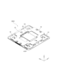
Classifications
-
- B—PERFORMING OPERATIONS; TRANSPORTING
- B06—GENERATING OR TRANSMITTING MECHANICAL VIBRATIONS IN GENERAL
- B06B—METHODS OR APPARATUS FOR GENERATING OR TRANSMITTING MECHANICAL VIBRATIONS OF INFRASONIC, SONIC, OR ULTRASONIC FREQUENCY, e.g. FOR PERFORMING MECHANICAL WORK IN GENERAL
- B06B1/00—Methods or apparatus for generating mechanical vibrations of infrasonic, sonic, or ultrasonic frequency
- B06B1/02—Methods or apparatus for generating mechanical vibrations of infrasonic, sonic, or ultrasonic frequency making use of electrical energy
- B06B1/04—Methods or apparatus for generating mechanical vibrations of infrasonic, sonic, or ultrasonic frequency making use of electrical energy operating with electromagnetism
- B06B1/045—Methods or apparatus for generating mechanical vibrations of infrasonic, sonic, or ultrasonic frequency making use of electrical energy operating with electromagnetism using vibrating magnet, armature or coil system
-
- G—PHYSICS
- G06—COMPUTING OR CALCULATING; COUNTING
- G06F—ELECTRIC DIGITAL DATA PROCESSING
- G06F3/00—Input arrangements for transferring data to be processed into a form capable of being handled by the computer; Output arrangements for transferring data from processing unit to output unit, e.g. interface arrangements
- G06F3/01—Input arrangements or combined input and output arrangements for interaction between user and computer
- G06F3/016—Input arrangements with force or tactile feedback as computer generated output to the user
-
- H—ELECTRICITY
- H02—GENERATION; CONVERSION OR DISTRIBUTION OF ELECTRIC POWER
- H02K—DYNAMO-ELECTRIC MACHINES
- H02K33/00—Motors with reciprocating, oscillating or vibrating magnet, armature or coil system
- H02K33/02—Motors with reciprocating, oscillating or vibrating magnet, armature or coil system with armatures moved one way by energisation of a single coil system and returned by mechanical force, e.g. by springs
Definitions
- the present invention relates to a vibration actuator and a contact type input device equipped with the same.
- Patent Document 1 a configuration has been known in which a vibration actuator applies vibration to the pad of a finger of an operator who has touched a display screen displayed on a touch panel, which is a sensing panel, as a touch operation feeling (a feeling of touching and operating).
- Patent Document 1 discloses a mobile terminal device in which a vibration actuator is attached to the back surface of a touch panel via a vibration transmission section.
- a vibration actuator of this device a movable element is arranged in a housing fixed to a vibration transmitting part so as to be reciprocating along a guide shaft arranged perpendicularly to the touch panel.
- the movable element collides with the housing in response to an operation on the touch panel, which may generate a collision sound, but it does not apply vibration to the pad of the finger that contacts the touch panel via the vibration transmission part. ing.
- the movable element is reciprocated along a guide shaft arranged perpendicular to the display surface of the touch panel, so the device itself has a length perpendicular to the display surface. , that is, the structure has a thickness.
- This configuration requires an arrangement space for a predetermined thickness on the back side of the touch panel, and there is a problem that the mobile terminal device itself equipped with the touch panel becomes large.
- the movable element includes a magnet and two yokes sandwiching the magnet
- the stator includes a bobbin surrounding the movable body and two coils wound around the bobbin. It takes time to assemble. Therefore, there is a desire to further reduce the number of parts and improve assembly efficiency.
- An object of the present invention is to provide a vibration actuator and a contact type input device that are easy to assemble, are arranged in a small space, and vibrate suitably.
- the vibration actuator of the present invention includes: a magnetic plate, a flat electromagnet disposed on the plate and having a coil in the center of the core; a flat elastic body that supports the electromagnet with an axis of the coil arranged parallel to the plate and with a space between it and the plate; A configuration is adopted in which one of the coil or the plate is displaced to approach the other and vibrates due to the magnetic force generated by energizing the coil.
- the contact input device of the present invention includes: A contact type input device in which a vibration actuator having the above configuration is arranged on the back side of an operation surface, The coil is energized in response to the operator's touch action on the operation surface, and one of the coil or the plate is displaced and vibrated to approach the other, thereby presenting a tactile sensation to the operator.
- the present invention it is easy to assemble, and it can be arranged in a small space and vibrate suitably.
- FIG. 1 is an exploded perspective view of a vibration actuator according to an embodiment of the present invention. It is an exploded perspective view showing the relationship between a movable part and an elastic support part in a vibration actuator concerning one embodiment of the present invention.
- FIGS. 11A, 11B, and 11C are diagrams for explaining the operation of the vibration actuator. It is a figure showing an example of the drive circuit of an actuator main part.
- FIG. 1 is an external perspective view showing an example of a vibration presentation device having a vibration actuator.
- FIG. 2 is a schematic side sectional view showing the main part configuration of the vibration presentation device.
- FIGS. 15A and 15B are diagrams showing tactile sensations provided by the vibration presentation device in time series. It is a schematic side sectional view showing a modification of the same vibration presentation device.
- the width, depth, and height of the vibration presentation device (contact type input device) 1 having the vibration actuator 10 are the lengths in the X direction, Y direction, and Z direction, respectively, and the width and depth of the vibration actuator 10 are the lengths in the X direction, Y direction, and Z direction, respectively.
- the heights correspond to the lengths in the X direction, Y direction, and Z direction.
- the positive side in the Z direction is the direction in which vibration feedback is given to the operator (operator), and is defined as the “flat side” (or “upper side")
- the negative side in the Z direction is the direction in which the operator presses when operating. direction, and will be described as the “bottom side” (or “lower side”).
- the surface on the "plane side” is referred to as the “front surface” (or “upper surface")
- the surface on the "back side” or “lower side”
- the surface will be described as the “back surface” (or "bottom surface”).
- the vibration actuator 10 is a vibration presentation device (see FIG. 13)).
- the vibration actuator 10 vibrates the operating device, thereby imparting a touch operation feeling (also referred to as "tactile sensation” or “force sensation”) to the operator who touches and operates the operating device, depending on the purpose and usage status of the operating device. can do.
- a touch operation feeling also referred to as "tactile sensation” or “force sensation”
- the vibration actuator 10 is a thin vibration actuator in the form of a flat plate or a thin plate, and if the Z direction is the thickness direction, it is disposed opposite to the back side of the operating device in the thickness direction so that the operating device can vibrate.
- the vibration actuator 10 is formed into a thin plate shape, and includes a movable part 20, a base part (hereinafter also referred to as a "base plate") 30, and an elastic support that supports the movable part 20 movably with respect to the base part 30. It has a plate-like elastic part 40 as a part (elastic body).
- the elastic support part is made into the plate-shaped elastic part 40, it is not limited to a plate-shape as long as it supports the movable part 20 movably with respect to the base part 30.
- the vibration actuator 10 can be connected via one of the movable part 20 and the base part 30 to a vibration presentation part (for example, the pad main bodies 110 and 110A shown in FIGS. 14 to 16) that receives a user's pressing operation. .
- a vibration presentation part for example, the pad main bodies 110 and 110A shown in FIGS. 14 to 16
- the vibration actuator 10 allows the movable part 20 to vibrate by moving towards and away from the base part 30 in the Z direction, specifically towards the base part 30 side, so that the vibration can be absorbed by the operation to which the vibration actuator 10 is attached. Gives a sense of operation to the device.
- the movable part 20 is formed into a rectangular plate shape and includes a coil 22, a core 24, and a weight part 26.
- the coil is formed into a flat shape and is arranged so as to surround the center portion of the core 24.
- the coil 22 is disposed around the outer periphery of the central portion of the core 24 with an insulating material interposed therebetween.
- the insulating material may be, for example, a coating agent that is applied to the core 24 and hardened, or may be configured as a bobbin-shaped insulating member and interposed between the coil 22 and the core 24.
- a resin material such as polybutylene terephthalate (PBT) is used, thereby ensuring electrical insulation between the coil 22 and the core 24.
- the core (magnetic core) 24 is a magnetic material, and both ends 24a and 24b in the direction of the winding axis protrude from the coil 22, that is, both ends 24a and 24b protrude from the coil 22 being wound.
- Spring connecting parts 241 and 242 are provided at the tips of both ends 24a and 24b of the core 24, respectively, to be joined to the elastic support parts.
- the core 24 is formed into a rectangular plate shape, and both end portions 24a and 24b each have a wide rectangular plate shape, and face the base portion 30 on the back side.
- a weight portion 26 extending over the spring connection portions 241 and 242 is attached to the surfaces of both end portions 24a and 24b.
- the weight portion 26 is plate-shaped and provided corresponding to the shape of the core 24, for example, the width (length in the X direction) and the length in the depth direction (length in the Y direction).
- the weight can be set arbitrarily, and can be adjusted by, for example, adjusting the length of the weight portion 26 in the Y direction, adjusting the length in the Z direction, or adjusting the material. In this way, the weight part 26 can adjust the weight of the movable part 20, and by this adjustment, the natural frequency can be set. Note that if the thickness (Z direction) arrangement space is limited, a shape may be used in which the weight increases in the XY directions.
- the weight unit 26 is attached to the weight via a fixing material such as an adhesive, a fixing member, or an adhesive material. It is preferable that a vibration presentation section is attached to the section 26.
- the core 24 is magnetized by energizing the coil 22 and functions as an electromagnet. Both end portions 24a and 24b serve as magnetic poles, and generate a magnetic attraction force between them and the adjacent magnetic body, that is, the base portion 30.
- the core 24 is preferably formed of a soft magnetic material such as a silicon steel plate, permalloy, or ferrite.
- the core 24 may be made of electromagnetic stainless steel, sintered material, MIM (metal injection mold) material, laminated steel plate, electrogalvanized steel plate (SECC), or the like.
- the base portion 30 supports the movable portion 20 so as to be movable in the approaching and separating direction of the base portion 30, in the Z direction in FIG. 1, via the plate-like elastic portion 40.
- the base portion 30 includes opposing portions 32a and 32b, which are magnetic materials, which are arranged to face both ends 24a and 24b of the core 24 with a gap G in the opposite direction intersecting the winding axis direction of the coil 22. has.
- the base portion 30 is a flat member having a predetermined thickness in the Z direction, and forms the bottom surface of the vibration actuator 10.
- the base part 30 has a base main body part 31 which is a magnetic material, and the base main body part 31 includes opposing parts (magnetic material) 32a and 32b arranged to face both ends 24a and 24b, and an elastic part connecting part. Certain spring connections 34a, 34b and a fixing part 36 are provided.
- the base main body portion 31 has an opening 38 in the center and is formed into a square frame shape in plan view.
- the opening 38 is a space into which the lower part of the coil 22 is inserted, and has a shape corresponding to the outer shape of the coil 22, for example, a square shape.
- opposing portions 32a and 32b are formed on each of a pair of side portions 311 facing and spaced apart from each other, and between the pair of side portions 311, another pair of side portions 312 facing and spaced apart from each other are formed.
- Spring fixing portions 34a and 34b are formed in each of the spring fixing portions 34a and 34b.
- the opposing parts 32a, 32b and the spring fixing parts 34a, 34b are each formed on the surface of the base main body part 31, that is, the surface on the movable part side.
- the pair of sides 311 and the other pair of sides 312 are each planar, and cutouts 311a and 312a are formed in the center of the four outer edges that make up the outer periphery of the base body 31, respectively. has been done.
- the cutout portions 311a and 312a are each provided to secure a partial deformation region of the plate-like elastic portion 40 to be placed.
- the opposing parts (opposing surfaces) 32a and 32b are part of the base part 30, and have a gap in the opposite direction intersecting the winding axis direction of the coil 22, for example, in the Z direction, with respect to both ends 24a and 24b of the core 24.
- the opposing parts 32a, 32b are attracted to both ends 24a, 24b by magnetic attraction force generated between the opposite sides of the ends 24a, 24b when the coil 22 is energized.
- the opposing parts 32a and 32b are formed, for example, at the center of each of the pair of side parts 311, and are arranged at positions sandwiching the opening 38 in the Y direction.
- the opposing parts 32a and 32b are part of the base body part 31 and are made of ferromagnetic material, such as iron (Fe), cobalt (Co), nickel (Ni), gadolinium (Gd), or the like.
- the opposing parts 32a, 32b, together with the spring connecting parts 34a, 34b and the fixing part 36, are formed as the base main body part 31, particularly from a metal material (for example, iron) such as iron, cobalt, or nickel.
- Both end portions 24a and 24b are arranged to face each other apart from each other above the opposing portions 32a and 32b (in the Z direction), and are symmetrical about the centers in the X direction and the Y direction.
- the spring connecting parts 34a and 34b are arranged so as to sandwich the opening 38 in the X direction, and are joined to the other end of the plate-shaped elastic part 40 on the surface side of the base part 30.
- the fixing part 36 fixes the base part 30.
- the fixing part 36 is attached to an operating device (vibration presentation section) that is touched and operated by the operator, or a casing (arrangement section) in which the operating device is arranged, via a fastening member (for example, a screw 170 shown in FIG. 13). ) (see FIGS. 2, 3, and 13).
- the fixing parts 36 are formed at the four corners of the base part 30, and can securely attach and fix the base part 30 to the object to be fixed. Although the fixing parts 36 are formed at the four corners, the number of fixing parts 36 may be any number as long as the base part 30 can be fixed to the object to be fixed.
- the plate-shaped elastic part 40 is plate-shaped, specifically, is a plate spring that is elastically deformed, and supports the movable part 20 movably with respect to the base part 30.
- the plate-like elastic part 40 is formed in the shape of a thin plate frame having a predetermined thickness (thickness in the Z direction), and is arranged in a layer between the base part 30 and the movable part 20 in the thickness direction (Z direction).
- the plate-like elastic part 40 is connected to each of the movable part 20 and the base part 30.
- the plate-like elastic part 40 is formed in a frame shape surrounding the base part 30, and the movable part 20 is joined to each of a pair of mutually parallel side parts 461.
- the base portion 30 is joined to each of the pair of side portions 462 .
- the plate-like elastic part 40 moves the movable part 20 in the directions (X direction and Y direction) perpendicular to the direction (vibration direction) facing the base part 30. ) to support it in a symmetrical and well-balanced manner.
- the plate-like elastic part 40 is a rectangular frame body (here, a thin plate frame body), the number of parts can be reduced and the overall thickness can be reduced, and furthermore, it can be manufactured without bending parts etc. . Furthermore, since it is a frame, other parts can be placed within the frame so as not to interfere with other parts.
- the plate-like elastic part 40 can determine the amount of displacement and natural frequency of the movable part 20 by setting the spring constant Ksp , and when driving the movable part 20, that is, when energizing the coil 22, The displacement produces a mechanical tactile sensation.
- the plate-shaped elastic part 40 connects the movable part side fixed parts 42a, 42b, the base part side fixed parts 44a, 44b, and the movable part side fixed parts 42a, 42b and the base part side fixed parts 44a, 44b, and is elastically deformed. It has a planar elastic main body part 46 including an arm.
- the elastic main body portion 46 connects the movable portion side fixing portions 42a, 42b and the base portion side fixing portions 44a, 44b so as to be elastically deformable in the Z direction.
- the elastic main body portion 46 has a deformable arm portion that connects the movable portion side fixing portions 42a, 42b and the base portion side fixing portions 44a, 44b.
- the arm part is formed into an L-shape, so that it has a frame shape that surrounds the base part 30 in plan view, and is deformable in the Z direction on the outer peripheral side of the base part 30.
- the movable portion side fixing portions 42a and 42b and one side of the L-shaped arm linearly connected to these constitute a pair of mutually parallel side portions 461, and a side portion adjacent to these pair of side portions 461
- Base portion side fixing portions 44a and 44b are formed on the other pair of matching side portions 462 so as to protrude inwardly.
- the elastic main body part 46 In the plate-shaped elastic part 40, the elastic main body part 46, the movable part side fixing parts 42a and 42b, and the base part side fixing parts 44a and 44b are arranged on the same plane.
- the movable part side fixing parts 42a and 42b are planar and fixed to the movable part 20.
- the movable part side fixing parts 42a and 42b are provided at the center of a pair of side parts 311 arranged on the outside of the base part 30 in the elastic main body part 46 when viewed from above, and are attached to the spring connection part of the core 24 on the surface. It is fixed in surface contact with 241 and 242 on the back side.
- the movable part side fixing parts 42a and 42b are provided so as to be symmetrical in each direction with respect to the center in the X direction or the center in the Y direction.
- the base-side fixing parts 44a and 44b have a planar shape and are fixed to the base part 30.
- the plate-shaped elastic part 40 has an arm of the elastic main body part 46 in order to ensure elasticity, and this arm shape allows the movable part side fixing parts 42a, 42b and the base part side fixing parts 44a, 44b to be displaced in the Z direction. Any shape may be used as long as it can be freely connected. Further, the elastic main body portion 46 may have any shape as long as it is formed to deform in a well-balanced manner so as to move the movable portion 20 in the Z direction (vibration imparting direction) with the movable portion 20 positioned on the XY plane. .
- the plate-like elastic portion 40 is configured such that the back surfaces of both ends of the movable portion 20 and the opposing portions 32a and 32b of the base portion 30 face each other with a gap G in the vibration direction (Z direction) that is perpendicular to each other.
- the movable part 20 is supported.
- the plate-like elastic portion 40 forms a gap G depending on its thickness (length in the Z direction).
- the plate-like elastic portion 40 deforms between the top surface of the core 24 or coil 22 and the bottom surface of the base portion 30.
- the plate-like elastic part 40 is formed into a rectangular frame shape, and the movable part side fixing parts 42a, 42b and the base part side fixing parts 44a, 44b are located in the center of each side of the rectangular frame. It is located.
- the movable part 20 is driven, the movable part side fixing parts 42a and 42b are displaced with respect to the base part side fixing parts 44a and 44b.
- the movable part 20 is supported on both sides of the elastic main body part 46 by L-shaped arms that connect to the movable part side fixing parts 42a, 42b and the base part side fixing parts 44a, 44b. Therefore, it is possible to disperse stress during elastic deformation, and the movable part 20 can be moved in the vibration direction (Z direction) without tilting with respect to the base part 30, improving the reliability of the vibration state. Stability can be improved.
- FIGS. 11A to 11C are diagrams for explaining the operation of the vibration actuator. Note that FIGS. 11A to 11C are perspective views of the vibration actuator 10 showing a section taken along line BB in FIG. has.
- FIG. 11A is a diagram showing a resting state of the vibration actuator 10 (located at a resting position SI).
- a current is applied to the coil 22 of the vibration actuator 10 shown in FIG. 11A
- the core 24 is excited to generate a magnetic field, and both ends 24a and 24b of the core 24 become magnetic poles.
- FIG. 11B in the core 24, one end 24a is the north pole, and the other end 24b is the south pole.
- a magnetic circuit indicated by the flow M of magnetic flux is formed between the core 24 and the opposing parts 32a and 32b of the base part 30.
- a flow M of magnetic flux in this magnetic circuit flows from one end portion 24a to the opposing portion 32a, reaches the opposing portion 32b from the opposing portion 32a, flows from the opposing portion 32b to the other end portion 24b of the core 24, and flows through the core 24.
- the light is emitted again from one end 24a.
- both ends 24a and 24b of the core 24 generate a magnetic attraction force KR according to the principle of an electromagnetic solenoid. Then, both end portions 24a and 24b are attracted to both opposing portions 32a and 32b of base portion 30. Since the base portion 30 is fixed to a housing or the like via a fixing portion 36, both end portions 24a and 24b are attracted and attracted to the opposing portions 32a and 32b. That is, the plate-like elastic portion 40 is deformed and the movable portion 20 is drawn toward the base portion 30 side. The movable part 20 is arranged close to the position (KI) where the base part 30 is fixed.
- the movable portion 20 may be moved back and forth in the Z direction by repeatedly energizing and disabling the coil 22 to generate vibrations.
- the vibration actuator 10 when the movable part 20, which is supported in a suspended state with respect to the base part 30 by the plate-like elastic part 40, is energized, the electromagnet and the opposing parts 32a and 32b, which are magnetic bodies, are connected. Due to the generated magnetic attraction force, it is mechanically displaced and then freely vibrates.
- the vibration actuator 10 causes the movable part 20 to move toward the base part 30 due to the magnetic attraction force generated between the core 24 and the opposing parts (magnetic bodies) 32a and 32b when the coil 22 is energized. let This movement causes the movable part 20 to vibrate due to the elastic force (biasing force) generated in the plate-like elastic part 40, giving a tactile sensation to the user.
- the core 24 around which the coil 22 is wound is movable in the Z direction with respect to the base part 30 by the plate-shaped elastic part 40 with the coil 22 inserted through the opening 38 of the base part 30.
- the vibration actuator 10 can be configured with only the height of the thin plate-shaped core 24, the portion of the coil 22 on the core 24, the plate-shaped elastic part 40, and the base part 30 stacked together.
- the vibration actuator 10 can be configured in a thin plate shape, and the installation space can be saved.
- this configuration is compared to a configuration in which members that generate magnetism and drive a movable part in the Z direction are stacked in the Z direction, such as arranging a coil and a magnet facing each other in the Z direction. It has an even thinner structure.
- the plate-shaped core 24 is disposed perpendicularly facing the opposing parts 32a and 32b of the base part 30, and the movable part 20 is a plate that is a plate spring disposed between the core 24 and the base part 30. It is held movably in the vertical direction (vibration direction) via a shaped elastic part 40. Thereby, the core 24 is supported so as to be able to freely vibrate with respect to the base portion 30 with a space equal to the thickness of the plate-like elastic portion 40 being secured as a gap for vibration.
- the base portion 30 has a plate shape provided with an opening 38 through which the coil 22 is inserted so as to be movable in opposite directions.
- a vibration presentation part for example, the pad main body 110, 110A in FIGS. 14 to 16
- a fixing portion 36 is provided for fixing to the bottom portion 120 of FIGS. 14-16, for example.
- the plate-like elastic part 40 extends so as to surround the base part 30 on the outside of the fixing part 36. Thereby, the plate-like elastic part 40 can be elastically deformed without interfering with the fixation of the base part 30, and the stroke for the elastic deformation can be secured.
- the vibration actuator 10 all components such as the base part 30, the plate-like elastic part 40, the movable part 20, and the weight part 26 are assembled in the Z direction, that is, in the thickness direction, so that they can be easily assembled. Therefore, it is possible to manufacture a vibration actuator that is driven stably and with little variation during assembly.
- the vibration actuator 10 has a configuration in which the distance between the core 24 and the base portion 30 is ensured by the thickness of the plate-like elastic portion 40. This eliminates the need to provide a separate member to form the distance between the core 24 and the base portion 30, further reducing the number of parts, reducing size, simplifying assembly, and lowering costs. can be achieved.
- the plate-shaped elastic part 40 is a plate spring with high thickness precision during manufacture, variations in the gap between the core 24 and the base part 30 (specifically, the opposing parts 32a and 32b) are suppressed. and is secured as a stable gap. Since the surfaces of both end portions 24a and 24b of the core 24 are exposed, the weight on the movable portion 20 side can be easily increased using the surface space.
- vibration is generated by moving the movable part 20 in a reciprocating straight line without using a magnet
- the cost can be reduced compared to a configuration using a magnet.
- the number of parts can be reduced and manufacturing can be facilitated.
- the vibration actuator 10 it is easy to assemble and is thin, so it can be placed in a space-saving manner and vibrates suitably. Further, the vibration actuator 10 can be made thinner and smaller, and can provide a suitable tactile sensation corresponding to the user's pressing operation on the vibration presentation section.
- the vibration actuator 10 can also be driven by generating a resonance phenomenon using pulses using the following equation of motion and circuit equation. Note that the operation is not a resonance drive, but expresses the feeling of operation with a trackpad (see FIG. 13) as the vibration presentation device 100. For example, a current pulse (single or plural It may also be driven by inputting a value (good).
- the movable part 20 in the vibration actuator 10 performs reciprocating motion based on equations (1) and (2).
- the vibration in the vibration actuator 10 is determined by the mass m of the movable part 20 and the spring constant K sp of the metal spring (a plate spring in this embodiment) as the plate-like elastic part 40. Further, the vibration generated by the vibration actuator 10 can be set by the input voltage (pulse) and the degree of damping of the vibration damping part (such as the damper part 190 shown in FIG. 14) if there is a vibration damping part (such as the damper part 190 shown in FIG. 14).
- the base portion 30 and the plate-like elastic portion 40 are joined together, and the plate-like elastic portion 40 and the movable portion 20 are joined together using an adhesive as a fixing member, welding, or the like. It is fixed.
- a screw may be used as the fastening member.
- FIG. 12 shows an example of a drive circuit for the actuator body.
- the drive circuit shown in FIG. 12 is included in the control section, for example.
- the drive circuit is a switching element 12 as a current pulse supply unit (Signal Generat Department (Signal Generat) (Signal Generat) (Signal Generat). Ion) 14, resistance R1, R2, It has SBD (Schottky Barrier Diodes).
- the signal generating section 14 connected to the power supply voltage Vcc is connected to the gate of the switching element 12.
- the switching element 12 is a discharge changeover switch.
- the switching element 12 is connected to the vibration actuator 10 (indicated by [Actuator] in FIG. 12) and the SBD, and is also connected to the vibration actuator 10 to which voltage is supplied from the power supply unit Vact.
- the vibration actuator 10 When the input of the actuator drive signal is stopped, the vibration actuator 10 releases the biasing force and moves the movable part 20 in the other direction (positive side in the Z direction) by the biasing force.
- the vibration actuator 10 vibrates the movable part 20 by inputting and stopping an actuator drive signal.
- the vibration actuator 10 vibrates the movable part 20 without using a magnet.
- the actuator drive signal corresponds to a drive current pulse (also referred to as a "current pulse") that is supplied to the coil 22 as a drive current that drives the movable part and the operating device.
- a drive current pulse also referred to as a "current pulse”
- the movable part 20 moves in one direction due to the magnetic attraction force between the electromagnet of the movable part 20 and the opposing parts 32a and 32b of the base part 30. Displace mechanically, stop feeding and then allow free oscillation. The vibrations generated by this are applied to the operating device.
- the plate-like elastic part 40 can control displacement and free vibration period due to magnetic attraction force.
- the actuator drive signal is generated by inputting a signal from a detection unit that detects an operation by an operator.
- the detection unit may be, for example, a pressure-sensitive sensor that detects the pressure caused by the operator's operation as a pressure signal, converts the pressure signal into an electrical signal, and outputs the electrical signal.
- the detection unit is a capacitive type, or detects the position of the operator's finger (pressing object) that presses the vibration presentation unit by detecting capacitive coupling between the finger and the operator's finger. It may also be a proximity sensor or the like that detects.
- FIG. 13 is a plan view showing an example of a vibration presentation device having a vibration actuator. Note that in FIG. 13, for convenience, the planar trackpad main body that the operator presses with his/her finger is shown transparently.
- the vibration presentation device 100 is, for example, a track pad as a pointing device used in place of a mouse in a notebook computer or the like.
- a trackpad serving as the vibration presentation device 100 is placed in a rectangular opening provided in a casing of a notebook computer or the like.
- the track pad includes a plate-shaped pad body 110 that can be traced with a finger as a touch operation, a vibration actuator 10 disposed on the back surface of the pad body 110, and a frame portion 130 surrounding the vibration actuator 10.
- the vibration actuator 10 applies vibration that provides a tactile sensation.
- the vibration actuator 10 in the track pad is attached to directly drive the pad body 110 together with the movable part 20 to apply vibration.
- the base part 30 is fixed to the bottom part 120 of the opening of the casing via screws 170 as fastening materials, and the movable part 20 is fixed to the pad main body 110 side. ing.
- the pad main body 110 is arranged on the bottom part 120 via a frame part 130 arranged so as to surround the vibration actuator 10.
- the pad main body 110 is placed on the movable part 20, and is fixed to the weight part 26 of the movable part 20 at the center via a double-sided tape 160 as a fixing material.
- the outer peripheral portion of the pad body 110 is attached to the frame portion 130 via a damper portion (buffer portion) 190 so that the pad body 110 is movable relative to the housing.
- the damper portion 190 is made of, for example, an elastomer, but may be made of any other material as long as it supports the pad body 110 so that it can be displaced as the vibration actuator 10 is driven.
- FIG. 15 is a diagram showing a time-series image of the tactile sensation provided by the vibration presentation device 100.
- FIG. 15A shows a time-series relationship among the input voltage, the acceleration of the movable part 20, and the displacement of the movable part 20 when a tactile sensation occurs
- FIG. 15B is a schematic diagram showing a specific operating state corresponding to FIG. 15A.
- On the track pad as the vibration presentation device 100 an operation of tracing the pad body 110 with a finger or a tapping operation such as a click is performed.
- a strain sensor serving as a pressure-sensitive sensor detects the strain in this operation.
- a signal (actuator drive signal) is output to the vibration actuator by pressure sensing (see input voltage in FIG. 15A), and the movable part 20 and the pad body attached to the movable part 20 110 starts moving in the pushing direction (-Z direction).
- the vibration actuator 10 is driven in the pushing direction.
- the vibration actuator 10 increases the acceleration of the movable part 20 and the pad body 110 in the pushing direction, and the pad body 110 is displaced in the pushing direction, that is, the direction in which the pad body 110 is pushed down, and the lowest point (S0 -p) is reached.
- an operational feeling such as a pressing feeling is given to the operator's finger.
- the reaction force of the plate-like elastic portion 40 causes the pad to move to a position (displacement Sp-p) above the operation reference position (same as the rest position SI in FIG. 11), which is the initial position.
- Main body 110 moves.
- a gap is created due to the difference in vectors (V1, V2) between acceleration and displacement, and a strong tactile sensation can be imparted to the finger, and a tactile sensation corresponding to the operation can be imparted to the operation target.
- V1, V2 vectors
- the base portion 30 is fixed to the bottom portion 120 which is a highly rigid placement portion of the trackpad housing, vibrations propagated from the movable portion 20 to the bottom portion (placement portion) 120 via the base portion 30 are The reaction force is canceled out and propagated to the pad main body 110 side as vibration. The vibrations generated in this way are efficiently transmitted to the user's finger side.
- the damper part 190 is connected to the pad body 110 and maintains its state. is preferably provided between the frame portion 130 in a previously crushed state, that is, in a contracted state. As a result, vibration amplification and vibration damping effects can be produced using the repulsive force of the damper portion 190.
- the vibration actuator 10 may be attached so as to indirectly drive the pad body 110 via the movable part 20 to apply vibration.
- FIG. 16 is a schematic side sectional view showing a modification of the vibration presentation device.
- the track pad as the vibration presentation device 100A is the vibration presentation device 100 in which the base portion of the vibration actuator 10 is attached to the pad body 110.
- a frame 130 is placed on the bottom 120 of the opening of the housing, and a flexible pad body 110A is placed on the frame 130.
- the base portion 30 of the vibration actuator 10 is fixed to the back surface of the pad body 110A via screws 170 inserted into the fixing portion 36.
- the vibration actuator 10 is arranged with the movable part 20 facing downward, and a gap is formed between the movable part 20 and the bottom part 120, which is the movable area of the movable part 20.
- the pressure sensor detects this operation.
- an input signal (actuator drive signal) is input to the vibration actuator from pressure sensing, and the movable part 20 starts moving in the pushing direction (Z direction).
- the pad main body 110 is displaced in the downward direction and reaches the lowest point, and due to the reaction force of the spring, the movable part 20 is moved to a position above the initial position, the operation reference position (a position similar to the displacement Sp-p). ) the pad body 110 moves.
- a gap is created due to the difference in vectors (V1, V2) between acceleration and displacement, and a strong tactile sensation can be imparted to the finger, and a tactile sensation corresponding to the operation can be imparted to the operation target.
- V1, V2 vectors
- the vibration presentation device 100 when the vibration presentation device 100 is operated by touching the pad body 110 of the trackpad with a pressing object such as the pad of an operator's finger, the vibration actuator 10 is driven in response. and vibrate. This vibration provides a tactile sensation to the operator.
- the vibration actuator 10 provides various types of tactile sensations to the trackpad in accordance with the displayed image operated by the operator, for example, when an electronic device equipped with a trackpad is provided with a display unit such as a liquid crystal display. You can do it like this.
- the vibration actuator 10 may, for example, generate vibrations so as to provide the tactile sensation of a mechanical switch corresponding to the image to be touched and operated.
- Examples of the mechanical switch include a tactile switch, an alternate type switch, a momentary switch, a toggle switch, a slide switch, a rotary switch, a DIP switch, and a rocker switch. Further, in the case of a push-type switch, it is possible to provide the tactile sensation of a switch having different degrees of depression.
- the vibration presentation device 1 of the present embodiment realizes a realistic tactile expression, such as the feel of a switch, based on load detection.
- the plate-shaped base part is the base, more specifically, the base plate, the fixed part on the base part side is the plate connection part, the fixed part on the movable part side is the core connection part, and the weight part is the weight or weight plate. It is called.
- the coil has high conductivity and is made of copper, for example.
- the core is made of a material with high magnetic permeability (ferromagnetic material, simply referred to as magnetic material), and is preferably made of SECC, silicon steel plate, SUS, or the like.
- the plate-shaped elastic part and the elastic body are preferably made of non-magnetic material, and SUS, phosphor bronze, resin, rubber, etc. may be used as the non-magnetic material constituting the plate-shaped elastic part and the elastic body.
- the base portion and the base plate are preferably made of a material with high magnetic permeability, such as SECC, silicon steel plate, SUS (ferromagnetic SUS), or the like.
- the weight portion, weight, and weight plate are made of a material with high specific gravity, such as phosphor bronze, SUS, and tungsten.
- Each of the following vibration actuators has the same basic configuration as the vibration actuator 10.
- Each vibration actuator basically consists of a magnetic plate, an electromagnet placed on the plate with a coil placed in the center of the core, and an electromagnet that supports the core on both sides of the coil and is connected to the plate. and an elastic body.
- the electromagnet may be in the form of a flat plate, and the elastic body is in the form of a flat plate, and is configured to support the electromagnet with the axis of the coil parallel to the plate and at a distance from the plate. You can also do this.
- the plate may have an opening in the region corresponding to the coil, which becomes part of the vibration space of the electromagnet.
- one of the coils or the plate is displaced toward the other and vibrates due to the magnetic force generated by energizing the electromagnet.
- the coil and core may be displaced toward the plate and vibrated, or the plate may be displaced toward the coil and core and vibrated.
- the vibration width of the electromagnet D in the space formed between the electromagnet and the plate is defined by the spring constant of the plate-shaped elastic part and the elastic body.
- the vibration width of the electromagnet in the space formed between the electromagnet D and the plate is defined by the thickness of the elastic body.
- the elastic body when the elastic body (plate-like elastic part) is a rectangular frame-shaped elastic body (frame body) as shown in the vibration actuator 10 of the embodiment, the elastic body has one opposite side facing the core. may be supported and connected to the plate on the other opposite side. Further, the elastic body may include a core connection portion and a plate connection portion, or the elastic body may include a pair of core connection portions and a pair of plate connection portions.
- the plate-shaped base portion 30 side is fixed to the back surface of the housing of the pad body 110, and the electromagnet constituted by the coil 22 and the core 24 is vibrated.
- the plate-shaped elastic body 1040 connects to the base plate 30 as the base part (a pair of connection parts ("fixed part side fixed part") and "plate connection part").
- a bent portion 1046 may be provided between the connecting portion (also referred to as a “movable portion side fixed portion” and also referred to as a “core connecting portion”) 1042 that connects to the core 24.
- the bent portion 1046 (the same applies to the bent portions in other modifications) defines the vibration width of the electromagnet D in the space formed between the electromagnet D and the base plate 30.
- the vibration actuator 1010 shown in FIGS. 17 and 18 is different from the vibration actuator 10 in the configuration of the plate-shaped elastic body 1040, and the other configurations are the same.
- the elastic body 1040 is a plate spring formed in the shape of a so-called rectangular frame, and may be made of metal or resin.
- the elastic body 1040 has core connection parts 1042a and 1042b that are fixed parts on the movable part side, plate connection parts 1044a and 1044b that are fixed parts on the base part side, and an elastic body part that includes a meandering bent part 1046. .
- the elastic main body portion connects the core connecting portions 1042a, 1042b and the base portion side fixing portions 1044a, 1044b and is elastically deformed.
- the bent portion 1046 is disposed as a part of a side parallel to the extending direction of the core 24 (the axial direction of the core 24) that constitutes the electromagnet D together with the coil 22 in a plan view, and is connected to the core connecting portions 1042a and 1042b. It is connected.
- the shape of the meandering portion 1146 as a bent portion may be, for example, a shape in which the number of bends (folded portions) is increased, as shown in the elastic body 1140 of the vibration actuator 1110 of the second modification shown in FIG. 19.
- the meandering portion 1146 as a bent portion is provided on each of a pair of opposite sides (opposite sides on which the plate connecting portions 1044a and 1044b are arranged) extending in the plus/minus Y direction parallel to the axial direction of the core. It's okay.
- the vibration actuators 1010 and 1110 displace the electromagnet (coil 22) toward the base plate (base portion) 30 to vibrate.
- the vibration actuator 1210 has a movable part 1220 that is an electromagnet D having an elastic body 1040, a base plate (base part) 30, a coil 22, and core opposite ends 24a and 24b.
- the elastic bodies 1040, 1140, 1240 having respective bent portions and the plate-like elastic portion 40 are rectangular frames that support a core on one opposite side and are connected to a base plate (base portion) on the other opposite side. It has a shape that With this configuration, there is no need to arrange other parts inside the frame to secure a deformation area for the elastic body, and the number of parts can be reduced and the overall thickness can be made thinner. In addition, bending of parts and the like are not required during the manufacture of the vibration actuator, and the vibration actuator itself can be arranged so as not to interfere with other parts. This is because, in other modified examples described below, if the elastic portion is a rectangular frame, the same effects as those described above can be obtained.
- FIGS. 21 and 22 are perspective views of another modification 4 of the vibration actuator according to an embodiment of the present invention.
- the vibration caused by the plate spring that is the plate-shaped elastic part (elastic body) 40 is damped, that is, the vibration of the plate spring.
- a damper 66 may be provided to dampen vibrations.
- the attachment target area is also referred to as a fixation target area
- the damper 66 is a vibration damping member and is also referred to as a damping member.
- the damper 66 is attached to the plate-shaped elastic part 40 so as to be interposed between the attachment target area and the plate-shaped elastic part 40 when the vibration actuator 1310 is fixed to the attachment target area.
- the damper 66 is disposed on the back surface of both ends 24 a and 24 b of the core 24 of the movable part 1320 so as to be adjacent to the back surface of the base plate 30 in the plane direction from a position adjacent to the spring connecting parts 241 and 242 .
- the damper 66 has a function of damping and suppressing vibrations of the electromagnet D (coil core).
- the damper 66 may be of any material as long as it damps vibrations, and may be made of thermoplastic elastomer, specifically thermosetting silicone rubber or thermoplastic butyl rubber.
- the upper surface of the damper 66 is fixed to the core, but the lower surface is located outside the base and is provided so as to be in contact with the attachment target area on the device side.
- FIGS. 3 and 24 are perspective views of another modification 5 of the vibration actuator according to an embodiment of the present invention.
- a contractible elastic body 1400 made of resin may be used as the elastic body disposed between the base plate 30 and the electromagnet D (the cores 24 on both sides of the coil 22).
- the elastic bodies 1400 are a pair of flat plates, and support the electromagnet D with respect to the base plate 30 so as to be movable in a direction perpendicular to the plate surface.
- the vibration actuator 1410 includes a base plate 30 that is a base portion, and a flat movable portion 20 that is an electromagnet D that is placed on the base plate 30 and has a coil 22 arranged in the center of a core 24.
- a magnetic force generated by energizing the coil 22 causes the movable part 20 to be displaced toward the base plate 30 and vibrated.
- a weight portion 26 is appropriately attached to the movable portion 20.
- the elastic body 1400 is made of an elastic material such as silicone, it is easy to change the size, material, etc., and the function as a spring can be easily adjusted.
- the elastic body 1400 may be formed by applying an elastic material.
- the elastic body 1400 can be formed by simply applying an elastic material between the two members.
- the elastic body 1400 is a pair of flat elastic members interposed between the base plate 30 and the core 24, there is no need for other parts, and the elastic body can be processed easily.
- the vibration actuator 1410 can be manufactured without any modification.
- FIG. 25 is a perspective view of another modification 6 of the vibration actuator according to an embodiment of the present invention.
- the base plate 1530 may be a plate with high magnetic permeability, and the base plate 1530 may be provided with fixing holes 1532.
- the base plate 1530 is fixed to an object to be attached (for example, the PCB or the pad 102) through a fixing hole 1532 using a fixing member 1534 such as a screw or an adhesive.
- the position of the fixing hole 1532 provided in the base plate 1530 can be changed.
- the base plate 1630 has a structure in which the fixing hole 1532 (see FIG. 25) is removed from the base plate 1530 (see FIG. 25). It may also be a configuration. According to this configuration, in the base plate 1630, the adhesive area with the attachment target is increased compared to the case where there are fixing holes, and the base plate 1630 can be firmly attached. Further, according to this configuration, since the portion where the fixing hole 1532 was provided does not function as a magnetic circuit, the area of the vibration actuator can be reduced by eliminating the fixing hole 1532 from the base plate 1630. . As a result, the actuator size can be reduced, and the vacant space in vibration actuators can be used to design the spring part by making the spring into a meandering shape and arranging the spring part to ensure the length of the spring (increase the deformation area). .
- any of the fixing holes 1532 may be made into an elongated hole 1536 in a configuration similar to the vibration actuator 1510 (see FIG. 25).
- the fixing member 1534 can be inserted into both the fixing hole 1532 and the elongated hole 1536 and temporarily fixed while positioning, and can be fixed at a desired position.
- FIG. 28 is a perspective view of another modified example 9 of the vibration actuator according to an embodiment of the present invention.
- the weight part 26 (see FIG. 1) attached to the movable part 20 may be replaced with a weight plate 1850 that is a flat weight part.
- An opening 1852 may be provided into which the is inserted.
- the weight plate 1850 has an opening (opening 1852) in the area of the coil 22, and the electromagnet D has the weight plate 1850, which has a shape that does not overlap the coil 22, fixed to the core 24 on both sides of the coil 22. It can be said that there are. With this configuration, a movable area of the movable portion 1820 can be ensured, and the height can be reduced.
- this weight plate 1850 may be used as a fixed part to be attached to the back surface of an object to be attached (for example, a PCB or pad 102, etc.).
- the vibration actuator 1810 and the pad 102 form a tactile sensation presentation device 2310, which generates vibrations in response to an operation such as a pressing operation performed on the pad 102, and can provide a tactile sensation.
- FIG. 30 is a perspective view of another modification 10 of the vibration actuator according to an embodiment of the present invention.
- the weight plate 1950 may be used as a flat weight portion instead of the weight portion 26 (see FIG. 1) attached to the movable portion 20.
- the weight plate 1950 is a frame-shaped member having an opening 1952 in the area of the coil 22.
- weight plates 1950 having a shape that does not overlap with the coil 22 are fixed to the core on both sides of the coil 22.
- the opening 1952 is provided in the center of the weight plate 1950, into which the coil 22 is inserted. Thereby, the thickness of the vibration actuator 1910 in the vibration direction can be reduced.
- weight plate 1950 is provided with a board opening (relief part) 1954 that opens in the area of the coil wiring connection part (land) 1902 of the flexible printed circuit board (FPC) 1900.
- the coil wiring connection part 1902 is a connection part between the flexible board, the wiring of 1900, and the coil 22.
- a plurality of substrate openings 1954 are formed continuously in the axial direction of the coil 22 in the opening 1952 of the weight plate 1950 .
- one of the board openings 1954 is arranged to open in the area of the coil wiring connection part 1902.
- the weight plate 1950 can be suitably attached to the core 24 while avoiding the coil wiring connection part 1902. This makes it possible to secure a movable area for the movable part 1920 and to reduce the height of the vibration actuator 1910. Furthermore, in the vibration actuator 1910, the front surface of the weight plate 1950 can be securely fixed in surface contact with the back surface of the operation surface.
- FIG. 31 is a perspective view of another modified example 11 of the vibration actuator according to an embodiment of the present invention
- FIG. 32 is an exploded perspective view of the vibration actuator of the other modified example 11 shown in FIG. 31. .
- a damper (vibration damping member) 2000 that damps the elastic deformation of the plate-shaped elastic member (elastic body) 40, that is, damps the vibration, is connected to the weight plate 2050 of the movable part 2020 and the plate. It may also be provided between the elastic portion 40 and the elastic portion 40 .
- the damper 2000 includes base-side fixing parts 44a and 44b that are core connection parts of the plate-like elastic part 40, and projecting surface parts 2054a and 2054b that project from the center of the weight plate 2050 in a direction orthogonal to the axis of the core 24. is interposed between.
- the weight plate 2050 has a shape that does not overlap with the coil 22, and is fixed to the core 24 on both sides of the coil 22 (specifically, both ends 24a and 24b of the core 24) in the electromagnet D having the core 24 and the coil 22. and constitutes the movable part 2020.
- the weight plate 2050 has an opening 2052 that opens in the area of the coil 22 .
- the movable part 2020 is connected to the movable part side fixing parts 42a and 42b on the opposite sides of the plate-like elastic part 40 at the spring connecting parts 241 and 242 at both ends of the core 24.
- a weight plate 2050 is connected to the other pair of base-side fixing parts 44a and 44b on opposite sides of the plate-like elastic part 40 via a damper 2000. This makes it possible to reduce the thickness of the vibration actuator 2010 by the thickness of the damper 2000, thereby damping the vibrations of the plate-like elastic portion 40.
- the base-side fixing parts 44a and 44b are arranged and fixed on the base plate.
- the damper 2000 may be provided between the weight and the base plate, or between the weight and the object to which the base plate is fixed. In either case, the vibrations of the plate-like elastic portion 40 can be damped and controlled, and the vibrations can be made to vibrate suitably.
- FIG. 33 is a perspective view of another modified example 12 of the vibration actuator according to an embodiment of the present invention
- FIG. 34 is an exploded perspective view of the vibration actuator shown in FIG. 33
- FIG. FIG. 7 is a perspective view of another modification example 13 of the vibration actuator according to the embodiment.
- a damper 2100 may be interposed between the weight plate 2150 and the base plate 30.
- the damper 2100 may be attached to either the weight plate 2150 or the base plate 30.
- the damper 2100 is configured to abut against the weight plate 2150 with a plate-shaped spring piece 2154 that is independently deformable against the main body portion of the weight plate 2150.
- the spring piece portion 2154 is formed by cutting a predetermined position of the weight plate 2150, here, a corner of the rectangular weight plate 2150 including a square shape.
- the spring piece portion 2154 is formed in a part of the main body portion of the weight plate 2150 so as to be elastically deformable.
- the damper 2200 may be interposed between a weight plate 2050 having an opening 2052 and a mounting surface 102a of an attachment target (for example, a pad 102) to which the vibration actuator 2210 is attached. .
- the damper 2200 is arranged on the back surface (the surface on the base plate 30 side) of both ends 2056a and 2056b of the weight plate 2050 placed on an electromagnet D (coil core) in which the coil 22 is placed in the center of the core. ) is attached.
- electromagnet D coil core
- Both end portions 2056a and 2056b are arranged so as to protrude toward the core axial end side than both end portions of the core within the coil 22, and the electromagnet D is perpendicular to the base plate 30 side with respect to the base plate 30 via the plate-shaped elastic portion 40. If you move in the direction, it will follow and move. As a result, the damper 2200 on the back side of both end portions 2056a, 2056b moves toward and comes into contact with the attachment surface 102a of the attachment target (for example, the pad 102), producing the same effect as the dampers 2000, 2100 described above.
- FIG. 36 is a perspective view of another modification 14 of the vibration actuator according to an embodiment of the present invention.
- the coil 2422 arranged to wind the core 24 in the movable part 2420 may be an air-core coil, and may be a plate-shaped coil with a slit on both sides for passing the core 24. It is provided on the outer periphery of the bobbin 2400. By inserting this bobbin 2400 with a coil into the core 24 and attaching it to the core 24, the coil can be easily arranged around the center of the core 24.
- the bobbin is provided with flanges forming flanges at both ends spaced apart in the axial direction, and the flanged bobbin is attached to the core 24, and a coil is directly wound between the flanges of the bobbin to form a collar at the center of the core.
- a coil may be provided in the.
- FIG. 37 is a perspective view of another modification 15 of the vibration actuator according to an embodiment of the present invention.
- the strain detection section 2600 may be provided in the plate-shaped elastic section (elastic support section) 40. That is, the plate-like elastic section 40 includes a strain detection section 2600.
- the strain detection section 2600 is disposed at a portion of the plate-shaped elastic section 40 that is distorted due to deformation. The distorted portion is the connection portion between the base-side fixing portion 44b and the elastic body portion 46 including the elastically deformable arm.
- the strain detection unit 2600 detects the strain generated by the load applied to the connecting portion that functions as a strain body when the vibration actuator 2610 is driven, that is, vibrates. Thereby, for example, the vibration actuator 2610 can be driven according to the detection result to impart vibration to the attached device. For example, when operating an operating device such as a pad or a touch panel, a tactile sensation can be provided to the operator (also referred to as an operator) via the operating device, that is, tactile feedback can be realized.
- each of the vibration actuators is a contact type that is used to fix a base plate to an attachment target such as a pad or a PCB, and apply vibration to an operation surface connected to an upper movable part. It may also be used as a type input device.
- This contact type input device presents a tactile sensation to the operator by energizing the coil 22 and vibrating the electromagnet D in response to the operator's touch motion on the operation surface.
- the operation surface may be a display, an operation panel, or a touch pad.
- Each of the vibration actuators (for example, the vibration actuator 2610) is fixed to the attachment target 103 with the base plate 30 facing upward, and is suspended with the movable part 20 side facing downward, as shown in FIG. may be used in
- the strain detection unit 2600 can confirm the displacement of the movable part, output this confirmation as an additional signal to the control unit, etc., and use the accelerator or brake that occurs to change the vibration. Timing can be controlled by feedback.
- the configuration may be such that the weight plate is placed on top and the base plate is placed on the bottom, and the weight plate is fixed to the attachment target.
- Other variations of the vibration actuator each place either the base plate or the electromagnet on the back side of the operating surface.
- FIG. 39 is a perspective view of another modification 16 of the vibration actuator according to an embodiment of the present invention.
- the vibration actuators of this embodiment and each of the modified examples described above are used in a suspended state (see FIG. 38), in other words, one of the device body to be attached and the vibration imparting target is suspended from the other.
- the state will be as follows. At this time, there is no restriction on the direction of separation from each other due to their own weight or the like.
- a regulating mechanism 290 may be provided.
- the regulating mechanism 290 has, for example, a moving engagement part 2957 provided on the movable part side and a movement regulating part 2937 provided on the base plate side, and when the movable part and the base plate move in a direction in which they are relatively separated, Then, the movement engaging portion 2957 and the movement restriction portion 2937 engage with each other to restrict movement in the separating direction.
- the regulating mechanisms 290 may be provided at four corners of the vibration actuator when viewed from above, or may be provided at diagonal positions of the vibration actuator 2920 that is rectangular when viewed from above, for example.
- the vibration actuator 2910 is configured similarly to the vibration actuator 1810, and the movable part 2920 is configured by attaching a weight plate 2950 to an electromagnet D.
- the movable engagement portion 2957 is provided at the tip of a portion of the weight plate 2950 that protrudes laterally from a part of the outer periphery of a rectangular plate-shaped main body 2951 having an opening 2952 in the center and is bent toward the base plate 2930 side.
- the movement restricting part 2937 is provided on the opposite side of the base plate 2930 with respect to the movable engaging part 2957 and at a position facing away from the movable engaging part 2957.
- the movement restricting portion 2937 is made of metal because it is integrated with the base plate 2930. Since the movable engagement portion 2957 is the weight plate 2950, it is made of a non-magnetic material, and may be formed of resin or the like.
- the regulating mechanism 290 regulates the distance between the base plate 2930 and the movable part 2920, so that the base plate 2930 and the movable part 2920 are not separated more than necessary and do not come off each other. Therefore, for example, when attaching the vibration actuator 2910 to the attachment target 103 such as a PCB or pad in place of the vibration actuator 2610 shown in FIG. can do. Further, even when the base plate 2930 and the movable part 2920 are attached by the movable part 2920, the base plate 2930 and the movable part 2920 are not separated from each other more than necessary, and the base plate 2930 and the movable part 2920 function properly.
- the plate-shaped base portion 30 side is fixed to the back surface of the casing of the pad body 110, and the electromagnet D constituted by the coil 22 and the core 24 is vibrated.
- the configuration to do this was explained.
- the vibration actuator 3210 shown in FIG. 30 may be vibrated.
- a fastening member (screw, rivet, etc.) 3212 is attached to the bud main body 110 by passing through the plate connection portion of the plate-like elastic portion 40, which is a frame-like elastic body, and the weight portion 26.
- FIG. 41 is a perspective view of another modification 18 of the vibration actuator according to an embodiment of the present invention
- FIG. 42 is an exploded perspective view of the other modification 18.
- a frame-shaped arm 48 connected to the base plate 3330 may be arranged inside the outer periphery of the base plate 3330 instead of outside.
- the base-side fixing parts 44a and 44b that connect the frame-shaped leaf spring 3340 and the base plate 3330 are provided on the outside of the frame-shaped portion, not on the inside.
- a flat spacer 600 may be interposed between the base plate 3330 and the leaf spring 3340 to ensure a vibration space for the leaf spring 3340.
- Spacer 600 defines the vibration width of electromagnet D in the space formed between electromagnet D and base plate 3330.
- FIG. 43 is a perspective view of another modified example 19 of the vibration actuator according to an embodiment of the present invention
- FIG. 44 is an exploded perspective view of the other modified example 19.
- the core of the electromagnet the part to which the weight 3450 is attached other than the central part where the coil 22 is arranged
- the spring 3446 of the elastic deformation part 3440 are integrated with the same member. It's okay.
- the spring 3446 has a meandering shape, and in order to ensure a vibration space for the spring 3446, a flat spacer 60 may be interposed between the base plate 3430 and the spring 3446.
- either the base plate 3430 or the spring 3446 may be deformed to increase the height. According to these configurations, the number of parts can be reduced. By providing the spacer 60, the thickness of the vibration actuator 3410 can also be adjusted.
- FIG. 45 is a perspective view of another modification 20 of the vibration actuator according to an embodiment of the present invention
- FIG. 46 is an exploded perspective view of the other modification 20.
- a movable part 3520 including an electromagnet D both ends of the core 24 that are spaced apart in the core axial direction are supported by a pair of springs (elastic bodies) 3540, and these springs 3540 are supported by a pair of spacers 62. It may be attached to the base plate 3530 via.
- the illustrated spacer 62 is interposed between the base plate 3530 and the plate-side fixing portion 3542 that is continuous with the elastically deformed bent portion 3546 of the spring 3540 to connect the two. Note that the bent portions 3546 are fixed to both ends of the core 24 together with the weight plate 50 by the fastening members 172. According to this configuration, since the facing surfaces of the core 24 and the base plate and the fixing portion of the spring 3540 and the base plate are in the same direction, the width of the product can be reduced.
- the weight plate 50 is formed in a shape that does not overlap with the coil 22, and has an opening 52 where the coil 22 is arranged and a board opening (relief part) that opens in the area of the coil wiring connection part 1902 connected to the coil 22. 54. As a result, the thickness of the vibration actuator 3510 in the vibration direction becomes thinner.
- FIG. 47 is a perspective view of another modification 21 of the vibration actuator according to an embodiment of the present invention
- FIG. 48 is an exploded perspective view of the other modification 21.
- the base plate 30 and the electromagnet D are used. 242
- a plate-shaped elastic body (rubber plate) 80 may be placed between the two.
- the core 24 is configured to be vibrated by this plate-shaped elastic body (rubber plate) 80.
- the vibration actuator 3610 has a weight plate 50 (see FIGS. 45 and 46) instead of the weight part 26 (see FIG. 8), and the weight plate 50 is fixed to the core 24 at both ends of the coil 22.
- the weight plate 50 is a frame-shaped member having an opening (opening 52) in the area of the coil 22, and has an opening 54 in the area of the coil wiring connection portion 1902.
- spring connecting portions 241 and 242 at both ends of the core and both ends of the weight plate 50 are fixed to the base plate 30 by a fixing member 172 (see FIG. 47). With this configuration, the same effects as the vibration actuator 1410 can be obtained, and the actuator can be made lower in height, making it easier to manufacture.
- vibration actuators 3710 and 3810 shown in FIGS. 49 to 52 are perspective views and exploded perspective views of other modified examples 22 and 23 of the vibration actuator according to an embodiment of the present invention.
- adjustment is not made by adjusting the thickness (length in the Z direction) of the frame springs 3746 and 3846 that elastically deform, but by adjusting the base plate. 3730 or a configuration in which the elastic body (plate-shaped elastic portion) 3840 having the frame spring 3846 itself is subjected to bending processing is also considered.
- the vibration width of the electromagnet D in the space formed between the electromagnet D and the base plates 3730 and 3830 can be increased by bending the base plate 3730 or the elastic body 3840 (the plate-side fixing part 3844 connected to the frame spring 3846). Defined by exposure.
- the bending portion 3734 of the base plate 3730 increases the height of the connection position with the elastic body 3740. Further, in the vibration actuator 3810, the height of the frame spring 3846 is increased by the bent portion 3845 which is a step. According to these configurations, the width and height of the vibration space can be determined separately after selecting the optimum material and spring constant of the elastic body, thereby increasing the degree of freedom in design. Further, since a separate part for height adjustment is not required, the number of parts can be reduced.
- FIG. 53 is a perspective view of another modification 24 of the vibration actuator according to an embodiment of the present invention
- FIG. 54 is an exploded perspective view of the other modification 24.
- the base plate 3930 is a high magnetic permeability base plate that has no opening in the structure of the base portion 30 (see FIG. 8).
- an electromagnet D having a coil 22 in the center of a plate-shaped core 24 is arranged.
- an elastic body 3940 that is a frame surrounding the base plate 3930 is connected to the base plate 3930 while supporting the plate-shaped core 24.
- the electromagnet D of the movable part 20 vibrates in a direction perpendicular to the plate surface of the core 24 due to the magnetic force generated by energizing the coil 22 .
- adjusting the distance between the coil 22 and the base plate 30 requires either installing a spacer 62 shown in FIG. 53 or bending the base plate 30 or the elastic body 3940 itself (see FIGS. 49 to 52). .
- the spacer 62 is interposed between the base plate 3930 and the plate-side connection portion of the elastic body 3940.
- the electromagnet D may be formed by winding the coil 22 around a bobbin 28 formed in the core 24.
- a frame-shaped elastic body (see FIGS. 8 and 9) 4140 may be divided into parts (divided bodies 441 and 442).
- the divided bodies 441, 442 are connected to the electromagnet D and the weight 50 at one end 441a, 442a and the other end 441b, 442b, respectively.
- the base plate 4230 is made of a non-magnetic material, and a rectangular frame-shaped yoke 64 is separately provided on the base plate 4230 so as to surround the opening, so that the magnetic path of the electromagnet D may be formed.
- a pair of opposing sides 642 and 644 forming a frame shape may be arranged to face the magnetic pole portion of the electromagnet D at the top and bottom.
- FIG. 61 is a perspective view of another modification 28 of the vibration actuator according to an embodiment of the present invention
- FIG. 62 is an exploded perspective view of the other modification 28.
- both ends 4324a and 4324b of a plate-shaped core 4324 around which the coil 22 is wound are used as the electromagnet D0. It may also have a shape that protrudes in a direction perpendicular to the winding direction.
- the core 4324 is a magnetic body with a coil 22 sheathed in the center, and spring connection parts 241 and 242 that protrude in the core axial direction are provided at both ends 4324a and 4324b, respectively.
- the area facing the base plate 30, that is, the area serving as the magnetic path is also increased, and a magnetic circuit with higher magnetic efficiency can be realized.
- a plurality of core coils (core 4424/coil 4422, core 4524/coil 4522) supported by a frame-shaped elastic body 40, that is, a plurality of electromagnets D1 , D2 may be arranged in parallel. According to this configuration, it is possible to reduce the height of the vibration actuators 4410, 4510 while keeping the generated magnetic force constant.
- 67 to 70 are perspective views and exploded perspective views, respectively, of other modified examples 31 and 32 of the vibration actuator according to an embodiment of the present invention.
- a configuration may be formed in which a plurality of electromagnets D3 and D4 (core 4624/coil 4622, core 4724/coil 4722) are arranged in parallel. .
- Each of the vibration actuators 4610, 4710 uses a flat elastic body (made of the same material as the elastic body 1400) 4640, 4740 instead of a frame-shaped elastic member between the plurality of electromagnets D3, D4 and base plates 4630, 4730. We are intervening.
- the base plates 4630 and 4730, together with the weights 4650 and 4750, have shapes that do not overlap the coils 4622 and 4722, respectively.
- FIG. 71 is a perspective view of another modification 33 of the vibration actuator according to an embodiment of the present invention
- FIG. 72 is an exploded perspective view of the other modification 33.
- the vibration actuator 4810 of the other modified example 33 shown in the figure it may be configured to have a movable part 4820 formed by combining an electromagnet D5 formed by winding a coil 4822 around a rectangular thin plate-shaped core 4824 in a rectangular frame shape.
- a plurality of elastic bodies 4840 are provided at four corners of the frame-like part assembled in a frame shape between the movable part 4820 and the base plate 4830, and each of the elastic bodies 4840 allows the movable part 4820 to move freely. Supported.
- the base plate 4830 has a notch 4832 that serves as an escape portion for the coil 22, and the coil 22 is disposed within the notch 4832.
- the movable part 4820 has an H-shaped weight 4850 that avoids each coil 4822 on a part of the frame-shaped electromagnet D5.
- the weight 4850 is arranged between a pair of electromagnets that are parallel and spaced apart in the X direction, and is fixed by the cores 4824 of each of the pair of electromagnets D5-1 that are spaced apart and parallel to each other in the Y direction. According to this configuration, it is possible to reduce the height and size of the vibration actuator 4810 itself, and it is also possible to set a wide range of tactile sensation (range of intensity) obtained by the vibration of the actuator.
- FIG. 73 is a perspective view of another modification 34 of the vibration actuator according to an embodiment of the present invention
- FIG. 74 is an exploded perspective view of the other modification 34.
- the base plate 4930, elastic body 4940, and weight 4950 are circular
- the core 4924 has a shape having branched core portions 4924a, 4924b, and 4924c extending radially in three directions from the center.
- the coils 4922 are arranged (sheathed) at the center of each of the branch core parts 4924a, 4924b, and 4924c.
- Coil 4922 constitutes electromagnet D6 together with branch core portions 4924a, 4924b, and 4924c.
- Spring connecting portions 241a, 241b, and 241c are provided at each tip of the branch core portions 4924a, 4924b, and 4924c.
- Electromagnet D6 is connected to elastic body 4940 via spring connections 241a, 241b, and 241c.
- the elastic body 4940 is not a rectangular frame like the previous embodiment, but a circular frame surrounding the circular base plate 4930.
- the elastic body 4940 has meandering portions (bent portions) arranged along the circumferential direction, and the spring connecting portions 241a, 241b, 241c and the base plate 4930 are alternately connected in the circumferential direction at the meandering portion.
- the shape of the vibration actuator 4910 can be made circular, and a large vibration can be obtained compared to the area of the component.
- two, four or more branch core parts 4924a to 4924c may be arranged radially, and a coil may be arranged in each branch core part to form an electromagnet.
- FIG. 75 is a perspective view of another modification 35 of the vibration actuator according to an embodiment of the present invention, and is an exploded perspective view of the other modification 35.
- an elastic body is interposed as a plurality of pairs of coil springs 5040 between the base plate 30 and the core ends 24a, 24b of the electromagnet D, and the core ends 241, 242 of the electromagnet D are was configured to support.
- a weight 50 having a shape that does not overlap the coil is fixed to the core (core ends 24a, 24b) on both sides of the coil. According to this configuration, by using the coil spring 5040, an actuator 5010 that is low cost and has high durability can be obtained.
- the elastic bodies are a pair (plural pairs) of flat elastic members interposed between the base plate 30 and the core ends 24a, 24b, there is no need for other parts, and , the vibration actuator 1410 can be manufactured without processing the elastic body.
- FIG. 77 is a perspective view of another modification 36 of the vibration actuator according to an embodiment of the present invention
- FIG. 78 is an exploded perspective view of the other modification 36.
- a weight 5150 for increasing the tactile sensation provided by the vibration actuator 5110 may be placed on the back side of the core 5124 (on the base plate 5130 side).
- the core ends 5124a and 5124b are bent to form a step, and the height position of the core ends 5124a and 5124b is adjusted to the core 5124.
- the height is set higher than the bottom surface 5124c of the main body.
- the surface of the core 5124 (the surface of the core ends 5124a and 5124b) and the surface of the coil 5122 are connected to the vibration actuator. It becomes the surface.
- the height of the vibration actuator 5110 can be made lower than in a structure in which the surface portion of the coil, the core end portions 5124a and 5124b, and the weight 5150 are laminated in this order.
- FIG. 79 is a perspective view of another modification 37 of the vibration actuator according to an embodiment of the present invention
- FIG. 80 is an exploded perspective view of another modification 37.
- the movable part 5220 has a rectangular weight block 5250 mounted on the core 5224.
- This weight block 5250 is arranged separately on the core ends 5224a and 5224b at a position avoiding the central coil 5222 portion of the core 5224. With this configuration, sufficient vibration can be obtained while keeping the height of the vibration actuator 5210 low.
- a capacitance detection unit may be provided between the weight, weight, or weight plate, and the base plate.
- the capacitance detection section can be attached to one of the weight section, the weight, or the weight plate, and the base plate by replacing one of the dampers 2000, so that the capacitance detection section Changes in capacitance may also be detected.
- the electrostatic quantity detection section may be provided in any manner as long as it detects the relative distance between the weight, the weight, or a portion of the weight plate and a portion of the base plate.
- each vibration actuator of the modification can be attached to a track pad by using it instead of the vibration actuator 10 shown in FIG. 13.
- Each of the vibration actuators of the modified examples can basically be incorporated into a product by being fixed to the product casing via a base plate, weight plate, or weight.
- the magnetic plate itself can be used as the operation surface, or an electromagnet can be directly attached to the back side of the operation surface.
- the coil is energized in response to the operator's touch operation on the operation surface, and one of the coil (electromagnet) or the base plate (plate) is displaced to approach the other and vibrates. This makes it possible to directly present the tactile sensation to the operator and provide the tactile sensation more effectively.
- each of the vibration actuators described above may have a configuration in which the operation surface is a weight.
- the operating surface since the structure is such that a weight is attached to the operating surface, the operating surface itself is structured to have a step that avoids the coil, and the core is attached.
- the elastic body may be replaced by an elastic member such as a flat rubber or a damper.
- an electromagnet and an opposing magnetic material are placed at opposing positions on the operation surface and the housing, and an elastic member is provided between the operation surface and the housing to secure the operation surface.
- the entire housing may be configured as an actuator.
- the back side of the operation surface may have the shape and function of a plate.
- the plate connection part (base side fixed part) of the elastic body is connected to the back surface, but the plate connection part is connected at a higher position than the back surface to ensure a deformation area in the thickness direction of the elastic body itself. You can do it like this.
- it may be connected to the elastic body (plate connection part) at a stepped part (for example, the bent part 3734 in FIG. 50) formed by processing the back surface.
- the elastic body itself (plate connection part) may be processed to have a bent part (for example, the bent part 3845 in FIG. 51) that changes the height. According to this configuration, since no plate (base plate) is provided, the number of parts can be reduced.
- a spacer may be provided to ensure an elastic deformation region (region in the thickness direction) of the elastic body.
- the area of the elastic body can be changed as appropriate depending on the height of the spacer.
- the operation surface may be, for example, a display, an operation panel, or a touch pad.
- the vibration actuator and contact type input device are easy to assemble, can be placed in a small space, and can vibrate appropriately, and are useful for use in, for example, PCBs, track pads, operation panels, etc. It is something.
- Vibration presentation device (contact type input device) 10,1010,1110,1210,1310,1410,1510,1610,1710,1810,1910,2010,2110,2210,2310,2610,2910,3210,3410,3510,3610,3710,3810,3910,401 0, 4110, 4210, 4310, 4410, 4510, 4610, 4710, 4810, 4910, 5010, 5110, 5210 Vibration actuator 12 Switching element 14 Signal generation unit 20, 1320, 1820, 1920, 2020, 2920 Movable part 22 Coil 24 Core ( magnetic core) 24a One end portion 24b Other end portion 26 Weight portion 30 Base portion (base, base plate) 32a, 32b Opposing part 34a, 34b Spring fixing part 36 Fixing part 38, 1852 Opening part 40, 1040, 1246 Plate elastic part (elastic body) 42a, 42b, 1042a, 1042b Movable part side fixed part (core connection part) 44a, 44b, 1044a
Landscapes
- Engineering & Computer Science (AREA)
- General Engineering & Computer Science (AREA)
- Physics & Mathematics (AREA)
- Theoretical Computer Science (AREA)
- Power Engineering (AREA)
- Human Computer Interaction (AREA)
- General Physics & Mathematics (AREA)
- Electromagnetism (AREA)
- Mechanical Engineering (AREA)
- Apparatuses For Generation Of Mechanical Vibrations (AREA)
- Reciprocating, Oscillating Or Vibrating Motors (AREA)
Abstract
振動アクチュエータは、磁性体のプレートと、プレート上に配置され、コアの中央部にコイルを有する平板状の電磁石と、コイルの軸を前記プレートに対して平行に配置し、且つ、プレートとの間に間隔を設けて電磁石を支持する平板状の弾性体と、を備え、コイルへの通電により生ずる磁力により、コイル又はプレートの一方が他方に近接するよう変位して振動する。
Description
本発明は、振動アクチュエータ及びこれを備える接触型入力装置に関する。
従来、感知パネルであるタッチパネルに表示された表示画面に接触した操作者の指腹等に対し、接触操作感(接触して操作する感覚)として、振動アクチュエータにより振動を付与する構成が知られている(特許文献1)。
特許文献1には、タッチパネルの裏面に、振動伝達部を介して振動アクチュエータが取り付けられた携帯端末装置が開示されている。この装置の振動アクチュエータは、振動伝達部に固定されるハウジング内に、可動子が、タッチパネルに対して垂直に配置されたガイドシャフトに沿って往復移動可能に配置されている。振動アクチュエータでは、タッチパネルへの操作に対応して可動子をハウジングに衝突させることで、衝突音が発生する可能性はあるものの、振動伝達部を介してタッチパネルに接触する指腹に振動を付与している。
ところで、特許文献1の振動アクチュエータでは、タッチパネルの表示面に対して垂直に配置したガイドシャフトに沿って可動子を往復移動させているので、装置自体としては、表示面に対して垂直な長さ、つまり厚みを有する構成となる。
この構成では、タッチパネルの裏面側に所定の厚み分の配置スペースが必須となり、タッチパネルを備えた携帯端末装置自体が大きくなってしまうという問題がある。
また、特許文献1の振動アクチュエータの駆動回路では、可動子として、マグネットとマグネットを挟む2つのヨークとを有し、固定子として、可動体を囲むボビンと、ボビンに巻回された2つのコイルとを有するのでその組み立てに時間がかかる。よってより部品点数を削減して組立性を向上させたいという要望がある。
本発明の目的は、組立が容易であり、省スペースに配置して好適に振動する振動アクチュエータ及び接触型入力装置を提供することである。
本発明の振動アクチュエータは、
磁性体のプレートと、
前記プレート上に配置され、コアの中央部にコイルを有する平板状の電磁石と、
前記コイルの軸を前記プレートに対して平行に配置し、且つ、前記プレートとの間に間隔を設けて前記電磁石を支持する平板状の弾性体と、を備え、
前記コイルへの通電により生ずる磁力により、前記コイル又は前記プレートの一方が他方に近接するよう変位して振動する構成を採る。
磁性体のプレートと、
前記プレート上に配置され、コアの中央部にコイルを有する平板状の電磁石と、
前記コイルの軸を前記プレートに対して平行に配置し、且つ、前記プレートとの間に間隔を設けて前記電磁石を支持する平板状の弾性体と、を備え、
前記コイルへの通電により生ずる磁力により、前記コイル又は前記プレートの一方が他方に近接するよう変位して振動する構成を採る。
本発明の接触型入力装置は、
上記構成の振動アクチュエータを操作面の裏面に配置した接触型入力装置であって、
前記操作面へのオペレータの接触動作に応じて前記コイルに通電し、前記コイル又は前記プレートの一方が他方に近接するよう変位して振動し、オペレータに触感を提示する構成を採る。
上記構成の振動アクチュエータを操作面の裏面に配置した接触型入力装置であって、
前記操作面へのオペレータの接触動作に応じて前記コイルに通電し、前記コイル又は前記プレートの一方が他方に近接するよう変位して振動し、オペレータに触感を提示する構成を採る。
本発明によれば、組立が容易であり、省スペースに配置して好適に振動できる。
以下、本発明の実施の形態について、図面を参照して詳細に説明する。
本実施の形態では、直交座標系(X,Y,Z)を使用して説明する。後述する図においても共通の直交座標系(X,Y,Z)で示している。以下において、振動アクチュエータ10を有する振動提示装置(接触型入力装置)1の幅、奥行き、高さは、それぞれ、X方向、Y方向、Z方向の長さであり、振動アクチュエータ10の幅、奥行き、高さもそれぞれ対応して、X方向、Y方向、Z方向の長さとする。また、Z方向プラス側は、操作者(オペレーター)に振動フィードバックを付与する方向であり、「平面側」(又は「上側」)とし、Z方向マイナス側は、操作者が操作する際に押圧する方向であり、「底面側」(又は「下側」)として説明する。なお、振動アクチュエータ10を構成する各部品において、「平面側」(又は「上側」)にある面を「表面」(又は「上面」)とし、「背面側」(又は「下側」)にある面を「裏面」(又は「下面」)として説明する。
<振動アクチュエータ10の全体構成>
振動アクチュエータ10は、操作者が接触操作する振動提示部(操作面)としての操作機器(本実施の形態では図13に示すパッド本体110参照)を有する接触型入力装置である振動提示装置(図13に示すトラックパッド参照)に用いられることが好ましい。振動アクチュエータ10は、操作機器を振動させることにより、操作機器の用途や使用状況に応じて操作機器を接触して操作する操作者に接触操作感(「触感」「力覚」ともいう)を付与することができる。
振動アクチュエータ10は、操作者が接触操作する振動提示部(操作面)としての操作機器(本実施の形態では図13に示すパッド本体110参照)を有する接触型入力装置である振動提示装置(図13に示すトラックパッド参照)に用いられることが好ましい。振動アクチュエータ10は、操作機器を振動させることにより、操作機器の用途や使用状況に応じて操作機器を接触して操作する操作者に接触操作感(「触感」「力覚」ともいう)を付与することができる。
振動アクチュエータ10は、平板或いは薄板状の薄型振動アクチュエータであり、Z方向を厚み方向とすると、厚み方向で、操作機器の裏面側に対向して、且つ操作機器を振動可能に配置される。
振動アクチュエータ10は、薄板状に形成されており、可動部20と、ベース部(以下では、「ベースプレート」とも称する)30と、可動部20をベース部30に対して移動自在に支持する弾性支持部(弾性体)としての板状弾性部40と、を有する。なお、弾性支持部は、板状弾性部40としたが、可動部20をベース部30に対して移動自在に支持するものであれば板状に限らない。
振動アクチュエータ10では、可動部20及びベース部30のうちの一方を介して、ユーザの押圧操作を受ける振動提示部(例えば、図14~図16に示すパッド本体110、110A)に接続可能である。
振動アクチュエータ10は、可動部20がベース部30に対して、Z方向、具体的には、ベース部30側へ接離動して振動することにより、その振動を、振動アクチュエータ10が取り付けられる操作機器に、操作感として付与する。
<可動部20>
可動部20は、矩形板状に形成され、コイル22と、コア24と、錘部26とを有する。コイルは扁平形状に形成され、コア24の中央部を囲むように配置されている。なお、コイル22は、コア24の中央部の外周に絶縁材料を介して配置される。絶縁材料は例えば、コア24に塗布されて硬化する塗布剤であってもよいし、ボビン状の絶縁部材として構成し、コイル22とコア24との間に介在させてもよい。絶縁材料としては、例えば、ポリブチレンテレフタレート(Poly Butylene Terephthalate:PBT)等の樹脂材料を用い、これにより、コイル22とコア24との間の電気的絶縁を確保できる。
可動部20は、矩形板状に形成され、コイル22と、コア24と、錘部26とを有する。コイルは扁平形状に形成され、コア24の中央部を囲むように配置されている。なお、コイル22は、コア24の中央部の外周に絶縁材料を介して配置される。絶縁材料は例えば、コア24に塗布されて硬化する塗布剤であってもよいし、ボビン状の絶縁部材として構成し、コイル22とコア24との間に介在させてもよい。絶縁材料としては、例えば、ポリブチレンテレフタレート(Poly Butylene Terephthalate:PBT)等の樹脂材料を用い、これにより、コイル22とコア24との間の電気的絶縁を確保できる。
コア(磁性コア)24は、磁性体であり、巻回軸方向の両端部24a、24bがコイル22から突出する、つまり、巻回されるコイル22から両端部24a、24bが突出する。コア24の両端部24a、24bの先端には、それぞれ弾性支持部に接合されるばね接続部241、242が設けられている。コア24は矩形板状に形成され、両端部24a、24bはそれぞれ幅広の矩形板状をなし、裏面側でベース部30と対向する。両端部24a、24bの表面には、ばね接続部241、242上に延在する錘部26が取り付けられている。
錘部26は板状であり、コア24の形状、例えば横幅(X方向の長さ)及び奥行き方向の長さ(Y方向の長さ)に対応して設けられることが好ましい。その重量は任意に設定でき、例えば、錘部26のY方向の長さを調整したり、Z方向の長さを調整したり、材料を調整したりする等して調整できる。このように、錘部26は、可動部20の重量を調整でき、この調整により固有振動数を設定できる。なお、厚み(Z方向)の配置スペースが制限される場合は、XY方向で重量が増加する形状としてもよい。錘部26は、ユーザの押圧操作を受ける振動提示部(例えば、トラックパッド本体等)が可動部20側に取り付けられる場合に、接着剤、止着部材、粘着材等の固着材を介して錘部26に振動提示部が取り付けられることが好ましい。
コア24は、コイル22への通電により磁化され、電磁石として機能する。両端部24a、24bは磁極となり、近接する磁性体、つまり、ベース部30との間で磁気吸引力を発生する。
コア24は、コイル22への通電により両端部24a、24b、特に、両端部24a、24bの裏面が面状の磁極面となる。なお、コア24は、例えば、ケイ素鋼板、パーマロイ、フェライト等の軟磁性材料により形成されることが好ましい。また、コア24は、電磁ステンレス、焼結材、MIM(メタルインジェクションモールド)材、積層鋼板、電気亜鉛メッキ鋼板(SECC)等により構成されてもよい。
<ベース部30>
ベース部30は、図1から図8に示すように、板状弾性部40を介して、ベース部30の接離方向、図1ではZ方向に、可動部20を移動自在に支持する。ベース部30は、コア24の両端部24a、24bに対してコイル22の巻回軸方向と交差する対向方向でギャップ(隙間)Gを空けて対向配置される磁性体である対向部32a、32bを有する。ベース部30は、Z方向に所定の厚みを有する扁平形状の部材であり、振動アクチュエータ10の底面を形成する。
ベース部30は、図1から図8に示すように、板状弾性部40を介して、ベース部30の接離方向、図1ではZ方向に、可動部20を移動自在に支持する。ベース部30は、コア24の両端部24a、24bに対してコイル22の巻回軸方向と交差する対向方向でギャップ(隙間)Gを空けて対向配置される磁性体である対向部32a、32bを有する。ベース部30は、Z方向に所定の厚みを有する扁平形状の部材であり、振動アクチュエータ10の底面を形成する。
ベース部30は、磁性体であるベース本体部31を有し、ベース本体部31には、両端部24a、24bと対向配置される対向部(磁性体)32a、32bと、弾性部接続部であるばね接続部34a、34bと、固定部36とが設けられている。
ベース本体部31は、中央に開口部38を有し、平面視正方形枠状に形成されている。開口部38は、コイル22の下部が挿入される空間であり、コイル22の外形に対応した形状、例えば、正方形状に形成されている。
ベース本体部31において、互いに対向して離間する一対の辺部311のそれぞれに対向部32a、32bが形成され、一対の辺部311間で、互いに対向して離間する他の一対の辺部312のそれぞれに、ばね固定部34a、34bが形成されている。対向部32a、32b及びばね固定部34a、34bは、それぞれベース本体部31の表面、つまり、可動部側の面に形成されている。
一対の辺部311及び他の一対の辺部312はそれぞれ面状体であり、ベース本体部31の外周部を構成する4つ外縁部の中央部には、それぞれ切り欠き部311a、312aが形成されている。切り欠き部311a、312aは、それぞれ、配置される板状弾性部40の一部の変形領域を確保するためのものである。
対向部(対向面)32a、32bは、ベース部30の一部であり、コア24の両端部24a、24bに対してコイル22の巻回軸方向と交差する対向方向、例えば、Z方向で隙間(ギャップ)Gをあけて対向配置される磁性体を構成する。
対向部32a、32bは、コイル22への通電により、両端部24a、24bの裏面との間に発生する磁気吸引力により、両端部24a、24bに吸引される。
対向部32a、32bは、例えば、一対の辺部311のそれぞれの中央部に形成され、開口部38をY方向で挟む位置に配置されている。
対向部32a、32bは、コイル22への通電により、両端部24a、24bの裏面との間に発生する磁気吸引力により、両端部24a、24bに吸引される。
対向部32a、32bは、例えば、一対の辺部311のそれぞれの中央部に形成され、開口部38をY方向で挟む位置に配置されている。
対向部32a、32bは、両端部24a、24bの裏面に全面的に対向する面であるので、両端部24a、24bの裏面との間で効率よく磁束を流すことができる。
対向部32a、32bは、ベース本体部31の一部として、強磁性体であり、例えば、鉄(Fe)、コバルト(Co)、ニッケル(Ni)、ガドリニウム(Gd)等で形成される。対向部32a、32bは、ばね接続部34a、34b及び固定部36とともにベース本体部31として、特に、鉄、コバルト、ニッケル等の金属材料(例えば鉄)により形成される。
対向部32a、32bは、ベース本体部31の一部として、強磁性体であり、例えば、鉄(Fe)、コバルト(Co)、ニッケル(Ni)、ガドリニウム(Gd)等で形成される。対向部32a、32bは、ばね接続部34a、34b及び固定部36とともにベース本体部31として、特に、鉄、コバルト、ニッケル等の金属材料(例えば鉄)により形成される。
対向部32a、32bの上方(Z方向)で離間して対向して両端部24a、24bが配置され、X方向、Y方向のそれぞれの中心で左右対称形をなしている。
ばね接続部34a、34bは、開口部38をX方向で挟むように配置され、ベース部30の表面側で、板状弾性部40の他端部に接合される。
ばね接続部34a、34bは、開口部38をX方向で挟むように配置され、ベース部30の表面側で、板状弾性部40の他端部に接合される。
固定部36は、ベース部30を固定するものである。固定部36は、例えば、止着部材(例えば、図13で示すビス170)を介して、操作者が接触操作する操作機器(振動提示部)或いは、操作機器が配置される筐体(配置部)に止着される止着孔である(図2、図3、図13参照)。
固定部36は、ベース部30の四隅に形成され、ベース部30を固定対象に確実に止着して固定できる。なお固定部36は、四隅に形成されているが、固定対象にベース部30を固定できれば、固定部36の数はいくつでもよい。
<板状弾性部40>
板状弾性部40は、板状であり、具体的には、弾性変形する板ばねであり、ベース部30に対して可動部20を可動自在に支持する。板状弾性部40は、所定の厚み(Z方向の厚み)を有する薄板枠状に形成され、厚み方向(Z方向)でベース部30と可動部20との間に層状に配置される。
板状弾性部40は、板状であり、具体的には、弾性変形する板ばねであり、ベース部30に対して可動部20を可動自在に支持する。板状弾性部40は、所定の厚み(Z方向の厚み)を有する薄板枠状に形成され、厚み方向(Z方向)でベース部30と可動部20との間に層状に配置される。
板状弾性部40は、可動部20とベース部30のそれぞれに接続される。また、板状弾性部40は、ベース部30を囲む枠状に形成され、互いに平行な一対の辺部461のそれぞれに可動部20が接合され、一対の辺部461に隣り合う互いに対向する他の一対の辺部462のそれぞれにベース部30が接合される。これにより、板状弾性部40は、可動部20をベース部30に対して対向方向(振動方向)に対して垂直な方向(X方向及びY方向)で、垂直な方向(X方向、Y方向)で対称にバランスよく支持する。
板状弾性部40は、矩形の枠体(ここでは薄板枠状体)であるので、部品点数の削減、全体の薄型化を図ることができ、更に、部品の曲げ加工等も無くして製造できる。さらに枠体であるので、枠体内に他部品を配置することにより、他部品に干渉しないように配置できる。
板状弾性部40は、矩形の枠体(ここでは薄板枠状体)であるので、部品点数の削減、全体の薄型化を図ることができ、更に、部品の曲げ加工等も無くして製造できる。さらに枠体であるので、枠体内に他部品を配置することにより、他部品に干渉しないように配置できる。
また、板状弾性部40は、ばね定数Kspの設定により、可動部20の変位量、固有振動数を決めることができ、また、可動部20の駆動時、つまりコイル22への通電時に、変位が発生することで機械的な触感を生じさせる。
板状弾性部40は、可動部側固定部42a、42bと、ベース部側固定部44a、44bと、可動部側固定部42a、42bとベース部側固定部44a、44bとを接続し弾性変形するアームを含む面状の弾性本体部46と、を有する。
弾性本体部46は、可動部側固定部42a、42bとベース部側固定部44a、44bとを、Z方向で弾性変形可能に接続する。
弾性本体部46は、可動部側固定部42a、42bとベース部側固定部44a、44bとを接続する変形可能なアーム部を有する。アーム部は、例えば、L字状で形成することにより、平面視してベース部30を囲む枠形状に形成され、ベース部30の外周側でZ方向に変形自在となっている。
弾性本体部46において、可動部側固定部42a、42bとこれらに直線的に接続されるL字アームの一辺で、互いに平行な一対の辺部461を構成し、これら一対の辺部461に隣り合う他の一対の辺部462には、内側に突出するようにベース部側固定部44a、44bが形成されている。
板状弾性部40において、弾性本体部46、可動部側固定部42a、42b及びベース部側固定部44a、44bは同一平面上に配置されている。
可動部側固定部42a、42bは、面状であり、可動部20に固定される。可動部側固定部42a、42bは、弾性本体部46において平面視して、ベース部30の外側に配置される一対の辺部311の中央部に設けられ、表面で、コア24のばね接続部241、242に裏面側で面接触して固定されている。可動部側固定部42a、42bは、X方向の中心或いは、Y方向の中心に対して、それぞれの方向で対称となるように設けられている。ベース部側固定部44a、44bは、面状であり、ベース部30に固定される。
板状弾性部40は、弾性を確保するために、弾性本体部46のアームを有し、このアーム形状は可動部側固定部42a、42b及びベース部側固定部44a、44bをZ方向に変位自在に連結するものであれば、どのような形状であってもよい。
また弾性本体部46は可動部20をXY平面上に位置した状態で、Z方向(振動付与方向)に移動させるようにバランス良く変形するよう形成されていればどのような形状であってもよい。
また弾性本体部46は可動部20をXY平面上に位置した状態で、Z方向(振動付与方向)に移動させるようにバランス良く変形するよう形成されていればどのような形状であってもよい。
板状弾性部40は、可動部20の両端部の裏面と、ベース部30の対向部32a、32bとを、互いの垂直方向である振動方向(Z方向)でギャップGを空けて対向するように可動部20を支持する。板状弾性部40は、その厚み(Z方向の長さ)によりギャップGを形成する。
板状弾性部40は、コア24或いはコイル22の上面と、ベース部30の底面との間で変形する。このように板状弾性部40は、矩形枠状に形成され、矩形枠を構成するそれぞれの辺部の中央部に、可動部側固定部42a、42bとベース部側固定部44a、44bとが配置されている。可動部20の駆動時に可動部側固定部42a、42bがベース部側固定部44a、44bに対して変位する。
可動部20は、弾性本体部46において、可動部側固定部42a、42bとベース部側固定部44a、44bと接続するL字形状のアームにより両側方で支持する。よって、弾性変形する際の応力分散が可能となり、可動部20を、ベース部30に対して傾斜することなく、振動方向(Z方向)に移動させることができ、振動状態の信頼性の向上、安定性の改善を図ることができる。
<振動アクチュエータ10の磁気回路>
図11A~図11Cは、振動アクチュエータの動作の説明に供する図である。なお、図11A~図11Cは、図7のB-B線で切断した部分を示す振動アクチュエータ10の斜視図であり、磁気回路は、図示しない部分も図示される部分と同様の磁束の流れMを有する。
図11A~図11Cは、振動アクチュエータの動作の説明に供する図である。なお、図11A~図11Cは、図7のB-B線で切断した部分を示す振動アクチュエータ10の斜視図であり、磁気回路は、図示しない部分も図示される部分と同様の磁束の流れMを有する。
図11Aは、振動アクチュエータ10の静止状態(静止位置SIに位置)を示す図である。図11Aに示す振動アクチュエータ10のコイル22に電流を流すと、コア24が励磁されて磁界が発生し、コア24の両端部24a、24bが磁極となる。例えば、図11Bでは、コア24において、一端部24aがN極となり、他端部24bがS極となっている。すると、コア24と、ベース部30の対向部32a、32bとの間には、磁束の流れMで示す磁気回路が形成される。この磁気回路における磁束の流れMは、一端部24aから対向する対向部32aに流れ、対向部32aから対向部32bに至り、対向部32bから、コア24の他端部24bに流れ、コア24を通り一端部24aから再び出射される。
これにより、電磁ソレノイドの原理により、コア24の両端部24a、24bは、磁気吸引力KRを発生する。すると、ベース部30の対向部32a、32bの双方に、両端部24a、24bの双方が引き寄せられる。ベース部30は、固定部36を介して筐体等に固定されているため、対向部32a、32bに、両端部24a、24bが引き寄られ、吸着する。つまり、板状弾性部40が変形し、可動部20がベース部30側に引き寄せられる。可動部20は、ベース部30が固定された位置(KI)側に近接配置される。
次いで、コイル22への通電を解除すると、磁界は消滅し、図11Cに示すように、可動部20の磁気吸引力KRは無くなり、ベース部30側に変形した板状弾性部40の付勢力が解放される。すなわち、板状弾性部40としてのバネの反力HRが発生し、板状弾性部40の反力HRにより可動部20は、元の位置(基準位置である非駆動の静止状態での位置SI)に移動(磁気吸引力KRの吸引方向とは反対のプラスZ方向に移動)するように移動する。このとき可動部20は、反力HRにより、静止状態である静止位置SIよりもベース部30から離間する方向に変位した位置HIまで移動することになり、強い振動を発生する。
この振動は、付勢力の減衰に伴い、減衰しつつ繰り返して自由振動する。また、コイル22への通電、解除を繰り替えして可動部20をZ方向に往復移動して振動を発生するようにしてもよい。このように振動アクチュエータ10では、ベース部30に対して板状弾性部40で吊られた状態で支持された可動部20は、通電すると電磁石と磁性体である対向部32a、32bとの間で発生する磁気吸引力により、機械的に変位し、その後、自由振動する。
このように、振動アクチュエータ10は、コイル22への通電によりコア24と対向部(磁性体)32a、32bとの間に発生する磁気吸引力によりベース部30側への可動部20の移動を生じさせる。この移動は、板状弾性部40に発生する(付勢力)弾性力により可動部20の振動を発生して、ユーザに触感を付与する。
振動アクチュエータ10では、コイル22が巻回されるコア24が、ベース部30の開口部38にコイル22を挿通させた状態で、板状弾性部40によりベース部30に対してZ方向に可動自在に支持されている。振動アクチュエータ10は、薄板状のコア24、コア24上のコイル22の部位、板状弾性部40及びベース部30を積層した高さのみで構成できる。これにより、振動アクチュエータ10は薄い板状に構成でき、配置スペースの省スペース化を実現できる。また、この構成は、コイルとマグネットをZ方向で対向して配置する等のように、磁気を発生してZ方向に可動部を駆動させる部材をZ方向で重ねて設ける構成と比較して、一層薄型化された構成を有する。
また、板状のコア24がベース部30の対向部32a、32bに対して垂直に対向して配置され、可動部20は、コア24とベース部30の間に配置される板ばねである板状弾性部40を介して垂直方向(振動方向)に移動自在に保持されている。これにより、コア24はベース部30に対して板状弾性部40の厚み分のスペースを振幅のためのギャップとして確保した状態で振動自在に支持される。
ベース部30は、コイル22が対向方向に移動自在に挿通される開口部(開口)38が設けられた板状である。ベース部30において開口部38の周囲には、ベース部30をユーザの押圧操作を受ける振動提示部(例えば、図14~図16のパッド本体110、110A)或いは振動提示部が配置される配置部(例えば、図14~図16の底部120)に固定するための固定部36が設けられている。板状弾性部40は、固定部36の外側でベース部30を囲むよう延在する。これにより、ベース部30の固定を邪魔せず、板状弾性部40は弾性変形でき、しかもその弾性変形のためのストロークを確保できる。
また、振動アクチュエータ10では、ベース部30、板状弾性部40、可動部20、加えて、錘部26等の構成要素は全てZ方向、つまり、厚み方向での組み立てとなるため、容易に組み立てることができ、組み立て時のばらつきが発生しにくく安定して駆動する振動アクチュエータを製造できる。
また、振動アクチュエータ10は、板状弾性部40の厚みでコア24とベース部30との間の距離を確保した構成を有している。これにより、コア24とベース部30との間の距離を形成するために別部材を設ける必要がなく、一層、部品点数を削減することができ、さらにサイズダウン、組み立ての簡易化、低コスト化を図ることができる。
さらに、板状弾性部40は、製造上、厚みの精度が高い板ばねであるので、コア24とベース部30(具体的には対向部32a、32b)との間のギャップは、バラツキが抑制され、安定したギャップとして確保される。コア24の両端部24a、24bの表面が露出する構成であるので、表面のスペースを用いて可動部20側の重量の増加を容易に行うことができる。
また、マグネットを用いることなく、可動部20を往復直線移動させることで、振動を発生するので、マグネットを用いる構成と比較してコストの低廉化を図ることができる。また、部品点数を少なくして、容易に製造できる。
振動アクチュエータ10によれば、組立が容易であり、薄型化が図られることにより、省スペースに配置して好適に振動する。また、振動アクチュエータ10は薄型化、小型化を図ることができ、振動提示部へのユーザの押圧操作に対応した好適な触感を付与できる。
<振動アクチュエータ10の駆動原理>
以下に、振動アクチュエータ10の駆動原理について簡単に説明する。振動アクチュエータ10は、下記の運動方程式および回路方程式を用いてパルスを用いて共振現象を発生させて駆動することもできる。なお、動作としては共振駆動ではなく、振動提示装置100としてのトラックパッド(図13参照)での操作感を表現するものであり、例えば、図示しない制御部を介して電流パルス(単数でも複数でも良い)を入力することにより駆動してもよい。
以下に、振動アクチュエータ10の駆動原理について簡単に説明する。振動アクチュエータ10は、下記の運動方程式および回路方程式を用いてパルスを用いて共振現象を発生させて駆動することもできる。なお、動作としては共振駆動ではなく、振動提示装置100としてのトラックパッド(図13参照)での操作感を表現するものであり、例えば、図示しない制御部を介して電流パルス(単数でも複数でも良い)を入力することにより駆動してもよい。
なお、振動アクチュエータ10における可動部20は、式(1)、(2)に基づいて往復運動を行う。
すなわち、振動アクチュエータ10における質量m[Kg]、変位x(t)[m]、推力定数Kf[N/A]、電流i(t)[A]、ばね定数Ksp[N/m]、減衰係数D[N/(m/s)]等は、式(1)を満たす範囲内で適宜変更できる。また、電圧e(t)[V]、抵抗R[Ω]、インダクタンスL[H]、逆起電力定数Ke[V/(rad/s)]は、式(2)を満たす範囲内で適宜変更できる。
このように、振動アクチュエータ10における振動は、可動部20の質量mと、板状弾性部40としての金属ばね(本実施の形態では板ばね)のばね定数Kspにより決まる。また、振動アクチュエータ10により発生する振動は、入力電圧(パルス)と振動減衰部(図14に示すダンパー部190等)があれば、振動減衰部の減衰度合とで設定可能となる。
また、振動アクチュエータ10では、ベース部30と板状弾性部40との接合、及び、板状弾性部40と可動部20との接合には、止着部材としての接着剤や溶接等を用いて止着される。止着部材としてねじを用いてもよい。
<振動アクチュエータ10の駆動回路>
図12に、アクチュエータ本体の駆動回路の一例を示す。
図12に、アクチュエータ本体の駆動回路の一例を示す。
図12に示す駆動回路は、例えば、制御部に含まれる。駆動回路は、MOSFET(metal-oxide-semiconductor field-effect transistor)により構成される電流パルス供給部としてのスイッチング素子12、電圧パルス印加部としての信号発生部(Signal generation)14、抵抗R1、R2、SBD(Schottky Barrier Diodes:ショットキーバリアダイオード)を有する。
制御部では、電源電圧Vccに接続された信号発生部14は、スイッチング素子12のゲートに接続されている。スイッチング素子12は、放電切換スイッチである。スイッチング素子12は、振動アクチュエータ10(図12では[Actuator]で示す)、SBDに接続されるとともに、電源部Vactから電圧が供給される振動アクチュエータ10に接続される。
この振動アクチュエータ10は、アクチュエータ駆動信号の入力が停止されることにより、振動アクチュエータ10は、付勢力を解放し、可動部20を、付勢力により他方向側(Z方向プラス側)に移動する。振動アクチュエータ10は、アクチュエータ駆動信号の入力と停止により可動部20を振動させる。振動アクチュエータ10は、マグネットを用いることなく、可動部20を振動させている。
なお、アクチュエータ駆動信号は、実施の形態では、可動部及び操作機器を駆動する駆動電流としてコイル22に供給される駆動電流パルス(「電流パルス」とも称する)に相当する。振動アクチュエータ10では、電流パルスがコイル22に供給されると、可動部20の電磁石とベース部30の対向部32a、32bとの間の磁気吸引力により、可動部20は一方向に移動して機械的に変位し、供給を停止して、その後、自由振動させる。これにより発生する振動を操作機器に付与する。板状弾性部40は、磁気吸引力による変位及び自由振動周期を制御できる。
またアクチュエータ駆動信号は、操作者の操作を検知する検知部からの信号の入力により生成される。検知部は、例えば、操作者の操作による押圧を圧力信号として感知し、その圧力信号を電気信号に変換して出力する感圧センサ等を用いてもよい。また、検知部は、静電容量式のタイプや、振動提示部を押圧操作する操作者の指(押圧物)の位置を、操作者の指との間の容量結合を検出して指の位置を検知する近接センサ等としてもよい。
<振動提示装置100>
図13は、振動アクチュエータを有する振動提示装置の一例を示す平面図である。なお図13では、便宜上、操作者が指で押圧操作する面状のトラックパッド本体は透過して図示している。
図13は、振動アクチュエータを有する振動提示装置の一例を示す平面図である。なお図13では、便宜上、操作者が指で押圧操作する面状のトラックパッド本体は透過して図示している。
振動提示装置100は、例えば、ノートパソコン等においてマウスの代わりに用いられるポインティングデバイスとしてのトラックパッドである。
振動提示装置100としてのトラックパッドは、ノートパソコン等の筐体に設けられた矩形状の開口部に配置される。トラックパッドは、接触操作として指でなぞる板状のパッド本体110と、パッド本体110の裏面に配置される振動アクチュエータ10と、振動アクチュエータ10を囲む枠部130とを有する。
振動提示装置100としてのトラックパッドは、ノートパソコン等の筐体に設けられた矩形状の開口部に配置される。トラックパッドは、接触操作として指でなぞる板状のパッド本体110と、パッド本体110の裏面に配置される振動アクチュエータ10と、振動アクチュエータ10を囲む枠部130とを有する。
トラックパッドは、パッド本体110を指でなぞったり叩いたり等の接触操作する際に振動アクチュエータ10が触感となる振動を付与する。
トラックパッドにおける振動アクチュエータ10は、可動部20とともにパッド本体110を直接駆動して、振動を付与するよう取り付けられている。具体的には、図14に示すように、ベース部30を筐体の開口部の底部120に、止着材としてのビス170を介して固着し、可動部20をパッド本体110側に固定している。
パッド本体110は、振動アクチュエータ10を囲むように配置された枠部130を介して底部120上に配置されている。パッド本体110は、可動部20上に配置され、中央部で、可動部20の錘部26に固着材としての両面テープ160を介して固着されている。
パッド本体110の外周部は、パッド本体110が筐体に対して可動可能なように枠部130との間にダンパー部(緩衝部)190を介して取り付けられている。ダンパー部190は、例えば、エラストマー等で構成されるが、振動アクチュエータ10の駆動に伴いパッド本体110を変位可能に支持するものであればどのように構成されてもよい。
図15は、振動提示装置100が付与する触感を時系列のイメージで示す図である。図15Aは触感発生時における入力電圧、可動部20の加速度及び可動部20の変位の時系列での関係を示し、図15Bは図15Aに対応する具体的な動作状態を示す模式図である。振動提示装置100としてのトラックパッドにおいて、指でパッド本体110をなぞる操作やクリック等の叩く操作を行う。この操作を感圧センサとしての歪みセンサが歪み検知する。
この操作開始直後では、図15に示すように、感圧感知により振動アクチュエータへ信号(アクチュエータ駆動信号)が出力され(図15Aの入力電圧参照)、可動部20と可動部20に取り付けられるパッド本体110が押し込み方向(-Z方向)へ動き始める。このように押し込み方向へ振動アクチュエータ10は駆動する。そして、振動アクチュエータ10により、可動部20及びパッド本体110の押し込み方向への加速度が増加し、パッド本体110は、押し込み方向、つまり、パッド本体110が押し下がる方向へ変位し、最下点(S0-p)に到達する。このとき操作者の指に対して押し込み感等の操作感を付与する。
そして、振動アクチュエータ10が非駆動状態になると、板状弾性部40の反力により、初期位置である動作基準位置(図11の静止位置SIと同じ)以上の位置(変位Sp-p)にパッド本体110が移動する。これにより、加速度と変位でベクトル(V1、V2)の違いによるギャップが生じ、指に対して強い触感を付与でき、操作に対応した触感を操作対象に付与できる。例えば、スイッチを押す操作であれば、スイッチを押した感触を与えることができる。なお、ベース部30が、剛性の高い、トラックパッドの筐体の配置部である底部120に固定されるので、可動部20からベース部30を介して底部(配置部)120に伝播した振動は打ち消され、その反力がパッド本体110側に振動として伝搬する。このように発生した振動は効率よくユーザの指側に伝わる。
なお、振動提示装置100では、可動部20の駆動により、パッド本体110に対して、振動(変位、歪みを発生)しても、パッド本体110と接続し状態を維持するために、ダンパー部190は、予め潰した状態で、つまり収縮させた状態で、枠部130との間に設けることが好ましい。これより、ダンパー部190の反発力を用いた振動の増幅、振動の減衰効果を生むことができる。
なお、振動提示装置100の構成において、振動アクチュエータ10は、可動部20を介してパッド本体110を間接駆動して、振動を付与するように取り付けてもよい。
図16は、振動提示装置の変形例を示す概略側断面図である。
振動提示装置100Aとしてのトラックパッドは、振動提示装置100において、振動アクチュエータ10のベース部をパッド本体110に取り付けたものである。
振動提示装置100Aとしてのトラックパッドは、振動提示装置100において、振動アクチュエータ10のベース部をパッド本体110に取り付けたものである。
振動提示装置100Aでは、筐体の開口部の底部120上に枠部130が配置され、枠部130上に可撓性を有するパッド本体110Aが配置されている。
枠部130内において、パッド本体110Aの裏面に、振動アクチュエータ10のベース部30を、固定部36に挿入されたビス170を介して固定されている。
枠部130内において、パッド本体110Aの裏面に、振動アクチュエータ10のベース部30を、固定部36に挿入されたビス170を介して固定されている。
振動アクチュエータ10は、可動部20を下方に向けて配置しており、この可動部20と底部120との間には、可動部20の可動領域となる隙間が形成されている。
この構成において、パッド本体110を指でなぞったり叩いたり等の接触操作を行うと、この操作を感圧センサが検知する。操作開始直後では、感圧感知から振動アクチュエータに入力信号(アクチュエータ駆動信号)が入力され、可動部20が押し込み方向(Z方向)へ動き始める。次いで、パッド本体110が押し下がる方向へ変位し、最下点に到達し、ばねの反力により、可動部20は、初期位置である動作基準位置以上の位置(変位Sp-pと同様の位置)にパッド本体110が移動する。これにより、加速度と変位でベクトル(V1、V2)の違いによるギャップが生じ、指に対して強い触感を付与でき、操作に対応した触感を操作対象に付与できる。例えば、スイッチを押す操作であれば、スイッチを押した感触を与えることができる。
このように振動提示装置100は、具体的には、トラックパッドのパッド本体110に操作者の指腹等の押圧物が接触されて操作される際に、これに対応して振動アクチュエータ10が駆動して振動する。この振動により、操作者には触感が付与される。
振動アクチュエータ10は、例えば、トラックパッドを備える電子機器に液晶ディスプレイなどの表示部が設けられている場合等、操作者が操作する表示画像に対応して様々な種類の触感をトラックパッドに付与するようにしてもよい。振動アクチュエータ10は、例えば、接触して操作される対象となる画像に対応した機械的スイッチの触感を付与するように振動を発生させてもよい。機械的スイッチは、例えば、タクタイルスイッチ、オルタネイト型スイッチ、モーメンタリスイッチ、トグルスイッチ、スライドスイッチ、ロータリースイッチ、DIPスイッチ、ロッカースイッチ等である。また、プッシュ式のスイッチにおいては、押し込み度合いが異なるスイッチの触感も付与できる。
このように本実施の形態の振動提示装置1は、スイッチの感触のようなリアルな触感表現を、荷重検出に基づくリアルな触感表現で実現する。
<他の変形例>
以下の各他の変形例は、上記の振動アクチュエータ10において構成の一部を変更、追加等して形成されるものであり、上述の構成要素と同じ機能を有する際には、同名称、同符号を付して説明は省略する。また、以下では、上述した構成要素を便宜上、別名称で表す。具体的には、コア24にコイル22を配置してなる構成をその機能から電磁石D、板状弾性部(弾性支持部)を弾性体と称する。また、具体的には、板状のベース部をベース、より具体的には、ベースプレート、ベース部側固定部をプレート接続部、可動部側固定部をコア接続部、錘部をウエイト又はウエイト板と称する。
以下の各他の変形例は、上記の振動アクチュエータ10において構成の一部を変更、追加等して形成されるものであり、上述の構成要素と同じ機能を有する際には、同名称、同符号を付して説明は省略する。また、以下では、上述した構成要素を便宜上、別名称で表す。具体的には、コア24にコイル22を配置してなる構成をその機能から電磁石D、板状弾性部(弾性支持部)を弾性体と称する。また、具体的には、板状のベース部をベース、より具体的には、ベースプレート、ベース部側固定部をプレート接続部、可動部側固定部をコア接続部、錘部をウエイト又はウエイト板と称する。
また、上記実施の形態の構成要素も含めて各構成要素の材料としては、コイルは、導電性が高く、例えば、銅により構成される。コアは、透磁率の高い材料(強磁性体であり単に磁性体と称する)から構成され、SECC、ケイ素鋼板、SUS等で構成されることが好ましい。板状弾性部、弾性体は、非磁性体であることが好ましく、板状弾性部及び弾性体を構成する非磁性材料として、SUS、リン青銅、樹脂、ゴム等が適用されてもよい。また、ベース部、ベースプレートは、透磁率が高い材料、例えば、SECC、ケイ素鋼板、SUS(強磁性SUS)等で構成されることが好ましい。錘部、ウエイト、ウエイト板は、高比重の材料、リン青銅、SUS、タングステン等により形成される。
以下の各振動アクチュエータは、振動アクチュエータ10と同様の基本的構成を有する。各振動アクチュエータは、基本的には、磁性体のプレートと、プレート上に配置され、コアの中央部にコイルを配置してなる電磁石と、コイルの両側でコアを支持すると共に、プレートに接続された弾性体と、を備える。
電磁石は、平板状であってもよく、弾性体は、平板状であって、コイルの軸をプレートに対して平行に配置し、且つ、プレートと間隔を設けた状態で、電磁石を支持するようにしてもよい。
プレートは、コイルに対応する領域に、電磁石の振動空間の一部となる開口を有してもよい。振動アクチュエータでは、電磁石への通電により生ずる磁力により、コイル又はプレートの一方が他方に近接するよう変位して振動する。たとえは、コイル、コアをプレート側に変位させて振動させたり、プレートを、コイル、コア側に変位させて振動させたりしてもよい。
電磁石は、平板状であってもよく、弾性体は、平板状であって、コイルの軸をプレートに対して平行に配置し、且つ、プレートと間隔を設けた状態で、電磁石を支持するようにしてもよい。
プレートは、コイルに対応する領域に、電磁石の振動空間の一部となる開口を有してもよい。振動アクチュエータでは、電磁石への通電により生ずる磁力により、コイル又はプレートの一方が他方に近接するよう変位して振動する。たとえは、コイル、コアをプレート側に変位させて振動させたり、プレートを、コイル、コア側に変位させて振動させたりしてもよい。
また、各振動アクチュエータは、電磁石とプレートとの間に形成される空間における電磁石Dの振動幅を、板状弾性部、弾性体のばね定数により規定している。電磁石Dとプレートとの間に形成される空間における電磁石の振動幅は、弾性体の厚みにより規定されるものである。
また、各振動アクチュエータにおいて、実施の形態の振動アクチュエータ10で示すよう弾性体(板状弾性部)が矩形枠状の弾性体(枠体)である場合、弾性体は、一方の対辺でコアを支持し、他方の対辺でプレートに接続されてもよい。また、弾性体はコア接続部とプレート接続部とを備えてもよく、弾性体は、一対のコア接続部と、一対のプレート接続部とを備える構成としてもよい。
1.他の変形例1、2、3
上記の実施の形態の振動アクチュエータ10では、板状のベース部30側を、パッド本体110の筐体背面に固定して、コイル22及びコア24が構成する電磁石を振動する構成について説明した。しかし、図17及び図18に示す振動アクチュエータ1010のように、板状の弾性体1040が、ベース部としてのベースプレート30に接続する一対の接続部(「固定部側固定部」であり「プレート接続部」とも称する)1044とコア24に接続する接続部(「可動部側固定部」であり、「コア接続部」とも称する)1042との間に、屈曲部1046を備える構成としてもよい。屈曲部1046(他の変形例での屈曲部も同様)は、電磁石Dとベースプレート30との間に形成される空間における電磁石Dの振動幅を規定する。
上記の実施の形態の振動アクチュエータ10では、板状のベース部30側を、パッド本体110の筐体背面に固定して、コイル22及びコア24が構成する電磁石を振動する構成について説明した。しかし、図17及び図18に示す振動アクチュエータ1010のように、板状の弾性体1040が、ベース部としてのベースプレート30に接続する一対の接続部(「固定部側固定部」であり「プレート接続部」とも称する)1044とコア24に接続する接続部(「可動部側固定部」であり、「コア接続部」とも称する)1042との間に、屈曲部1046を備える構成としてもよい。屈曲部1046(他の変形例での屈曲部も同様)は、電磁石Dとベースプレート30との間に形成される空間における電磁石Dの振動幅を規定する。
なお、図17及び図18に示す振動アクチュエータ1010は、振動アクチュエータ10と比較して、板状の弾性体1040の構成が異なり、その他の構成は同様である。弾性体1040は、所謂矩形枠状に形成された板バネであり、金属、あるいは、樹脂により形成されてもよい。
弾性体1040は、可動部側固定部であるコア接続部1042a、1042bと、ベース部側固定部であるプレート接続部1044a、1044bと、蛇行形状の屈曲部1046を含む弾性本体部と、を有する。弾性本体部は、コア接続部1042a、1042bとベース部側固定部1044a、1044bとを接続し弾性変形する。
屈曲部1046は、平面視して、コイル22とともに電磁石Dを構成するコア24の延在方向(コア24の軸方向)と平行な辺部の一部として配置され、コア接続部1042a、1042bに接続されている。この構成により、振動アクチュエータ1010の配置スペースが限定される場合でも、弾性変形可能な長さを確保して好適に弾性変形を行うことができる。
屈曲部としての蛇行形状部1146の形状は、例えば、図19に示す他の変形例2の振動アクチュエータ1110の弾性体1140に示すように、屈曲数(折り返し部分)を増加した形状としてもよい。屈曲部としての蛇行形状部1146は、図19に示すように、コアの軸方向と平行なプラスマイナスY方向に延びる一対の対辺(プレート接続部1044a、1044bが配置された対辺)の夫々に設けてもよい。振動アクチュエータ1010、1110は、電磁石(コイル22)をベースプレート(ベース部)30側に変位させて振動させる。
また、上述した各屈曲部は、図20に示す他の変形例3としての振動アクチュエータ1210のように、正方形状の弾性体1240において、コア軸と直交する方向の一対の対辺(コア接続部一方の対辺)に夫々設けた屈曲部としての蛇行形状部1146としてもよい。振動アクチュエータ1210は、弾性体1040、ベースプレート(ベース部)30、コイル22及びコア両端部24a、24bを有する電磁石Dである可動部1220を有する。
また、各屈曲部を有する弾性体1040、1140、1240や板状弾性部40は、矩形の枠体であり、一方の対辺でコアを支持し、他方の対辺でベースプレート(ベース部)に接続される形状を有している。この構成により、枠体の内側に他部品を配置して弾性体の変形領域を確保するための部品を設ける必要が無く、部品点数の削減、全体の薄型化を図ることができる。また、振動アクチュエータの製造の際に部品の曲げ加工等をなくした上、振動アクチュエータ自体を他部品に干渉しないように配置できる。これは、下記他の変形例において、矩形の枠体である弾性部を有していれば、上記効果と同様の効果を得ることができる。
2.他の変形例4
図21及び図22は、本発明の一実施の形態に係る振動アクチュエータの他の変形例4の斜視図である。
図示する振動アクチュエータ1310のように、ベースプレート30を取付対象領域(装置本体等)に取り付けた際に、板状弾性部(弾性体)40である板バネによる振動を減衰させる、つまり板ばねの振動を制振するためのダンパー66が設けられてもよい。なお、取付対象領域は、固定対象の領域とも称し、ダンパー66は、制振部材であり減衰部材とも称する。
図21及び図22は、本発明の一実施の形態に係る振動アクチュエータの他の変形例4の斜視図である。
図示する振動アクチュエータ1310のように、ベースプレート30を取付対象領域(装置本体等)に取り付けた際に、板状弾性部(弾性体)40である板バネによる振動を減衰させる、つまり板ばねの振動を制振するためのダンパー66が設けられてもよい。なお、取付対象領域は、固定対象の領域とも称し、ダンパー66は、制振部材であり減衰部材とも称する。
ダンパー66は、振動アクチュエータ1310が取付対象領域に固定された際に、取付対象領域と板状弾性部40との間に介在するように、板状弾性部40に取り付けられている。ダンパー66は、可動部1320のコア24の両端部24a、24bの裏面に、ばね接続部241、242に隣接する位置からベースプレート30の裏面に面方向で隣接するように配置されている。
ダンパー66は、電磁石D(コイルコア)の振動を減衰、制振する機能を持つ。ダンパー66は、振動を減衰するものであればどのようなものでもよく、熱可塑型のエラストマー、具体的には、熱硬化型のシリコーンゴムまたは熱可塑型のブチルゴムであってもよい。ダンパー66を用いて、電磁石Dの振動が一定時間で収まる、つまり、減衰する構造とすることにより、切れの良い振動を、操作のフィーリングとしてフィードバックできる。
ダンパー66は、上面はコアに固定されるが、下面はベースの外側に位置し、装置側の取付対象領域と接触するように設けられる。
3.他の変形例5
図23及び図24は、本発明の一実施の形態に係る振動アクチュエータの他の変形例5の斜視図である。
図示する振動アクチュエータ1410のように、ベースプレート30と、電磁石D(コイル22の両側のコア24)との間に配置される弾性体として、収縮自在な樹脂製の弾性体1400を用いてもよい。弾性体1400は、一対の平板状のものであり、電磁石Dをベースプレート30に対してプレート面に対して垂直な方向に変位可能に支持している。
図23及び図24は、本発明の一実施の形態に係る振動アクチュエータの他の変形例5の斜視図である。
図示する振動アクチュエータ1410のように、ベースプレート30と、電磁石D(コイル22の両側のコア24)との間に配置される弾性体として、収縮自在な樹脂製の弾性体1400を用いてもよい。弾性体1400は、一対の平板状のものであり、電磁石Dをベースプレート30に対してプレート面に対して垂直な方向に変位可能に支持している。
なお、振動アクチュエータ1410は、ベース部であるベースプレート30と、ベースプレート30上に配置され、コア24の中央部にコイル22を配置してなる電磁石Dである平板状の可動部20と、を有する。振動アクチュエータ1410では、コイル22への通電により生ずる磁力により、可動部20をベースプレート30側に変位させて振動させる。また、可動部20には錘部26が適宜取り付けられている。
この構成によれば、組立が容易であり、低背化を図ることができ、省スペースに配置して好適に振動することができる。また、弾性体1400がシリコーン等の弾性材料で構成される場合、サイズや材質等を変更することが容易であり、バネとしての機能を調整しやすい。また、弾性体1400は、弾性材料を塗布することにより形成してもよい。弾性体1400が介設される両部材間に弾性材料を塗布するだけで形成できる。
このように、弾性体1400は、ベースプレート30とコア24との間に介装された一対の平板状の弾性部材であるので、他部品を必要とすることなく、また、弾性体を加工することなく、振動アクチュエータ1410を製造できる。
4.他の変形例6、7
図25は、本発明の一実施の形態に係る振動アクチュエータの他の変形例6の斜視図である。
図示するように、振動アクチュエータ1510において、ベースプレート1530を高透磁率のプレートとし、このベースプレート1530に固定孔1532を設けてもよい。
図25は、本発明の一実施の形態に係る振動アクチュエータの他の変形例6の斜視図である。
図示するように、振動アクチュエータ1510において、ベースプレート1530を高透磁率のプレートとし、このベースプレート1530に固定孔1532を設けてもよい。
ベースプレート1530は、固定孔1532を介してビス等の止着部材1534あるいは、接着剤により、取付対象(例えば、PCB或いはパッド102)に固定される。
また、ベースプレート1530に設けられる固定孔1532の位置は変更可能である。 図26に示す振動アクチュエータ1610のように、ベースプレートが取付対象に接着剤により固定される場合、ベースプレート1530(図25参照)から固定孔1532(図25参照)を無くした構造であるベースプレート1630を有する構成としてもよい。この構成によれば、ベースプレート1630において、固定孔がある場合よりも、取付対象との接着面積を増加し、強固に取り付け可能となっている。また、この構成によれば、固定孔1532が設けられていた部位は、磁気回路としては機能していないので、ベースプレート1630から固定孔1532をなくした分、振動アクチュエータの面積を小さくすることができる。これにより、アクチュエータサイズの減少や、振動アクチュエータにおいて、その空いたスペースを、ばねを蛇行形状としてばね部分を配置して、ばねの長さを確保(変形領域の増加)するばね部設計として活用できる。
図27に示す変形例8の振動アクチュエータ1710のように、振動アクチュエータ1510(図25参照)と同様の構成において固定孔1532の何れかを長穴1536にしてもよい。この構成により、パッド102等の取付対象に固定する際に、固定孔1532と長穴1536の双方に、止着部材1534を挿入して仮止めしつつ位置決めでき、所望の位置に固定できる。
5.他の変形例9
図28は、本発明の一実施の形態に係る振動アクチュエータの他の変形例9の斜視図である。
図示する振動アクチュエータ1810のように、可動部20に取り付ける錘部26(図1参照)を平板状の錘部であるウエイト板1850に換えて用いてもよく、このウエイト板1850には、コイル22が挿入される開口部1852が設けられてもよい。
図28は、本発明の一実施の形態に係る振動アクチュエータの他の変形例9の斜視図である。
図示する振動アクチュエータ1810のように、可動部20に取り付ける錘部26(図1参照)を平板状の錘部であるウエイト板1850に換えて用いてもよく、このウエイト板1850には、コイル22が挿入される開口部1852が設けられてもよい。
ウエイト板1850は、コイル22の領域に開口(開口部1852)を有する構成であり、電磁石Dは、コイル22と重ならない形状のウエイト板1850を、コイル22の両側部のコア24に固定しているといえる。この構成により、可動部1820の可動領域を確保できるとともに低背化を図ることができる。
また、図29に示すように、このウエイト板1850を固定部として、取付対象(例えば、PCB或いはパッド102等)の裏面に取り付けるようにしてもよい。この構成により、振動アクチュエータ1810とパッド102とにより触覚提示装置2310を形成し、パッド102に行われた押圧操作等の操作に対応して振動を発生し、触感を付与できる。
6.他の変形例10
図30は、本発明の一実施の形態に係る振動アクチュエータの他の変形例10の斜視図である。
図示する振動アクチュエータ1910のように、可動部20に取り付ける錘部26(図1参照)に換えて平板状の錘部としてウエイト板1950にしてもよい。
図30は、本発明の一実施の形態に係る振動アクチュエータの他の変形例10の斜視図である。
図示する振動アクチュエータ1910のように、可動部20に取り付ける錘部26(図1参照)に換えて平板状の錘部としてウエイト板1950にしてもよい。
ウエイト板1950は、コイル22の領域に開口部1952を有する枠状部材である。別言すれば、コア24にコイル22が配置された電磁石Dは、コイル22と重ならない形状のウエイト板1950をコイル22の両側部のコアに固定している。開口部1952は、ウエイト板1950の中央部に設けられ、コイル22が挿入される。これにより、振動アクチュエータ1910の振動方向の厚みを薄くできる。
また、ウエイト板1950には、フレキ基板(FPC)1900のコイル配線接続部(ランド)1902の領域に開口する基板開口部(逃げ部)1954が設けられている。
コイル配線接続部1902は、フレキ基板と1900の配線とコイル22との接続部である。基板開口部1954は、ウエイト板1950において、開口部1952に、コイル22の軸方向で連続して複数形成されている。これにより、ウエイト板1950の向きをコイル軸方向で逆にして配置しても、基板開口部1954の一つは、コイル配線接続部1902の領域に開口して配置される。
また、コイル配線接続部1902の形状にかかわらずコイル配線接続部1902を避けてウエイト板1950をコア24に好適に取り付けることができる。これにより、可動部1920の可動領域を確保できるとともに振動アクチュエータ1910の低背化を図ることができる。また、振動アクチュエータ1910では、ウエイト板1950の表面を、操作面の裏面に面接触状態で確実に固定できる。
7.他の変形例11、12、13
図31は、本発明の一実施の形態に係る振動アクチュエータの他の変形例11の斜視図であり、図32は、図31で示す同他の変形例11の振動アクチュエータの分解斜視図である。
図示する振動アクチュエータ2010のように、板状弾性部(弾性体)40の弾性変形を減衰する、つまり、振動を制振するダンパー(制振部材)2000が、可動部2020のウエイト板2050と板状弾性部40との間に設けられてもよい。
ダンパー2000は、板状弾性部40のコア接続部であるベース部側固定部44a、44bと、ウエイト板2050の中央部からコア24の軸と直交する方向で張り出す張出面部2054a、2054bとの間に介設されている。
なお、ウエイト板2050は、コイル22と重ならない形状であり、コア24、コイル22を有する電磁石Dにおいて、コイル22の両側部のコア24(詳細にはコア24の両端部24a、24b)に固定され、可動部2020を構成している。ウエイト板2050には、コイル22の領域に開口する開口部2052が形成されている。
このように、可動部2020は、コア24の両端のばね接続部241、242で、板状弾性部40の一対の対辺の可動部側固定部42a、42bに接続されている。一方、ウエイト板2050が、板状弾性部40の他の一対の対辺のベース側固定部44a、44bにダンパー2000を介して、接続されている。これにより、振動アクチュエータ2010の厚みをダンパー2000の厚み分、薄くして板状弾性部40の振動を制振できる。なお、ベース側固定部44a、44bはベースプレート上に配置され固定されている。
また、ダンパー2000は、本実施の形態の振動アクチュエータにおいて、ウエイトとベースプレート間、或いは、ウエイトとベースプレートが固定される取付対象との間に設けてもよい。いずれも板状弾性部40の振動を制振して制御し、好適に振動させることができる。
図33は、本発明の一実施の形態に係る振動アクチュエータの他の変形例12の斜視図であり、図34は、図33で示す振動アクチュエータの分解斜視図であり、図35は、本発明の一実施の形態に係る振動アクチュエータの他の変形例13の斜視図である。
図33及び図34の他の変形例12としての振動アクチュエータ2110で示すように、ダンパー2100を、ウエイト板2150とベースプレート30との間に介設してもよい。振動アクチュエータ2110では、ダンパー2100は、ウエイト板2150とベースプレート30とのどちらに取り付けられてもよい。
振動アクチュエータ2110では、ダンパー2100は、ウエイト板2150に対しては、ウエイト板2150の本体部分に対して、独立して変形可能な板状のバネ片部2154で当接するように構成されている。バネ片部2154は、ウエイト板2150の所定位置、ここでは正方形状を含む矩形状のウエイト板2150の角部に切り込み加工を施すことで形成されている。バネ片部2154は、ウエイト板2150の本体部分の一部において弾性変形可能に形成されている。
これにより、ダンパー2100は、可動部2120の可動に伴ってウエイト板2150が移動すると、バネ片部2154とダンパー2100とが移動により変形し、板状弾性部40の振動の際の共振を抑制でき、好適な振動を実現できる。
また、図35に示すように、ダンパー2200は、開口部2052を有するウエイト板2050と、振動アクチュエータ2210が取り付けられる取付対象(例えばパッド102)の取付面102aとの間に介設されてもよい。
ダンパー2200は、例えば、可動部2220において、コアの中央部にコイル22が配置されてなる電磁石D(コイルコア)上に配置されたウエイト板2050の両端部2056a、2056bの裏面(ベースプレート30側の面)に取り付けられている。
両端部2056a、2056bは、コイル22内のコア両端部よりもコア軸方向端部側に突出して配置され、電磁石Dが板状弾性部40を介してベースプレート30に対してベースプレート30側に面直方向で移動すると、追従して移動する。これにより、両端部2056a、2056bの裏面のダンパー2200は、取付対象(例えばパッド102)の取り付け面102a側に移動して当接し、上述のダンパー2000、2100と同様の作用効果を奏する。
8.他の変形例14
図36は、本発明の一実施の形態に係る振動アクチュエータの他の変形例14の斜視図である。
図示する振動アクチュエータ2410のように、可動部2420においてコア24を巻回するように配置されるコイル2422は、空芯コイルであってもよく、両側部にコア24を通すスリットが空いた板状であるボビン2400の外周に設けられる。このコイル付きボビン2400をコア24に挿入してコア24に取り付けることでコア24の中央部の周りに容易にコイルを配置できる。
図36は、本発明の一実施の形態に係る振動アクチュエータの他の変形例14の斜視図である。
図示する振動アクチュエータ2410のように、可動部2420においてコア24を巻回するように配置されるコイル2422は、空芯コイルであってもよく、両側部にコア24を通すスリットが空いた板状であるボビン2400の外周に設けられる。このコイル付きボビン2400をコア24に挿入してコア24に取り付けることでコア24の中央部の周りに容易にコイルを配置できる。
また、ボビンとしては、軸方向で離間する両端部に鍔を形成するフランジを設け、このフランジ付きのボビンを、コア24に取り付けて、ボビンのフランジ間にコイルを直に巻き付けてコアの中央部にコイルを設けるようにしてもよい。これにより、フランジ間にコイルを設けることから、幅が規定されたコイル2422となり、所望の幅で正確にコア上にコイルを設けることができ、コイル巻回時にコイルの巻回量を調整できる。
9.他の変形例15
図37は、本発明の一実施の形態に係る振動アクチュエータの他の変形例15の斜視図である。
図示する振動アクチュエータ2610のように、歪み検出部2600を板状弾性部(弾性支持部)40に設けてもよい。すなわち、板状弾性部40は、歪み検出部2600を備える。例えば、歪み検出部2600は、板状弾性部40において変形により歪む部分に配置される。歪む部分は、ベース側固定部44bと弾性変形するアームを含む弾性本体部46との接続部分である。
図37は、本発明の一実施の形態に係る振動アクチュエータの他の変形例15の斜視図である。
図示する振動アクチュエータ2610のように、歪み検出部2600を板状弾性部(弾性支持部)40に設けてもよい。すなわち、板状弾性部40は、歪み検出部2600を備える。例えば、歪み検出部2600は、板状弾性部40において変形により歪む部分に配置される。歪む部分は、ベース側固定部44bと弾性変形するアームを含む弾性本体部46との接続部分である。
歪み検出部2600は、振動アクチュエータ2610の駆動時つまり振動時において起歪体として機能する接続部分にかかる荷重により発生する歪みを検出する。これにより、例えば、検出結果に応じて振動アクチュエータ2610を駆動して、取り付けられる機器に振動を付与できる。例えば、パッド、タッチパネル等の操作機器を操作した際に、操作機器を介して操作者(オペレーターとも称する)に触感を付与できる、つまり、触感フィードバックを実現できる。
なお、上記各振動アクチュエータ(例えば、振動アクチュエータ2610)は、ベースプレートをパッド、PCB等の取付対象に固定して、上側の可動部に接続される操作面に振動を付与するように用いられた接触型入力装置としてもよい。この接触型入力装置は、操作面へのオペレータの接触動作に応じて、コイル22に通電して電磁石Dを振動させることにより、操作者(オペレーター)に触感を提示する。なお、操作面は、ディスプレイ、操作パネル、又は、タッチパッドであってもよい。
また、上記各振動アクチュエータ(例えば、振動アクチュエータ2610)は、図38に示すように、ベースプレート30を上にして取付対象103に固定し、可動部20側を下側にして、吊り下げられた状態で用いられてもよい。例えば、この状態の振動アクチュエータ2610では、歪み検出部2600は、可動部の変位を確認でき、この確認を追加信号として制御部等に出力して、振動を変化させるために発生するアクセルやブレーキのタイミングをフィードバック制御することができる。
また、コイルコアを有する電磁石D側にウエイト板を有する構成の場合、ウエイト板を上に、ベースプレートを下にして、ウエイト板で取付対象に固定する構成であってもよい。振動アクチュエータの他の変形例は、夫々ベースプレート又は電磁石のいずれかを、操作面の裏面に配置している。
10.他の変形例16
図39は、本発明の一実施の形態に係る振動アクチュエータの他の変形例16の斜視図である。既出の本実施の形態、各変形例の振動アクチュエータは、吊り下げた状態で用いられる場合(図38参照)、つまり、取付対象となる装置本体と振動付与対象との一方が他方に吊り下げられた状態となる。このとき自重等により互いが離間する方向への規制がない。
図39は、本発明の一実施の形態に係る振動アクチュエータの他の変形例16の斜視図である。既出の本実施の形態、各変形例の振動アクチュエータは、吊り下げた状態で用いられる場合(図38参照)、つまり、取付対象となる装置本体と振動付与対象との一方が他方に吊り下げられた状態となる。このとき自重等により互いが離間する方向への規制がない。
これに対し、図39に示す振動アクチュエータ2910のように、ベースプレート2930と可動部(詳細にはコアにコイル22が配置されてなる電磁石D)2920とが相対的に離間する方向への移動を規制する規制機構290が設けられてもよい。
規制機構290は、例えば、可動部側に設けた移動係合部2957と、ベースプレート側に設けた移動規制部2937とを有し、可動部とベースプレートとが相対的に離間する方向に移動した際に、移動係合部2957と移動規制部2937とが係合して離間方向への移動を規制する。規制機構290は、振動アクチュエータにおいて平面視して四つ角部に設けられてよいし、例えば、平面視矩形状の振動アクチュエータ2920において、対角位置で設けられてもよい。
なお、振動アクチュエータ2910は、振動アクチュエータ1810と同様に構成され、可動部2920は、電磁石Dにウエイト板2950を取り付けて構成されている。移動係合部2957は、ウエイト板2950において、中央部に開口部2952を有する矩形板状の本体2951の外周の一部から側方に突設してベースプレート2930側に屈曲した部分の先端に設けられている。一方、移動規制部2937が、移動係合部2957に対して、ベースプレート2930と反対側で、移動係合部2957から離間して対向する位置に位置するように設けられている。
また、移動規制部2937は、ベースプレート2930と一体であるので金属製である。移動係合部2957は、ウエイト板2950であるので非磁性体であり、樹脂等で形成されてもよい。
規制機構290により、ベースプレート2930と可動部2920との離間距離が規制され、ベースプレート2930と可動部2920とが必要以上に離間することがなく、互いが外れることがない。よって、例えば、図38に示す振動アクチュエータ2610に換えて振動アクチュエータ2910を、PCB、パッドなどの取付対象103に取り付ける場合、ベースプレート2930で取り付けられて吊り下げられた状態となっても、好適に機能することができる。また、可動部2920で取り付けられる場合でも同様に、ベースプレート2930と可動部2920とが必要以上に離れることがなく、好適に機能する。
11.他の変形例17
実施の形態の振動アクチュエータ10(図1~図10参照)では、板状のベース部30側を、パッド本体110の筐体背面に固定して、コイル22及びコア24が構成する電磁石Dを振動する構成について説明した。しかし、図40に示す振動アクチュエータ3210のように、止着部材3212を介してコア24(電磁石D)及び錘部26を筐体(例えば、パッド本体110)に固定することにより、ベースプレート(ベース部)30を振動させるようにしてもよい。振動アクチュエータ3210では、止着部材(ネジ、リベット等)3212は、枠状の弾性体である板状弾性部40のプレート接続部と錘部26を貫通してバッド本体110に取り付けられている。
実施の形態の振動アクチュエータ10(図1~図10参照)では、板状のベース部30側を、パッド本体110の筐体背面に固定して、コイル22及びコア24が構成する電磁石Dを振動する構成について説明した。しかし、図40に示す振動アクチュエータ3210のように、止着部材3212を介してコア24(電磁石D)及び錘部26を筐体(例えば、パッド本体110)に固定することにより、ベースプレート(ベース部)30を振動させるようにしてもよい。振動アクチュエータ3210では、止着部材(ネジ、リベット等)3212は、枠状の弾性体である板状弾性部40のプレート接続部と錘部26を貫通してバッド本体110に取り付けられている。
12.他の変形例18
図41は、本発明の一実施の形態に係る振動アクチュエータの他の変形例18の斜視図であり、図42は同他の変形例18の分解斜視図である。
図示するように、板状弾性部である板バネ3340において、ベースプレート3330と接続する枠状のアーム48を、ベースプレート3330の外周の外側ではなく、内側に配置した構成としてもよい。具体的には、枠状の板バネ3340とベースプレート3330とを接続するベース側固定部44a、44bが、枠状部分の内側では無く、外側に設けられている。この場合、板バネ3340の振動空間を確保するため、ベースプレート3330と板バネ3340との間に平板状のスペーサ600を介在させてもよい。スペーサ600は、電磁石Dとベースプレート3330との間に形成される空間における電磁石Dの振動幅を規定する。
図41は、本発明の一実施の形態に係る振動アクチュエータの他の変形例18の斜視図であり、図42は同他の変形例18の分解斜視図である。
図示するように、板状弾性部である板バネ3340において、ベースプレート3330と接続する枠状のアーム48を、ベースプレート3330の外周の外側ではなく、内側に配置した構成としてもよい。具体的には、枠状の板バネ3340とベースプレート3330とを接続するベース側固定部44a、44bが、枠状部分の内側では無く、外側に設けられている。この場合、板バネ3340の振動空間を確保するため、ベースプレート3330と板バネ3340との間に平板状のスペーサ600を介在させてもよい。スペーサ600は、電磁石Dとベースプレート3330との間に形成される空間における電磁石Dの振動幅を規定する。
13.他の変形例19
図43は、本発明の一実施の形態に係る振動アクチュエータの他の変形例19の斜視図であり、図44は同他の変形例19の分解斜視図である。
図示する振動アクチュエータ3410のように、電磁石のコア(コイル22が配置される中央部以外のウエイト3450が取り付けられる部分)と、弾性変形部3440のスプリング3446とを同一の部材で一体化する構成にしてもよい。スプリング3446は、蛇行形状を有しており、スプリング3446の振動空間を確保するため、ベースプレート3430とスプリング3446との間に平板状のスペーサ60を介在させるとよい。
図43は、本発明の一実施の形態に係る振動アクチュエータの他の変形例19の斜視図であり、図44は同他の変形例19の分解斜視図である。
図示する振動アクチュエータ3410のように、電磁石のコア(コイル22が配置される中央部以外のウエイト3450が取り付けられる部分)と、弾性変形部3440のスプリング3446とを同一の部材で一体化する構成にしてもよい。スプリング3446は、蛇行形状を有しており、スプリング3446の振動空間を確保するため、ベースプレート3430とスプリング3446との間に平板状のスペーサ60を介在させるとよい。
また、ベースプレート3430とスプリング3446のいずれか一方を、高さをだすように変形させてもよい。これらの構成によれば、部品点数を低減できる。スペーサ60を設けることで振動アクチュエータ3410の厚みの調整も可能となる。
14.他の変形例20
図45は、本発明の一実施の形態に係る振動アクチュエータの他の変形例20の斜視図であり、図46は同他の変形例20の分解斜視図である。
図示する振動アクチュエータ3510のように、電磁石Dを含む可動部3520においてコア軸方向で離間するコア24の両端部を一対のバネ(弾性体)3540で支持し、これらのバネ3540を一対のスペーサ62を介してベースプレート3530に取り付けるようにしてもよい。
図45は、本発明の一実施の形態に係る振動アクチュエータの他の変形例20の斜視図であり、図46は同他の変形例20の分解斜視図である。
図示する振動アクチュエータ3510のように、電磁石Dを含む可動部3520においてコア軸方向で離間するコア24の両端部を一対のバネ(弾性体)3540で支持し、これらのバネ3540を一対のスペーサ62を介してベースプレート3530に取り付けるようにしてもよい。
図示するスペーサ62は、バネ3540において弾性変形する屈曲部3546に連続するプレート側固定部3542と、ベースプレート3530との間に介設して両者を接続している。なお、屈曲部3546は、止着部材172によりウエイト板50とともにコア24の両端部に固定されている。この構成によれば、コア24とベースプレートの対向面と、バネ3540とベースプレートの固定部とが同じ方向であるので、製品の幅を小さくすることができる。
また、ウエイト板50は、コイル22と重ならない形状に形成され、コイル22が配置される開口部52と、コイル22に接続するコイル配線接続部1902の領域に開口する基板開口部(逃げ部)54とを有する。これらにより、振動アクチュエータ3510の振動方向の厚みが薄くなる。
15.他の変形例21
図47は、本発明の一実施の形態に係る振動アクチュエータの他の変形例21の斜視図であり、図48は同他の変形例21の分解斜視図である。
図示する振動アクチュエータ3610のように、枠状の弾性体(図8等参照)の代わりに、ベースプレート30と電磁石D(詳細にはコイルが巻回されたコア24の両端部のバネ接続部241、242)との間に板状の弾性体(ゴム板)80が配置されてもよい。
図47は、本発明の一実施の形態に係る振動アクチュエータの他の変形例21の斜視図であり、図48は同他の変形例21の分解斜視図である。
図示する振動アクチュエータ3610のように、枠状の弾性体(図8等参照)の代わりに、ベースプレート30と電磁石D(詳細にはコイルが巻回されたコア24の両端部のバネ接続部241、242)との間に板状の弾性体(ゴム板)80が配置されてもよい。
この板状の弾性体(ゴム板)80により、コア24が振動される構成とする。また、振動アクチュエータ3610は、錘部26(図8参照)に換えてウエイト板50(図45及び図46参照)を有し、ウエイト板50は、コイル22の両端部のコア24に固定されている。なお、ウエイト板50は、コイル22の領域に開口(開口部52)を有する枠状部材であり、コイル配線接続部1902の領域に開口部54を有する。板状の弾性体(ゴム板)80は、コアの両端のバネ接続部241、242とウエイト板50の両端部とをベースプレート30に止着部材172(図47参照)で止着されている。この構成により、振動アクチュエータ1410と同様の効果を得ることができるとともに、アクチュエータの低背化を図ることができ、製造が容易になる。
16.他の変形例22、23
図49~図52は、本発明の一実施の形態に係る振動アクチュエータの他の変形例22、23の斜視図、分解斜視図である。図49~図52に示す振動アクチュエータ3710、3810では、電磁石Dの振動空間を確保するため、弾性変形する枠バネ3746、3846の厚さ(Z方向の長さ)により調整するのではなく、ベースプレート3730又は枠バネ3846を有する弾性体(板状弾性部)3840自体に曲げ加工を施す構成も考えられる。
図49~図52は、本発明の一実施の形態に係る振動アクチュエータの他の変形例22、23の斜視図、分解斜視図である。図49~図52に示す振動アクチュエータ3710、3810では、電磁石Dの振動空間を確保するため、弾性変形する枠バネ3746、3846の厚さ(Z方向の長さ)により調整するのではなく、ベースプレート3730又は枠バネ3846を有する弾性体(板状弾性部)3840自体に曲げ加工を施す構成も考えられる。
すなわち、電磁石Dとベースプレート3730、3830との間に形成される空間における電磁石Dの振動幅を、ベースプレート3730又は弾性体3840(枠バネ3846に接続されるプレート側固定部3844)の曲げ加工による高さ出しにより規定している。
振動アクチュエータ3710では、ベースプレート3730の曲げ加工部3734により、弾性体3740との接続位置が高さ出しされている。また、振動アクチュエータ3810では、段差である曲げ加工部3845により、枠バネ3846が高さ出しされている。これらの構成によれば、最適な弾性体の材質、バネ定数を選択した上で、それとは別に振動空間の幅・高さを決められるため設計の自由度を増加できる。また、高さ出し用の別部品が不要であるので、部品点数を少なくできる。
17.他の変形例24
図53は、本発明の一実施の形態に係る振動アクチュエータの他の変形例24の斜視図であり、図54は同他の変形例24の分解斜視図である。
図53は、本発明の一実施の形態に係る振動アクチュエータの他の変形例24の斜視図であり、図54は同他の変形例24の分解斜視図である。
図示する振動アクチュエータ3910のように、ベース部であるベースプレートに開口を設けずに、アクチュエータを構成することも可能である。ベースプレート3930は、ベース部30(図8参照)の構成において開口部の無い形状とした高透磁率のベースプレートである。このベースプレート3930上に、板状コア24の中央部にコイル22を有する電磁石Dが配置されている。
また、ベースプレート3930を囲う枠体である弾性体3940が、板状コア24を支持した状態でベースプレート3930に接続されている。この構成において、コイル22への通電により生ずる磁力により、可動部20の電磁石Dはコア24の板面に対して垂直方向に振動する。その場合、コイル22とベースプレート30との間隔調整は、図53に示すスペーサ62の設置、或いは、ベースプレート30又は弾性体3940自体に曲げ加工(図49~図52参照)のいずれかが必要となる。スペーサ62は、ベースプレート3930と弾性体3940のプレート側接続部との間に介設される。
18.他の変形例25、26、27
図55~図60は、本発明の一実施の形態に係る振動アクチュエータの他の変形例25~27の夫々の斜視図、分解斜視図である。図55及び図56に示す振動アクチュエータ4010のように、電磁石Dは、コア24に形成されたボビン28にコイル22を巻回するようにして形成されてもよい。
図55~図60は、本発明の一実施の形態に係る振動アクチュエータの他の変形例25~27の夫々の斜視図、分解斜視図である。図55及び図56に示す振動アクチュエータ4010のように、電磁石Dは、コア24に形成されたボビン28にコイル22を巻回するようにして形成されてもよい。
図57及び図58に示す振動アクチュエータ4110のように、枠状の弾性体(図8及び図9参照)4140を分割して構成(分割体441、442)してもよい。分割体441、442は、夫々、一端部441a、442a及び他端部441b、442bで電磁石D及びウエイト50に接続されている。
また、図59及び図60に示す振動アクチュエータ4210のように、ベースプレート4230を非磁性体とし、ベースプレート4230上に、開口部を囲むように矩形枠状のヨーク64を別途設けて電磁石Dの磁路を形成してもよい。ヨーク64は、枠状を構成する対辺642、644の一組が、上下で電磁石Dの磁極部分に対向させてもよい。
19.他の変形例28
図61は、本発明の一実施の形態に係る振動アクチュエータの他の変形例28の斜視図であり、図62は同他の変形例28の分解斜視図である。図61及び図62に示す振動アクチュエータ4310のように、中央部にコイル22が外装された電磁石D0として、コイル22が巻回される板状のコア4324の両端部4324a、4324bを、コイル22の巻回方向と直交する方向に突出させた形状してもよい。なお、コア4324は、コア24と同様に中央にコイル22が外装された磁性体であり、両端部4324a、4324bには、夫々コア軸方向に突出するばね接続部241、242が設けられている。この構成によれば、ベースプレート30に対向する面積、つまり磁路となる面積も広くなり、より磁気効率の高い磁気回路を実現できる。
図61は、本発明の一実施の形態に係る振動アクチュエータの他の変形例28の斜視図であり、図62は同他の変形例28の分解斜視図である。図61及び図62に示す振動アクチュエータ4310のように、中央部にコイル22が外装された電磁石D0として、コイル22が巻回される板状のコア4324の両端部4324a、4324bを、コイル22の巻回方向と直交する方向に突出させた形状してもよい。なお、コア4324は、コア24と同様に中央にコイル22が外装された磁性体であり、両端部4324a、4324bには、夫々コア軸方向に突出するばね接続部241、242が設けられている。この構成によれば、ベースプレート30に対向する面積、つまり磁路となる面積も広くなり、より磁気効率の高い磁気回路を実現できる。
20.他の変形例29、30、31、32、33
図63~図66は、本発明の一実施の形態に係る振動アクチュエータの他の変形例29、30の斜視図、分解斜視図である。
図63~図66は、本発明の一実施の形態に係る振動アクチュエータの他の変形例29、30の斜視図、分解斜視図である。
図63~図66で示す振動アクチュエータ4410、4510のように、枠状の弾性体40により支持される複数のコア・コイル(コア4424・コイル4422、コア4524・コイル4522)、つまり複数の電磁石D1、D2を平行に配列して形成してもよい。この構成によれば、発生する磁力を一定に保ちながらも、振動アクチュエータ4410、4510を低背化することができる。
図67~図70は、本発明の一実施の形態に係る振動アクチュエータの他の変形例31、32の夫々の斜視図、分解斜視図である。
図示する他の変形例31、32の振動アクチュエータ4610、4710のように、複数の電磁石D3、D4(コア4624・コイル4622、コア4724・コイル4722)を平行に配列して形成した構成としてもよい。
図示する他の変形例31、32の振動アクチュエータ4610、4710のように、複数の電磁石D3、D4(コア4624・コイル4622、コア4724・コイル4722)を平行に配列して形成した構成としてもよい。
振動アクチュエータ4610、4710の夫々は、枠状の弾性部材に替えて平板状の弾性体(弾性体1400と同様の材料)4640、4740を、複数の電磁石D3、D4とベースプレート4630、4730との間に介設している。
ベースプレート4630、4730の夫々は、ウエイト4650、4750とともに、コイル4622、4722と重ならない形状を有している。この構成により、電磁石D3、D4のサイズや数量、弾性体D3、D4の形状、配置を適宜変更・調整することにより、振動アクチュエータにより得られる触感を微妙に調整することが可能になる。
図71は、本発明の一実施の形態に係る振動アクチュエータの他の変形例33の斜視図であり、図72は同他の変形例33の分解斜視図である。
図示する他の変形例33の振動アクチュエータ4810のように、矩形細板状のコア4824にコイル4822を巻回してなる電磁石D5を矩形枠状に組み合わせてなる可動部4820を有する構成としてもよい。この可動部4820とベースプレート4830との間に、枠状に組んだ枠状部分の4つの角部分に、複数の弾性体4840を備える構成とし、弾性体4840の夫々により可動部4820は可動自在に支持される。
図示する他の変形例33の振動アクチュエータ4810のように、矩形細板状のコア4824にコイル4822を巻回してなる電磁石D5を矩形枠状に組み合わせてなる可動部4820を有する構成としてもよい。この可動部4820とベースプレート4830との間に、枠状に組んだ枠状部分の4つの角部分に、複数の弾性体4840を備える構成とし、弾性体4840の夫々により可動部4820は可動自在に支持される。
この構成では、ベースプレート4830は、コイル22の逃げ部となる切り欠き4832を有し、切り欠き4832内にはコイル22が配置されている。また、可動部4820は、枠形状の電磁石D5の一部の上に、各コイル4822を避けた形状のH型のウエイト4850を有する。ウエイト4850は、X方向で離間して平行な一対の電磁石間に配置され、Y方向で離間して平行な一対の電磁石D5-1の夫々のコア4824で固定されている。この構成によれば、振動アクチュエータ4810自体の低背化、小型化を図ることができるとともに、アクチュエータの振動により得られる触感の領域(強さの範囲)を広く設定できる。
21.他の変形例34
図73は、本発明の一実施の形態に係る振動アクチュエータの他の変形例34の斜視図であり、図74は、同他の変形例34の分解斜視図である。図示する振動アクチュエータ4910のように、ベースプレート4930、弾性体4940、ウエイト4950は、円形であり、コア4924は、中心から放射状に三方に延びる分岐コア部4924a、4924b、4924cを有する形状である。
図73は、本発明の一実施の形態に係る振動アクチュエータの他の変形例34の斜視図であり、図74は、同他の変形例34の分解斜視図である。図示する振動アクチュエータ4910のように、ベースプレート4930、弾性体4940、ウエイト4950は、円形であり、コア4924は、中心から放射状に三方に延びる分岐コア部4924a、4924b、4924cを有する形状である。
コイル4922は、分岐コア部4924a、4924b、4924cの夫々の中央部に夫々配置(外装)される。コイル4922は、分岐コア部4924a、4924b、4924cとともに電磁石D6を構成する。分岐コア部4924a、4924b、4924cの各先端部には、ばね接続部241a、241b、241cが設けられている。電磁石D6は、ばね接続部241a、241b、241cを介して弾性体4940に接続される。
弾性体4940は、先の実施の形態のような矩形の枠体ではなく、円形のベースプレート4930を囲う円形の枠体である。弾性体4940は、周方向に沿って配置された蛇行部(屈曲部)を有し、蛇行部で、ばね接続部241a、241b、241c及びベースプレート4930が周方向で交互に接続されている。
このように振動アクチュエータ4910の形状を円形にすることができ、部品面積に比して大きな振動を得られる。なお、分岐コア部4924a~4924cは、2本、4本以上を放射状に配置して、夫々にコイルを配置することで電磁石を形成してもよい。
22.他の変形例35
図75は、本発明の一実施の形態に係る振動アクチュエータの他の変形例35の斜視図であり、同他の変形例35の分解斜視図である。図示する振動アクチュエータ5010のように、弾性体を複数対のコイルスプリング5040として、ベースプレート30と電磁石Dのコア端部24a、24bとの間に介装して、電磁石Dのコア端部241、242を支持するように構成した。この振動アクチュエータ5010では、コイルと重ならない形状のウエイト50を、コイルの両側部のコア(コア端部24a、24b)に固定する。この構成によれば、コイルスプリング5040を用いることにより、低コストで耐久性が高いアクチュエータ5010が得られる。
図75は、本発明の一実施の形態に係る振動アクチュエータの他の変形例35の斜視図であり、同他の変形例35の分解斜視図である。図示する振動アクチュエータ5010のように、弾性体を複数対のコイルスプリング5040として、ベースプレート30と電磁石Dのコア端部24a、24bとの間に介装して、電磁石Dのコア端部241、242を支持するように構成した。この振動アクチュエータ5010では、コイルと重ならない形状のウエイト50を、コイルの両側部のコア(コア端部24a、24b)に固定する。この構成によれば、コイルスプリング5040を用いることにより、低コストで耐久性が高いアクチュエータ5010が得られる。
このように、弾性体が、ベースプレート30とコア端部24a、24bとの間に介装された一対(複数対)の平板状の弾性部材であるので、他部品を必要とすることなく、また、弾性体を加工することなく、振動アクチュエータ1410を製造できる。
23.他の変形例36
図77は、本発明の一実施の形態に係る振動アクチュエータの他の変形例36の斜視図であり、図78は、同他の変形例36の分解斜視図である。
図77は、本発明の一実施の形態に係る振動アクチュエータの他の変形例36の斜視図であり、図78は、同他の変形例36の分解斜視図である。
図示するように、振動アクチュエータ5110による触感を大きくするためのウエイト5150を、コア5124の裏面側(ベースプレート5130側)に配置してもよい。
コア5124では、振動アクチュエータ5110の高さ(Z方向の厚み)を低くするため、コア端部5124a、5124bを曲げ加工して段差を形成し、コア端部5124a、5124bの高さ位置をコア5124の本体底面5124cよりも高くした。
コア端部5124a、5124bによる段差に、ウエイト5150の一対の対辺5152を夫々配置して固定することにより、コア5124の表面(コア端部5124a、5124bの表面)及びコイル5122の表面が振動アクチュエータの表面となる。これにより、コイルの表面部分、コア端部5124a、5124b及び、ウエイト5150が順に積層した厚みを有する構成よりも、振動アクチュエータ5110の低背化が図られている。
24.他の変形例37
図79は、本発明の一実施の形態に係る振動アクチュエータの他の変形例37の斜視図であり、図80は、同他の変形例37の分解斜視図である。図示するように、振動アクチュエータ5210による触感を大きくするために、可動部5220は、コア5224に直方形状のウエイトブロック5250を搭載した。このウエイトブロック5250は、コア5224の中央のコイル5222部分を避けた位置で、コア端部5224a、5224b上に分割して配置するようにした。この構成により、振動アクチュエータ5210の高さを低く保ちつつも、十分な振動が得られる。
図79は、本発明の一実施の形態に係る振動アクチュエータの他の変形例37の斜視図であり、図80は、同他の変形例37の分解斜視図である。図示するように、振動アクチュエータ5210による触感を大きくするために、可動部5220は、コア5224に直方形状のウエイトブロック5250を搭載した。このウエイトブロック5250は、コア5224の中央のコイル5222部分を避けた位置で、コア端部5224a、5224b上に分割して配置するようにした。この構成により、振動アクチュエータ5210の高さを低く保ちつつも、十分な振動が得られる。
25.その他
また、錘部、ウエイト或いはウエイト板を有する各振動アクチュエータにおいては、錘部、ウエイト或いはウエイト板と、ベースプレートとの間に静電容量検出部を設けてもよい。
また、錘部、ウエイト或いはウエイト板を有する各振動アクチュエータにおいては、錘部、ウエイト或いはウエイト板と、ベースプレートとの間に静電容量検出部を設けてもよい。
静電容量検出部は、例えば、図32に示す振動アクチュエータ2010において、ダンパー2000の一方に替えることにより、錘部、ウエイト或いはウエイト板と、ベースプレートのうちの一方に取り付けて、一方に対する他方の静電容量の変化を検知してもよい。静電量検出部は、錘部、ウエイト或いはウエイト板の一部と、ベースプレートの一部との相対距離を検出するものであれば、どのように設けられてもよい。これにより、可動部が操作者による押圧操作を検出し、制御部を介して操作に応じた振動を振動アクチュエータで生成して操作者に付与できる。
また、変形例の各振動アクチュエータは、図13に示す振動アクチュエータ10に換えて用いることにより、トラックパッドに取り付けることができる。変形例の各振動アクチュエータは基本的にベースプレート或いはウエイト板、錘部を介して製品筐体側に固定することで製品として組み込むことができる。
また、上記各振動アクチュエータを、操作面の裏面に配置して接触型入力装置を構成する場合、磁性体のプレート自体を操作面とする、或いは、操作面の裏面に、電磁石を直接取り付ける構成としてもよい。この構成では、操作面へのオペレータの接触動作に応じてコイルに通電し、コイル(電磁石)又はベースプレート(プレート)の一方が他方に近接するよう変位して振動する。これにより、オペレータに触感を直接提示してより効果的に触感を付与できる。
例えば、上記各振動アクチュエータにおいて、操作面をウエイトとする構成にしてもよい。この場合、操作面にウエイトを張り付けるような構造になるため、操作面自体を、コイルを回避するような段差を有する構造にして、コアを取り付ける。
また、操作面をウエイトとした振動アクチュエータにおいて、弾性体を平ゴムやダンパ等の弾性部材で代用してもよい。例えば、この構成では操作面と筐体側の対向する位置に、電磁石とこれに対向する対向磁性材料とを配置するとともに、操作面と筐体間に弾性部材を設けて固定することで、操作面および筐体全体をアクチュエータとして構成するようにしてもよい。
また、操作面の裏面がプレートの形状及び機能を有する構成としてもよい。この場合、裏面に弾性体のプレート接続部(ベース部側固定部)が接続されるが、プレート接続部は、裏面よりも高い位置で接続され、弾性体自体の厚み方向の変形領域を確保するようにしてもよい。また、この変形領域を確保するために、裏面を加工して設けた段差部分(例えば図50の曲げ加工部3734)で弾性体(プレート接続部)に接続するようにしてもよい。また、弾性体自体(プレート接続部)を加工して、高さを変更する曲げ加工部(例えば、図51の曲げ加工部3845)を有するようにしてもよい。この構成によれば、プレート(ベースプレート)を設けない分、部品点数を削減できる。
また、弾性体自体を裏面に取り付ける際に、弾性体の弾性変形領域(厚み方向の領域)を確保するためにスペーサ(図54のスペーサ62参照)を介して設けるようにしてもよい。スペーサの高さにより、弾性体の領域は適宜変更できる。なお、操作面は、例えば、ディスプレイ、操作パネル、又は、タッチパッドであってもよい。
以上、本発明の実施の形態について説明した。なお、以上の説明は本発明の好適な実施の形態の例証であり、本発明の範囲はこれに限定されない。つまり、上記装置の構成や各部分の形状についての説明は一例であり、本発明の範囲においてこれらの例に対する様々な変更や追加が可能であることは明らかである。
2022年4月28日出願の特願2022-074823の日本出願に含まれる明細書、特許請求の範囲、図面および要約書の開示内容は、すべて本願に援用される。
本発明に係る振動アクチュエータ及び接触型入力装置は、組立が容易であり、省スペースに配置して好適に振動できる効果を有し、例えば、PCB、トラックパッド、操作パネル等に用いるものとして有用なものである。
1 振動提示装置(接触型入力装置)
10、1010、1110、1210、1310、1410、1510、1610、1710、1810、1910、2010、2110、2210、2310、2610、2910、3210、3410、3510、3610、3710、3810、3910、4010、4110、4210、4310、4410、4510、4610、4710、4810、4910、5010,5110、5210 振動アクチュエータ
12 スイッチング素子
14 信号発生部
20、1320、1820、1920、2020、2920 可動部
22 コイル
24 コア(磁性コア)
24a 一端部
24b 他端部
26 錘部
30 ベース部(ベース、ベースプレート)
32a、32b 対向部
34a、34b ばね固定部
36 固定部
38、1852 開口部
40、1040、1246 板状弾性部(弾性体)
42a、42b、1042a、1042b 可動部側固定部(コア接続部)
44a、44b、1044a、1044b ベース部側固定部(プレート接続部)
46 弾性本体部
48 アーム
60、62 スペーサ
100、100A 振動提示装置
102 取付対象
110、110A パッド本体
120 底部
130 枠部
160 両面テープ
170 ビス
172 止着部材
190 ダンパー部(緩衝部)
241、242 ばね接続部
311、461、462 一対の辺部
311a、312a 切り欠き部
312 他の一対の辺部
441、442 分割体
1042 接続部
1046 屈曲部
1146 蛇行形状部
1400 弾性体
1530、1630、2930、3330、3430、3530、3730、3830、4230、4630、4730、4830、4930,5130、 ベースプレート
1532 固定孔
1534 止着部材
1536 長穴
1850、1950、2050、2150、2950 ウエイト板
1900 フレキ基板
1902 コイル配線接続部
2000、2100、2200 ダンパー
10、1010、1110、1210、1310、1410、1510、1610、1710、1810、1910、2010、2110、2210、2310、2610、2910、3210、3410、3510、3610、3710、3810、3910、4010、4110、4210、4310、4410、4510、4610、4710、4810、4910、5010,5110、5210 振動アクチュエータ
12 スイッチング素子
14 信号発生部
20、1320、1820、1920、2020、2920 可動部
22 コイル
24 コア(磁性コア)
24a 一端部
24b 他端部
26 錘部
30 ベース部(ベース、ベースプレート)
32a、32b 対向部
34a、34b ばね固定部
36 固定部
38、1852 開口部
40、1040、1246 板状弾性部(弾性体)
42a、42b、1042a、1042b 可動部側固定部(コア接続部)
44a、44b、1044a、1044b ベース部側固定部(プレート接続部)
46 弾性本体部
48 アーム
60、62 スペーサ
100、100A 振動提示装置
102 取付対象
110、110A パッド本体
120 底部
130 枠部
160 両面テープ
170 ビス
172 止着部材
190 ダンパー部(緩衝部)
241、242 ばね接続部
311、461、462 一対の辺部
311a、312a 切り欠き部
312 他の一対の辺部
441、442 分割体
1042 接続部
1046 屈曲部
1146 蛇行形状部
1400 弾性体
1530、1630、2930、3330、3430、3530、3730、3830、4230、4630、4730、4830、4930,5130、 ベースプレート
1532 固定孔
1534 止着部材
1536 長穴
1850、1950、2050、2150、2950 ウエイト板
1900 フレキ基板
1902 コイル配線接続部
2000、2100、2200 ダンパー
Claims (13)
- 磁性体のプレートと、
前記プレート上に配置され、コアの中央部にコイルを有する平板状の電磁石と、
前記コイルの軸を前記プレートに対して平行に配置し、且つ、前記プレートとの間に間隔を設けて前記電磁石を支持する平板状の弾性体と、を備え、
前記コイルへの通電により生ずる磁力により、前記コイル又は前記プレートの一方が他方に近接するよう変位して振動する、
振動アクチュエータ。 - 前記プレートは、前記コイルに対応する領域に、前記電磁石の振動空間の一部となる開口を有する、
請求項1記載の振動アクチュエータ。 - 前記電磁石と前記プレートとの間に形成される空間における前記電磁石の振動幅を、前記弾性体の厚みにより規定する、
請求項1記載の振動アクチュエータ。 - 前記電磁石と前記プレートとの間に形成される空間における前記電磁石の振動幅を、前記プレート上に配置されるスペーサにより規定する、
請求項1記載の振動アクチュエータ。 - 前記電磁石と前記プレートとの間に形成される空間における前記電磁石の振動幅を、前記プレートに設けられた屈曲部、又は、前記弾性体に設けられた屈曲部により規定する、
請求項1記載の振動アクチュエータ。 - 前記電磁石と前記プレートとの間に形成される空間における前記電磁石の振動幅を、前記弾性体のばね定数により規定する、
請求項1記載の振動アクチュエータ。 - 前記弾性体は、前記プレートと前記コアとの間に介装された一対の平板状の弾性部材である、
請求項1記載の振動アクチュエータ。 - 前記電磁石の前記コアの端部に夫々前記弾性体を一体的に形成し、又は、前記コアの端部に夫々前記弾性体を接続した、
請求項1記載の振動アクチュエータ。 - 前記電磁石は、前記コイルと重ならない形状のウエイトを、前記コイルの両側部の前記コアに固定する、
請求項1記載の振動アクチュエータ。 - 請求項1乃至請求項9のいずれかに記載の振動アクチュエータを操作面の裏面に配置した接触型入力装置であって、
前記操作面へのオペレータの接触動作に応じて前記コイルに通電し、前記コイル又は前記プレートの一方が他方に近接するよう変位して振動し、オペレータに触感を提示する、
接触型入力装置。 - 前記プレート又は前記電磁石のいずれかを、操作面の裏面に配置した、
請求項10記載の接触型入力装置。 - 前記操作面の裏面が前記プレートの形状及び機能を有する、
請求項10記載の接触型入力装置。 - 前記操作面は、ディスプレイ、操作パネル、又は、タッチパッドである、
請求項10記載の接触型入力装置。
Priority Applications (2)
| Application Number | Priority Date | Filing Date | Title |
|---|---|---|---|
| JP2023572979A JP7517782B2 (ja) | 2022-04-28 | 2023-04-28 | 振動アクチュエータ及び接触型入力装置 |
| JP2024106118A JP2024114958A (ja) | 2022-04-28 | 2024-07-01 | 振動アクチュエータ及び接触型入力装置 |
Applications Claiming Priority (2)
| Application Number | Priority Date | Filing Date | Title |
|---|---|---|---|
| JP2022074823 | 2022-04-28 | ||
| JP2022-074823 | 2022-04-28 |
Publications (1)
| Publication Number | Publication Date |
|---|---|
| WO2023210824A1 true WO2023210824A1 (ja) | 2023-11-02 |
Family
ID=88518936
Family Applications (2)
| Application Number | Title | Priority Date | Filing Date |
|---|---|---|---|
| PCT/JP2023/016957 Ceased WO2023210823A1 (ja) | 2022-04-28 | 2023-04-28 | 振動アクチュエータ及び接触型入力装置 |
| PCT/JP2023/016959 Ceased WO2023210824A1 (ja) | 2022-04-28 | 2023-04-28 | 振動アクチュエータ及び接触型入力装置 |
Family Applications Before (1)
| Application Number | Title | Priority Date | Filing Date |
|---|---|---|---|
| PCT/JP2023/016957 Ceased WO2023210823A1 (ja) | 2022-04-28 | 2023-04-28 | 振動アクチュエータ及び接触型入力装置 |
Country Status (6)
| Country | Link |
|---|---|
| US (2) | US12463517B2 (ja) |
| EP (1) | EP4506070A4 (ja) |
| JP (3) | JP7517782B2 (ja) |
| KR (2) | KR20250043569A (ja) |
| CN (7) | CN120714879A (ja) |
| WO (2) | WO2023210823A1 (ja) |
Families Citing this family (2)
| Publication number | Priority date | Publication date | Assignee | Title |
|---|---|---|---|---|
| WO2025263614A1 (ja) * | 2024-06-21 | 2025-12-26 | ミネベアミツミ株式会社 | 振動アクチュエーター及び振動呈示装置 |
| JP2026006565A (ja) * | 2024-06-28 | 2026-01-16 | ミネベアミツミ株式会社 | 振動アクチュエータ及び振動提示装置 |
Citations (6)
| Publication number | Priority date | Publication date | Assignee | Title |
|---|---|---|---|---|
| US20170341108A1 (en) * | 2016-05-27 | 2017-11-30 | AAC Technologies Pte. Ltd. | Linear vibration motor |
| US20190319568A1 (en) * | 2018-04-11 | 2019-10-17 | Mplus Co., Ltd. | Linear vibration motor |
| JP2021081876A (ja) * | 2019-11-15 | 2021-05-27 | ミネベアミツミ株式会社 | 振動アクチュエータ及び振動呈示装置 |
| JP2021164923A (ja) * | 2020-02-18 | 2021-10-14 | ミネベアミツミ株式会社 | 振動発生装置及び電子機器 |
| JP2021169096A (ja) * | 2018-08-28 | 2021-10-28 | ミネベアミツミ株式会社 | 振動アクチュエータ及び電子機器 |
| JP2022056149A (ja) * | 2020-09-29 | 2022-04-08 | ミネベアミツミ株式会社 | 振動アクチュエーター及び振動呈示装置 |
Family Cites Families (106)
| Publication number | Priority date | Publication date | Assignee | Title |
|---|---|---|---|---|
| US5231337A (en) * | 1992-01-03 | 1993-07-27 | Harman International Industries, Inc. | Vibratory acoustic compressor |
| IL128085A0 (en) * | 1999-01-17 | 1999-11-30 | Nachum Zabar | Electromagnetic vibrator pump and leaf spring particularly useful therein |
| JP2004261684A (ja) * | 2003-02-28 | 2004-09-24 | Citizen Electronics Co Ltd | 振動体及びその製造方法 |
| KR100568315B1 (ko) * | 2004-09-24 | 2006-04-05 | 삼성전기주식회사 | 통신단말기용 멀티 모드 진동발생장치 |
| EP1674165A1 (fr) * | 2004-12-22 | 2006-06-28 | ETA SA Manufacture Horlogère Suisse | Dispositif vibrant muni de moyens de protection contre des chocs mécaniques pour un objet portable |
| JP2008225690A (ja) * | 2007-03-09 | 2008-09-25 | Sony Corp | 振動体、触覚機能付きの入力装置及び電子機器 |
| JP2009195895A (ja) * | 2007-10-11 | 2009-09-03 | Citizen Electronics Co Ltd | 振動発生装置及びその製造方法 |
| JP5058849B2 (ja) * | 2008-03-05 | 2012-10-24 | 株式会社ミツバ | ブラシレスモータ |
| US20090267423A1 (en) * | 2008-04-23 | 2009-10-29 | Hiroo Kajiwara | Electromagnetic exciter |
| US8008826B2 (en) * | 2008-08-12 | 2011-08-30 | The Boeing Company | Brushless motor/generator with trapped-flux superconductors |
| US20110133577A1 (en) * | 2008-08-18 | 2011-06-09 | In Ho Lee | Horizontal linear vibration device |
| JP5121635B2 (ja) * | 2008-08-28 | 2013-01-16 | オリンパス株式会社 | 顕微鏡のレボルバ装置 |
| CA2741416A1 (en) * | 2008-10-22 | 2010-04-29 | Sinfonia Technology Co., Ltd. | Linear actuator |
| CN201388144Y (zh) * | 2009-02-20 | 2010-01-20 | 瑞声声学科技(常州)有限公司 | 扁平线性振动电机 |
| US8461969B2 (en) * | 2009-06-02 | 2013-06-11 | Lg Innotek Co., Ltd. | Dual mode vibrator |
| KR101090428B1 (ko) * | 2009-07-07 | 2011-12-07 | 삼성전기주식회사 | 선형 진동자 |
| KR101077374B1 (ko) * | 2009-07-22 | 2011-10-26 | 삼성전기주식회사 | 수평 리니어 진동자 |
| KR101084860B1 (ko) * | 2009-07-22 | 2011-11-21 | 삼성전기주식회사 | 수평 리니어 진동자 |
| KR101079448B1 (ko) * | 2009-09-24 | 2011-11-03 | 삼성전기주식회사 | 수평 진동자 |
| CN201708677U (zh) * | 2009-10-19 | 2011-01-12 | 常州美欧电子有限公司 | 扁平线性振动电机 |
| KR101090426B1 (ko) * | 2009-11-02 | 2011-12-07 | 삼성전기주식회사 | 선형 진동자 |
| CN201577016U (zh) * | 2009-11-16 | 2010-09-08 | 瑞声声学科技(深圳)有限公司 | 振动电机 |
| CN201639461U (zh) * | 2009-12-31 | 2010-11-17 | 瑞声声学科技(深圳)有限公司 | 直线振动马达 |
| KR101064469B1 (ko) * | 2010-04-05 | 2011-09-15 | 엘지이노텍 주식회사 | 진동 모터 |
| WO2011129475A1 (ko) * | 2010-04-16 | 2011-10-20 | 엘지이노텍 주식회사 | 광대역폭을 가진 선형 진동기 및 모바일 장치 |
| JP2011230067A (ja) * | 2010-04-28 | 2011-11-17 | Alps Electric Co Ltd | 振動発生装置 |
| KR101101506B1 (ko) * | 2010-06-29 | 2012-01-03 | 삼성전기주식회사 | 수평 진동자 |
| KR101796094B1 (ko) * | 2010-09-01 | 2017-11-09 | 주식회사 이엠텍 | 수평 진동 모터 |
| US8878401B2 (en) * | 2010-11-10 | 2014-11-04 | Lg Innotek Co., Ltd. | Linear vibrator having a trembler with a magnet and a weight |
| JP5461381B2 (ja) * | 2010-12-17 | 2014-04-02 | アルプス電気株式会社 | 振動発生装置 |
| KR101255914B1 (ko) * | 2010-12-31 | 2013-04-23 | 삼성전기주식회사 | 선형 진동모터 |
| KR101188055B1 (ko) * | 2011-01-25 | 2012-10-05 | 삼성전기주식회사 | 진동발생장치 |
| JP2012181050A (ja) * | 2011-02-28 | 2012-09-20 | Japan Science & Technology Agency | センサ用構造体、容量式センサ、圧電式センサ、容量式アクチュエータ、及び、圧電式アクチュエータ |
| CN102223048B (zh) * | 2011-06-08 | 2014-01-01 | 瑞声声学科技(深圳)有限公司 | 振动电机 |
| JP5840427B2 (ja) * | 2011-09-09 | 2016-01-06 | アルプス電気株式会社 | 振動発生装置 |
| KR101320133B1 (ko) * | 2011-10-18 | 2013-10-22 | 삼성전기주식회사 | 선형 진동자 및 그 제조 방법 |
| KR101821669B1 (ko) * | 2011-10-19 | 2018-01-24 | 주식회사 이엠텍 | 선형 진동자 |
| US20130099600A1 (en) * | 2011-10-24 | 2013-04-25 | Lg Innotek Co., Ltd. | Linear vibrator |
| US9467033B2 (en) * | 2012-02-07 | 2016-10-11 | Lg Electronics Inc. | Vibration motor and mobile terminal having the same |
| JP5861214B2 (ja) * | 2012-02-23 | 2016-02-16 | 日本電産セイミツ株式会社 | 振動発生装置 |
| JP2013187928A (ja) * | 2012-03-06 | 2013-09-19 | Toyota Central R&D Labs Inc | 振動発電装置 |
| JP5943419B2 (ja) * | 2012-03-16 | 2016-07-05 | 日本電産セイミツ株式会社 | 振動発生装置 |
| JP6029854B2 (ja) * | 2012-05-22 | 2016-11-24 | ミネベア株式会社 | 振動子及び振動発生器 |
| JP5622808B2 (ja) * | 2012-07-31 | 2014-11-12 | 日本電産コパル株式会社 | 振動アクチュエータ |
| KR101932659B1 (ko) * | 2012-09-10 | 2018-12-28 | 주식회사 엠플러스 | 진동발생장치 |
| KR101308317B1 (ko) * | 2013-03-19 | 2013-10-04 | 장석호 | 분할 코일체를 갖는 코일판과 분할 자석을 갖는 왕복 이동형 자석판을 이용한 발전겸용 전동장치 |
| JP2015070729A (ja) | 2013-09-30 | 2015-04-13 | 日本電産コパル株式会社 | 情報端末処理装置及び振動発生装置 |
| KR101484858B1 (ko) * | 2013-10-02 | 2015-01-28 | 부전전자 주식회사 | 장방형 수직 선형 엑츄에이터 |
| JP6245950B2 (ja) * | 2013-11-11 | 2017-12-13 | 日本電産コパル株式会社 | 振動アクチュエータ、および携帯情報端末 |
| JP6023691B2 (ja) * | 2013-11-18 | 2016-11-09 | 日本電産コパル株式会社 | 振動アクチュエータ |
| US9660509B2 (en) * | 2014-01-08 | 2017-05-23 | Mplus Co., Ltd. | Linear vibration actuator |
| CN204030834U (zh) * | 2014-07-09 | 2014-12-17 | 瑞声光电科技(常州)有限公司 | 振动电机 |
| WO2016017585A1 (ja) * | 2014-07-28 | 2016-02-04 | 日本電産コパル株式会社 | リニア振動モータ |
| EP3035708A3 (en) * | 2014-12-15 | 2016-09-21 | EM-Tech Co., Ltd. | Slim microspeaker |
| CN204334278U (zh) * | 2014-12-23 | 2015-05-13 | 瑞声光电科技(常州)有限公司 | 振动电机 |
| KR102407449B1 (ko) * | 2015-01-22 | 2022-06-13 | 주식회사 모아텍 | 진동 발생기 |
| JP6505855B2 (ja) * | 2015-01-28 | 2019-04-24 | シャンハイ・シフト・エレクトリクス・カンパニー・リミテッド | パーソナルクリーニングケア用具 |
| CN204425641U (zh) * | 2015-01-29 | 2015-06-24 | 瑞声科技(南京)有限公司 | 电磁扬声器 |
| WO2016185900A1 (ja) * | 2015-05-15 | 2016-11-24 | 株式会社村田製作所 | 駆動装置 |
| CN204810105U (zh) * | 2015-07-17 | 2015-11-25 | 瑞声光电科技(常州)有限公司 | 线性电机 |
| EP3326725B1 (en) * | 2015-07-24 | 2020-07-08 | Alps Alpine Co., Ltd. | Vibration-generating device and operation feel-imparting input device using said vibration-generating device |
| CN204886635U (zh) * | 2015-07-30 | 2015-12-16 | 瑞声光电科技(常州)有限公司 | 振动电机 |
| CN204886638U (zh) * | 2015-07-31 | 2015-12-16 | 瑞声光电科技(常州)有限公司 | 微型振动电机 |
| CN204906155U (zh) * | 2015-07-31 | 2015-12-23 | 瑞声光电科技(常州)有限公司 | 振动电机 |
| CN204993010U (zh) * | 2015-08-18 | 2016-01-20 | 歌尔声学股份有限公司 | 一种振动马达和电子设备 |
| KR101621700B1 (ko) * | 2015-09-01 | 2016-05-18 | 주식회사 하이소닉 | 햅틱 액추에이터 |
| CN105207440B (zh) * | 2015-09-23 | 2017-11-21 | 歌尔股份有限公司 | 磁平衡导向线性振动马达 |
| JP6373816B2 (ja) * | 2015-10-08 | 2018-08-15 | ミネベアミツミ株式会社 | 弾性部材付き振動子及び振動発生器 |
| CN205081655U (zh) * | 2015-10-15 | 2016-03-09 | 瑞声光电科技(常州)有限公司 | 双谐振振动电机 |
| CN105406678B (zh) * | 2015-11-25 | 2019-02-15 | 歌尔股份有限公司 | 线性振动马达 |
| CN105406676B (zh) * | 2015-11-25 | 2019-01-11 | 歌尔股份有限公司 | 一种线性振动马达 |
| CN105529896B (zh) * | 2016-02-05 | 2019-01-11 | 歌尔股份有限公司 | 线性振动马达 |
| CN105703596B (zh) * | 2016-03-29 | 2020-05-01 | 金龙机电股份有限公司 | 一种线性电机 |
| CN105871165B (zh) * | 2016-03-31 | 2019-10-18 | 金龙机电股份有限公司 | 一种线性电机 |
| KR101821670B1 (ko) * | 2016-04-05 | 2018-01-25 | 주식회사 이엠텍 | 선형 진동자 |
| JP6692242B2 (ja) * | 2016-07-25 | 2020-05-13 | 日本電産コパル株式会社 | 振動モータ |
| WO2018052027A1 (ja) * | 2016-09-14 | 2018-03-22 | アルプス電気株式会社 | 振動発生装置 |
| WO2018180947A1 (ja) * | 2017-03-30 | 2018-10-04 | 日本電産サンキョー株式会社 | アクチュエータ |
| CN206834963U (zh) * | 2017-04-14 | 2018-01-02 | 瑞声科技(新加坡)有限公司 | 线性振动电机 |
| CN207074948U (zh) * | 2017-04-14 | 2018-03-06 | 瑞声科技(新加坡)有限公司 | 振动器件 |
| CN207098907U (zh) * | 2017-04-14 | 2018-03-13 | 瑞声科技(新加坡)有限公司 | 振动器件和具有该种振动器件的电子设备 |
| CN206834955U (zh) * | 2017-04-14 | 2018-01-02 | 瑞声科技(新加坡)有限公司 | 振动电机 |
| CN206834962U (zh) * | 2017-04-14 | 2018-01-02 | 瑞声科技(新加坡)有限公司 | 线性振动电机 |
| CN207251424U (zh) * | 2017-04-14 | 2018-04-17 | 瑞声科技(新加坡)有限公司 | 振动电机 |
| CN206834961U (zh) * | 2017-04-14 | 2018-01-02 | 瑞声科技(新加坡)有限公司 | 振动电机 |
| JP7116293B2 (ja) * | 2017-11-17 | 2022-08-10 | ミツミ電機株式会社 | 振動アクチュエーター及び携帯機器 |
| CN108233661A (zh) * | 2018-01-03 | 2018-06-29 | 瑞声科技(南京)有限公司 | 振动电机 |
| JP7032208B2 (ja) * | 2018-03-30 | 2022-03-08 | 日本電産サンキョー株式会社 | アクチュエータ、およびその製造方法 |
| US11205937B2 (en) * | 2018-07-18 | 2021-12-21 | Asm Technology Singapore Pte Ltd | Driving system having reduced vibration transmission |
| CN208798206U (zh) * | 2018-08-17 | 2019-04-26 | 瑞声科技(新加坡)有限公司 | 多功能扬声器 |
| JP7222661B2 (ja) * | 2018-10-31 | 2023-02-15 | ミネベアミツミ株式会社 | 振動アクチュエータ及び振動呈示装置 |
| JP7260290B2 (ja) * | 2018-11-30 | 2023-04-18 | ミネベアミツミ株式会社 | 振動呈示装置 |
| JP7386062B2 (ja) * | 2019-05-13 | 2023-11-24 | アルプスアルパイン株式会社 | 振動発生装置 |
| WO2021002242A1 (ja) * | 2019-07-02 | 2021-01-07 | パナソニックIpマネジメント株式会社 | 入力装置、及び発電装置 |
| JP7261699B2 (ja) * | 2019-08-28 | 2023-04-20 | アルプスアルパイン株式会社 | 振動発生装置 |
| JP7371895B2 (ja) | 2019-10-09 | 2023-10-31 | ミネベアミツミ株式会社 | アクチュエーター |
| JP7413738B2 (ja) | 2019-11-29 | 2024-01-16 | ミネベアミツミ株式会社 | 体感振動発生装置 |
| WO2021117391A1 (ja) * | 2019-12-11 | 2021-06-17 | アルプスアルパイン株式会社 | 振動発生装置 |
| JP7729524B2 (ja) * | 2020-09-29 | 2025-08-26 | ミネベアミツミ株式会社 | 振動アクチュエーター及び振動呈示装置 |
| JP7540272B2 (ja) * | 2020-09-30 | 2024-08-27 | ミネベアミツミ株式会社 | 振動アクチュエーター及び電子機器 |
| JP7581590B2 (ja) * | 2020-10-30 | 2024-11-13 | ミネベアミツミ株式会社 | 触感フィードバック装置 |
| JP2022074823A (ja) | 2020-11-05 | 2022-05-18 | Tdk株式会社 | 振動デバイス |
| CN112564541B (zh) * | 2020-12-09 | 2021-09-28 | 上海大学 | 一种用于低频运动的电磁摩擦电混合式能量收集器 |
| CN214674820U (zh) * | 2020-12-22 | 2021-11-09 | 瑞声光电科技(常州)有限公司 | 一种振动马达 |
| JP7635063B2 (ja) * | 2021-04-28 | 2025-02-25 | ニデックインスツルメンツ株式会社 | アクチュエータ |
| JP7796521B2 (ja) * | 2021-12-20 | 2026-01-09 | ニデックインスツルメンツ株式会社 | アクチュエータ |
-
2023
- 2023-04-28 CN CN202510878822.8A patent/CN120714879A/zh active Pending
- 2023-04-28 EP EP23796555.3A patent/EP4506070A4/en active Pending
- 2023-04-28 WO PCT/JP2023/016957 patent/WO2023210823A1/ja not_active Ceased
- 2023-04-28 CN CN202510879854.XA patent/CN120714882A/zh active Pending
- 2023-04-28 KR KR1020257008138A patent/KR20250043569A/ko active Pending
- 2023-04-28 US US18/860,800 patent/US12463517B2/en active Active
- 2023-04-28 JP JP2023572979A patent/JP7517782B2/ja active Active
- 2023-04-28 CN CN202380034880.1A patent/CN119072364B/zh active Active
- 2023-04-28 JP JP2023572976A patent/JP7487446B2/ja active Active
- 2023-04-28 CN CN202510878253.7A patent/CN120714878A/zh active Pending
- 2023-04-28 CN CN202510879169.7A patent/CN120714880A/zh active Pending
- 2023-04-28 CN CN202510879374.3A patent/CN120714881A/zh active Pending
- 2023-04-28 KR KR1020247035273A patent/KR102782470B1/ko active Active
- 2023-04-28 WO PCT/JP2023/016959 patent/WO2023210824A1/ja not_active Ceased
- 2023-04-28 CN CN202510878214.7A patent/CN120714877A/zh active Pending
-
2024
- 2024-07-01 JP JP2024106118A patent/JP2024114958A/ja active Pending
-
2025
- 2025-09-19 US US19/333,813 patent/US20260018980A1/en active Pending
Patent Citations (6)
| Publication number | Priority date | Publication date | Assignee | Title |
|---|---|---|---|---|
| US20170341108A1 (en) * | 2016-05-27 | 2017-11-30 | AAC Technologies Pte. Ltd. | Linear vibration motor |
| US20190319568A1 (en) * | 2018-04-11 | 2019-10-17 | Mplus Co., Ltd. | Linear vibration motor |
| JP2021169096A (ja) * | 2018-08-28 | 2021-10-28 | ミネベアミツミ株式会社 | 振動アクチュエータ及び電子機器 |
| JP2021081876A (ja) * | 2019-11-15 | 2021-05-27 | ミネベアミツミ株式会社 | 振動アクチュエータ及び振動呈示装置 |
| JP2021164923A (ja) * | 2020-02-18 | 2021-10-14 | ミネベアミツミ株式会社 | 振動発生装置及び電子機器 |
| JP2022056149A (ja) * | 2020-09-29 | 2022-04-08 | ミネベアミツミ株式会社 | 振動アクチュエーター及び振動呈示装置 |
Also Published As
| Publication number | Publication date |
|---|---|
| US20260018980A1 (en) | 2026-01-15 |
| JP7487446B2 (ja) | 2024-05-21 |
| CN119072364A (zh) | 2024-12-03 |
| JP2024114958A (ja) | 2024-08-23 |
| KR20240157120A (ko) | 2024-10-31 |
| WO2023210823A1 (ja) | 2023-11-02 |
| CN120714879A (zh) | 2025-09-30 |
| KR102782470B1 (ko) | 2025-03-19 |
| CN120714880A (zh) | 2025-09-30 |
| KR20250043569A (ko) | 2025-03-28 |
| CN120714877A (zh) | 2025-09-30 |
| CN120714882A (zh) | 2025-09-30 |
| JPWO2023210823A1 (ja) | 2023-11-02 |
| CN119072364B (zh) | 2025-07-11 |
| US20250112534A1 (en) | 2025-04-03 |
| JPWO2023210824A1 (ja) | 2023-11-02 |
| JP7517782B2 (ja) | 2024-07-17 |
| US12463517B2 (en) | 2025-11-04 |
| EP4506070A1 (en) | 2025-02-12 |
| CN120714881A (zh) | 2025-09-30 |
| EP4506070A4 (en) | 2025-07-16 |
| CN120714878A (zh) | 2025-09-30 |
Similar Documents
| Publication | Publication Date | Title |
|---|---|---|
| JP7540134B2 (ja) | 振動呈示装置 | |
| JP2025100874A (ja) | 振動アクチュエータ及び振動呈示装置 | |
| JP7371895B2 (ja) | アクチュエーター | |
| JP7646709B2 (ja) | 荷重検出器 | |
| JP2024114958A (ja) | 振動アクチュエータ及び接触型入力装置 | |
| JP2025034992A (ja) | 振動アクチュエータ及び接触型入力装置 | |
| JP2024159082A (ja) | 接触型入力装置 | |
| US20250141329A1 (en) | Vibration actuator and contact-type input device | |
| WO2026005022A1 (ja) | 振動アクチュエータ及び振動提示装置 | |
| WO2025070315A1 (ja) | 振動アクチュエータ及び振動提示装置 | |
| WO2025089177A1 (ja) | 振動アクチュエータ及び振動提示装置 | |
| KR20260057620A (ko) | 진동 액추에이터 및 접촉형 입력 장치 | |
| WO2023120312A1 (ja) | 触感呈示装置 | |
| JP2025166571A (ja) | 振動アクチュエータ | |
| WO2025089410A1 (ja) | 振動アクチュエータ及び接触型入力装置 |
Legal Events
| Date | Code | Title | Description |
|---|---|---|---|
| WWE | Wipo information: entry into national phase |
Ref document number: 2023572979 Country of ref document: JP |
|
| 121 | Ep: the epo has been informed by wipo that ep was designated in this application |
Ref document number: 23796556 Country of ref document: EP Kind code of ref document: A1 |
|
| NENP | Non-entry into the national phase |
Ref country code: DE |
|
| 122 | Ep: pct application non-entry in european phase |
Ref document number: 23796556 Country of ref document: EP Kind code of ref document: A1 |