EP3326725B1 - Vibration-generating device and operation feel-imparting input device using said vibration-generating device - Google Patents
Vibration-generating device and operation feel-imparting input device using said vibration-generating device Download PDFInfo
- Publication number
- EP3326725B1 EP3326725B1 EP16830160.4A EP16830160A EP3326725B1 EP 3326725 B1 EP3326725 B1 EP 3326725B1 EP 16830160 A EP16830160 A EP 16830160A EP 3326725 B1 EP3326725 B1 EP 3326725B1
- Authority
- EP
- European Patent Office
- Prior art keywords
- vibration
- yoke
- generating device
- manipulation
- vibration generating
- Prior art date
- Legal status (The legal status is an assumption and is not a legal conclusion. Google has not performed a legal analysis and makes no representation as to the accuracy of the status listed.)
- Active
Links
Images


Classifications
-
- G—PHYSICS
- G06—COMPUTING; CALCULATING OR COUNTING
- G06F—ELECTRIC DIGITAL DATA PROCESSING
- G06F3/00—Input arrangements for transferring data to be processed into a form capable of being handled by the computer; Output arrangements for transferring data from processing unit to output unit, e.g. interface arrangements
- G06F3/01—Input arrangements or combined input and output arrangements for interaction between user and computer
- G06F3/016—Input arrangements with force or tactile feedback as computer generated output to the user
-
- B—PERFORMING OPERATIONS; TRANSPORTING
- B06—GENERATING OR TRANSMITTING MECHANICAL VIBRATIONS IN GENERAL
- B06B—METHODS OR APPARATUS FOR GENERATING OR TRANSMITTING MECHANICAL VIBRATIONS OF INFRASONIC, SONIC, OR ULTRASONIC FREQUENCY, e.g. FOR PERFORMING MECHANICAL WORK IN GENERAL
- B06B1/00—Methods or apparatus for generating mechanical vibrations of infrasonic, sonic, or ultrasonic frequency
- B06B1/02—Methods or apparatus for generating mechanical vibrations of infrasonic, sonic, or ultrasonic frequency making use of electrical energy
- B06B1/04—Methods or apparatus for generating mechanical vibrations of infrasonic, sonic, or ultrasonic frequency making use of electrical energy operating with electromagnetism
- B06B1/045—Methods or apparatus for generating mechanical vibrations of infrasonic, sonic, or ultrasonic frequency making use of electrical energy operating with electromagnetism using vibrating magnet, armature or coil system
-
- G—PHYSICS
- G05—CONTROLLING; REGULATING
- G05G—CONTROL DEVICES OR SYSTEMS INSOFAR AS CHARACTERISED BY MECHANICAL FEATURES ONLY
- G05G1/00—Controlling members, e.g. knobs or handles; Assemblies or arrangements thereof; Indicating position of controlling members
- G05G1/02—Controlling members for hand actuation by linear movement, e.g. push buttons
-
- G—PHYSICS
- G06—COMPUTING; CALCULATING OR COUNTING
- G06F—ELECTRIC DIGITAL DATA PROCESSING
- G06F3/00—Input arrangements for transferring data to be processed into a form capable of being handled by the computer; Output arrangements for transferring data from processing unit to output unit, e.g. interface arrangements
- G06F3/01—Input arrangements or combined input and output arrangements for interaction between user and computer
- G06F3/03—Arrangements for converting the position or the displacement of a member into a coded form
- G06F3/033—Pointing devices displaced or positioned by the user, e.g. mice, trackballs, pens or joysticks; Accessories therefor
- G06F3/0354—Pointing devices displaced or positioned by the user, e.g. mice, trackballs, pens or joysticks; Accessories therefor with detection of 2D relative movements between the device, or an operating part thereof, and a plane or surface, e.g. 2D mice, trackballs, pens or pucks
- G06F3/03547—Touch pads, in which fingers can move on a surface
-
- G—PHYSICS
- G06—COMPUTING; CALCULATING OR COUNTING
- G06F—ELECTRIC DIGITAL DATA PROCESSING
- G06F3/00—Input arrangements for transferring data to be processed into a form capable of being handled by the computer; Output arrangements for transferring data from processing unit to output unit, e.g. interface arrangements
- G06F3/01—Input arrangements or combined input and output arrangements for interaction between user and computer
- G06F3/03—Arrangements for converting the position or the displacement of a member into a coded form
- G06F3/041—Digitisers, e.g. for touch screens or touch pads, characterised by the transducing means
- G06F3/044—Digitisers, e.g. for touch screens or touch pads, characterised by the transducing means by capacitive means
- G06F3/0445—Digitisers, e.g. for touch screens or touch pads, characterised by the transducing means by capacitive means using two or more layers of sensing electrodes, e.g. using two layers of electrodes separated by a dielectric layer
-
- H—ELECTRICITY
- H02—GENERATION; CONVERSION OR DISTRIBUTION OF ELECTRIC POWER
- H02K—DYNAMO-ELECTRIC MACHINES
- H02K33/00—Motors with reciprocating, oscillating or vibrating magnet, armature or coil system
- H02K33/02—Motors with reciprocating, oscillating or vibrating magnet, armature or coil system with armatures moved one way by energisation of a single coil system and returned by mechanical force, e.g. by springs
-
- H—ELECTRICITY
- H02—GENERATION; CONVERSION OR DISTRIBUTION OF ELECTRIC POWER
- H02K—DYNAMO-ELECTRIC MACHINES
- H02K33/00—Motors with reciprocating, oscillating or vibrating magnet, armature or coil system
- H02K33/16—Motors with reciprocating, oscillating or vibrating magnet, armature or coil system with polarised armatures moving in alternate directions by reversal or energisation of a single coil system
-
- G—PHYSICS
- G05—CONTROLLING; REGULATING
- G05G—CONTROL DEVICES OR SYSTEMS INSOFAR AS CHARACTERISED BY MECHANICAL FEATURES ONLY
- G05G5/00—Means for preventing, limiting or returning the movements of parts of a control mechanism, e.g. locking controlling member
- G05G5/03—Means for enhancing the operator's awareness of arrival of the controlling member at a command or datum position; Providing feel, e.g. means for creating a counterforce
Definitions
- the present invention relates to a vibration generating device used in various types of electronic units and to an input device that uses the vibration generating device.
- This input device is such that when a manipulator (user) brings a fingertip into contact with the manipulation surface, the input device detects the coordinate position of the fingertip on the manipulation surface according to a change in a capacitance value or the like and enables an input manipulation matching the coordinate position.
- this type of input device is installed on the front surface of a display device such as an LCD (liquid crystal display).
- a display device such as an LCD (liquid crystal display).
- this type of input device when the user manipulates the input device by bringing the user's fingertip into contact with the manipulation surface, a difference in sense transmitted to the fingertip does not occur between before and after the manipulation (input), so the user has not been able to obtain a manipulation sense (manipulation feeling). Therefore, a feeling stimulus generating device that gives a feeling stimulus (feeling feedback) to the user's fingertip has been conventionally proposed, and there has been a case in which an input device is used in combination with this feeling stimulus generating device. As a typical example of this feeling stimulus generating device, a type of stimulus generating device that gives vibration to impart a feeling stimulus is most used.
- FIG. 10 is a drawing illustrating the electromagnetic actuator 900 in a conventional example.
- Fig. 10(a) is a longitudinal cross-sectional view that schematically indicates it
- Fig. 10(b) is a structural diagram on which the main constituent components (actuator portion) of a portion P indicated in Fig. 10(a) are extracted.
- Fig. 11 is magnetic path analysis results indicating the effect of the actuator portion indicated in Fig. 10(b) ;
- Fig. 11(a) is a magnetic flux line diagram in an initial state, and
- Fig. 11(b) is a magnetic flux line diagram in a state in which a current is supplied to a coil 918.
- the electromagnetic actuator 900 indicated in Fig. 10 has: a first fixed iron core 912 and a second fixed iron core 914, which are disposed opposite to each other through a predetermined gap in the direction of an axial line O; a movable iron core 916 disposed so as to be movable along the axial line O in the vicinity of this gap; and a coil 918 that exerts magnetic fields around the two fixed iron cores (first fixed iron core 912 and second fixed iron core 914) and the movable iron core 916, forms magnetic paths in them, and moves the movable iron core 916 along the axial line O.
- each of these members is formed in a rotationally symmetrical form, that is, in a circular form, and is accommodated in a cylindrical housing 920.
- the electromagnetic actuator 900 when a current is supplied to the coil 918 from an initial state indicated in Fig. 11(a) , a magnetic attractive force is generated for the movable iron core 916 from each of the two fixed iron cores (first fixed iron core 912 and second fixed iron core 914).
- the second fixed iron core 914 and a magnetic flux inducing part 934 extending in the direction of the axial line O, of the movable iron core 916 mainly undertake an effect of inducing a magnetic flux
- the first fixed iron core 912 and a magnetic flux action part 932 extending in a direction crossing the axial line O, of the movable iron core 916 mainly undertake an attraction effect.
- the magnetic attractive force on the same side as the first fixed iron core 912 is larger than the magnetic attractive force on the same side as the second fixed iron core 914. Therefore, when a current is supplied, the movable iron core 916 moves toward the first fixed iron core 912 and enters a state indicated in Fig. 11(b) . Due to the movement of the movable iron core 916 at this time, vibration is generated.
- a gap between the second fixed iron core 914 and the magnetic flux inducing part 934, in which it is desirable to suppress a magnetic attractive force is narrower than a gap between the first fixed iron core 912 and the magnetic flux action part 932, in which it is desirable to generate a magnetic attractive force. Therefore, the arrangement is not such that a strong magnetic attractive force is generated between the first fixed iron core 912 and the movable iron core 916. Furthermore, when a current is supplied and the movable iron core 916 moves toward the first fixed iron core 912, the opposite areas of the second fixed iron core 914 and magnetic flux inducing part 934 are reduced and the magnetic resistance is increased. Therefore, the magnetic attractive force between the first fixed iron core 912 and movable iron core 916 is reduced according to an amount by which the magnetic resistance is increased.
- US 2009/079595 A1 discloses a rotary operation type input device to be mounted on various electronic appliances and having an input operation unit for searching or entering various electronic data.
- WO 2015/064038 A1 discloses an input device that reduces a size of each of magnetic-pole formation sections such as magnets and ensures the magnitude of an operation reaction force that can be generated.
- US 6,286,671 B1 discloses a vibration generation apparatus which allows vibration frequency and amplitude to be independently controlled and to produce various modes of vibration involving shocks in addition to simple modes of vibration.
- EP 3324275 A1 discloses a manipulation feeling imparting input device configured so that a vibration sound is suppressed in a flat-type input unit to which an operational feeling based on vibration is imparted.
- the present invention addresses the problem described above with the object of providing a vibration generating device that gives a stronger manipulation feeling and a vibration generating device that uses the vibration generating device.
- the vibration generating device in the present invention when a current is supplied to the coil, a magnetic attractive force between the first yoke and the second yoke in the first gap becomes strong. Therefore, the first yoke moves faster to the same side as the second yoke in the vibration direction in the first gap, so the first yoke vibrates in the vibration direction. Accordingly, it is possible for the vibration transmitting member to give stronger vibration in the vibration direction through the movable part, which is operable in the vibration direction. Therefore, it is possible to provide a vibration generating device that can give a stronger manipulation feeling without supplying much more current to the coil to generate a large magnetic field.
- the vibration generating device in the present invention is characterized in that, in an initial state in which no magnetic attractive force is generated, the opposite areas of the first orthogonal-side opposite surface and second orthogonal-side opposite surface are larger than the opposite areas of the first vibration-side opposite surface and second vibration-side opposite surface.
- a magnetic resistance (the ease with which a magnetic flux flows) caused in the second gap in the magnetic circuit formed from the first yoke and second yoke can be reduced. Therefore, a magnetic resistance in the entire magnetic circuit can be reduced and the magnetic attractive force between the first yoke and the second yoke in the vibration direction (in the first gap) can thereby be made stronger.
- the first yoke moves even faster to the same side as the second yoke in the vibration direction. Therefore, it is possible for the vibration transmitting member to give even stronger vibration in the vibration direction through the movable part, which is operable in the vibration direction.
- the vibration generating device in the present invention is characterized in that when a magnetic attractive force is generated, the opposite areas of the first orthogonal-side opposite surface and the second orthogonal-side opposite surface are increased.
- the area of a portion that has an effect of mainly inducing a magnetic flux is increased. Therefore, the magnetic resistance in this portion is reduced in contrary to the fact that the opposite areas of the second fixed iron core 914 and magnetic flux inducing part 932 are reduced and the magnetic resistance is thereby increased as in the conventional example.
- the magnetic attractive force between the first yoke and the second yoke in the first gap becomes even stronger, making it possible to give even stronger vibration.
- a manipulation feeling imparting input device in the present invention is characterized by having the vibration generating device described in any portion in the above description and an input unit connected to the vibration transmitting member in the vibration generating device, the input unit being manipulated by a specific body region such as a user's fingertip.
- the manipulation feeling imparting input device is also characterized in that the input unit has a manipulation surface that is manipulated and a control unit that processes input information manipulated on the manipulation surface and makes an output and that when the manipulation surface is manipulated, vibration is imparted to the input unit.
- the manipulation feeling imparting input device in the present invention is characterized in that the input unit is connected integrally to the vibration transmitting member.
- vibration generated by the vibration generating device is efficiently transmitted directly to the input unit.
- an even stronger manipulation feeling is imparted.
- the vibration generating device in the present invention when a current is supplied to the coil, a magnetic attractive force between the first yoke and the second yoke in the first gap becomes strong. Therefore, the first yoke moves faster to the same side as the second yoke in the vibration direction in the first gap, so the first yoke vibrates in the vibration direction. Accordingly, it is possible for the vibration transmitting member to give stronger vibration in the vibration direction through the movable part, which is operable in the vibration direction. Therefore, it is possible to provide a vibration generating device that can give a stronger manipulation feeling without supplying much more current to the coil to generate a large magnetic field.
- the manipulation feeling imparting input device in the present invention can give strong vibration to an input unit when a manipulation is performed to the manipulation surface of the input unit. Therefore, it is possible to provide a manipulation feeling imparting input device with which a stronger manipulation feeling is imparted without supplying much more current to the coil to generate a large magnetic field.
- a vibration generating device VB3 and a manipulation feeling imparting input device 101 that uses the vibration generating device VB3 will be described.
- the manipulation feeling imparting input device 101 will be described.
- Fig. 1 is a side-surface structural diagram illustrating the manipulation feeling imparting input device 101 that uses the vibration generating device VB3 according to the first embodiment of the present invention.
- the manipulation feeling imparting input device 101 in the first embodiment of the present invention is composed of an input unit TP1 that has a manipulation surface TPp manipulated by a specific body region F99 such as a user's fingertip and the vibration generating device VB3 in the first embodiment of the present invention.
- the input unit TP1 is connected to the vibration generating device VB3, and vibration from the vibration generating device VB3 is imparted to the input unit TP1.
- Fig. 2 is a structural diagram illustrating the input unit TP1 according to the first embodiment of the present invention
- Fig. 2(a) is a perspective view of the input unit TP1
- Fig. 2(b) is a top view as viewed from the Z1 side indicated in Fig. 2(a)
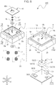
- Fig. 3 is an exploded perspective view of the input unit TP1 according to the first embodiment of the present invention
- Fig. 4 is a structural diagram illustrating the input unit TP1 according to the first embodiment of the present invention, the diagram being a cross sectional view along line IV-IV indicated in Fig. 2(b) .
- the input unit TP1 uses a so-called touch pad that can detect the coordinate position of the specific body region F99 (referred to be below as the fingertip), which is the user's finger tip.
- This input unit TP1 (touch pad) is of a detection method type called a capacitive type.
- the input unit TP1 is configured so that when the user brings the user's fingertip close to or into contact with the manipulation surface TPp, the input unit TP1 detects the coordinate position, on the manipulation surface TPp, of the fingertip according to a change in a capacitance value and outputs input information matching the coordinate position of the fingertip.
- the input unit TP1 is connected to the vibration generating device VB3. Specifically, the input unit TP1 is placed on a vibration transmitting member 5, which will be specifically described later, included in the vibration generating device VB3 (see Fig. 1 ). When the user performs an input manipulation, vibration is imparted from the vibration generating device VB3 to the input unit TP1.
- the input unit TP1 is shaped like a sheet as a whole.
- the input unit TP1 is structured by having an insulating board 51 made of an epoxy resin including a glass filler, an X-coordinate detection layer 11 laminated on one surface (on the same side as the Z1 direction indicated in Fig. 3 ) of the insulating board 51, a Y-coordinate detection layer 21 laminated on the other surface (on the same side as the Z2 direction indicated in Fig.
- a top cover 71 that covers the X-coordinate detection layer 11, and a capacitance detecting part 91 (see Fig. 6 ), not illustrated in Fig. 3 and Fig. 4 , that detects capacitances in the X-coordinate detection layer 11 and Y-coordinate detection layer 21.
- the insulating board 51, X-coordinate detection layer 11, and Y-coordinate detection layer 21 of the input unit TP1 are manufactured by using a so-called double-sided printed wiring board (PWB). That is, a copper foil on one surface of the double-sided printed wiring board (PWB) is patterned to form the X-coordinate detection layer 11, and a copper foil on the other surface is patterned to form the Y-coordinate detection layer 21.
- the X-coordinate detection layer 11 and Y-coordinate detection layer 21 cooperate with each other to perform detection of coordinates at which a fingertip is positioned.
- first electrodes in a strip shape are placed on the X-coordinate detection layer 11 of the input unit TP1. These first electrodes are placed in an equal distribution and form a first detection electrode group. A plurality of first electrodes in the first detection electrode group are arranged and linked in one row in the Y direction. First detection electrode rows are placed in the X direction in a distributed manner so as to be equally spaced. Therefore, it is possible to detect the fingertip's X coordinate on the manipulation surface TPp, according to detection data indicating that a first electrode in which row interacts with the user's fingertip.
- second electrodes in a strip shape are placed on the Y-coordinate detection layer 21 of the input unit TP1 as with the X-coordinate detection layer 11. These second electrodes are placed in an equal distribution and form a second detection electrode group. A plurality of second electrodes in the second detection electrode group are arranged and linked in one row in the X direction. Second detection electrode rows are placed in the Y direction in a distributed manner so as to be equally spaced. Therefore, it is possible to detect the fingertip's Y coordinate on the manipulation surface TPp, according to detection data indicating that a second electrode in which row interacts with the user's fingertip.
- the capacitance value between the first electrode and the second electrode changes in the vicinity of the fingertip, so the coordinate position of the fingertip can be detected according to this change in the capacitance value.
- the top cover 71 of the input unit TP1 is composed of a cover sheet 71C having the manipulation surface TPp, to which the user's fingertip is brought close or with which it is brought into contact, and a cover frame 71W, in an elongated frame shape, that covers the outer circumferential edge of the cover sheet 71C.
- the cover sheet 71C is manufactured from a polyethylene terephthalate (PET) sheet, which is a general film base material, and the cover frame 71W is manufactured by injecting an ABS resin (acrylonitrile butadiene styrene copolymer).
- PET polyethylene terephthalate
- ABS resin acrylonitrile butadiene styrene copolymer
- the capacitance detecting part 91 in the input unit TP1 is mounted on a wiring board 90 (see Fig. 6 ), which will be described later, has an integrated circuit having a capacitance detection circuit, and detects capacitances between the X-coordinate detection layer 11 and Y-coordinate detection layer 21 and a finger (specific body region F99). Moreover, the capacitance detecting part 91 has a control unit having a control circuit in an integrated circuit, and outputs detection results of the detected capacitances to an external unit. Incidentally, connections between the X-coordinate detection layer 11 and Y-coordinate detection layer 21 and the capacitance detecting part 91 are performed with flexible printed circuits (FPC), which are not illustrated.
- FPC flexible printed circuits
- Fig. 5 is a perspective view of the vibration generating device VB3 in the first embodiment of the present invention.
- Fig. 6 is an exploded perspective view of the vibration generating device VB3.
- Fig. 7 is a longitudinal cross-sectional view of the vibration generating device VB3 along line VII-VII indicated in Fig. 5 .
- the cross-section, indicated in Fig. 7 of a vibrating body 13 in a vibration generating member 3 is indicated in a simplified form.
- a detailed cross-section of the vibrating body 13 will be indicated in Fig. 8 described later.
- the vibration generating device VB3 has a box-like outside shape as indicated in Fig. 5 .
- the vibration generating device VB3 is composed of the vibration generating member 3 that has a movable part 13J operable in a vibration direction VD (Z direction indicated in Fig. 5 ), a base body 4 that holds the vibration generating member 3, and the vibration transmitting member 5 connected to the movable part 13J.
- the vibration generating device VB3 has urging members 7 (see Fig.
- the vibration generating device VB3 can drive the vibration generating member 3 in response to a touch manipulation to the input unit TP1 by the user, and can transmit (impart) vibration to the user.
- the vibration generating device VB3 can give a manipulation sense, that is, a vibration feedback feeling, to the user.
- Fig. 8 is a schematic diagram illustrating the vibration generating member 3;
- Fig. 8(a) is a cross-sectional view of the vibrating body 13 indicated in Fig. 7
- Fig. 8(b) is an enlarged view of a portion R indicated in Fig. 8(a) .
- Fig. 9 is a schematic diagram illustrating the vibrating body 13 in the vibration generating member 3;
- Fig. 9(a) is a top view indicating a first yoke 13A and a second yoke 13B in the vibrating body 13,
- Fig. 9(b) is a side view of the first yoke 13A and second yoke 13B as viewed from the Y2 side indicated in Fig. 9(a) .
- the vibration generating member 3 is structured by having the vibrating body 13 that has the movable part 13J operable in the vibration direction VD, a control unit 33 that controls the vibrating body 13, and flexible printed circuits (FPC) (not illustrated) that electrically connect the vibrating body 13 and control unit 33.
- FPC flexible printed circuits
- the vibrating body 13 in the vibration generating member 3 is structured by having the movable part 13J operable in the vibration direction VD (X direction indicated in Fig. 5 ), the first yoke 13A and second yoke 13B, which are placed so as to be spaced in the vibration direction VD, a coil 13C placed in the vicinity of the first yoke 13A, and support bodies 13S (in Fig. 8 , spring members 13f and support plates 13g) that support the first yoke 13A so as to be movable in the vibration direction VD.
- the vibrating body 13 has a main body case 13K that is in a cylindrical shape and accommodates the first yoke 13A, second yoke 13B, coil 13C, and the like as indicated in Fig. 6 , and also has a main body cover 13L that covers the lower side (on the same side as the Z2 direction indicated in Fig. 8 ) of the main body case 13K as indicated in Fig. 8(a) .
- a current is supplied to the coil 13C, magnetic paths are formed in the first yoke 13A and second yoke 13B and a magnetic attractive force is generated between the first yoke 13A and the second yoke 13B.
- the movable part 13J of the vibrating body 13 is manufactured from a metal material such as iron, and is placed so as to pass through the central portion of the main body case 13K as indicated in Fig. 6 .
- the movable part 13J moves so as to be able to reciprocate along the vibration direction VD in response to a driving signal applied to the vibrating body 13.
- Lhe movable part 13J can reciprocate in the pressing direction PD (matching the vibration direction VD) in response to a pressing manipulation by the user as well.
- the upper side (Z1 side indicated in Fig. 7 ) of the movable part 13J is fixed to the top surface 15t of the vibration transmitting member 5 by a first holding plate 16 and a second holding plate 26, which will be described later, connecting the movable part 13J to the vibration transmitting member 5.
- the operation of the movable part 13J in the vibration direction VD is transmitted to the vibration transmitting member 5.
- the first yoke 13A of the vibrating body 13 is manufactured from a soft magnetic material such as iron.
- the first yoke 13A has a first flat plate part 13a in a ring shape, its outside shape being circular in a plan view, its central portion being a circular opening, and also has a second flat plate part 13b in a ring shape, which is formed outside the first flat plate part 13a.
- the first yoke 13A has an inner wall part 13w extending perpendicularly from the inner end of the second flat plate part 13b (in Fig.
- the inner wall part 13w extends in the Z1 direction), and also has an outer wall part 13x extending perpendicularly from the outer end of the second flat plate part 13b.
- the first yoke 13A forms a U-shaped cross section with the second flat plate part 13b, inner wall part 13w, and outer wall part 13x.
- the first yoke 13A is fixed to the support plate 13g of the support body 13S.
- This support plate 13g is supported to the main body case 13K by the spring member 13f of the support body 13S so as to be movable.
- the movement of the first yoke 13A in the vibration direction VD becomes possible.
- the support plate 13g is engaged with the movable part 13J, so the movement of the first yoke 13A in the vibration direction VD is transmitted through the support plate 13g to the movable part 13J.
- these parts include the spring members 13f, support plates 13g, and main body case 13K.
- the second yoke 13B of the vibrating body 13 is manufactured from a soft magnetic material such as iron, as with the first yoke 13A.
- the second yoke 13B has a flat plate part 13e in a ring shape, its outside shape being circular in a plan view, its central portion being a circular opening.
- the second yoke 13B has an outer wall part 13z extending perpendicularly from the outer end of the flat plate part 13e.
- the second yoke 13B forms an L-shaped cross section with the flat plate part 13e and outer wall part 13z.
- the second yoke 13B is fixed to the main body cover 13L.
- the first yoke 13A and second yoke 13B are placed so that they are spaced and face each other in the vibration direction VD and that the outer wall part 13x of the first yoke 13A and the outer wall part 13z of the second yoke 13B face each other and the first flat plate part 13a of the first yoke 13A and the flat plate part 13e (this portion will be referred to be as the opposite flat plate part 13t) of the second yoke 13B face each other, as indicated in Fig. 8 and Fig. 9(b) .
- first yoke 13A and second yoke 13B are formed so that the size of the outside shape of the second yoke 13B is larger than the size of the outside shape of the first yoke 13A.
- first flat plate part 13a, inner wall part 13w, and outer wall part 13x of the first yoke 13A are accommodated in the storage part formed by the flat plate part 13e and outer wall part 13z of the second yoke 13B.
- the first yoke 13A and second yoke 13B are placed so that their central positions match.
- the outside shapes of the first yoke 13A and second yoke 13B are circular in a plan view. Therefore, even if their mutual positional relationship is slightly deviated from a desired positional relationship due to tolerances in part manufacturing and the like, deviation in a particular direction is lessened, so vibration with less eccentricity can be obtained.
- the first flat plate part 13a of the first yoke 13A has a first vibration-side opposite surface 13p, which faces the opposite flat plate part 13t of the second yoke 13B in the vibration direction VD
- the opposite flat plate part 13t of the second yoke 13B has a second vibration-side opposite surface 13q, which faces the first vibration-side opposite surface 13p.
- the outer wall part 13x of the first yoke 13A has a first orthogonal-side opposite surface 13r, which faces the outer wall part 13z of the second yoke 13B in the orthogonal direction HD
- the outer wall part 13z of the second yoke 13B has a second orthogonal-side opposite surface 13s, which faces the first orthogonal-side opposite surface 13r.
- a first gap GP1 is generated between the first vibration-side opposite surface 13p of the first yoke 13A and the second vibration-side opposite surface 13q of the second yoke 13B
- a second gap GP2 is generated between the first orthogonal-side opposite surface 13r of the first yoke 13A and the second orthogonal-side opposite surface 13s of the second yoke 13B.
- This first gap GP1 is formed so as to be narrower than the second gap GP2.
- the first yoke 13A moves faster to the same side as the second yoke 13B in the vibration direction VD in the first gap GP1, so the first yoke 13A vibrates in the vibration direction VD. Accordingly, it is possible for the vibration transmitting member 5 to give stronger vibration in the vibration direction VD to the input unit TP1 through the movable part 13J, which is operable in the vibration direction VD.
- the first vibration-side opposite surface 13p and second vibration-side opposite surface 13q are formed with such areas that any one of the first vibration-side opposite surface 13p and second vibration-side opposite surface 13q covers the other. Therefore, even when the first yoke 13A moves in the vibration direction VD when a magnetic attractive force is generated, the first vibration-side opposite surface 13p and second vibration-side opposite surface 13q surely overlap, so a stable magnetic attractive force can be obtained.
- the first gap GP1 is provided over the entire circumference in the vibration direction VD, so a stronger magnetic attractive force between the first yoke 13A and the second yoke 13B can be obtained in a stable manner.
- a stronger magnetic attractive force between the first yoke 13A and the second yoke 13B can be obtained in a stable manner.
- an arrangement is made so that, for the first orthogonal-side opposite surface 13r of the outer wall part 13x and the second orthogonal-side opposite surface 13s of the outer wall part 13z, which are formed in the initial state in which no magnetic attractive force is generated, the outer wall part 13x, of the first yoke 13A, that is not opposite to the outer wall part 13z is formed in a direction (Z1 direction indicated in Fig. 8 ) opposite to the direction (Z2 direction indicated in Fig. 8 ) in which the first yoke 13A moves and the outer wall part 13z, of the second yoke 13B, that is not opposite to the outer wall part 13x is formed in the direction in which the first yoke 13A moves.
- the outer wall part 13x (on the same side as the end of the second flat plate part 13b) that is not opposite to the outer wall part 13z of the second yoke 13B in the initial state becomes opposite to the outer wall part 13z of the second yoke 13B
- the outer wall part 13z (on the same side as the end of the flat plate part 13e) that is not opposite to the outer wall part 13x of the first yoke 13A in the initial state becomes opposite to the outer wall part 13x of the first yoke 13A.
- the opposite areas of the first orthogonal-side opposite surface 13r and the second orthogonal-side opposite surface 13s are increased. Therefore, the area of a portion that has an effect of mainly inducing a magnetic flux is increased, so the magnetic resistance in this portion is reduced in contrary to the fact that the opposite areas of the second fixed iron core 914 and magnetic flux inducing part 932 are reduced and the magnetic resistance is thereby increased as in the conventional example.
- the magnetic attractive force between the first yoke 13A and the second yoke 13B in the first gap GP1 becomes even stronger, making it possible to give even stronger vibration.
- control unit 33 in the vibration generating member 3 uses an integrated circuit (IC) and is mounted on the wiring board 90 as indicated in Fig. 6 .
- the control unit 33 transmits a driving signal to the vibrating body 13 on the basis of a command signal according to the input manipulation on the input unit TP1 connected to the vibration generating device VB3.
- the flexible printed circuits (FPC) in the vibration generating member 3 uses a film base material, based on a polyimide (PI) resin, which is generally in widespread use.
- One end of the FPC is connected to the vibrating body 13, and the other end is connected to the control unit 33 through a connector CN indicated in Fig. 6 .
- the base body 4 in the vibration generating device VB3 will be described.
- the base body 4 is manufactured by injecting a synthetic resin such as an ABS (acrylonitrile butadiene styrene copolymer) resin.
- a synthetic resin such as an ABS (acrylonitrile butadiene styrene copolymer) resin.
- the base body 4 is composed of a base part 14 in a box shape, the base part 14 being open on the lower side (on the same side as the Z2 direction indicated in Fig. 6 ) (see Fig. 7 ), and outer circumferential wall parts 24, which are connected to the base part 14 on the lower side (see Fig. 7 ) and enclose the outer circumference.
- the base part 14 in the base body 4 is composed of an upper wall part 14t in a substantially square shape, side wall parts 14w extending downward from the four edges of the upper wall part 14t, and linkage parts 14r (see Fig. 7 ) that link the base part 14 and outer circumferential wall parts 24 together.
- the side wall parts 14w of the base part 14 and the outer circumferential wall parts 24 form groove parts 4m.
- the upper wall part 14t of the base part 14 is provided with a circular through-hole 14h at the central portion and with three protrusions 14s extending upward from the upper wall part 14t.
- the movable part 13J of the vibration generating member 3 is inserted into this circular through-hole 14h and, although not illustrated in detail, the main body case 13K of the vibrating body 13 is accommodated in an accommodating part 14c inside the base part 14, as indicated in Fig. 7 .
- the main body case 13K of the vibrating body 13 is fixed to the inside of the upper wall part 14t with screws or the like, and the vibration generating member 3 is held by the base body 4.
- the urging members 7 are placed on the upper wall part 14t.
- the top plate member 40 in the vibration generating device VB3 will be described.
- the top plate member 40 is manufactured in a rectangular plate shape by injecting a synthetic resin such as an ABS resin.
- the top plate member 40 has a circular through-hole 40h at the central portion as indicated in Fig. 6 , and also has restricting parts 40t protruding downward from the lower surface at positions at which they enclose the through-hole 40h as indicated in Fig. 7 .
- the lower surface of the top plate member 40 and the protrusions 14s of the base body 4 are bonded or welded together and the top plate member 40 is integrally fixed to the base body 4.
- the vibration transmitting member 5 in the vibration generating device VB3 will be described.
- the vibration transmitting member 5 is manufactured by injecting a synthetic resin such as an ABS resin.
- the vibration transmitting member 5 is composed of a base part 15 in a box shape, which is open on the lower side (see Fig. 7 ), and a placement part 25, which is formed along the outer circumference of the upper surface side of the base part 15 and protrudes upward.
- the base part 15 in the vibration transmitting member 5 is composed of a top surface 15t in a substantially square shape and side walls 15w extending downward from the four edges of the top surface 15t.
- the side walls 15w of the base part 15 are inserted into the groove parts 4m in the base body 4 and the vibration transmitting member 5 is disposed with space enough for it to be movable in vibration direction VD.
- a first hole part 15h which is circular, is formed at the central portion and three second hole parts 15k are formed at positions corresponding to the protrusions 14s of the base body 4.
- the movable part 13J in the vibration generating member 3 is inserted into the first hole part 15h and the protrusions 14s of the base part 14 in the base body 4 are inserted into the second hole parts 15k.
- the top surface 15t is sandwiched by the first holding plate 16 and second holding plate 26 and is tightened with a nut NT. Therefore, the vibration transmitting member 5 and movable part 13J are connected together and are fixed. Thus, the operation of the movable part 13J in the vibration direction VD is transmitted to the vibration transmitting member 5.
- the placement part 25 in the vibration transmitting member 5 extends upward from the upper surface side of the base part 15 and is formed in a frame shape along the outer circumference of the base part 15.
- the input unit TP1 is placed on this placement part 25 and is fixed to it as indicated in Fig. 1 .
- the vibration generating device VB3 described above when a manipulation is performed to the manipulation surface TPp of the input unit TP1 with the specific body region F99 such as a user's fingertip, strong vibration is given to the input unit TP1. Therefore, it is possible to provide the manipulation feeling imparting input device 101 with which a stronger manipulation feeling is imparted without supplying much more current to the coil 13C to generate a large magnetic field.
- the input unit TP1 is connected integrally to the placement part 25
- vibration generated by the vibration generating device VB3 is efficiently transmitted directly to the input unit TP1. Therefore, even when the volumes of the first yoke 13A and second yoke 13B are reduced or the coil 13C is downsized, vibration generated by the vibration generating device VB3 is efficiently transmitted to the input unit TP1, so it is possible to downsize the vibration generating device VB3 without a manipulation feeling being impaired.
- the urging members 7 are composed by using four general coil springs. As indicated in Fig. 7 , the urging members 7 are placed between the upper wall part 14t of the base body 4 and the top surface 15t of the vibration transmitting member 5, and urge the vibration generating member 3 and vibration transmitting member 5 in directions away from each other. Moreover, since a coil spring is used as the urging member 7, the urging member 7 can be deformed in the vibration direction VD (Z direction indicated in Fig. 6 ). This allows the vibration transmitting member 5 to move in the vibration direction VD. Incidentally, the urging member 7 is not limited to a coil spring; for example, magnets may be used.
- the wiring board 90 in the vibration generating device VB3 will be described.
- a generally-used double-sided wiring type of printed wiring board (PWB) is used as the wiring board 90.
- the wiring board 90 is accommodated in the accommodating part 14c inside the base part 14.
- the wiring board 90 is fixed to the base body 4 with screws or the like.
- the control unit 33 in the vibration generating member 3, the capacitance detecting part 91 in the input unit TP1, the connector CN, and the like are mounted on the wiring board 90.
- the first gap GP1 between the first vibration-side opposite surface 13p and the second vibration-side opposite surface 13q, the first gap GP1 being formed in the vibration direction VD between the first yoke 13A and second yoke 13B of the vibration generating member 3, is narrower than the second gap GP2 between the first orthogonal-side opposite surface 13r and the second orthogonal-side opposite surface 13s, the second gap GP2 being formed in the orthogonal direction HD between the first yoke 13A and the second yoke 13B.
- the vibration transmitting member 5 to give stronger vibration in the vibration direction VD through the movable part 13J, which is operable in the vibration direction VD. Therefore, it is possible to provide the vibration generating device VB3 that can give a stronger manipulation feeling without supplying much more current to the coil 13C to generate a large magnetic field.
- the opposite areas of the first orthogonal-side opposite surface 13r and second orthogonal-side opposite surface 13s in the second gap GP2, which has a wider gap than the first gap GP1, are larger than the opposite areas of the first vibration-side opposite surface 13p and second vibration-side opposite surface 13q in the first gap GP1.
- the opposite areas of the first orthogonal-side opposite surface 13r and the second orthogonal-side opposite surface 13s are increased, so the area of a portion that has an effect of mainly inducing a magnetic flux is increased. Therefore, the magnetic resistance in this portion is reduced in contrary to the fact that the opposite areas of the second fixed iron core 914 and magnetic flux inducing part 932 are reduced and the magnetic resistance is thereby increased as in the conventional example.
- the magnetic attractive force between the first yoke 13A and the second yoke 13B in the first gap GP1 becomes even stronger, making it possible to give even stronger vibration.
- the manipulation feeling imparting input device 101 in the first embodiment of the present invention uses the vibration generating device VB3 described in any portion in the above description, when a manipulation is performed to the manipulation surface TPp of the input unit TP1 with the specific body region F99 such as a user's fingertip, strong vibration is given to the input unit TP1. Therefore, it is possible to provide the manipulation feeling imparting input device 101 with which a stronger manipulation feeling is imparted without supplying much more current to the coil 13C to generate a large magnetic field.
- the input unit TP1 is connected integrally to the vibration transmitting member 5 in the vibration generating device VB3, vibration generated by the vibration generating device VB3 is efficiently transmitted directly to the input unit TP1.
- an even stronger manipulation feeling is imparted to the input unit TP1.
- the present invention is not limited to the embodiment described above.
- the present invention can also be practiced by, for example, making variations as described below. These forms of practice are also included in the technical range of the present invention.
- the spring member 13f is used as the support body 13S that supports the first yoke 13A so as to be movable in the vibration direction VD
- an arrangement in which the spring member 13f is not used may be made.
- the urging member 7 that allows the movement of the movable part 13J in the vibration direction VD through the vibration transmitting member 5 undertakes a function as a support body that supports the movement of the first yoke 13A engaged with the movable part 13J in the vibration direction VD.
- a capacitive touch pad as the input unit TP1
- a so-called touch panel that uses a translucent base material and translucent electrodes may be used.
- a panel of a type that uses conductive-filler-bearing conductive patterns may be used as electrodes.
- an arrangement has been preferably made by making the outside shapes of the first yoke 13A and second yoke 13B circular in a plan view
- this is not a limitation.
- an arrangement may be made so that the outside shapes are rectangular in a plan view.
- an arrangement may be made in which the first yoke 13A and second yoke 13B are provided independently of each other in the vibration direction VD.
- the X-coordinate detection layer 11, Y-coordinate detection layer 21, and insulating board 51 have been preferably manufactured by using a double-sided printed wiring board (PWB), this is not a limitation. They may be manufactured by, for example, printing a conductive paste on both surfaces of a film base material and curing the paste or may be manufactured by, for example, creating a transparent conductive film (for example, ITO (tin-doped indium oxide)) on both surfaces of a glass base material.
- PWB double-sided printed wiring board
- an arrangement may be made in which a detection member that detects a pressing operation to the input unit TP1.
- a detection member that detects a pressing operation to the input unit TP1.
- a switch member such as a push switch or a sensor member such a pressure sensor or force sensor may be used and placed in the vicinity of the movable part 13J.
- the present invention is not limited to the embodiment described above.
- the present invention can be appropriately modified unless the range of the object of the present invention is deviated.
Description
- The present invention relates to a vibration generating device used in various types of electronic units and to an input device that uses the vibration generating device.
- In the electronic unit field, input devices such as touch panels and touch pads have been frequently used in recent years. This input device is such that when a manipulator (user) brings a fingertip into contact with the manipulation surface, the input device detects the coordinate position of the fingertip on the manipulation surface according to a change in a capacitance value or the like and enables an input manipulation matching the coordinate position. For example, this type of input device is installed on the front surface of a display device such as an LCD (liquid crystal display). When the user places a fingertip on a desired manipulation area displayed on the screen of the display device, manipulation contents of the manipulation area are executed.
- Incidentally, with this type of input device, when the user manipulates the input device by bringing the user's fingertip into contact with the manipulation surface, a difference in sense transmitted to the fingertip does not occur between before and after the manipulation (input), so the user has not been able to obtain a manipulation sense (manipulation feeling). Therefore, a feeling stimulus generating device that gives a feeling stimulus (feeling feedback) to the user's fingertip has been conventionally proposed, and there has been a case in which an input device is used in combination with this feeling stimulus generating device. As a typical example of this feeling stimulus generating device, a type of stimulus generating device that gives vibration to impart a feeling stimulus is most used.
- As this vibration type of feeling stimulus generating device, an
electromagnetic actuator 900 as indicated inFig. 10 andFig. 11 is proposed inPTL 1.Fig. 10 is a drawing illustrating theelectromagnetic actuator 900 in a conventional example.Fig. 10(a) is a longitudinal cross-sectional view that schematically indicates it, andFig. 10(b) is a structural diagram on which the main constituent components (actuator portion) of a portion P indicated inFig. 10(a) are extracted.Fig. 11 is magnetic path analysis results indicating the effect of the actuator portion indicated inFig. 10(b) ;Fig. 11(a) is a magnetic flux line diagram in an initial state, andFig. 11(b) is a magnetic flux line diagram in a state in which a current is supplied to acoil 918. - The
electromagnetic actuator 900 indicated inFig. 10 has: a first fixediron core 912 and a second fixediron core 914, which are disposed opposite to each other through a predetermined gap in the direction of an axial line O; amovable iron core 916 disposed so as to be movable along the axial line O in the vicinity of this gap; and acoil 918 that exerts magnetic fields around the two fixed iron cores (first fixediron core 912 and second fixed iron core 914) and themovable iron core 916, forms magnetic paths in them, and moves themovable iron core 916 along the axial line O. Basically, each of these members is formed in a rotationally symmetrical form, that is, in a circular form, and is accommodated in acylindrical housing 920. - With the
electromagnetic actuator 900, when a current is supplied to thecoil 918 from an initial state indicated inFig. 11(a) , a magnetic attractive force is generated for themovable iron core 916 from each of the two fixed iron cores (first fixediron core 912 and second fixed iron core 914). At this time, the second fixediron core 914 and a magneticflux inducing part 934, extending in the direction of the axial line O, of themovable iron core 916 mainly undertake an effect of inducing a magnetic flux, and the first fixediron core 912 and a magneticflux action part 932, extending in a direction crossing the axial line O, of themovable iron core 916 mainly undertake an attraction effect. Due to this, the magnetic attractive force on the same side as the first fixediron core 912 is larger than the magnetic attractive force on the same side as the second fixediron core 914. Therefore, when a current is supplied, themovable iron core 916 moves toward the first fixediron core 912 and enters a state indicated inFig. 11(b) . Due to the movement of themovable iron core 916 at this time, vibration is generated. - PTL 1:
WO2012/067178 - In the conventional example, however, in the initial state in which no magnetic attractive force is generated, a gap between the second
fixed iron core 914 and the magneticflux inducing part 934, in which it is desirable to suppress a magnetic attractive force, is narrower than a gap between the firstfixed iron core 912 and the magneticflux action part 932, in which it is desirable to generate a magnetic attractive force. Therefore, the arrangement is not such that a strong magnetic attractive force is generated between the first fixediron core 912 and themovable iron core 916. Furthermore, when a current is supplied and themovable iron core 916 moves toward the first fixediron core 912, the opposite areas of the second fixediron core 914 and magneticflux inducing part 934 are reduced and the magnetic resistance is increased. Therefore, the magnetic attractive force between the first fixediron core 912 andmovable iron core 916 is reduced according to an amount by which the magnetic resistance is increased. - Due to this, in the conventional example, there has been the problem that unless much more current is supplied to the
coil 918 to generate a large magnetic field, themovable iron core 916 cannot be moved faster and stronger vibration cannot thereby be obtained. On the other hand, in the arrangement as in the conventional example, if much more current is supplied to thecoil 918 to generate a large magnetic filed, attraction between the second fixediron core 914 and the magneticflux inducing part 934 is increased and vibration in an undesired direction is generated. In some cases, there has been the risk that an abutting sound (contact noise) is generated due to a contact between the second fixediron core 914 and themovable iron core 916. -
US 2009/079595 A1 discloses a rotary operation type input device to be mounted on various electronic appliances and having an input operation unit for searching or entering various electronic data.WO 2015/064038 A1 discloses an input device that reduces a size of each of magnetic-pole formation sections such as magnets and ensures the magnitude of an operation reaction force that can be generated.US 6,286,671 B1 discloses a vibration generation apparatus which allows vibration frequency and amplitude to be independently controlled and to produce various modes of vibration involving shocks in addition to simple modes of vibration.EP 3324275 A1 discloses a manipulation feeling imparting input device configured so that a vibration sound is suppressed in a flat-type input unit to which an operational feeling based on vibration is imparted. - The present invention addresses the problem described above with the object of providing a vibration generating device that gives a stronger manipulation feeling and a vibration generating device that uses the vibration generating device.
- To solve this problem, a vibration generating device and a manipulation feeling input device according to the independent claims are proposed. Preferred embodiments are provided by the dependent claims. The embodiments and/or examples of the following description which are not covered by the claims, are provided for illustrative purpose only and are only intended to assist the reader in understanding the present invention. However, such embodiments and/or examples which are not covered by the claims do not form part of the present invention that is solely defined by the claims.
- According to this, with the vibration generating device in the present invention, when a current is supplied to the coil, a magnetic attractive force between the first yoke and the second yoke in the first gap becomes strong. Therefore, the first yoke moves faster to the same side as the second yoke in the vibration direction in the first gap, so the first yoke vibrates in the vibration direction. Accordingly, it is possible for the vibration transmitting member to give stronger vibration in the vibration direction through the movable part, which is operable in the vibration direction. Therefore, it is possible to provide a vibration generating device that can give a stronger manipulation feeling without supplying much more current to the coil to generate a large magnetic field.
- Moreover, the vibration generating device in the present invention is characterized in that, in an initial state in which no magnetic attractive force is generated, the opposite areas of the first orthogonal-side opposite surface and second orthogonal-side opposite surface are larger than the opposite areas of the first vibration-side opposite surface and second vibration-side opposite surface.
- According to this, when a current is supplied to the coil, a magnetic resistance (the ease with which a magnetic flux flows) caused in the second gap in the magnetic circuit formed from the first yoke and second yoke can be reduced. Therefore, a magnetic resistance in the entire magnetic circuit can be reduced and the magnetic attractive force between the first yoke and the second yoke in the vibration direction (in the first gap) can thereby be made stronger. Thus, the first yoke moves even faster to the same side as the second yoke in the vibration direction. Therefore, it is possible for the vibration transmitting member to give even stronger vibration in the vibration direction through the movable part, which is operable in the vibration direction.
- Moreover, the vibration generating device in the present invention is characterized in that when a magnetic attractive force is generated, the opposite areas of the first orthogonal-side opposite surface and the second orthogonal-side opposite surface are increased.
- According to this, the area of a portion that has an effect of mainly inducing a magnetic flux is increased. Therefore, the magnetic resistance in this portion is reduced in contrary to the fact that the opposite areas of the second fixed
iron core 914 and magneticflux inducing part 932 are reduced and the magnetic resistance is thereby increased as in the conventional example. Thus, the magnetic attractive force between the first yoke and the second yoke in the first gap becomes even stronger, making it possible to give even stronger vibration. - A manipulation feeling imparting input device in the present invention is characterized by having the vibration generating device described in any portion in the above description and an input unit connected to the vibration transmitting member in the vibration generating device, the input unit being manipulated by a specific body region such as a user's fingertip. The manipulation feeling imparting input device is also characterized in that the input unit has a manipulation surface that is manipulated and a control unit that processes input information manipulated on the manipulation surface and makes an output and that when the manipulation surface is manipulated, vibration is imparted to the input unit.
- According to this, when a manipulation is performed to the manipulation surface of the input unit, strong vibration is given to the input unit. Therefore, it is possible to provide the manipulation feeling imparting input device with which a stronger manipulation feeling is imparted without supplying much more current to the coil to generate a large magnetic field.
- Moreover, the manipulation feeling imparting input device in the present invention is characterized in that the input unit is connected integrally to the vibration transmitting member.
- According to this, vibration generated by the vibration generating device is efficiently transmitted directly to the input unit. Thus, an even stronger manipulation feeling is imparted.
- With the vibration generating device in the present invention, when a current is supplied to the coil, a magnetic attractive force between the first yoke and the second yoke in the first gap becomes strong. Therefore, the first yoke moves faster to the same side as the second yoke in the vibration direction in the first gap, so the first yoke vibrates in the vibration direction. Accordingly, it is possible for the vibration transmitting member to give stronger vibration in the vibration direction through the movable part, which is operable in the vibration direction. Therefore, it is possible to provide a vibration generating device that can give a stronger manipulation feeling without supplying much more current to the coil to generate a large magnetic field.
- The manipulation feeling imparting input device in the present invention can give strong vibration to an input unit when a manipulation is performed to the manipulation surface of the input unit. Therefore, it is possible to provide a manipulation feeling imparting input device with which a stronger manipulation feeling is imparted without supplying much more current to the coil to generate a large magnetic field.
-
- [
Fig. 1] Fig. 1 is a side-surface structural diagram illustrating a manipulation feeling imparting input device in a first embodiment of the present invention. - [
Fig. 2] Fig. 2 is a structural diagram illustrating an input unit included in the manipulation feeling imparting input device according to the first embodiment of the present invention;Fig. 2(a) is a perspective view of the input unit, andFig. 2(b) is a top view as viewed from the Z1 side indicated inFig. 2(a) . - [
Fig. 3] Fig. 3 is an exploded perspective view of the input unit according to the first embodiment of the present invention. - [
Fig. 4] Fig. 4 is a structural diagram illustrating the input unit according to the first embodiment of the present invention, the diagram being a cross sectional view along line IV-IV indicated inFig. 2(b) . - [
Fig. 5] Fig. 5 is a perspective view of a vibration generating device in the manipulation feeling imparting input device according to the first embodiment of the present invention. - [
Fig. 6] Fig. 6 is an exploded perspective view of the vibration generating device according to the first embodiment of the present invention. - [
Fig. 7] Fig. 7 is a drawing illustrating the vibration generating device according to the first embodiment of the present invention, the drawing being a longitudinal cross-sectional view along line VII-VII indicated inFig. 5 . - [
Fig. 8] Fig. 8 is a schematic diagram illustrating a vibration generating member in the vibration generating device according to the first embodiment of the present invention;Fig. 8(a) is a longitudinal cross-sectional view of a vibrating body included in the vibration generating member indicated inFig. 7 , andFig. 8(b) is an enlarged view of a portion R indicated inFig. 8(a) . - [
Fig. 9] Fig. 9 is a schematic diagram illustrating the vibration generating member in the vibration generating device according to the first embodiment of the present invention;Fig. 9(a) is a top view indicating a first yoke and a second yoke in the vibrating body in the vibration generating member, andFig. 9(b) is a side view of the first yoke and second yoke as viewed from the Y2 side indicated inFig. 9(a) . - [
Fig. 10] Fig. 10 is a drawing illustrating an electromagnetic actuator in a conventional example;Fig. 10(a) is a longitudinal cross-sectional view that schematically indicates the electromagnetic actuator, andFig. 10(b) is a structural diagram on which the main constituent components (actuator portion) of a portion P indicated inFig. 10(a) are extracted. - [
Fig. 11] Fig. 11 is magnetic path analysis results indicating the effect of the actuator portion in the magnetic actuator in the conventional example;Fig. 11(a) is a magnetic flux line diagram in an initial state, andFig. 11(b) is a magnetic flux line diagram in a state in which a current is supplied to a coil. - An embodiment of the present invention will be described below with reference to the drawings.
- In the first embodiment of the present invention, a vibration generating device VB3 and a manipulation feeling imparting
input device 101 that uses the vibration generating device VB3 will be described. First, the manipulation feeling impartinginput device 101 will be described.Fig. 1 is a side-surface structural diagram illustrating the manipulation feeling impartinginput device 101 that uses the vibration generating device VB3 according to the first embodiment of the present invention. - As indicated in
Fig. 1 , the manipulation feeling impartinginput device 101 in the first embodiment of the present invention is composed of an input unit TP1 that has a manipulation surface TPp manipulated by a specific body region F99 such as a user's fingertip and the vibration generating device VB3 in the first embodiment of the present invention. The input unit TP1 is connected to the vibration generating device VB3, and vibration from the vibration generating device VB3 is imparted to the input unit TP1. - First, the input unit TP1 of the manipulation feeling imparting
input device 101 will be described.Fig. 2 is a structural diagram illustrating the input unit TP1 according to the first embodiment of the present invention;Fig. 2(a) is a perspective view of the input unit TP1, andFig. 2(b) is a top view as viewed from the Z1 side indicated inFig. 2(a) .Fig. 3 is an exploded perspective view of the input unit TP1 according to the first embodiment of the present invention.Fig. 4 is a structural diagram illustrating the input unit TP1 according to the first embodiment of the present invention, the diagram being a cross sectional view along line IV-IV indicated inFig. 2(b) . - The input unit TP1 uses a so-called touch pad that can detect the coordinate position of the specific body region F99 (referred to be below as the fingertip), which is the user's finger tip. This input unit TP1 (touch pad) is of a detection method type called a capacitive type. The input unit TP1 is configured so that when the user brings the user's fingertip close to or into contact with the manipulation surface TPp, the input unit TP1 detects the coordinate position, on the manipulation surface TPp, of the fingertip according to a change in a capacitance value and outputs input information matching the coordinate position of the fingertip.
- Moreover, the input unit TP1 is connected to the vibration generating device VB3. Specifically, the input unit TP1 is placed on a
vibration transmitting member 5, which will be specifically described later, included in the vibration generating device VB3 (seeFig. 1 ). When the user performs an input manipulation, vibration is imparted from the vibration generating device VB3 to the input unit TP1. - Next, the detailed structure of the input unit TP1 will be described. As indicated in
Fig. 2 , the input unit TP1 is shaped like a sheet as a whole. As indicated inFig. 3 andFig. 4 , the input unit TP1 is structured by having an insulatingboard 51 made of an epoxy resin including a glass filler, anX-coordinate detection layer 11 laminated on one surface (on the same side as the Z1 direction indicated inFig. 3 ) of the insulatingboard 51, a Y-coordinatedetection layer 21 laminated on the other surface (on the same side as the Z2 direction indicated inFig. 3 ) of the insulatingboard 51, atop cover 71 that covers theX-coordinate detection layer 11, and a capacitance detecting part 91 (seeFig. 6 ), not illustrated inFig. 3 andFig. 4 , that detects capacitances in theX-coordinate detection layer 11 and Y-coordinatedetection layer 21. - First, the insulating
board 51,X-coordinate detection layer 11, and Y-coordinatedetection layer 21 of the input unit TP1 are manufactured by using a so-called double-sided printed wiring board (PWB). That is, a copper foil on one surface of the double-sided printed wiring board (PWB) is patterned to form theX-coordinate detection layer 11, and a copper foil on the other surface is patterned to form the Y-coordinatedetection layer 21. TheX-coordinate detection layer 11 and Y-coordinatedetection layer 21 cooperate with each other to perform detection of coordinates at which a fingertip is positioned. - Although not illustrated in detail, many first electrodes in a strip shape are placed on the
X-coordinate detection layer 11 of the input unit TP1. These first electrodes are placed in an equal distribution and form a first detection electrode group. A plurality of first electrodes in the first detection electrode group are arranged and linked in one row in the Y direction. First detection electrode rows are placed in the X direction in a distributed manner so as to be equally spaced. Therefore, it is possible to detect the fingertip's X coordinate on the manipulation surface TPp, according to detection data indicating that a first electrode in which row interacts with the user's fingertip. - Moreover, many second electrodes in a strip shape are placed on the Y-coordinate
detection layer 21 of the input unit TP1 as with theX-coordinate detection layer 11. These second electrodes are placed in an equal distribution and form a second detection electrode group. A plurality of second electrodes in the second detection electrode group are arranged and linked in one row in the X direction. Second detection electrode rows are placed in the Y direction in a distributed manner so as to be equally spaced. Therefore, it is possible to detect the fingertip's Y coordinate on the manipulation surface TPp, according to detection data indicating that a second electrode in which row interacts with the user's fingertip. Incidentally, although detailed descriptions of the detection principle of the touch pad will be omitted because the principle is known, when the user uses a fingertip to make a proximity or contact, the capacitance value between the first electrode and the second electrode changes in the vicinity of the fingertip, so the coordinate position of the fingertip can be detected according to this change in the capacitance value. - Next, as indicated in
Fig. 3 , thetop cover 71 of the input unit TP1 is composed of acover sheet 71C having the manipulation surface TPp, to which the user's fingertip is brought close or with which it is brought into contact, and acover frame 71W, in an elongated frame shape, that covers the outer circumferential edge of thecover sheet 71C. Moreover, thecover sheet 71C is manufactured from a polyethylene terephthalate (PET) sheet, which is a general film base material, and thecover frame 71W is manufactured by injecting an ABS resin (acrylonitrile butadiene styrene copolymer). Thecover sheet 71C andcover frame 71W are bonded to each other with an adhesive such as a double-sided tape, and thetop cover 71 is bonded so as to cover theX-coordinate detection layer 11. - Next, the
capacitance detecting part 91 in the input unit TP1 is mounted on a wiring board 90 (seeFig. 6 ), which will be described later, has an integrated circuit having a capacitance detection circuit, and detects capacitances between theX-coordinate detection layer 11 and Y-coordinatedetection layer 21 and a finger (specific body region F99). Moreover, thecapacitance detecting part 91 has a control unit having a control circuit in an integrated circuit, and outputs detection results of the detected capacitances to an external unit. Incidentally, connections between theX-coordinate detection layer 11 and Y-coordinatedetection layer 21 and thecapacitance detecting part 91 are performed with flexible printed circuits (FPC), which are not illustrated. - Next, the vibration generating device VB3 in the first embodiment of the present invention, which is included in the manipulation feeling imparting
input device 101, will be described.Fig. 5 is a perspective view of the vibration generating device VB3 in the first embodiment of the present invention.Fig. 6 is an exploded perspective view of the vibration generating device VB3.Fig. 7 is a longitudinal cross-sectional view of the vibration generating device VB3 along line VII-VII indicated inFig. 5 . Incidentally, the cross-section, indicated inFig. 7 , of a vibratingbody 13 in avibration generating member 3 is indicated in a simplified form. A detailed cross-section of the vibratingbody 13 will be indicated inFig. 8 described later. - The vibration generating device VB3 has a box-like outside shape as indicated in
Fig. 5 . As indicated inFig. 6 andFig. 7 , the vibration generating device VB3 is composed of thevibration generating member 3 that has amovable part 13J operable in a vibration direction VD (Z direction indicated inFig. 5 ), abase body 4 that holds thevibration generating member 3, and thevibration transmitting member 5 connected to themovable part 13J. In addition, in the first embodiment of the present invention, the vibration generating device VB3 has urging members 7 (seeFig. 7 ) that urge thevibration generating member 3 andvibration transmitting member 5 in directions away from each other, atop plate member 40 fixed to thebase body 4, and thewiring board 90 on which thecapacitance detecting part 91 of the input unit TP1 is mounted, as indicated inFig. 6 . With the input unit TP1 placed on (connected to) thevibration transmitting member 5, the vibration generating device VB3 can drive thevibration generating member 3 in response to a touch manipulation to the input unit TP1 by the user, and can transmit (impart) vibration to the user. Thus, for a device with which it is difficult to obtain a manipulation sense, the vibration generating device VB3 can give a manipulation sense, that is, a vibration feedback feeling, to the user. - First, the
vibration generating member 3 in the vibration generating device VB3 will be described.Fig. 8 is a schematic diagram illustrating thevibration generating member 3;Fig. 8(a) is a cross-sectional view of the vibratingbody 13 indicated inFig. 7 , andFig. 8(b) is an enlarged view of a portion R indicated inFig. 8(a) .Fig. 9 is a schematic diagram illustrating the vibratingbody 13 in thevibration generating member 3;Fig. 9(a) is a top view indicating afirst yoke 13A and asecond yoke 13B in the vibratingbody 13, andFig. 9(b) is a side view of thefirst yoke 13A andsecond yoke 13B as viewed from the Y2 side indicated inFig. 9(a) . - As indicated in
Fig. 6 , thevibration generating member 3 is structured by having the vibratingbody 13 that has themovable part 13J operable in the vibration direction VD, acontrol unit 33 that controls the vibratingbody 13, and flexible printed circuits (FPC) (not illustrated) that electrically connect the vibratingbody 13 andcontrol unit 33. - First, as indicated in
Fig. 8 , the vibratingbody 13 in thevibration generating member 3 is structured by having themovable part 13J operable in the vibration direction VD (X direction indicated inFig. 5 ), thefirst yoke 13A andsecond yoke 13B, which are placed so as to be spaced in the vibration direction VD, acoil 13C placed in the vicinity of thefirst yoke 13A, andsupport bodies 13S (inFig. 8 ,spring members 13f andsupport plates 13g) that support thefirst yoke 13A so as to be movable in the vibration direction VD. Besides, in the first embodiment of the present invention, the vibratingbody 13 has amain body case 13K that is in a cylindrical shape and accommodates thefirst yoke 13A,second yoke 13B,coil 13C, and the like as indicated inFig. 6 , and also has amain body cover 13L that covers the lower side (on the same side as the Z2 direction indicated inFig. 8 ) of themain body case 13K as indicated inFig. 8(a) . When a current is supplied to thecoil 13C, magnetic paths are formed in thefirst yoke 13A andsecond yoke 13B and a magnetic attractive force is generated between thefirst yoke 13A and thesecond yoke 13B. - First, the
movable part 13J of the vibratingbody 13 is manufactured from a metal material such as iron, and is placed so as to pass through the central portion of themain body case 13K as indicated inFig. 6 . Themovable part 13J moves so as to be able to reciprocate along the vibration direction VD in response to a driving signal applied to the vibratingbody 13. Moreover, Lhemovable part 13J can reciprocate in the pressing direction PD (matching the vibration direction VD) in response to a pressing manipulation by the user as well. - Moreover, as indicated in
Fig. 7 , the upper side (Z1 side indicated inFig. 7 ) of themovable part 13J is fixed to thetop surface 15t of thevibration transmitting member 5 by afirst holding plate 16 and asecond holding plate 26, which will be described later, connecting themovable part 13J to thevibration transmitting member 5. Thus, the operation of themovable part 13J in the vibration direction VD is transmitted to thevibration transmitting member 5. - Next, the
first yoke 13A of the vibratingbody 13 is manufactured from a soft magnetic material such as iron. As indicated inFig. 9(a) , thefirst yoke 13A has a firstflat plate part 13a in a ring shape, its outside shape being circular in a plan view, its central portion being a circular opening, and also has a secondflat plate part 13b in a ring shape, which is formed outside the firstflat plate part 13a. Moreover, as indicated inFig. 8 , thefirst yoke 13A has aninner wall part 13w extending perpendicularly from the inner end of the secondflat plate part 13b (inFig. 8 , theinner wall part 13w extends in the Z1 direction), and also has anouter wall part 13x extending perpendicularly from the outer end of the secondflat plate part 13b. As indicated inFig. 8 , thefirst yoke 13A forms a U-shaped cross section with the secondflat plate part 13b,inner wall part 13w, andouter wall part 13x. - Moreover, as indicated in
Fig. 8 , thefirst yoke 13A is fixed to thesupport plate 13g of thesupport body 13S. Thissupport plate 13g is supported to themain body case 13K by thespring member 13f of thesupport body 13S so as to be movable. Thus, the movement of thefirst yoke 13A in the vibration direction VD becomes possible. - Although not illustrated in detail, the
support plate 13g is engaged with themovable part 13J, so the movement of thefirst yoke 13A in the vibration direction VD is transmitted through thesupport plate 13g to themovable part 13J. Incidentally, although, in the first embodiment of the present invention, detailed parts as thesupport body 13S that supports thefirst yoke 13A so as to be movable in the vibration direction VD are omitted, these parts include thespring members 13f,support plates 13g, andmain body case 13K. - Next, the
second yoke 13B of the vibratingbody 13 is manufactured from a soft magnetic material such as iron, as with thefirst yoke 13A. As indicated inFig. 8 , thesecond yoke 13B has aflat plate part 13e in a ring shape, its outside shape being circular in a plan view, its central portion being a circular opening. Moreover, as indicated inFig. 8 , thesecond yoke 13B has anouter wall part 13z extending perpendicularly from the outer end of theflat plate part 13e. As indicated inFig. 8 , thesecond yoke 13B forms an L-shaped cross section with theflat plate part 13e andouter wall part 13z. Moreover, as indicated inFig. 8 , thesecond yoke 13B is fixed to themain body cover 13L. - When the vibrating
body 13 has been assembled, thefirst yoke 13A andsecond yoke 13B are placed so that they are spaced and face each other in the vibration direction VD and that theouter wall part 13x of thefirst yoke 13A and theouter wall part 13z of thesecond yoke 13B face each other and the firstflat plate part 13a of thefirst yoke 13A and theflat plate part 13e (this portion will be referred to be as the oppositeflat plate part 13t) of thesecond yoke 13B face each other, as indicated inFig. 8 andFig. 9(b) . Moreover, thefirst yoke 13A andsecond yoke 13B are formed so that the size of the outside shape of thesecond yoke 13B is larger than the size of the outside shape of thefirst yoke 13A. Thus, the firstflat plate part 13a,inner wall part 13w, andouter wall part 13x of thefirst yoke 13A are accommodated in the storage part formed by theflat plate part 13e andouter wall part 13z of thesecond yoke 13B. In this case, thefirst yoke 13A andsecond yoke 13B are placed so that their central positions match. - Moreover, as described above, the outside shapes of the
first yoke 13A andsecond yoke 13B are circular in a plan view. Therefore, even if their mutual positional relationship is slightly deviated from a desired positional relationship due to tolerances in part manufacturing and the like, deviation in a particular direction is lessened, so vibration with less eccentricity can be obtained. - With the
first yoke 13A andsecond yoke 13B structured and assembled as described above, the firstflat plate part 13a of thefirst yoke 13A has a first vibration-side oppositesurface 13p, which faces the oppositeflat plate part 13t of thesecond yoke 13B in the vibration direction VD, and the oppositeflat plate part 13t of thesecond yoke 13B has a second vibration-side oppositesurface 13q, which faces the first vibration-side oppositesurface 13p. - On the other hand, in an orthogonal direction HD orthogonal to the vibration direction VD, the
outer wall part 13x of thefirst yoke 13A has a first orthogonal-side oppositesurface 13r, which faces theouter wall part 13z of thesecond yoke 13B in the orthogonal direction HD, and theouter wall part 13z of thesecond yoke 13B has a second orthogonal-sideopposite surface 13s, which faces the first orthogonal-side oppositesurface 13r. - In addition, as indicated in
Fig. 8(b) , a first gap GP1 is generated between the first vibration-side oppositesurface 13p of thefirst yoke 13A and the second vibration-side oppositesurface 13q of thesecond yoke 13B, and a second gap GP2 is generated between the first orthogonal-side oppositesurface 13r of thefirst yoke 13A and the second orthogonal-sideopposite surface 13s of thesecond yoke 13B. This first gap GP1 is formed so as to be narrower than the second gap GP2. Thus, when a current is supplied to thecoil 13C, the magnetic attractive force between thefirst yoke 13A andsecond yoke 13B in the first gap GP1 becomes strong. Therefore, thefirst yoke 13A moves faster to the same side as thesecond yoke 13B in the vibration direction VD in the first gap GP1, so thefirst yoke 13A vibrates in the vibration direction VD. Accordingly, it is possible for thevibration transmitting member 5 to give stronger vibration in the vibration direction VD to the input unit TP1 through themovable part 13J, which is operable in the vibration direction VD. - In addition, in the first embodiment of the present invention, the first vibration-side opposite
surface 13p and second vibration-side oppositesurface 13q are formed with such areas that any one of the first vibration-side oppositesurface 13p and second vibration-side oppositesurface 13q covers the other. Therefore, even when thefirst yoke 13A moves in the vibration direction VD when a magnetic attractive force is generated, the first vibration-side oppositesurface 13p and second vibration-side oppositesurface 13q surely overlap, so a stable magnetic attractive force can be obtained. - Furthermore, in the first embodiment of the present invention, the first gap GP1 is provided over the entire circumference in the vibration direction VD, so a stronger magnetic attractive force between the
first yoke 13A and thesecond yoke 13B can be obtained in a stable manner. Thus, it is possible to cause even stronger vibration in the vibration direction VD in a stable manner. - Moreover, in an initial state in which no magnetic attractive force is generated, an arrangement is made so that the opposite areas of the first orthogonal-side opposite
surface 13r and second orthogonal-sideopposite surface 13s in the orthogonal direction HD are larger than the opposite areas of the first vibration-side oppositesurface 13p and second vibration-side oppositesurface 13q in the vibration direction VD. Thus, when a current is supplied to thecoil 13C, a magnetic resistance (the ease with which a magnetic flux flows) caused in the second gap GP2 in the magnetic circuit formed from thefirst yoke 13A andsecond yoke 13B can be reduced. Therefore, a magnetic resistance in the entire magnetic circuit can be reduced and the magnetic attractive force between thefirst yoke 13A and thesecond yoke 13B in the vibration direction VD (in the first gap GP1) can thereby be made stronger. Accordingly, thefirst yoke 13A moves even faster to the same side as thesecond yoke 13B in the vibration direction VD. Therefore, it is possible for thevibration transmitting member 5 to give even stronger vibration through themovable part 13J, which is operable in the vibration direction VD. - In addition, in the first embodiment of the present invention, an arrangement is made so that, for the first orthogonal-side opposite
surface 13r of theouter wall part 13x and the second orthogonal-sideopposite surface 13s of theouter wall part 13z, which are formed in the initial state in which no magnetic attractive force is generated, theouter wall part 13x, of thefirst yoke 13A, that is not opposite to theouter wall part 13z is formed in a direction (Z1 direction indicated inFig. 8 ) opposite to the direction (Z2 direction indicated inFig. 8 ) in which thefirst yoke 13A moves and theouter wall part 13z, of thesecond yoke 13B, that is not opposite to theouter wall part 13x is formed in the direction in which thefirst yoke 13A moves. - Thus, when a magnetic attractive force is generated and the
first yoke 13A moves, theouter wall part 13x (on the same side as the end of the secondflat plate part 13b) that is not opposite to theouter wall part 13z of thesecond yoke 13B in the initial state becomes opposite to theouter wall part 13z of thesecond yoke 13B, and theouter wall part 13z (on the same side as the end of theflat plate part 13e) that is not opposite to theouter wall part 13x of thefirst yoke 13A in the initial state becomes opposite to theouter wall part 13x of thefirst yoke 13A. That is, when a magnetic attractive force is generated, the opposite areas of the first orthogonal-side oppositesurface 13r and the second orthogonal-sideopposite surface 13s are increased. Therefore, the area of a portion that has an effect of mainly inducing a magnetic flux is increased, so the magnetic resistance in this portion is reduced in contrary to the fact that the opposite areas of the secondfixed iron core 914 and magneticflux inducing part 932 are reduced and the magnetic resistance is thereby increased as in the conventional example. Thus, the magnetic attractive force between thefirst yoke 13A and thesecond yoke 13B in the first gap GP1 becomes even stronger, making it possible to give even stronger vibration. - Next, the
control unit 33 in thevibration generating member 3 uses an integrated circuit (IC) and is mounted on thewiring board 90 as indicated inFig. 6 . Thecontrol unit 33 transmits a driving signal to the vibratingbody 13 on the basis of a command signal according to the input manipulation on the input unit TP1 connected to the vibration generating device VB3. - Next, the flexible printed circuits (FPC) in the
vibration generating member 3 uses a film base material, based on a polyimide (PI) resin, which is generally in widespread use. One end of the FPC is connected to the vibratingbody 13, and the other end is connected to thecontrol unit 33 through a connector CN indicated inFig. 6 . - Next, the
base body 4 in the vibration generating device VB3 will be described. Thebase body 4 is manufactured by injecting a synthetic resin such as an ABS (acrylonitrile butadiene styrene copolymer) resin. As indicated inFig. 6 , thebase body 4 is composed of abase part 14 in a box shape, thebase part 14 being open on the lower side (on the same side as the Z2 direction indicated inFig. 6 ) (seeFig. 7 ), and outercircumferential wall parts 24, which are connected to thebase part 14 on the lower side (seeFig. 7 ) and enclose the outer circumference. Thebase part 14 in thebase body 4 is composed of anupper wall part 14t in a substantially square shape,side wall parts 14w extending downward from the four edges of theupper wall part 14t, andlinkage parts 14r (seeFig. 7 ) that link thebase part 14 and outercircumferential wall parts 24 together. Theside wall parts 14w of thebase part 14 and the outercircumferential wall parts 24form groove parts 4m. - The
upper wall part 14t of thebase part 14 is provided with a circular through-hole 14h at the central portion and with threeprotrusions 14s extending upward from theupper wall part 14t. When the vibration generating device VB3 has been assembled, themovable part 13J of thevibration generating member 3 is inserted into this circular through-hole 14h and, although not illustrated in detail, themain body case 13K of the vibratingbody 13 is accommodated in anaccommodating part 14c inside thebase part 14, as indicated inFig. 7 . Moreover, themain body case 13K of the vibratingbody 13 is fixed to the inside of theupper wall part 14t with screws or the like, and thevibration generating member 3 is held by thebase body 4. Moreover, the urgingmembers 7 are placed on theupper wall part 14t. - Next, the
top plate member 40 in the vibration generating device VB3 will be described. Thetop plate member 40 is manufactured in a rectangular plate shape by injecting a synthetic resin such as an ABS resin. Thetop plate member 40 has a circular through-hole 40h at the central portion as indicated inFig. 6 , and also has restrictingparts 40t protruding downward from the lower surface at positions at which they enclose the through-hole 40h as indicated inFig. 7 . The lower surface of thetop plate member 40 and theprotrusions 14s of thebase body 4 are bonded or welded together and thetop plate member 40 is integrally fixed to thebase body 4. - Next, the
vibration transmitting member 5 in the vibration generating device VB3 will be described. Thevibration transmitting member 5 is manufactured by injecting a synthetic resin such as an ABS resin. As indicated inFig. 6 , thevibration transmitting member 5 is composed of abase part 15 in a box shape, which is open on the lower side (seeFig. 7 ), and aplacement part 25, which is formed along the outer circumference of the upper surface side of thebase part 15 and protrudes upward. - As indicated in
Fig. 6 , thebase part 15 in thevibration transmitting member 5 is composed of atop surface 15t in a substantially square shape andside walls 15w extending downward from the four edges of thetop surface 15t. As indicated inFig. 7 , when the vibration generating device VB3 has been assembled, theside walls 15w of thebase part 15 are inserted into thegroove parts 4m in thebase body 4 and thevibration transmitting member 5 is disposed with space enough for it to be movable in vibration direction VD. - In the
top surface 15t of thebase part 15, as indicated inFig. 6 , afirst hole part 15h, which is circular, is formed at the central portion and threesecond hole parts 15k are formed at positions corresponding to theprotrusions 14s of thebase body 4. As indicated inFig. 7 , when the vibration generating device VB3 has been assembled, themovable part 13J in thevibration generating member 3 is inserted into thefirst hole part 15h and theprotrusions 14s of thebase part 14 in thebase body 4 are inserted into thesecond hole parts 15k. - Moreover, as described above, the
top surface 15t is sandwiched by the first holdingplate 16 and second holdingplate 26 and is tightened with a nut NT. Therefore, thevibration transmitting member 5 andmovable part 13J are connected together and are fixed. Thus, the operation of themovable part 13J in the vibration direction VD is transmitted to thevibration transmitting member 5. - As indicated in
Fig. 6 , theplacement part 25 in thevibration transmitting member 5 extends upward from the upper surface side of thebase part 15 and is formed in a frame shape along the outer circumference of thebase part 15. Although not illustrated in detail, the input unit TP1 is placed on thisplacement part 25 and is fixed to it as indicated inFig. 1 . Thus, since the vibration generating device VB3 described above is used, when a manipulation is performed to the manipulation surface TPp of the input unit TP1 with the specific body region F99 such as a user's fingertip, strong vibration is given to the input unit TP1. Therefore, it is possible to provide the manipulation feeling impartinginput device 101 with which a stronger manipulation feeling is imparted without supplying much more current to thecoil 13C to generate a large magnetic field. - Moreover, since, in the first embodiment of the present invention, the input unit TP1 is connected integrally to the
placement part 25, vibration generated by the vibration generating device VB3 is efficiently transmitted directly to the input unit TP1. Therefore, even when the volumes of thefirst yoke 13A andsecond yoke 13B are reduced or thecoil 13C is downsized, vibration generated by the vibration generating device VB3 is efficiently transmitted to the input unit TP1, so it is possible to downsize the vibration generating device VB3 without a manipulation feeling being impaired. - Next, the urging
member 7 in the vibration generating device VB3 will be described. As indicated inFig. 6 , the urgingmembers 7 are composed by using four general coil springs. As indicated inFig. 7 , the urgingmembers 7 are placed between theupper wall part 14t of thebase body 4 and thetop surface 15t of thevibration transmitting member 5, and urge thevibration generating member 3 andvibration transmitting member 5 in directions away from each other. Moreover, since a coil spring is used as the urgingmember 7, the urgingmember 7 can be deformed in the vibration direction VD (Z direction indicated inFig. 6 ). This allows thevibration transmitting member 5 to move in the vibration direction VD. Incidentally, the urgingmember 7 is not limited to a coil spring; for example, magnets may be used. In the case of using magnets, by placing a plurality of magnets in the Z direction at the positions at which the urgingmembers 7 are present inFig. 7 so that identical poles face each other with space interposed, the repulsive forces of the magnets make it possible to support the input unit TP1 so as to be able to perform a reciprocating operation in the pressing direction PD. - Finally, the
wiring board 90 in the vibration generating device VB3 will be described. As thewiring board 90, a generally-used double-sided wiring type of printed wiring board (PWB) is used. As indicated inFig. 7 , thewiring board 90 is accommodated in theaccommodating part 14c inside thebase part 14. Although not illustrated in detail, thewiring board 90 is fixed to thebase body 4 with screws or the like. Moreover, as indicated inFig. 6 , thecontrol unit 33 in thevibration generating member 3, thecapacitance detecting part 91 in the input unit TP1, the connector CN, and the like are mounted on thewiring board 90. - Effects of the vibration generating device VB3, structured as described above, in the first embodiment of the present invention and the manipulation feeling imparting
input device 101 using the vibration generating device VB3 will be compiled below. - With the vibration generating device VB3 in the first embodiment of the present invention, the first gap GP1 between the first vibration-side opposite
surface 13p and the second vibration-side oppositesurface 13q, the first gap GP1 being formed in the vibration direction VD between thefirst yoke 13A andsecond yoke 13B of thevibration generating member 3, is narrower than the second gap GP2 between the first orthogonal-side oppositesurface 13r and the second orthogonal-sideopposite surface 13s, the second gap GP2 being formed in the orthogonal direction HD between thefirst yoke 13A and thesecond yoke 13B. Therefore, when a current is supplied to thecoil 13C, the magnetic attractive force between thefirst yoke 13A andsecond yoke 13B in the first gap GP1 becomes strong. Thus, thefirst yoke 13A moves faster to the same side as thesecond yoke 13B in the vibration direction VD in the first gap GP1, so thefirst yoke 13A vibrates in the vibration direction VD. Therefore, it is possible for thevibration transmitting member 5 to give stronger vibration in the vibration direction VD through themovable part 13J, which is operable in the vibration direction VD. Therefore, it is possible to provide the vibration generating device VB3 that can give a stronger manipulation feeling without supplying much more current to thecoil 13C to generate a large magnetic field. - Moreover, the opposite areas of the first orthogonal-side opposite
surface 13r and second orthogonal-sideopposite surface 13s in the second gap GP2, which has a wider gap than the first gap GP1, are larger than the opposite areas of the first vibration-side oppositesurface 13p and second vibration-side oppositesurface 13q in the first gap GP1. Thus, when a current is supplied to thecoil 13C, a magnetic resistance (the ease with which a magnetic flux flows) caused in the second gap GP2 in the magnetic circuit formed from thefirst yoke 13A andsecond yoke 13B can be reduced. Therefore, a magnetic resistance in the entire magnetic circuit can be reduced and the magnetic attractive force between thefirst yoke 13A and thesecond yoke 13B in the vibration direction VD (in the first gap GP1) thereby become stronger. Accordingly, thefirst yoke 13A moves even faster to the same side as thesecond yoke 13B in the vibration direction VD. Therefore, it is possible for thevibration transmitting member 5 to give even stronger vibration through themovable part 13J, which is operable in the vibration direction VD. - When a magnetic attractive force is generated, the opposite areas of the first orthogonal-side opposite
surface 13r and the second orthogonal-sideopposite surface 13s are increased, so the area of a portion that has an effect of mainly inducing a magnetic flux is increased. Therefore, the magnetic resistance in this portion is reduced in contrary to the fact that the opposite areas of the secondfixed iron core 914 and magneticflux inducing part 932 are reduced and the magnetic resistance is thereby increased as in the conventional example. Thus, the magnetic attractive force between thefirst yoke 13A and thesecond yoke 13B in the first gap GP1 becomes even stronger, making it possible to give even stronger vibration. - Since the manipulation feeling imparting
input device 101 in the first embodiment of the present invention uses the vibration generating device VB3 described in any portion in the above description, when a manipulation is performed to the manipulation surface TPp of the input unit TP1 with the specific body region F99 such as a user's fingertip, strong vibration is given to the input unit TP1. Therefore, it is possible to provide the manipulation feeling impartinginput device 101 with which a stronger manipulation feeling is imparted without supplying much more current to thecoil 13C to generate a large magnetic field. - Moreover, since the input unit TP1 is connected integrally to the
vibration transmitting member 5 in the vibration generating device VB3, vibration generated by the vibration generating device VB3 is efficiently transmitted directly to the input unit TP1. Thus, an even stronger manipulation feeling is imparted to the input unit TP1. - Incidentally, the present invention is not limited to the embodiment described above. The present invention can also be practiced by, for example, making variations as described below. These forms of practice are also included in the technical range of the present invention.
- Although, in the first embodiment described above, an arrangement has been made in which the
spring member 13f is used as thesupport body 13S that supports thefirst yoke 13A so as to be movable in the vibration direction VD, an arrangement in which thespring member 13f is not used may be made. In this case, the urgingmember 7 that allows the movement of themovable part 13J in the vibration direction VD through thevibration transmitting member 5 undertakes a function as a support body that supports the movement of thefirst yoke 13A engaged with themovable part 13J in the vibration direction VD. - Although, in the first embodiment described above, an arrangement has been made in which the
coil 13C is placed in the vicinity of thefirst yoke 13A, this is not a limitation. It suffices to place thecoil 13C in the vicinity of at least one of thefirst yoke 13A andsecond yoke 13B. - Although, in the first embodiment described above, an arrangement has been made by preferably using a capacitive touch pad as the input unit TP1, this is not a limitation. For example, a so-called touch panel that uses a translucent base material and translucent electrodes may be used. For example, a panel of a type that uses conductive-filler-bearing conductive patterns may be used as electrodes.
- Although, in the first embodiment described above, an arrangement has been preferably made by making the outside shapes of the
first yoke 13A andsecond yoke 13B circular in a plan view, this is not a limitation. For example, an arrangement may be made so that the outside shapes are rectangular in a plan view. For example, an arrangement may be made in which thefirst yoke 13A andsecond yoke 13B are provided independently of each other in the vibration direction VD. - Although, in the first embodiment described above, the
X-coordinate detection layer 11, Y-coordinatedetection layer 21, and insulatingboard 51 have been preferably manufactured by using a double-sided printed wiring board (PWB), this is not a limitation. They may be manufactured by, for example, printing a conductive paste on both surfaces of a film base material and curing the paste or may be manufactured by, for example, creating a transparent conductive film (for example, ITO (tin-doped indium oxide)) on both surfaces of a glass base material. - In addition to the first embodiment above, an arrangement may be made in which a detection member that detects a pressing operation to the input unit TP1. For example, a switch member such as a push switch or a sensor member such a pressure sensor or force sensor may be used and placed in the vicinity of the
movable part 13J. - The present invention is not limited to the embodiment described above. The present invention can be appropriately modified unless the range of the object of the present invention is deviated.
-
- TP1
- input unit
- TPp
- manipulation surface
- VB3
- vibration generating device
- 3
- vibration generating member
- 13A
- first yoke
- 13B
- second yoke
- 13C
- coil
- 13J
- movable part
- 13S
- support body
- 13p
- first vibration-side opposite surface
- 13q
- second vibration-side opposite surface
- 13r
- first orthogonal-side opposite surface
- 13s
- second orthogonal-side opposite surface
- 4
- base body
- 5
- vibration transmitting member
- F99
- specific body region
- GP1
- first gap
- GP2
- second gap
- HD
- orthogonal direction
- VD
- vibration direction
- 101
- manipulation feeling imparting input device
Claims (5)
- A vibration generating device (VB3) comprising:a vibration generating member (3) having a movable part (13J) movable in a vibration direction (VD);a vibration transmitting member (5) connected to the movable part (13J); anda base body (4) that holds the vibration generating member (5),
Characterised by:the vibration generating member (3) comprises:a first yoke (13A) having:a first surface (13p) orthogonal to the vibration direction (VD), anda second surface (13r) parallel to the vibration direction (VD),a second yoke (13B) having:a third surface (13q) orthogonal to the vibration direction (VD), the third surface (13q) facing the first surface (13p) with a first gap (GP1) provided therebetween, anda fourth surface (13s) parallel to the vibration direction (VD), the fourth surface (13s) facing the second surface (13r) with a second gap (GP2) provided therebetween, wherein the first gap is narrower than the second surface,a coil (13C) that is placed in a vicinity of at least one of the first yoke (13A) and the second yoke (13B), the coil (13C) generating magnetism; anda support body (13S) that movably supports the first yoke (13A) in the vibration direction (VD). - The vibration generating device according to Claim 1, wherein, in an initial state in which no magnetic attractive force is generated, an opposing area between the second surface (13r) and the fourth surface (13s) is larger than an opposing area between the first surface (13p) and the third surface (13q).
- The vibration generating device according to Claim 1 or Claim 2, wherein when a magnetic attractive force is generated, an opposing area between the second surface (13r) and the fourth surface (13s) increases.
- A manipulation feeling imparting input device, comprising:the vibration generating device (VB3) described in any one of Claim 1 to Claim 3: andan input unit (TP1) connected to the vibration transmitting member (5) in the vibration generating device (VB3), the input unit (TP1) being manipulated by a specific body region; whereinthe input unit (TP1) has a manipulation surface (TPp) that is manipulated and a control unit (33) that processes input information manipulated on the manipulation surface (TPp) and makes an output, andwhen the manipulation surface(TPp) is manipulated, vibration is imparted to the input unit (TP1).
- The manipulation feeling imparting input device according to Claim 4, wherein the input unit (TP1) is connected integrally to the vibration transmitting member (5).
Applications Claiming Priority (2)
| Application Number | Priority Date | Filing Date | Title |
|---|---|---|---|
| JP2015146341 | 2015-07-24 | ||
| PCT/JP2016/066727 WO2017018055A1 (en) | 2015-07-24 | 2016-06-06 | Vibration-generating device and operation feel-imparting input device using said vibration-generating device |
Publications (3)
| Publication Number | Publication Date |
|---|---|
| EP3326725A1 EP3326725A1 (en) | 2018-05-30 |
| EP3326725A4 EP3326725A4 (en) | 2019-05-01 |
| EP3326725B1 true EP3326725B1 (en) | 2020-07-08 |
Family
ID=57885514
Family Applications (1)
| Application Number | Title | Priority Date | Filing Date |
|---|---|---|---|
| EP16830160.4A Active EP3326725B1 (en) | 2015-07-24 | 2016-06-06 | Vibration-generating device and operation feel-imparting input device using said vibration-generating device |
Country Status (5)
| Country | Link |
|---|---|
| US (1) | US10126819B2 (en) |
| EP (1) | EP3326725B1 (en) |
| JP (1) | JP6427277B2 (en) |
| CN (1) | CN107847978B (en) |
| WO (1) | WO2017018055A1 (en) |
Families Citing this family (8)
| Publication number | Priority date | Publication date | Assignee | Title |
|---|---|---|---|---|
| JP6657058B2 (en) | 2016-11-28 | 2020-03-04 | ミネベアミツミ株式会社 | Electronics |
| JP6664691B2 (en) | 2016-11-28 | 2020-03-13 | ミネベアミツミ株式会社 | Vibration generator and electronic equipment |
| JP6528014B1 (en) * | 2019-02-27 | 2019-06-12 | カルソニックカンセイ株式会社 | Touch feeling generating device and touch feeling generating method |
| JP6940698B2 (en) * | 2018-05-18 | 2021-09-29 | アルプスアルパイン株式会社 | Input device |
| WO2020044632A1 (en) * | 2018-08-29 | 2020-03-05 | アルプスアルパイン株式会社 | Operation device and vibration generating device |
| KR102644091B1 (en) * | 2018-12-20 | 2024-03-06 | 삼성디스플레이 주식회사 | Display device |
| JP7154379B2 (en) * | 2019-03-12 | 2022-10-17 | アルプスアルパイン株式会社 | Electromagnetic drive and operating device |
| JP6958773B2 (en) * | 2019-10-23 | 2021-11-02 | 株式会社村田製作所 | Vibration structure |
Family Cites Families (15)
| Publication number | Priority date | Publication date | Assignee | Title |
|---|---|---|---|---|
| JP3560450B2 (en) * | 1997-10-29 | 2004-09-02 | アルプス電気株式会社 | Game console operating device |
| US6487300B1 (en) * | 1999-12-17 | 2002-11-26 | Samsung Electro-Mechanics Co., Ltd. | Vibration speaker |
| JP3949912B2 (en) * | 2000-08-08 | 2007-07-25 | 株式会社エヌ・ティ・ティ・ドコモ | Portable electronic device, electronic device, vibration generator, notification method by vibration and notification control method |
| JP3794986B2 (en) | 2002-05-28 | 2006-07-12 | 株式会社テムコジャパン | Bone conduction speaker |
| US6816049B2 (en) * | 2002-09-19 | 2004-11-09 | Fuji Xerox Co., Ltd. | Actuator |
| JP2005214065A (en) * | 2004-01-29 | 2005-08-11 | Mitsubishi Electric Corp | Electromagnetic actuator |
| JP4998171B2 (en) * | 2007-09-21 | 2012-08-15 | パナソニック株式会社 | Rotation operation type input device |
| KR101580688B1 (en) * | 2008-11-24 | 2015-12-28 | 삼성전자주식회사 | Vibration motor for portable terminal |
| WO2012067178A1 (en) | 2010-11-17 | 2012-05-24 | 株式会社ミクニ | Electromagnetic actuator |
| EP2501023B1 (en) * | 2011-03-15 | 2021-01-27 | Etel S. A.. | Vertical actuator with gravity compensation |
| WO2013150807A1 (en) * | 2012-04-04 | 2013-10-10 | Necカシオモバイルコミュニケーションズ株式会社 | Touch panel mounting structure, mobile electronic device provided with said mounting structure, and touch panel mounting method |
| JP2014123275A (en) * | 2012-12-21 | 2014-07-03 | Fujitsu Mobile Communications Ltd | Electronic device |
| JP2014146208A (en) * | 2013-01-30 | 2014-08-14 | Alps Electric Co Ltd | Vibration generator and touch panel device |
| JP6187161B2 (en) * | 2013-10-30 | 2017-08-30 | 株式会社デンソー | Input device |
| WO2017010171A1 (en) * | 2015-07-16 | 2017-01-19 | アルプス電気株式会社 | Operation-sensation imparting input device |
-
2016
- 2016-06-06 WO PCT/JP2016/066727 patent/WO2017018055A1/en active Application Filing
- 2016-06-06 JP JP2017531060A patent/JP6427277B2/en active Active
- 2016-06-06 EP EP16830160.4A patent/EP3326725B1/en active Active
- 2016-06-06 CN CN201680043420.5A patent/CN107847978B/en active Active
-
2017
- 2017-11-30 US US15/827,962 patent/US10126819B2/en active Active
Non-Patent Citations (1)
| Title |
|---|
| None * |
Also Published As
| Publication number | Publication date |
|---|---|
| CN107847978B (en) | 2019-11-08 |
| EP3326725A4 (en) | 2019-05-01 |
| JP6427277B2 (en) | 2018-11-21 |
| US10126819B2 (en) | 2018-11-13 |
| US20180095536A1 (en) | 2018-04-05 |
| JPWO2017018055A1 (en) | 2018-04-26 |
| CN107847978A (en) | 2018-03-27 |
| EP3326725A1 (en) | 2018-05-30 |
| WO2017018055A1 (en) | 2017-02-02 |
Similar Documents
| Publication | Publication Date | Title |
|---|---|---|
| EP3326725B1 (en) | Vibration-generating device and operation feel-imparting input device using said vibration-generating device | |
| EP3324275B1 (en) | Operation-sensation imparting input device | |
| US9389686B2 (en) | Operating device | |
| US8847581B2 (en) | Operation input apparatus and operating apparatus | |
| CN104133606A (en) | Touch screen with force feedback system | |
| JP2005222326A (en) | Tablet device | |
| WO2017048364A1 (en) | Force feedback surface for an electronic device | |
| WO2016075775A1 (en) | Electronic device | |
| KR20110061227A (en) | A haptic device | |
| US10921628B2 (en) | Input device | |
| CN108845710A (en) | Touch panel and its driving method, touch device | |
| JP4163045B2 (en) | Coordinate input device | |
| WO2012169138A1 (en) | Input device | |
| US10007373B2 (en) | Operation panel whose thickness is adjustable with screw operably inserted into hole formed in clip that clips multiple boards and load sensor sandwiched therebetween | |
| JP6418642B2 (en) | Input device | |
| CN217467634U (en) | Touch pad, pressure touch device and electronic equipment | |
| JP6296505B2 (en) | Vibration generator and input device using the same | |
| JP2005266890A (en) | Touch panel device, control method of touch panel device and pos terminal device | |
| WO2019004049A1 (en) | Input device | |
| CN114967949A (en) | Touch pad, pressure touch device and electronic equipment | |
| US20160179202A1 (en) | Touch device and electronic equipment using the same | |
| KR20140144834A (en) | Capacitive touch sensing apparatus | |
| US20230266829A1 (en) | Human-computer interface system | |
| CN117375351A (en) | Vibrating electromagnetic module, touch device and electronic equipment | |
| WO2012108184A1 (en) | Electronic device and computer program |
Legal Events
| Date | Code | Title | Description |
|---|---|---|---|
| STAA | Information on the status of an ep patent application or granted ep patent |
Free format text: STATUS: THE INTERNATIONAL PUBLICATION HAS BEEN MADE |
|
| PUAI | Public reference made under article 153(3) epc to a published international application that has entered the european phase |
Free format text: ORIGINAL CODE: 0009012 |
|
| STAA | Information on the status of an ep patent application or granted ep patent |
Free format text: STATUS: REQUEST FOR EXAMINATION WAS MADE |
|
| 17P | Request for examination filed |
Effective date: 20180108 |
|
| AK | Designated contracting states |
Kind code of ref document: A1 Designated state(s): AL AT BE BG CH CY CZ DE DK EE ES FI FR GB GR HR HU IE IS IT LI LT LU LV MC MK MT NL NO PL PT RO RS SE SI SK SM TR |
|
| AX | Request for extension of the european patent |
Extension state: BA ME |
|
| DAV | Request for validation of the european patent (deleted) | ||
| DAX | Request for extension of the european patent (deleted) | ||
| RIC1 | Information provided on ipc code assigned before grant |
Ipc: B06B 1/04 20060101AFI20170207BHEP Ipc: G06F 3/044 20060101ALI20170207BHEP Ipc: G06F 3/01 20060101ALI20170207BHEP Ipc: G06F 3/041 20060101ALI20170207BHEP Ipc: G05G 5/03 20080401ALI20170207BHEP Ipc: G05G 1/02 20060101ALI20170207BHEP |
|
| RAP1 | Party data changed (applicant data changed or rights of an application transferred) |
Owner name: ALPS ALPINE CO., LTD. |
|
| A4 | Supplementary search report drawn up and despatched |
Effective date: 20190329 |
|
| RIC1 | Information provided on ipc code assigned before grant |
Ipc: G05G 1/02 20060101ALI20190325BHEP Ipc: G06F 3/044 20060101ALI20190325BHEP Ipc: G05G 5/03 20080401ALI20190325BHEP Ipc: G06F 3/041 20060101ALI20190325BHEP Ipc: G06F 3/01 20060101ALI20190325BHEP Ipc: B06B 1/04 20060101AFI20190325BHEP |
|
| GRAP | Despatch of communication of intention to grant a patent |
Free format text: ORIGINAL CODE: EPIDOSNIGR1 |
|
| STAA | Information on the status of an ep patent application or granted ep patent |
Free format text: STATUS: GRANT OF PATENT IS INTENDED |
|
| INTG | Intention to grant announced |
Effective date: 20200204 |
|
| GRAS | Grant fee paid |
Free format text: ORIGINAL CODE: EPIDOSNIGR3 |
|
| GRAA | (expected) grant |
Free format text: ORIGINAL CODE: 0009210 |
|
| STAA | Information on the status of an ep patent application or granted ep patent |
Free format text: STATUS: THE PATENT HAS BEEN GRANTED |
|
| AK | Designated contracting states |
Kind code of ref document: B1 Designated state(s): AL AT BE BG CH CY CZ DE DK EE ES FI FR GB GR HR HU IE IS IT LI LT LU LV MC MK MT NL NO PL PT RO RS SE SI SK SM TR |
|
| REG | Reference to a national code |
Ref country code: CH Ref legal event code: EP Ref country code: AT Ref legal event code: REF Ref document number: 1287893 Country of ref document: AT Kind code of ref document: T Effective date: 20200715 |
|
| REG | Reference to a national code |
Ref country code: DE Ref legal event code: R096 Ref document number: 602016039702 Country of ref document: DE |
|
| REG | Reference to a national code |
Ref country code: IE Ref legal event code: FG4D |
|
| REG | Reference to a national code |
Ref country code: SE Ref legal event code: TRGR |
|
| REG | Reference to a national code |
Ref country code: LT Ref legal event code: MG4D |
|
| REG | Reference to a national code |
Ref country code: AT Ref legal event code: MK05 Ref document number: 1287893 Country of ref document: AT Kind code of ref document: T Effective date: 20200708 |
|
| REG | Reference to a national code |
Ref country code: NL Ref legal event code: MP Effective date: 20200708 |
|
| PG25 | Lapsed in a contracting state [announced via postgrant information from national office to epo] |
Ref country code: GR Free format text: LAPSE BECAUSE OF FAILURE TO SUBMIT A TRANSLATION OF THE DESCRIPTION OR TO PAY THE FEE WITHIN THE PRESCRIBED TIME-LIMIT Effective date: 20201009 Ref country code: ES Free format text: LAPSE BECAUSE OF FAILURE TO SUBMIT A TRANSLATION OF THE DESCRIPTION OR TO PAY THE FEE WITHIN THE PRESCRIBED TIME-LIMIT Effective date: 20200708 Ref country code: AT Free format text: LAPSE BECAUSE OF FAILURE TO SUBMIT A TRANSLATION OF THE DESCRIPTION OR TO PAY THE FEE WITHIN THE PRESCRIBED TIME-LIMIT Effective date: 20200708 Ref country code: NO Free format text: LAPSE BECAUSE OF FAILURE TO SUBMIT A TRANSLATION OF THE DESCRIPTION OR TO PAY THE FEE WITHIN THE PRESCRIBED TIME-LIMIT Effective date: 20201008 Ref country code: BG Free format text: LAPSE BECAUSE OF FAILURE TO SUBMIT A TRANSLATION OF THE DESCRIPTION OR TO PAY THE FEE WITHIN THE PRESCRIBED TIME-LIMIT Effective date: 20201008 Ref country code: FI Free format text: LAPSE BECAUSE OF FAILURE TO SUBMIT A TRANSLATION OF THE DESCRIPTION OR TO PAY THE FEE WITHIN THE PRESCRIBED TIME-LIMIT Effective date: 20200708 Ref country code: PT Free format text: LAPSE BECAUSE OF FAILURE TO SUBMIT A TRANSLATION OF THE DESCRIPTION OR TO PAY THE FEE WITHIN THE PRESCRIBED TIME-LIMIT Effective date: 20201109 Ref country code: LT Free format text: LAPSE BECAUSE OF FAILURE TO SUBMIT A TRANSLATION OF THE DESCRIPTION OR TO PAY THE FEE WITHIN THE PRESCRIBED TIME-LIMIT Effective date: 20200708 Ref country code: HR Free format text: LAPSE BECAUSE OF FAILURE TO SUBMIT A TRANSLATION OF THE DESCRIPTION OR TO PAY THE FEE WITHIN THE PRESCRIBED TIME-LIMIT Effective date: 20200708 |
|
| PG25 | Lapsed in a contracting state [announced via postgrant information from national office to epo] |
Ref country code: LV Free format text: LAPSE BECAUSE OF FAILURE TO SUBMIT A TRANSLATION OF THE DESCRIPTION OR TO PAY THE FEE WITHIN THE PRESCRIBED TIME-LIMIT Effective date: 20200708 Ref country code: PL Free format text: LAPSE BECAUSE OF FAILURE TO SUBMIT A TRANSLATION OF THE DESCRIPTION OR TO PAY THE FEE WITHIN THE PRESCRIBED TIME-LIMIT Effective date: 20200708 Ref country code: RS Free format text: LAPSE BECAUSE OF FAILURE TO SUBMIT A TRANSLATION OF THE DESCRIPTION OR TO PAY THE FEE WITHIN THE PRESCRIBED TIME-LIMIT Effective date: 20200708 Ref country code: IS Free format text: LAPSE BECAUSE OF FAILURE TO SUBMIT A TRANSLATION OF THE DESCRIPTION OR TO PAY THE FEE WITHIN THE PRESCRIBED TIME-LIMIT Effective date: 20201108 |
|
| PG25 | Lapsed in a contracting state [announced via postgrant information from national office to epo] |
Ref country code: NL Free format text: LAPSE BECAUSE OF FAILURE TO SUBMIT A TRANSLATION OF THE DESCRIPTION OR TO PAY THE FEE WITHIN THE PRESCRIBED TIME-LIMIT Effective date: 20200708 |
|
| REG | Reference to a national code |
Ref country code: DE Ref legal event code: R097 Ref document number: 602016039702 Country of ref document: DE |
|
| PG25 | Lapsed in a contracting state [announced via postgrant information from national office to epo] |
Ref country code: RO Free format text: LAPSE BECAUSE OF FAILURE TO SUBMIT A TRANSLATION OF THE DESCRIPTION OR TO PAY THE FEE WITHIN THE PRESCRIBED TIME-LIMIT Effective date: 20200708 Ref country code: CZ Free format text: LAPSE BECAUSE OF FAILURE TO SUBMIT A TRANSLATION OF THE DESCRIPTION OR TO PAY THE FEE WITHIN THE PRESCRIBED TIME-LIMIT Effective date: 20200708 Ref country code: DK Free format text: LAPSE BECAUSE OF FAILURE TO SUBMIT A TRANSLATION OF THE DESCRIPTION OR TO PAY THE FEE WITHIN THE PRESCRIBED TIME-LIMIT Effective date: 20200708 Ref country code: IT Free format text: LAPSE BECAUSE OF FAILURE TO SUBMIT A TRANSLATION OF THE DESCRIPTION OR TO PAY THE FEE WITHIN THE PRESCRIBED TIME-LIMIT Effective date: 20200708 Ref country code: EE Free format text: LAPSE BECAUSE OF FAILURE TO SUBMIT A TRANSLATION OF THE DESCRIPTION OR TO PAY THE FEE WITHIN THE PRESCRIBED TIME-LIMIT Effective date: 20200708 Ref country code: SM Free format text: LAPSE BECAUSE OF FAILURE TO SUBMIT A TRANSLATION OF THE DESCRIPTION OR TO PAY THE FEE WITHIN THE PRESCRIBED TIME-LIMIT Effective date: 20200708 |
|
| PLBE | No opposition filed within time limit |
Free format text: ORIGINAL CODE: 0009261 |
|
| STAA | Information on the status of an ep patent application or granted ep patent |
Free format text: STATUS: NO OPPOSITION FILED WITHIN TIME LIMIT |
|
| PG25 | Lapsed in a contracting state [announced via postgrant information from national office to epo] |
Ref country code: AL Free format text: LAPSE BECAUSE OF FAILURE TO SUBMIT A TRANSLATION OF THE DESCRIPTION OR TO PAY THE FEE WITHIN THE PRESCRIBED TIME-LIMIT Effective date: 20200708 |
|
| 26N | No opposition filed |
Effective date: 20210409 |
|
| PG25 | Lapsed in a contracting state [announced via postgrant information from national office to epo] |
Ref country code: SK Free format text: LAPSE BECAUSE OF FAILURE TO SUBMIT A TRANSLATION OF THE DESCRIPTION OR TO PAY THE FEE WITHIN THE PRESCRIBED TIME-LIMIT Effective date: 20200708 |
|
| PG25 | Lapsed in a contracting state [announced via postgrant information from national office to epo] |
Ref country code: SI Free format text: LAPSE BECAUSE OF FAILURE TO SUBMIT A TRANSLATION OF THE DESCRIPTION OR TO PAY THE FEE WITHIN THE PRESCRIBED TIME-LIMIT Effective date: 20200708 |
|
| PG25 | Lapsed in a contracting state [announced via postgrant information from national office to epo] |
Ref country code: MC Free format text: LAPSE BECAUSE OF FAILURE TO SUBMIT A TRANSLATION OF THE DESCRIPTION OR TO PAY THE FEE WITHIN THE PRESCRIBED TIME-LIMIT Effective date: 20200708 |
|
| REG | Reference to a national code |
Ref country code: CH Ref legal event code: PL |
|
| REG | Reference to a national code |
Ref country code: BE Ref legal event code: MM Effective date: 20210630 |
|
| PG25 | Lapsed in a contracting state [announced via postgrant information from national office to epo] |
Ref country code: LU Free format text: LAPSE BECAUSE OF NON-PAYMENT OF DUE FEES Effective date: 20210606 |
|
| PG25 | Lapsed in a contracting state [announced via postgrant information from national office to epo] |
Ref country code: LI Free format text: LAPSE BECAUSE OF NON-PAYMENT OF DUE FEES Effective date: 20210630 Ref country code: IE Free format text: LAPSE BECAUSE OF NON-PAYMENT OF DUE FEES Effective date: 20210606 Ref country code: CH Free format text: LAPSE BECAUSE OF NON-PAYMENT OF DUE FEES Effective date: 20210630 |
|
| PG25 | Lapsed in a contracting state [announced via postgrant information from national office to epo] |
Ref country code: FR Free format text: LAPSE BECAUSE OF NON-PAYMENT OF DUE FEES Effective date: 20210630 |
|
| PG25 | Lapsed in a contracting state [announced via postgrant information from national office to epo] |
Ref country code: BE Free format text: LAPSE BECAUSE OF NON-PAYMENT OF DUE FEES Effective date: 20210630 |
|
| PG25 | Lapsed in a contracting state [announced via postgrant information from national office to epo] |
Ref country code: CY Free format text: LAPSE BECAUSE OF FAILURE TO SUBMIT A TRANSLATION OF THE DESCRIPTION OR TO PAY THE FEE WITHIN THE PRESCRIBED TIME-LIMIT Effective date: 20200708 |
|
| PG25 | Lapsed in a contracting state [announced via postgrant information from national office to epo] |
Ref country code: HU Free format text: LAPSE BECAUSE OF FAILURE TO SUBMIT A TRANSLATION OF THE DESCRIPTION OR TO PAY THE FEE WITHIN THE PRESCRIBED TIME-LIMIT; INVALID AB INITIO Effective date: 20160606 |
|
| PGFP | Annual fee paid to national office [announced via postgrant information from national office to epo] |
Ref country code: DE Payment date: 20230620 Year of fee payment: 8 |
|
| PGFP | Annual fee paid to national office [announced via postgrant information from national office to epo] |
Ref country code: SE Payment date: 20230620 Year of fee payment: 8 |
|
| PGFP | Annual fee paid to national office [announced via postgrant information from national office to epo] |
Ref country code: GB Payment date: 20230622 Year of fee payment: 8 |