WO2023209773A1 - スライダー - Google Patents
スライダー Download PDFInfo
- Publication number
- WO2023209773A1 WO2023209773A1 PCT/JP2022/018732 JP2022018732W WO2023209773A1 WO 2023209773 A1 WO2023209773 A1 WO 2023209773A1 JP 2022018732 W JP2022018732 W JP 2022018732W WO 2023209773 A1 WO2023209773 A1 WO 2023209773A1
- Authority
- WO
- WIPO (PCT)
- Prior art keywords
- slider
- closing member
- shaft
- holding space
- main body
- Prior art date
- Legal status (The legal status is an assumption and is not a legal conclusion. Google has not performed a legal analysis and makes no representation as to the accuracy of the status listed.)
- Ceased
Links
Images



Classifications
-
- A—HUMAN NECESSITIES
- A44—HABERDASHERY; JEWELLERY
- A44B—BUTTONS, PINS, BUCKLES, SLIDE FASTENERS, OR THE LIKE
- A44B19/00—Slide fasteners
- A44B19/24—Details
- A44B19/26—Sliders
- A44B19/262—Pull members; Ornamental attachments for sliders
-
- A—HUMAN NECESSITIES
- A44—HABERDASHERY; JEWELLERY
- A44B—BUTTONS, PINS, BUCKLES, SLIDE FASTENERS, OR THE LIKE
- A44B19/00—Slide fasteners
- A44B19/24—Details
- A44B19/26—Sliders
Definitions
- the present invention relates to a slider used to open and close a slide fastener.
- a slider that can be retrofitted with a handle is known as a slider used to open and close a slide fastener.
- the slider disclosed in Patent Document 1 includes a slider body that guides the elements of the slide fastener in the front and back direction, a pull holder that forms a holding space between the slider body, and a difference formed in the pull holder. and a closing member that fits into the insertion gap.
- the handle is attached by inserting the handle shaft into the insertion gap of the pull handle holder, storing the shaft in the shaft holding space, and then fitting the closing member into the insertion gap. will be held.
- the closing member is attached to the pull holder from the outside (that is, the side opposite to the shaft holding space side), so it is not subject to the load applied from the shaft of the handle or from the outside.
- the handle may fall off from the handle holder due to interference.
- the handle may fall off the slider.
- An object of the present invention is to provide a slider that can be retrofitted with a handle and that can prevent the handle from falling off.
- a slider according to a first aspect of the present invention includes a slider body that guides an element in the front-rear direction, and a pull holder provided on one side of the slider body in an up-down direction perpendicular to the front-rear direction and that holds a handle shaft. and a closing member attached to the handle holder, the handle holder having a first end extending from the slider body in the up-down direction, and a closing member attached to the handle holder, and a first end extending from the first end in the front-rear direction.
- a main body part extending along the slider body and forming a shaft holding space in which the shaft part is disposed between the main body part, and facing the slider body on a side opposite to the first end side with respect to the main body part; a second end portion forming an insertion gap into which the shaft portion can be inserted between the slider body and the main body portion; a pair of side wall portions that face each other through the through hole in a left-right direction perpendicular to each of the vertical direction and the vertical direction, and the closing member has a base portion disposed between the pair of side wall portions; , a first leg extending from the base and fitting into the insertion gap from the shaft holding space side.
- the handle is attached by inserting the shaft of the handle into the insertion gap of the handle holder, storing the shaft in the shaft holding space, and then attaching the closing member to the handle holder.
- the base of the closing member is arranged inside the through hole in the pull holder, that is, between the pair of side walls, and the first leg of the closing member extends from the base and extends from the shaft holding space side to the insertion gap.
- the closing member is less susceptible to interference from the outside and less likely to fall off from the handle holder. Therefore, it is possible to provide a slider in which the handle can be retrofitted and which can prevent the handle from falling off.
- each of the pair of side walls abuts the base in the left-right direction. With such a configuration, it is possible to suppress the base from coming out of the through hole. Thereby, falling off of the closing member can be suppressed more suitably.
- the pull handle holder has a pair of front and rear opposing surfaces that face each other through the through hole in the front and rear direction, and each of the pair of front and rear opposing surfaces is arranged with respect to the closing member. It is preferable that the first and second parts contact each other in the front-back direction. With such a configuration, it is possible to suppress the base from coming out of the through hole. Further, when the closing member receives a load including a front-back component from the shaft portion of the handle, the handle holder can support the closing member via the front-rear opposing surfaces. Thereby, falling off of the closing member can be suppressed more suitably.
- one of the pair of front and rear opposing surfaces is formed from the main body to the second end and abuts on each of the base and the first leg.
- the pull holder can more suitably support the closing member via one of the front-rear facing surfaces.
- a fitted portion opening toward the shaft holding space is formed at the first end, and the closing member extends from the base and is connected to the fitted portion. It is preferable to further include a second leg portion that fits into the shaft holding space side.
- a slider according to a second aspect of the present invention includes a slider body that guides an element in the front-rear direction, and a pull holder provided on one side of the slider body in an up-down direction perpendicular to the front-rear direction and that holds a shaft portion of the handle. and a closing member attached to the handle holder, the handle holder extends along the front-rear direction, and forms a shaft holding space in which the shaft portion is disposed between the slider body and the slider body.
- a first mating member that extends along the vertical direction from one side of the main body in the front-rear direction, is connected to the slider body, and is open to the shaft holding space side; a first end portion in which a section is formed, and an end portion extending along the vertical direction from the other side of the main body portion in the front-rear direction and connected to the slider body, the end portion being open to the shaft holding space side.
- a second end portion in which a second fitted portion is formed, and the main body portion has a through hole passing through the main body portion in the vertical direction, and a through hole perpendicular to each of the front and rear direction and the vertical direction.
- the shaft portion an insertion gap into which the closing member can be inserted, the closing member having a base disposed between the pair of side walls, and extending from the base and connecting the first fitted part and the second fitted part.
- a pair of leg portions are provided that fit into each of the fitted portions from the shaft holding space side.
- the handle is attached by inserting the shaft of the handle into the insertion gap of the handle holder, storing the shaft in the shaft holding space, and then attaching the closing member to the handle holder.
- the base of the closing member closes the insertion gap by being disposed inside the through hole in the pull holder, that is, between the pair of side walls, and the pair of legs of the closing member extend from the base. It can be fitted into the first fitted part and the second fitted part from the shaft holding space side. Therefore, the closing member is less susceptible to interference from the outside and less likely to fall off from the handle holder. Therefore, it is possible to provide a slider in which the handle can be retrofitted and which can prevent the handle from falling off.
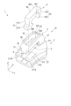
- FIG. 1 is an exploded perspective view showing the slider according to the first embodiment.
- FIG. 2 is a perspective view showing a slider according to the first embodiment.
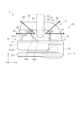
- FIG. 1 is a cross-sectional view showing a slider according to the first embodiment.
- FIG. 3 is a diagram illustrating an example of assembling the slider according to the first embodiment.
- FIG. 2 is a side view showing the slider according to the first embodiment.
- FIG. 3 is a cross-sectional view showing a slider according to a second embodiment.
- the slider 1 is configured to guide a pair of elements (not shown) of a slide fastener in a guiding direction, thereby fitting or separating the pair of elements.
- the slider 1 includes a slider body 2, a handle holder 3 erected on the slider body 2, and a closing member 4 attached to the handle holder 3.
- the pull handle 5 includes a pull main body 51 for being held by a user, and a shaft portion 52 formed at an end of the pull main body 51.
- the configuration of the slider 1 will be explained with reference to FIGS. 1 to 3.
- the direction in which the slider 1 guides the element is referred to as the X direction (front-back direction)
- the direction orthogonal to the X direction is referred to as the Y direction (left-right direction)
- the direction orthogonal to the X and Y directions is referred to as the Z direction ( (in the vertical direction and in the thickness direction of the slider body 2).
- the slider body 2 is configured to guide a pair of element rows of the slide fastener in the X direction.
- the slider body 2 includes an upper wing plate 21 and a lower wing plate 22 that are arranged to face each other in the Z direction, and a guide column 23 that connects the upper wing plate 21 and the lower wing plate 22.
- a guide path 24 is formed between the upper wing plate 21 and the lower wing plate 22, through which a pair of element rows of slide fasteners are inserted so as to be able to engage and separate.
- a pair of flange portions 211A and 211B facing each other are provided. Note that the slider body 2 can have the same configuration as the conventional one, so a detailed description thereof will be omitted here.
- a groove 212 into which a closing member 4 (to be described later) is inserted is formed along the X direction in the upper surface 210 of the upper wing plate 21 .
- the slider body 2 in this embodiment constitutes a slider body 10 that is integrally molded with the handle holder 3.
- the slider main body 10 is preferably a die-cast part, but may also be a molded product of synthetic resin or the like.
- the handle holder 3 is erected on the upper wing plate 21 of the slider body 2, and forms a shaft holding space S between it and the upper wing plate 21 in which the shaft portion 52 of the pull handle 5 is disposed.
- the shaft holding space S is a space formed between the pull handle holder 3 and the slider body 2, and the shaft portion 52 is arranged around the axis arranged along the Y direction within the shaft holding space S. It is rotatable.
- the pull holder 3 includes a first end 31, a second end 32, and a main body 33 extending between the first end 31 and the second end 32, and It is constructed in the form of a cantilever beam.
- the first end portion 31 is a fixed end portion connected to an end portion of the upper wing plate 21 in the +X direction (for example, a front end portion of the upper wing plate 21), and is a fixed end portion of the upper wing plate 21 on the +X direction side with respect to the shaft holding space S. It extends from the plate 21 in the +Z direction.
- a groove portion 311 is formed in the first end portion 31 and is open to the shaft holding space S side (that is, in the ⁇ X direction) and communicates with a through hole 33S in the main body portion 33, which will be described later.
- a fitted portion 31E that opens into the shaft holding space S via the groove 311 is formed in the groove 311 of the first end 31 (see FIG. 3).
- the fitted portion 31E may be a recess that opens into the shaft holding space S, or may be a hole that opens into the shaft holding space S.
- the second end portion 32 extends in the ⁇ X direction from the ⁇ X direction end of the main body portion 33 on the ⁇ X direction side with respect to the shaft holding space S. Specifically, the second end 32 of this embodiment faces the slider body 2 on the side opposite to the first end 31 with respect to the main body 33, and is located at the end of the upper wing plate 21 in the ⁇ X direction.
- the rear end of the upper wing plate 21 is a free end that forms an insertion gap G between the upper wing plate 21 and the rear end of the upper wing plate 21.
- the insertion gap G is a gap through which the shaft portion 52 can be inserted up to the shaft holding space S.
- the Y-direction dimension of the second end portion 32 is smaller than the Y-direction dimension of the main body portion 33 and equal to the Y-direction dimension of a through hole 33S, which will be described later, formed in the main body portion 33.
- the main body portion 33 extends along the X direction between the first end portion 31 and the second end portion 32.
- the main body part 33 of this embodiment connects the first end part 31 and the second end part 32.
- a through hole 33S is formed in this main body part 33, passing through the main body part 33 in the Z direction (see FIG. 1).
- the through hole 33S has a cross-sectional shape that extends in the X direction while having a constant dimension in the Y direction.
- the main body portion 33 has a pair of side wall portions 34A and 34B facing each other in the Y direction via the through hole 33S.
- the side wall portions 34A, 34B abut in the Y direction against a base portion 40 of the closing member 4, which will be described later.
- the pull holder 3 includes a front side surface 35 and a rear side surface 36 that face each other in the X direction via the through hole 33S (corresponding to a pair of front and rear opposing surfaces of the present invention).
- the front side surface 35 is formed from the main body 33 to the first end 31 and forms a part of the bottom of the groove 311 of the first end 31 .
- the front side surface 35 forms an inclined surface that is inclined with respect to the Z direction so as to be located in the +X direction as it goes toward the +Z direction.
- the rear side surface 36 is formed from the main body portion 33 to the second end portion 32 .
- the front side surface 35 abuts on a second leg 42 of the closure member 4, which will be described later, and the rear side surface 36 abuts on each of a base 40 and a first leg 41 of the closure member 4, which will be described later.
- the closing member 4 is, for example, a molded article of synthetic resin, and is preferably integrally formed of a flexible material. As shown in FIG. 1, the closure member 4 includes a base 40, and a first leg 41 and a second leg 42 extending from the base 40. The closing member 4 forms a shaft holding space S together with the handle holder 3 by being attached to the handle holder 3 . Below, the closing member 4 attached to the handle holder 3 will be described.
- the base 40 is disposed within the through hole 33S of the pull holder 3, that is, between the pair of side walls 34A and 34B.
- the base 40 contacts the pair of side walls 34A and 34B in the Y direction, and contacts the rear side surface 36 in the X direction.
- a semicircular groove 401 is formed along the Y direction at the end of the base 40 in the +X direction.
- a portion of the base portion 40 where the groove portion 401 is formed constitutes a flexible portion 402 that can be elastically deformed.
- the closing member 4 deforms mainly due to elastic deformation of the flexible portion 402 so that the tips of the first leg portion 41 and the second leg portion 42 approach each other.
- the first leg part 41 has a script body 411 extending in the -Z direction from the end of the base part 40 in the -X direction, and a fitting part 412 protruding from the tip of the script body 411 in the -X direction.
- the script body 411 extends along the second end 32 of the handle holder 3 and abuts the rear side surface 36 together with the base 40 .
- the fitting portion 412 engages with the second end portion 32 by fitting into the insertion gap G.
- the second leg portion 42 has a script body 421 extending from the +X direction end of the base portion 40 in the +X direction and the ⁇ Z direction, and a fitting portion 422 protruding from the tip of the script body 421 in the +X direction.
- the script body 421 extends along the first end 31 while contacting the front side surface 35 and is inserted into the groove 311 .
- the fitting portion 422 engages with the first end portion 31 by fitting into the fitted portion 31E.
- first leg portion 41 and the second leg portion 42 are each configured to be able to be inserted through the through hole 33S when the closing member 4 is attached to the handle holder 3.
- the Y-direction dimension of each of the first leg portion 41 and the second leg portion 42 is less than or equal to the gap between the pair of side wall portions 34A, 34B, that is, the Y-direction dimension of the through hole 33S.
- a method of attaching the pull tab 5 to the slider 1 will be explained.
- the operator prepares the slider body 10 before the closing member 4 is attached, and inserts the shaft portion 52 of the handle 5 into the insertion gap G of the handle holder 3. Thereby, the shaft portion 52 is accommodated in the shaft holding space S.
- the operator attaches the closing member 4 to the handle holder 3 of the slider body 10, as shown in FIG. Specifically, the first leg 41 and the second leg 42 of the closing member 4 are inserted into the through hole 33S of the handle holder 3, and the fitting part 412 of the first leg 41 is aligned with the insertion gap G. After that, the base 40 is pushed into the through hole 33S. At this time, while the flexible part 402 of the closing member 4 is elastically deformed, the second leg part 42 is guided by the front side surface 35 and advances in the -Z direction. When the second leg portion 42 gets over the front side surface 35, the flexible portion 402 returns to its original shape, and the fitting portion 422 of the second leg portion 42 fits into the fitted portion 31E from the shaft holding space S side. . Furthermore, the fitting portion 412 of the first leg portion 41 fits into the insertion gap G from the shaft holding space S side.
- the slider 1 can hold the handle 5 in the shaft holding space S as shown in FIG. If the slider 1 is to be slid in the +X direction, the shaft portion 52 of the handle 5 moves to the front position P1 within the shaft holding space S, and applies a load in a predetermined direction including a +X direction component to the slider 1.
- the predetermined direction including the +X direction component refers to the +X direction as a reference direction (for example, see arrow A1 in FIG. 5), and a predetermined angle ⁇ 1 (for example, 0 5° to 45°) (for example, see arrow A2 in FIG. 5).
- the slider 1 can receive the load applied from the shaft portion 52 at the pull holder 3 (specifically, the first end portion 31 or the pair of side wall portions 34A, 34B).
- the shaft portion 52 of the handle 5 When sliding the slider 1 in the ⁇ X direction, the shaft portion 52 of the handle 5 is guided by the inclined surface 413, moves to the rear position P2 within the recess 414 of the closing member 4, and moves in a predetermined direction including the ⁇ X direction component.
- the predetermined direction including the -X direction component refers to the -X direction as a reference direction (see arrow A3 in FIG. 5, for example), and a predetermined angle ⁇ 2 (
- the direction of rotation is from 0° to 45° (see arrow A4 in FIG. 5, for example).
- the slider 1 can receive the load applied from the shaft portion 52 on the pull holder 3 (specifically, the second end portion 32 or the pair of side wall portions 34A, 34B) via the closing member 4. can.
- the handle 5 can be removed from the slider 1.
- an arbitrary jig may be inserted into the insertion gap G and the fitting portion 412 of the first leg portion 41 may be pushed out into the shaft holding space S.
- the closing member 4 is elastically deformed, and a portion of the base 40 is pushed out from the through hole 33S to the outside of the pull handle holder 3.
- the operator can pull out the closing member 4 from the through hole 33S by grasping the portion of the base 40 pushed out from the through hole 33S. Thereafter, the operator can remove the handle 5 from the handle holder 3 via the insertion gap G.
- the handle 5 may be replaced by attaching a new handle 5.
- the shaft portion 52 of the pull handle 5 is inserted into the insertion gap G of the pull handle holder 3, and after the shaft portion 52 is housed in the shaft holding space S, the closing member 5
- the handle 5 can be attached by attaching it to the handle holder 3.
- the base 40 of the closing member 4 is disposed inside the through hole 33S in the pull holder 3, that is, between the pair of side walls 34A, 34B, and the first leg 41 of the closing member 4 extends from the base 40.
- the closing member 4 is less susceptible to interference from the outside and less likely to fall off from the handle holder 3. Therefore, a slider 1 is provided in which the pull tab 5 can be retrofitted and the pull tab 5 can be prevented from falling off. Further, the pair of side wall portions 34A and 34B can also support the load applied to the handle 5 in the Y direction.
- each of the pair of side wall portions 34A, 34B abuts against the base portion 40 in the Y direction. With such a configuration, it is possible to suppress the base portion 40 from slipping out from the through hole 33S. Thereby, falling off of the closing member 4 can be suppressed more suitably.
- the pull handle holder 3 has a front side surface 35 and a rear side surface 36 (a pair of front and rear opposing surfaces of the present invention) that face each other in the X direction via the through hole 33S. 36 abut against the closure member 4 in the X direction. With such a configuration, it is possible to suppress the base portion 40 from slipping out from the through hole 33S. Further, when the closing member 4 receives a load including an X-direction component from the shaft portion 52 of the pull handle 5, the pull holder 3 can support the closing member 4 via the front side surface 35 or the rear side surface 36. Thereby, falling off of the closing member 4 can be suppressed more suitably.
- the rear side surface 36 is formed from the main body part 33 to the second end part 32, and abuts on each of the base part 40 and the first leg part 41.
- the pull holder 3 can support the closing member 4 more suitably via the rear side surface 36. can.
- the first end 31 is formed with a fitted part 31E that opens toward the shaft holding space S, and the closing member 4 extends from the base 40 and is attached to the fitted part 31E to hold the shaft. It is preferable to further include a second leg portion 42 that fits from the space S side.
- the first leg portion 41 is fitted into the insertion gap G from the shaft holding space S side, and the second leg portion 42 is fitted into the fitted portion 31E from the shaft holding space S side. I can do it. Thereby, falling off of the closing member 4 can be suppressed more suitably.
- the slider 1A has a pull holding body 3A that forms a shaft holding space S in which the shaft portion 52 of the pull handle 5 is disposed between the slider body 2 and the slider body 2. and a closing member 4 attached to the handle holder 3A.
- the handle holder 3A includes a main body 33A that extends along the X direction and forms a shaft holding space S between the slider body 2 and the Z direction from the +X side of the main body 33A, and A first end 31 that is connected and has a first fitted portion 31E that opens toward the shaft holding space S side, and a first end 31 that extends along the Z direction from the -X side of the main body 33A; It includes a second end 32A that is connected to the slider body 2 and in which a second fitted portion 32E opening toward the shaft holding space S is formed. Note that the second end 32A of this embodiment is not a free end but a fixed end.
- the second fitted portion 32E formed at the second end portion 32A may be a hole opening into the shaft holding space S, or may be a recess opening into the shaft holding space S.
- a through hole 33S is formed in the main body portion 33A as in the first embodiment.
- This main body portion 33A has a pair of side wall portions 34A and 34B that face each other via a through hole 33S.
- an insertion gap G is formed in the main body portion 33A as a slit that is arranged to overlap the through hole 33S and divides each of the pair of side wall portions 34A and 34B into a front side portion and a rear side portion in the X direction. has been done.
- FIG. 6 illustrates the front side part 34Bf of the side wall part 34B and the rear side part 34Br of the side wall part 34B among the pair of side wall parts 34A and 34B.
- the closing member 4 includes a base 40, a first leg 41, and a second leg 42, as in the first embodiment.
- the first leg portion 41 fits into the second fitted portion 32E from the shaft holding space S side instead of the insertion gap G.
- the base 40 of the closing member 4 closes the insertion gap G by being disposed inside the through hole 33S in the pull holder 3A, that is, between the pair of side walls 34A and 34B.
- the first leg part 41 and the second leg part 42 (a pair of legs) of the closing member 4 extend from the base part 40 and connect to the first fitted part 31E and the second fitted part 32E from the shaft holding space S side. Can be fitted to Therefore, the closing member 4 is less susceptible to interference from the outside and less likely to fall off from the handle holder 3A. Therefore, according to the second embodiment, similarly to the first embodiment, a slider 1A is provided in which the pull handle 5 can be retrofitted and the pull handle 5 can be prevented from falling off.
- the second end portion 32 of the handle holder 3 may be one end portion of the main body portion 33 extending in the X direction (one end portion in the ⁇ X direction).
- the groove 311 is not formed in the first end 31 of the handle holder 3, 3A, and the fitted part 31E (or the first fitted part) is formed on the inner surface of the first end 31. 31E) may be formed.
- the closing member 4 is in contact with the handle holder 3, 3A on both sides in the X direction and on both sides in the Y direction, but does not contact the handle holder 3, 3A in either direction. It's okay.
- the slider body 2 and the pull holders 3, 3A may be individually molded and then combined to form the slider body 10.
- Back side surface front-rear direction opposing surface
- 4... Closing member 40... base, 401... groove, 402... flexible part, 41... first leg, 411... script body, 412... fitting part, 42... second leg, 421... script body, 422... fitting part, 5... Pull, 51... Pull main body, 52... Shaft, G... Insertion gap, S... Shaft holding space.
Landscapes
- Slide Fasteners (AREA)
Priority Applications (5)
| Application Number | Priority Date | Filing Date | Title |
|---|---|---|---|
| US18/856,338 US20250248491A1 (en) | 2022-04-25 | 2022-04-25 | Slider |
| JP2024517627A JP7794957B2 (ja) | 2022-04-25 | 2022-04-25 | スライダー |
| DE112022007149.4T DE112022007149T5 (de) | 2022-04-25 | 2022-04-25 | Schieber |
| CN202280094715.0A CN119031867A (zh) | 2022-04-25 | 2022-04-25 | 拉头 |
| PCT/JP2022/018732 WO2023209773A1 (ja) | 2022-04-25 | 2022-04-25 | スライダー |
Applications Claiming Priority (1)
| Application Number | Priority Date | Filing Date | Title |
|---|---|---|---|
| PCT/JP2022/018732 WO2023209773A1 (ja) | 2022-04-25 | 2022-04-25 | スライダー |
Publications (1)
| Publication Number | Publication Date |
|---|---|
| WO2023209773A1 true WO2023209773A1 (ja) | 2023-11-02 |
Family
ID=88518191
Family Applications (1)
| Application Number | Title | Priority Date | Filing Date |
|---|---|---|---|
| PCT/JP2022/018732 Ceased WO2023209773A1 (ja) | 2022-04-25 | 2022-04-25 | スライダー |
Country Status (5)
| Country | Link |
|---|---|
| US (1) | US20250248491A1 (https=) |
| JP (1) | JP7794957B2 (https=) |
| CN (1) | CN119031867A (https=) |
| DE (1) | DE112022007149T5 (https=) |
| WO (1) | WO2023209773A1 (https=) |
Citations (3)
| Publication number | Priority date | Publication date | Assignee | Title |
|---|---|---|---|---|
| JPS514807Y1 (https=) * | 1968-04-04 | 1976-02-10 | ||
| JPS6070308U (ja) * | 1983-10-21 | 1985-05-18 | ワイケイケイ株式会社 | 合成樹脂製スライドフアスナ−用スライダ− |
| JPH08266314A (ja) * | 1995-01-31 | 1996-10-15 | Ykk Kk | スライドファスナー用スライダー |
Family Cites Families (6)
| Publication number | Priority date | Publication date | Assignee | Title |
|---|---|---|---|---|
| US2657445A (en) * | 1949-05-24 | 1953-11-03 | Aero Zipp Fasteners Ltd | Slider for slide fasteners |
| JPH0721123Y2 (ja) * | 1988-10-22 | 1995-05-17 | ワイケイケイ株式会社 | 自動停止装置付スライドフアスナー用スライダー |
| HK1133363A2 (zh) * | 2009-01-23 | 2010-03-19 | 鸿兴实业股份有限公司 | 可以方便安装拉片的拉链头 |
| JP6021936B2 (ja) | 2012-11-12 | 2016-11-09 | Ykk株式会社 | スライドファスナー用の引手後付けスライダー |
| WO2016042676A1 (ja) * | 2014-09-19 | 2016-03-24 | Ykk株式会社 | スライドファスナー用のスライダー |
| CN107105830B (zh) * | 2015-02-25 | 2020-09-25 | Ykk株式会社 | 拉链用拉头 |
-
2022
- 2022-04-25 US US18/856,338 patent/US20250248491A1/en active Pending
- 2022-04-25 CN CN202280094715.0A patent/CN119031867A/zh active Pending
- 2022-04-25 WO PCT/JP2022/018732 patent/WO2023209773A1/ja not_active Ceased
- 2022-04-25 JP JP2024517627A patent/JP7794957B2/ja active Active
- 2022-04-25 DE DE112022007149.4T patent/DE112022007149T5/de active Pending
Patent Citations (3)
| Publication number | Priority date | Publication date | Assignee | Title |
|---|---|---|---|---|
| JPS514807Y1 (https=) * | 1968-04-04 | 1976-02-10 | ||
| JPS6070308U (ja) * | 1983-10-21 | 1985-05-18 | ワイケイケイ株式会社 | 合成樹脂製スライドフアスナ−用スライダ− |
| JPH08266314A (ja) * | 1995-01-31 | 1996-10-15 | Ykk Kk | スライドファスナー用スライダー |
Also Published As
| Publication number | Publication date |
|---|---|
| JP7794957B2 (ja) | 2026-01-06 |
| US20250248491A1 (en) | 2025-08-07 |
| CN119031867A (zh) | 2024-11-26 |
| DE112022007149T5 (de) | 2025-02-20 |
| JPWO2023209773A1 (https=) | 2023-11-02 |
Similar Documents
| Publication | Publication Date | Title |
|---|---|---|
| JP5008518B2 (ja) | 自動停止装置付スライドファスナー用スライダー | |
| KR100357492B1 (ko) | 차량용 인출장치 | |
| JP4701233B2 (ja) | 薄壁の開口部に取り付けるためのラッチ | |
| JP6841875B2 (ja) | 接続装置 | |
| JP6503273B2 (ja) | スライドファスナー用スライダー | |
| JPWO2012140780A1 (ja) | スライドファスナー用スライダー | |
| KR20200045751A (ko) | 냉장고 도어의 조립구조 | |
| WO2023209773A1 (ja) | スライダー | |
| US12109979B2 (en) | Locking device for opening/closing body | |
| JP2010269113A (ja) | 引出しのガイド機構 | |
| JPS63171488A (ja) | 磁気デイスクカ−トリツジの組立装置 | |
| WO2021250748A1 (ja) | スライダー | |
| US7318746B2 (en) | Card socket assembly | |
| TWI715768B (zh) | 切刀用之替換刀刃及切刀 | |
| JP6135688B2 (ja) | 両開きドア構造 | |
| JP6278863B2 (ja) | コネクタ | |
| JP7450496B2 (ja) | コンパクト容器 | |
| JP6387448B1 (ja) | ハーネス側コネクタ及びカードエッジコネクタ | |
| KR101779002B1 (ko) | 인렛커넥터용 커버장치 | |
| JP5440462B2 (ja) | コネクタ | |
| CN115538875B (zh) | 一种滑动门用导向构件及滑动门 | |
| JP3013237U (ja) | 電子機器用ケースのカバー開閉構造 | |
| JP5587738B2 (ja) | キャビネット | |
| JP2789812B2 (ja) | カセットホルダーの支持構造 | |
| WO2022210481A1 (ja) | 冷蔵庫 |
Legal Events
| Date | Code | Title | Description |
|---|---|---|---|
| 121 | Ep: the epo has been informed by wipo that ep was designated in this application |
Ref document number: 22940053 Country of ref document: EP Kind code of ref document: A1 |
|
| WWE | Wipo information: entry into national phase |
Ref document number: 202280094715.0 Country of ref document: CN |
|
| WWE | Wipo information: entry into national phase |
Ref document number: 18856338 Country of ref document: US |
|
| WWE | Wipo information: entry into national phase |
Ref document number: 2024517627 Country of ref document: JP |
|
| WWE | Wipo information: entry into national phase |
Ref document number: 112022007149 Country of ref document: DE |
|
| WWP | Wipo information: published in national office |
Ref document number: 112022007149 Country of ref document: DE |
|
| 122 | Ep: pct application non-entry in european phase |
Ref document number: 22940053 Country of ref document: EP Kind code of ref document: A1 |
|
| WWP | Wipo information: published in national office |
Ref document number: 18856338 Country of ref document: US |