WO2023204044A1 - 送風機 - Google Patents
送風機 Download PDFInfo
- Publication number
- WO2023204044A1 WO2023204044A1 PCT/JP2023/014272 JP2023014272W WO2023204044A1 WO 2023204044 A1 WO2023204044 A1 WO 2023204044A1 JP 2023014272 W JP2023014272 W JP 2023014272W WO 2023204044 A1 WO2023204044 A1 WO 2023204044A1
- Authority
- WO
- WIPO (PCT)
- Prior art keywords
- pressure surface
- main plate
- blade
- rotational direction
- shroud
- Prior art date
- Legal status (The legal status is an assumption and is not a legal conclusion. Google has not performed a legal analysis and makes no representation as to the accuracy of the status listed.)
- Ceased
Links
Images


Classifications
-
- F—MECHANICAL ENGINEERING; LIGHTING; HEATING; WEAPONS; BLASTING
- F04—POSITIVE - DISPLACEMENT MACHINES FOR LIQUIDS; PUMPS FOR LIQUIDS OR ELASTIC FLUIDS
- F04D—NON-POSITIVE-DISPLACEMENT PUMPS
- F04D1/00—Radial-flow pumps, e.g. centrifugal pumps; Helico-centrifugal pumps
-
- F—MECHANICAL ENGINEERING; LIGHTING; HEATING; WEAPONS; BLASTING
- F04—POSITIVE - DISPLACEMENT MACHINES FOR LIQUIDS; PUMPS FOR LIQUIDS OR ELASTIC FLUIDS
- F04D—NON-POSITIVE-DISPLACEMENT PUMPS
- F04D29/00—Details, component parts, or accessories
- F04D29/26—Rotors specially for elastic fluids
- F04D29/28—Rotors specially for elastic fluids for centrifugal or helico-centrifugal pumps for radial-flow or helico-centrifugal pumps
- F04D29/281—Rotors specially for elastic fluids for centrifugal or helico-centrifugal pumps for radial-flow or helico-centrifugal pumps for fans or blowers
- F04D29/282—Rotors specially for elastic fluids for centrifugal or helico-centrifugal pumps for radial-flow or helico-centrifugal pumps for fans or blowers the leading edge of each vane being substantially parallel to the rotation axis
-
- F—MECHANICAL ENGINEERING; LIGHTING; HEATING; WEAPONS; BLASTING
- F04—POSITIVE - DISPLACEMENT MACHINES FOR LIQUIDS; PUMPS FOR LIQUIDS OR ELASTIC FLUIDS
- F04D—NON-POSITIVE-DISPLACEMENT PUMPS
- F04D29/00—Details, component parts, or accessories
- F04D29/26—Rotors specially for elastic fluids
- F04D29/28—Rotors specially for elastic fluids for centrifugal or helico-centrifugal pumps for radial-flow or helico-centrifugal pumps
- F04D29/30—Vanes
-
- F—MECHANICAL ENGINEERING; LIGHTING; HEATING; WEAPONS; BLASTING
- F04—POSITIVE - DISPLACEMENT MACHINES FOR LIQUIDS; PUMPS FOR LIQUIDS OR ELASTIC FLUIDS
- F04D—NON-POSITIVE-DISPLACEMENT PUMPS
- F04D29/00—Details, component parts, or accessories
- F04D29/66—Combating cavitation, whirls, noise, vibration or the like; Balancing
-
- F—MECHANICAL ENGINEERING; LIGHTING; HEATING; WEAPONS; BLASTING
- F05—INDEXING SCHEMES RELATING TO ENGINES OR PUMPS IN VARIOUS SUBCLASSES OF CLASSES F01-F04
- F05D—INDEXING SCHEME FOR ASPECTS RELATING TO NON-POSITIVE-DISPLACEMENT MACHINES OR ENGINES, GAS-TURBINES OR JET-PROPULSION PLANTS
- F05D2240/00—Components
- F05D2240/20—Rotors
- F05D2240/30—Characteristics of rotor blades, i.e. of any element transforming dynamic fluid energy to or from rotational energy and being attached to a rotor
- F05D2240/305—Characteristics of rotor blades, i.e. of any element transforming dynamic fluid energy to or from rotational energy and being attached to a rotor related to the pressure side of a rotor blade
-
- F—MECHANICAL ENGINEERING; LIGHTING; HEATING; WEAPONS; BLASTING
- F05—INDEXING SCHEMES RELATING TO ENGINES OR PUMPS IN VARIOUS SUBCLASSES OF CLASSES F01-F04
- F05D—INDEXING SCHEME FOR ASPECTS RELATING TO NON-POSITIVE-DISPLACEMENT MACHINES OR ENGINES, GAS-TURBINES OR JET-PROPULSION PLANTS
- F05D2240/00—Components
- F05D2240/20—Rotors
- F05D2240/30—Characteristics of rotor blades, i.e. of any element transforming dynamic fluid energy to or from rotational energy and being attached to a rotor
- F05D2240/306—Characteristics of rotor blades, i.e. of any element transforming dynamic fluid energy to or from rotational energy and being attached to a rotor related to the suction side of a rotor blade
Definitions
- the present disclosure relates to a blower.
- blowers have been known to suppress separation of airflow near the shroud ring by tilting the parts near the shroud ring on the leading edge side of multiple blades more forward in the rotational direction than the parts near the main plate. (For example, see Patent Document 1).
- An object of the present disclosure is to provide a blower that can suppress the flow velocity distribution near the leading edge of a blade.
- the blower is shaft and a centrifugal fan coupled to the shaft;
- the centrifugal fan is a plurality of wings arranged around the axis of the shaft; a shroud connected to a first blade tip located on one side in the axial direction of the shaft of each of the plurality of blades, and formed with an intake hole through which air is sucked; a main plate connected to a second wing tip located on the other side in the axial direction of each of the plurality of wings;
- the plurality of wings have a leading edge portion forming an inner peripheral portion and a trailing edge portion forming an outer peripheral portion, The leading edge is divided into a predetermined number of equal lengths along the leading edge, and the trailing edge is divided into a predetermined number of equal lengths along the trailing edge.
- One or more intermediate parts located equally between the edge and the rear edge are divided into a predetermined number of equal lengths along the intermediate part, and the front edge, the rear edge, and the intermediate part are divided into equal parts.
- a line connecting the plurality of dividing points in each of the points that are the same when counted from one side of the first wing tip and the second wing tip is defined as an imaginary streamline (IL)
- IL imaginary streamline
- a suction surface of an air inflow region located closer to a leading edge than a trailing edge on an imaginary streamline is provided with a convex portion that protrudes so as to approach a pressure surface of an adjacent blade; At least a portion of the positive pressure surface of the air inflow region is inclined so as to be located on the front side in the rotational direction as it approaches the main plate.
- a convex part provided on the suction side of the blade applies a force to a part of the airflow flowing along the suction side of the blade in a direction away from the suction side, causing the airflow to flow toward the pressure side. It becomes easier. Therefore, the difference between the flow velocity of the airflow on the suction side and the airflow on the pressure side becomes small, and the flow velocity distribution near the leading edge of the blade can be suppressed.
- the pressure surface of the blade is affected by centrifugal force due to the bending of the flow path formed between the blades, and vortices are generated in a relationship of balance with the velocity boundary layer of the pressure surface. This vortex tends to increase when the flow velocity of the airflow is high on the positive pressure side as in the present case.
- At least a portion of the positive pressure surface of the air inflow portion is inclined so as to be located on the front side in the rotation direction as it approaches the main plate. According to this, it becomes easier for force to act in a direction that suppresses the generation or development of vortices on the pressure side of the blade, and it is possible to suppress problems caused by vortices on the pressure side.
- blower of the present disclosure it is possible to suppress the flow velocity distribution near the leading edge of the blade, and to suppress problems such as an increase in pressure loss and worsening of noise caused by the flow velocity distribution.
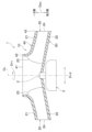
- FIG. 2 is a schematic plan view of a blower according to an embodiment. 2 is a sectional view taken along line II-II in FIG. 1.
- FIG. FIG. 3 is an explanatory diagram for explaining virtual streamlines. It is an explanatory view for explaining the blade shape of the centrifugal fan of the blower used as a comparative example.
- FIG. 6 is an explanatory diagram for explaining the flow velocity distribution near the leading edge of a centrifugal fan of a blower as a comparative example. It is an explanatory view for explaining the blade shape of the centrifugal fan of the blower concerning an embodiment.
- 4 is a sectional view taken along VII-VII in FIG. 3.
- FIG. 4 is a sectional view taken along line VIII-VIII in FIG. 3.
- FIG. 4 is a sectional view taken along line IX-IX in FIG. 3.
- FIG. 4 is a sectional view taken along line XX in FIG. 3.
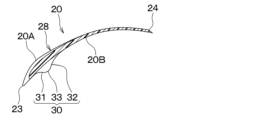
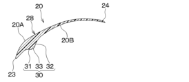
- FIG. 2 is a schematic cross-sectional view of a typical blade in the centrifugal fan of the blower according to the embodiment.
- 12 is a sectional view taken along line XII-XII in FIG. 11.
- FIG. 12 is a sectional view taken along line XIII-XIII in FIG. 11.
- FIG. 12 is a sectional view taken along line XIV-XIV in FIG. 11.
- FIG. 12 is a sectional view taken along line XV-XV in FIG. 11.
- FIG. 3 is an explanatory diagram for explaining airflow along the blades of the centrifugal fan of the blower according to the embodiment.
- FIG. 2 is an explanatory diagram for explaining the flow velocity distribution near the leading edge of the centrifugal fan of the blower according to the embodiment.
- FIG. 3 is an explanatory diagram for explaining the effect of suppressing vortices on the pressure side of the blade.
- FIG. 3 is an explanatory diagram for explaining the effect of reducing pressure loss.
- the blower 1 shown in FIGS. 1 and 2 is applied to, for example, an indoor air conditioner.
- the blower 1 includes a casing, a shaft 2, an electric motor 3, and a centrifugal fan 10 (not shown).
- the casing is the housing of the blower 1.
- the casing protects the shaft 2, electric motor 3, centrifugal fan 10, etc. from dust and dirt outside the blower 1.
- a shaft 2, an electric motor 3, and a centrifugal fan 10 are housed inside the casing.
- the casing is provided with an air inlet and an air outlet.
- the shaft 2 is a rotating shaft in the blower 1.
- the shaft 2 is a cylindrical bar.
- the shaft 2 is made of metal such as iron, stainless steel, or brass.
- the direction along the axis CL of the shaft 2 is illustrated as the axial direction Dax, the direction away from the axis CL of the shaft 2 as the radial direction Drd, and the direction in which the shaft 2 and the centrifugal fan 10 rotate as the rotation direction Drt. ing.
- the electric motor 3 is a drive section in the blower 1.
- the electric motor 3 rotates the shaft 2 and the centrifugal fan 10 around the axis CL of the shaft 2 by being energized.
- the electric motor 3 is, for example, an outer rotor type brushless DC motor.
- the centrifugal fan 10 is an impeller applied to the blower 1.
- a centrifugal fan 10 is connected to the shaft 2.
- the centrifugal fan 10 rotates integrally with the shaft 2 around the axis CL of the shaft 2 when the electric motor 3 is driven by energization.
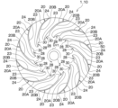
- the centrifugal fan 10 includes a plurality of blades 20 arranged around an axis CL of a shaft 2, a shroud 40 connected to one side of each of the plurality of blades 20 in the axial direction Dax, and a shroud 40 connected to one side of each of the plurality of blades 20 in the axial direction Dax. and a main plate 50 connected to the other side in the axial direction Dax.
- the plurality of blades 20 are arranged at intervals in the rotational direction Drt of the shaft 2.
- Each of the plurality of wings 20 has the same shape.
- Each of the plurality of blades 20 has a first blade tip 21 that is an end on one side in the axial direction Dax, and a second blade tip 22 that is an end on the other side in the axial direction Dax.
- the plurality of wings 20 each have a leading edge 23 that constitutes an inner peripheral portion and a trailing edge 24 that constitutes an outer peripheral portion.
- the distance from the axis CL of the front edge portion 23 decreases from one side to the other side in the axial direction Dax.
- the front edge portion 23 is curved so that the angle with the axis CL decreases from one side to the other side in the axial direction Dax.
- the rear edge portion 24 extends along the axis CL.
- the plurality of blades 20 have a pressure surface 20A and a suction surface 20B forming a blade shape.
- the positive pressure surface 20A is a first wing surface located on the forward side in the rotation direction Drt.
- the negative pressure surface 20B is a second wing surface located on the rear side in the rotation direction Drt.
- an inter-blade flow path 29 through which air flows is formed between adjacent blades 20.
- the shroud 40 has an annular shape that expands in the radial direction Drd.
- the shroud 40 is connected to the first wing tips 21 of the plurality of wings 20.
- the shroud 40 has an intake hole 41 formed on its inner peripheral side through which air is sucked.
- the shroud 40 has an inner circumferential end portion 42 that constitutes an inner circumferential portion, and an outer circumferential end portion 43 that constitutes an outer circumferential portion.
- An inner peripheral end portion 42 of the shroud 40 forms an intake hole 41 .
- the shroud 40 has an inner circumferential end 42 side that protrudes upward along the axial direction Dax so that air can easily flow into the intake hole 41. Further, the shroud 40 has an outer peripheral end 43 extending in a direction intersecting the axial direction Dax.
- the main plate 50 has a disc shape that expands in the radial direction Drd.
- the main plate 50 is connected at its inner peripheral side to the shaft 2 by a cap (not shown).
- the main plate 50 is connected to the second wing tips 22 of the plurality of wings 20.
- the main plate 50 extends in a direction intersecting the axial direction Dax.
- the centrifugal fan 10 of this embodiment is configured as a closed fan in which both sides in the axial direction Dax are covered with a shroud 40 and a main plate 50.
- the centrifugal fan 10 may have a plurality of blades 20, a shroud 40, and a main plate 50 formed as an integral structure by injection molding or the like, or a plurality of blades 20, a shroud 40, and a main plate configured separately. 50 may be formed by being joined by adhesive or the like.
- the centrifugal fan 10 of this embodiment is a turbo fan, and the portion of the blade 20 on the trailing edge 24 side is inclined in the opposite direction to the rotational direction Drt of the shaft 2.
- the centrifugal fan 10 rotates around the axis CL of the shaft 2, it sucks in air from one side in the axial direction Dax. Then, the centrifugal fan 10 blows out the air sucked in from one side in the axial direction Dax in a direction away from the axis CL of the shaft 2 (that is, in the radial direction Drd).
- the centrifugal fan 10 includes a mixed flow fan that blows air sucked in from one side in the axial direction Dax in a direction inclined with respect to the axis CL of the shaft 2.
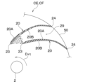
- the centrifugal fan 10 flows along, for example, virtual streamlines IL1 to IL4 shown in FIG. 3. The virtual streamlines IL1 to IL4 will be explained below with reference to FIG. 3.
- the virtual streamlines IL1 to IL4 include a plurality of division points Xa set on the front edge 23, a plurality of division points Xb set on the rear edge 24, and a plurality of intermediate points between the front edge 23 and the rear edge 24. This is a line connecting a plurality of dividing points Xc, Xd, and Xe set in portions 25, 26, and 27 in a predetermined order.
- the plurality of division points Xa provided on the front edge 23 are obtained by dividing the front edge 23 into a predetermined number of parts so that the lengths along the front edge 23 are equal.
- FIG. 3 shows the front edge 23 divided into three parts at four division points Xa1 to Xa4, the number of divisions of the front edge 23 is different from that shown in FIG. You can leave it there.
- the plurality of dividing points Xb provided on the trailing edge 24 are obtained by dividing the trailing edge 24 into a predetermined number of parts so that the lengths along the trailing edge 24 are equal.
- the trailing edge portion 24 is divided into three parts at four dividing points Xb1 to Xb4, but the number of divisions of the trailing edge portion 24 is different from that shown in FIG. You can leave it there. Note that the number of parts into which the rear edge part 24 is divided needs to be the same as the number of parts into which the front edge part 23 is divided.
- the plurality of intermediate portions 25, 26, and 27 are portions that are equally divided between the leading edge portion 23 and the trailing edge portion 24 in each of the plurality of wings 20.
- the plurality of dividing points Xc, Xd, and Xe provided in the plurality of intermediate portions 25, 26, and 27 divide the plurality of intermediate portions 25, 26, and 27 into lengths along the plurality of intermediate portions 25, 26, and 27. It is divided into a predetermined number of equal parts.
- a plurality of intermediate portions 25, 26, 27 are divided into three at four division points Xc1 to Xc4, Xd1 to Xd4, and Xe1 to Xe4. , 27 may be divided into different numbers than shown in FIG. Note that the number of parts into which the plurality of intermediate parts 25, 26, and 27 are divided needs to be the same as the number of parts into which the front edge part 23 and the rear edge part 24 are divided.
- the lines connecting the lines that have the same number when counted from the side are defined as virtual streamlines IL1 to IL4.
- the dividing points are counted from the second wing tip 22 side.
- the lines connecting the lines that have the same number when the lines are the same may be used as the virtual streamlines IL1 to IL4.
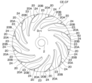
- FIG. 4 is an explanatory diagram for explaining the blade shape of the centrifugal fan CF of the blower CE, which is a comparative example of the present embodiment.
- FIG. 4 shows a plan view of the centrifugal fan CF with the shroud 40 removed.
- the same reference numerals are given to the parts in the centrifugal fan CF of the comparative example that correspond to the centrifugal fan 10 of the present embodiment.
- the plurality of blades 20 of the centrifugal fan CF have curved positive pressure surfaces 20A and negative pressure surfaces 20B.
- air flows through the inter-blade flow path 29 formed between the adjacent blades 20.
- FIG. Tend Such a flow velocity distribution is undesirable because it causes an increase in pressure loss and aggravation of noise.
- the centrifugal fan 10 of the present embodiment has an air inflow section 28 adjacent to the suction surface 20B of the air inflow section 28 near the leading edge 23 of the plurality of blades 20, as shown in FIG.
- a convex portion 30 is provided that protrudes so as to approach the pressure surface 20A of the blade 20.
- the air inflow region 28 is a region closer to the front edge 23 than the rear edge 24 on the virtual streamline IL. Specifically, the air inflow portion 28 is a portion of the blade 20 that is closer to the axis CL than the intermediate portion 26 located at the center of the plurality of intermediate portions 25, 26, and 27.
- the convex portion 30 turns the direction of the airflow along the suction surface 20B of the blade 20 toward the pressure surface 20A of the adjacent blade 20. As shown in FIGS. 7, 8, and 9, the convex portion 30 is provided on the air flow downstream side of the front edge portion 23 in the air inflow portion 28. As shown in FIGS. The convex portion 30 is inclined with respect to the negative pressure surface 20B so that a first portion 31 on the upstream side of the air flow near the leading edge 23 approaches the positive pressure surface 20A, and a first portion 31 on the downstream side of the air flow away from the leading edge 23 is inclined toward the negative pressure surface 20B. The two portions 32 are inclined with respect to the negative pressure surface 20B so as to be separated from the positive pressure surface 20A.
- the convex portion 30 has a curved surface at the connecting portion with the negative pressure surface 20B so that no steps or corners are formed in the connecting portion between the negative pressure surface 20B and the first portion 31 and the connecting portion between the second portion 32 and the negative pressure surface 20B. It has become.
- the blade 20 configured in this manner has a concave shape at the intersection of the first portion 31 of the convex portion 30 and the negative pressure surface 20B near the leading edge 23, so that airflow along the negative pressure surface 20B is improved. is turned toward the positive pressure surface 20A.
- the plate thickness at the portion including the convex portion 30 must be set relative to the plate thickness at the minimum inner diameter position of the positive pressure surface 20A. , it is desirable that the maximum value is 1.5 times or more.
- the length of the line segment connecting the intersection of the pressure surface 20A and a virtual circle having a predetermined radius centered on the axis CL and the intersection of the virtual circle and the suction surface 20B is defined as the length of the blade 20.
- the board is thick.
- the convex portion 30 is provided in a section of the negative pressure surface 20B from the virtual streamline IL2 to the virtual streamline IL4. Specifically, the convex portion 30 is not provided near the first wing tip portion 21 on one side in the axial direction Dax in the air inflow portion 28, as shown in FIGS. 7 and 8. As shown in FIG. 9, the convex portion 30 is provided near the second wing tip portion 22 on the other side of the air inlet portion 28 in the axial direction Dax.
- a virtual line that is equidistant from the one on both end sides in the axial direction Dax is defined as the intermediate virtual streamline IL5.
- the position in the axial direction Dax where the plate thickness of the blade 20 along the rotational direction Drt is maximum at the portion where the convex portion 30 is provided on the suction surface 20B is close to the main plate 50 with respect to the intermediate virtual streamline IL5.
- the top portion 33 between the first portion 31 and the second portion 32 is set at a position closer to the main plate 50 than the intermediate virtual streamline IL5.
- the protruding height of the convex portion 30 is smaller than the distance between adjacent blades 20 in the portion where the convex portion 30 is not provided.
- the protrusion height of the convex portion 30 is, for example, less than half the distance between adjacent blades 20 in a portion where the convex portion 30 is not provided.
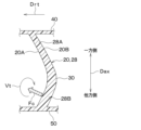
- the pressure surface 20A of the blade 20 is affected by centrifugal force due to the bending of the inter-blade flow path 29, and a vortex Vt is generated in a relationship of balance with the velocity boundary layer of the pressure surface 20A.
- This vortex Vt becomes noticeable in a configuration in which the flow velocity of the airflow on the positive pressure surface 20A side is increased due to the convex portion 30 provided on the negative pressure surface 20B side, as in the present invention.
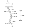
- a part of the positive pressure surface 20A of the air inflow portion 28 is inclined so as to be located on the front side in the rotation direction Drt as it approaches the main plate 50.
- At least a portion of the positive pressure surface 20A of the air inflow portion 28 on the side closer to the main plate 50 is positioned on the front side in the rotation direction Drt as it approaches the main plate 50. It is sloping. That is, the positive pressure surface 20A of the air inflow portion 28 is inclined so that the lower blade portion 28B near the main plate 50 is located at a position advanced in the rotational direction Drt as it approaches the main plate 50.
- the positive pressure surface 20A of the air inflow portion 28 is inclined so that at least a portion of the side closer to the shroud 40 is located on the front side in the rotation direction Drt as it approaches the shroud 40. That is, the positive pressure surface 20A of the air inflow portion 28 is inclined so that the upper blade portion 28A near the shroud 40 is located at a position advanced in the rotational direction Drt as it approaches the shroud 40.
- a line connecting a point P1 located furthest forward in the rotational direction Drt and a point P2 located furthest rearward in the rotational direction Drt in the upper blade portion 28A of the air inflow portion 28 is It is assumed that the main plate side reference line Lm.
- a line connecting a point P3 located furthest forward in the rotational direction Drt and a point P2 located furthest rearward in the rotational direction Drt in the lower wing portion 28B of the air inflow portion 28 is connected to the shroud side. Let it be the reference line Ls.
- the main plate side reference line Lm and the shroud side reference line Ls are inclined with respect to the plane PL along the axis CL.
- the angle ⁇ m between the main plate side reference line Lm and the plane PL along the axis CL is smaller than the angle ⁇ s between the shroud side reference line Ls and the plane PL along the axis CL.
- a point P1 located furthest forward in the rotational direction Drt among the sides closest to the main plate 50 is further forward in the rotational direction Drt than a point P3 located furthest forward in the rotational direction Drt among the sides closest to the shroud 40. It is located in Further, on the positive pressure surface 20A, a point P2 located furthest to the rear in the rotational direction Drt is located closer to the main plate 50 than the shroud 40.
- the upper blade portion 28A of the air inlet portion 28 is arranged in the direction of rotation most in the rotational direction Drt such that the inlet angle of the blade 20 in the upper blade portion 28A is smaller than the inlet angle of the blade 20 in the centrifugal fan CF of the comparative example shown in FIG.
- the position of point P1 located on the front side is set. According to this, the angle of incidence of the incoming air to the blades 20 in the upper blade portion 28A can be made smaller than the angle of incidence of the incoming air to the blades 20 of the centrifugal fan CF of the comparative example. As a result, separation of the airflow from the blades 20 that occurs near the shroud 40 can be reduced.
- the inlet angle is the angle between the tangent to the inscribed circle at the leading edge 23 of the blade 20 and the blade chord line.
- the inscribed circle is a virtual circle that contacts each of the plurality of blades 20 on the inside in the radial direction Drd.
- the leading edge portion 23 is a portion of the wing 20 that is in contact with the inscribed circle.
- the chord line is a straight line connecting the leading edge 23 and trailing edge 24 of the blade 20.
- the incident angle is the difference between the inlet angle and the inlet angle of the incoming air at the leading edge 23 of the blade 20.
- the inflow angle is the angle between the tangent to the inscribed circle at the position of the leading edge 23 of the blade 20 and the direction of the flow velocity vector of the inflowing air.
- the lower blade portion 28B of the air inflow portion 28 changes so that as it moves away from the main plate 50, the inclination toward the front side in the rotational direction Drt becomes smaller. Specifically, as shown in FIGS. 12, 13, and 14, the forward inclination of the rotational direction Drt gradually decreases as the distance from the leading edge 23 of the blade 20 increases.
- FIG. 12 is a cross-sectional view of the blade 20 at a position where the forward inclination in the rotational direction Drt is maximum.
- FIG. 13 is a cross-sectional view of the blade 20 at a position where the plate thickness of the blade 20 along the rotational direction Drt is maximum at a portion of the negative pressure surface 20B where the convex portion 30 is provided, as shown in FIG.
- FIG. 14 is a cross-sectional view of the blade 20 at a position closer to the leading edge 23 than the trailing edge 24 on the virtual streamline IL.
- FIG. 15 is a cross-sectional view of the blade 20 at a position where the chord length Lw of the second blade tip 22 is intermediate.
- the inclination start position Px1 is set approximately midway between the shroud 40 and the main plate 50.
- the plate thickness maximum position Px2 when the position in the axial direction Dax where the plate thickness of the blade 20 along the rotational direction Drt is maximum at the portion of the suction surface 20B where the convex portion 30 is provided is defined as the plate thickness maximum position Px2, the plate thickness maximum position Px2 is , is set closer to the main plate 50 than the shroud 40. Specifically, the plate thickness maximum position Px2 is set close to the main plate 50 with respect to the inclination start position Px1.
- the position where the pressure surface 20A of the lower wing portion 28B is no longer tilted forward in the rotational direction Drt is at the leading edge 23 on the virtual streamline IL. Specifically, the position where the forward inclination in the rotational direction Drt on the pressure surface 20A of the lower blade portion 28B disappears is at the leading edge with respect to the intermediate position of the chord length Lw in the second blade tip 22. Close to 23.
- the centrifugal fan 10 rotates in the rotation direction Drt together with the shaft 2. At this time, the blades 20 of the centrifugal fan 10 give momentum to the air. Thereby, the centrifugal fan 10 sucks air from the intake hole 41 toward the inter-blade flow path 29, and blows out the air in the inter-blade flow path 29 toward the outside of the centrifugal fan 10 in the radial direction Drd.
- the blade 20 of this embodiment is provided with a convex portion 30 on the negative pressure surface 20B of the air inflow portion 28 so as to protrude toward the pressure surface 20A of the adjacent blade 20.
- a force is applied to a part of the airflow flowing along the suction surface 20B of the blade 20 in a direction away from the suction surface 20B by the convex portion 30 provided on the suction surface 20B of the blade 20.
- airflow tends to flow toward the positive pressure surface 20A.
- FIG. 17 the flow velocity of the airflow on the negative pressure surface 20B side becomes smaller and the flow velocity of the airflow on the positive pressure surface 20A side increases. The difference with the airflow velocity becomes smaller.
- the blade 20 of this embodiment is inclined so that as the pressure surface 20A approaches the main plate 50, it is located on the front side in the rotation direction Drt. Therefore, as shown in FIG. 18, the force Fc tends to act in a direction that suppresses the generation or development of the vortex Vt on the pressure surface 20A side of the blade 20, making it possible to suppress problems caused by the vortex Vt on the pressure surface 20A side. can.
- the blower 1 of the present embodiment it is possible to suppress the flow velocity distribution near the leading edge portion 23 of the blade 20, and to suppress problems caused by the vortices Vt on the pressure surface 20A side due to the suppression of the flow velocity distribution. Problems caused by the vortex Vt on the positive pressure surface 20A side include increased pressure loss, worsened noise, and the like. As shown in FIG. 19, the blower 1 of the present invention can suppress an increase in pressure loss compared to the blower CE of the comparative example shown in FIG.
- the part of the positive pressure surface 20A of the air inflow part 28 that is closer to the main plate 50 is inclined so as to be located on the front side in the rotation direction Drt as it approaches the main plate 50. There is. This makes it easier for force to act in a direction that suppresses the generation or development of the vortex Vt on the pressure surface 20A side of the blade 20, and it is possible to suppress problems caused by the vortex Vt on the pressure surface 20A side.
- a portion of the positive pressure surface 20A of the air inflow portion 28 that is closer to the shroud 40 is inclined so that as it approaches the shroud 40, it is located on the front side in the rotation direction Drt. According to this, the inflow angle of the airflow to the blade 20 in the vicinity of the shroud 40 can be reduced, and separation of air in the vicinity of the shroud 40 can be suppressed.
- the configuration is such that the generation of the vortex Vt can be suppressed while making the slope of the air inlet portion 28 gentle. It is desirable to be present.
- the flow velocity on the shroud 40 side is lower than that on the main plate 50 side, noise is unlikely to become a problem even if the slope at the air inlet portion 28 is increased to obtain the effect of suppressing air separation near the shroud 40.
- the blade 20 has an angle ⁇ m between the main plate side reference line Lm and the plane PL along the axis CL, which is smaller than an angle ⁇ s between the shroud side reference line Ls and the plane PL along the axis CL. It has become.
- the blower 1 that can suppress air separation near the shroud 40 while suppressing the flow velocity distribution near the leading edge 23 of the blade 20 can be designed to be suitable for suppressing noise generation.
- the position where the pressure surface 20A of the lower wing portion 28B is no longer inclined forward in the rotational direction Drt is close to the leading edge 23 on the virtual streamline IL.
- the position where the forward inclination in the rotational direction Drt on the pressure surface 20A of the lower blade portion 28B disappears is the position where the protrusion 30 is provided on the suction surface 20B, and the plate of the blade 20 along the rotational direction Drt.
- the thickness be further away from the axis CL than the position where the thickness is maximum.
- the positive pressure surface 20A of the air inflow portion 28 changes such that its inclination in the rotational direction Drt becomes smaller as a portion of the lower blade portion 28B moves away from the leading edge 23.
- the position where the forward inclination in the rotational direction Drt on the pressure surface 20A of the lower wing portion 28B disappears is closer to the leading edge portion 23 than the midpoint of the chord length Lw in the second wing tip portion 22. . According to this, the generation or development of the vortex Vt on the pressure surface 20A of the blade 20 can be suppressed.
- the difference in airflow velocity between the suction surface 20B side and the pressure surface 20A side of the blade 20 tends to increase more easily on the main plate 50 side than on the shroud 40 side. For this reason, it is desirable that the plate thickness maximum position Px2 be set close to the main plate 50 with respect to the intermediate virtual streamline IL5. In this way, the difference in airflow velocity between the suction surface 20B side and the pressure surface 20A side of the blade 20 can be sufficiently suppressed.
- substantially the entire positive pressure surface 20A of the air inflow portion 28 on the side closer to the main plate 50 is inclined so as to be located on the front side in the rotation direction Drt as it approaches the main plate 50.
- a portion of the positive pressure surface 20A of the air inflow portion 28 on the side closer to the main plate 50 may not be inclined toward the front side in the rotation direction Drt.
- the centrifugal fan 10 is inclined so that the part of the positive pressure surface 20A of the air inflow part 28 that is closer to the shroud 40 is located on the front side in the rotation direction Drt as it approaches the shroud 40. It is not limited to this. In the centrifugal fan 10, for example, a portion of the positive pressure surface 20A of the air inflow portion 28 that is closer to the shroud 40 does not need to be inclined toward the front side in the rotation direction Drt.
- the angle ⁇ m between the main plate side reference line Lm and the plane PL along the axis CL is smaller than the angle ⁇ s between the shroud side reference line Ls and the plane PL along the axis CL. This is desirable, but not limited to this.
- the angle ⁇ m between the main plate side reference line Lm and the plane PL along the axis CL is greater than or equal to the angle ⁇ s between the shroud side reference line Ls and the plane PL along the axis CL. You can leave it there.
- the position where the forward inclination in the rotational direction Drt on the pressure surface 20A of the lower blade portion 28B is eliminated is near the leading edge portion 23 with respect to the intermediate position of the chord length Lw in the second blade tip portion 22. Although it is desirable that it be set to , it does not have to be.
- the maximum plate thickness position Px2 is desirably set close to the main plate 50 with respect to the inclination start position Px1, but the present invention is not limited thereto.
- the plate thickness maximum position Px2 may be set near the shroud 40 with respect to the inclination start position Px1.
- the plate thickness maximum position Px2 does not need to be set near the main plate 50 with respect to the intermediate virtual streamline IL5.
- the centrifugal fan 10 is configured as a turbo fan, but the centrifugal fan 10 is not limited to this.
- the centrifugal fan 10 may be composed of a sirocco fan or a radial fan. Further, the centrifugal fan 10 may be configured as a mixed flow fan.
- an indoor air conditioner is illustrated as an application target of the blower 1 of the present disclosure, but the blower 1 can be applied to devices other than indoor air conditioners.
- the present disclosure includes the following aspects.
- a blower a shaft (2); a centrifugal fan (10) connected to the shaft;
- the centrifugal fan is a plurality of wings (20) arranged around the axis (CL) of the shaft; a shroud (40) connected to a first wing tip (21) located on one side in the axial direction of the shaft in each of the plurality of wings, and formed with an intake hole (41) through which air is sucked; a main plate (50) connected to a second wing tip (22) located on the other side in the axial direction of each of the plurality of wings,
- the plurality of wings have a leading edge (23) forming an inner circumferential portion and a trailing edge (24) forming an outer circumferential portion,
- the front edge is divided into a predetermined number of equal lengths along the front edge
- the rear edge is divided into the predetermined number of equal lengths along the rear edge.
- one or more intermediate portions located at positions equally divided between the front edge portion and the rear edge portion are arranged so that the lengths along the intermediate portions are equal. Divided into a predetermined number of parts, among a plurality of dividing points in each of the leading edge, the trailing edge, and the intermediate part, the points are the same when counted from one side of the first wing tip and the second wing tip.
- the line connecting the numbers is an imaginary streamline (IL)
- the suction surface (20B) of the air inflow portion (28) which is closer to the leading edge than the trailing edge on the virtual streamline, has a positive pressure surface (20A) of the adjacent blade.
- the positive pressure surface of the air inflow portion is inclined such that at least a portion of the side closer to the main plate is located on the front side in the rotational direction as it approaches the main plate, and at least a portion of the side closer to the shroud is inclined.
- the blower according to the first aspect wherein the blower is inclined so as to be located on the front side in the rotation direction as it approaches the shroud.
- a line connecting a point located furthest forward in the rotational direction and a point furthest rearward in the rotational direction on the positive pressure surface of the air inflow portion on the side closest to the main plate is defined as the main plate side reference line (Lm ), and the shroud side is a line connecting the point located most forward in the rotational direction and the point located most rearward in the rotational direction on the positive pressure surface of the air inflow portion on the side closest to the shroud.
- Ls reference line
- an angle ( ⁇ m) between the main plate side reference line and a plane along the axis is smaller than an angle ( ⁇ s) between the shroud side reference line and a plane along the axis. blower.
- the positive pressure surface of the air inflow portion changes such that as at least a portion of the side closer to the main plate moves away from the main plate, the inclination toward the front side in the rotational direction becomes smaller;
- the position where the forward inclination in the rotation direction on the pressure surface of the blade on the side close to the main plate disappears is close to the leading edge on the virtual streamline, and the convex portion on the suction surface is provided.
- the positive pressure surface of the air inflow portion changes so that as at least a portion of the side closer to the main plate moves away from the front edge, the inclination toward the front side in the rotation direction becomes smaller;
- the position where the pressure surface of the blade on the side closer to the main plate is no longer tilted forward in the rotational direction is at the leading edge with respect to the midpoint of the chord length at the second blade tip.
- the positive pressure surface of the air inflow portion changes so that its inclination toward the front side in the rotational direction becomes smaller as it moves away from the leading edge,
- the position in the axial direction where the plate thickness of the blade along the rotational direction is maximum at the portion where the convex portion is provided on the negative pressure surface is the position in the rotational direction on the pressure surface of the blade on the side closer to the main plate.
Landscapes
- Engineering & Computer Science (AREA)
- Mechanical Engineering (AREA)
- General Engineering & Computer Science (AREA)
- Structures Of Non-Positive Displacement Pumps (AREA)
Priority Applications (3)
| Application Number | Priority Date | Filing Date | Title |
|---|---|---|---|
| DE112023001980.0T DE112023001980T5 (de) | 2022-04-21 | 2023-04-06 | Gebläse |
| CN202380034782.8A CN119053792A (zh) | 2022-04-21 | 2023-04-06 | 送风机 |
| US18/914,807 US12448983B2 (en) | 2022-04-21 | 2024-10-14 | Blower |
Applications Claiming Priority (2)
| Application Number | Priority Date | Filing Date | Title |
|---|---|---|---|
| JP2022-070248 | 2022-04-21 | ||
| JP2022070248A JP7697401B2 (ja) | 2022-04-21 | 2022-04-21 | 送風機 |
Related Child Applications (1)
| Application Number | Title | Priority Date | Filing Date |
|---|---|---|---|
| US18/914,807 Continuation US12448983B2 (en) | 2022-04-21 | 2024-10-14 | Blower |
Publications (1)
| Publication Number | Publication Date |
|---|---|
| WO2023204044A1 true WO2023204044A1 (ja) | 2023-10-26 |
Family
ID=88419881
Family Applications (1)
| Application Number | Title | Priority Date | Filing Date |
|---|---|---|---|
| PCT/JP2023/014272 Ceased WO2023204044A1 (ja) | 2022-04-21 | 2023-04-06 | 送風機 |
Country Status (5)
| Country | Link |
|---|---|
| US (1) | US12448983B2 (https=) |
| JP (1) | JP7697401B2 (https=) |
| CN (1) | CN119053792A (https=) |
| DE (1) | DE112023001980T5 (https=) |
| WO (1) | WO2023204044A1 (https=) |
Citations (3)
| Publication number | Priority date | Publication date | Assignee | Title |
|---|---|---|---|---|
| JP2012193740A (ja) * | 2012-07-02 | 2012-10-11 | Mitsubishi Electric Corp | ターボファンおよび空気調和機 |
| US20150275922A1 (en) * | 2013-05-10 | 2015-10-01 | Lg Electronics Inc. | Centrifugal fan and method of manufacturing the same |
| WO2017090347A1 (ja) * | 2015-11-23 | 2017-06-01 | 株式会社デンソー | ターボファンおよびそのターボファンの製造方法 |
Family Cites Families (18)
| Publication number | Priority date | Publication date | Assignee | Title |
|---|---|---|---|---|
| US6042335A (en) * | 1998-05-04 | 2000-03-28 | Carrier Corporation | Centrifugal flow fan and fan/orifice assembly |
| CN1160516C (zh) * | 1998-05-13 | 2004-08-04 | 松下电器产业株式会社 | 电动送风机及采用它的电动吸尘器 |
| US6860715B2 (en) * | 2003-04-24 | 2005-03-01 | Borgwarner Inc. | Centrifugal compressor wheel |
| JPWO2009139422A1 (ja) * | 2008-05-14 | 2011-09-22 | ダイキン工業株式会社 | 遠心送風機 |
| JP5274278B2 (ja) * | 2009-01-28 | 2013-08-28 | 三菱電機株式会社 | ターボファン及びターボファンを備えた空気調和装置 |
| JP4994421B2 (ja) * | 2009-05-08 | 2012-08-08 | 三菱電機株式会社 | 遠心ファン及び空気調和機 |
| JP5164932B2 (ja) * | 2009-06-11 | 2013-03-21 | 三菱電機株式会社 | ターボファンおよび空気調和機 |
| JP2013119816A (ja) * | 2011-12-08 | 2013-06-17 | Samsung Yokohama Research Institute Co Ltd | プロペラファン及び空気調和装置の室外機 |
| JP5705805B2 (ja) * | 2012-08-10 | 2015-04-22 | ミネベア株式会社 | 遠心式ファン |
| WO2014061094A1 (ja) * | 2012-10-16 | 2014-04-24 | 三菱電機株式会社 | ターボファンおよび空気調和機 |
| KR101626488B1 (ko) * | 2014-03-27 | 2016-06-01 | 엘지전자 주식회사 | 원심팬 |
| CN109362233B (zh) * | 2016-07-27 | 2021-04-30 | 株式会社电装 | 离心送风机 |
| JP6593538B2 (ja) | 2016-07-27 | 2019-10-23 | 株式会社デンソー | 遠心送風機 |
| US10316859B2 (en) * | 2017-05-12 | 2019-06-11 | Borgwarner Inc. | Turbocharger having improved ported shroud compressor housing |
| JP7207933B2 (ja) * | 2018-10-15 | 2023-01-18 | 日立建機株式会社 | 建設機械 |
| JP7409246B2 (ja) * | 2020-07-14 | 2024-01-09 | 株式会社デンソー | ターボファン |
| US20220131083A1 (en) | 2020-10-26 | 2022-04-28 | Rohm And Haas Electronic Materials Korea Ltd. | Organic electroluminescent compound, a plurality of host materials, and organic electroluminescent device comprising the same |
| JP7815956B2 (ja) * | 2022-04-12 | 2026-02-18 | 株式会社デンソー | 遠心ファン |
-
2022
- 2022-04-21 JP JP2022070248A patent/JP7697401B2/ja active Active
-
2023
- 2023-04-06 CN CN202380034782.8A patent/CN119053792A/zh active Pending
- 2023-04-06 DE DE112023001980.0T patent/DE112023001980T5/de active Pending
- 2023-04-06 WO PCT/JP2023/014272 patent/WO2023204044A1/ja not_active Ceased
-
2024
- 2024-10-14 US US18/914,807 patent/US12448983B2/en active Active
Patent Citations (3)
| Publication number | Priority date | Publication date | Assignee | Title |
|---|---|---|---|---|
| JP2012193740A (ja) * | 2012-07-02 | 2012-10-11 | Mitsubishi Electric Corp | ターボファンおよび空気調和機 |
| US20150275922A1 (en) * | 2013-05-10 | 2015-10-01 | Lg Electronics Inc. | Centrifugal fan and method of manufacturing the same |
| WO2017090347A1 (ja) * | 2015-11-23 | 2017-06-01 | 株式会社デンソー | ターボファンおよびそのターボファンの製造方法 |
Also Published As
| Publication number | Publication date |
|---|---|
| JP7697401B2 (ja) | 2025-06-24 |
| CN119053792A (zh) | 2024-11-29 |
| JP2023160126A (ja) | 2023-11-02 |
| US12448983B2 (en) | 2025-10-21 |
| DE112023001980T5 (de) | 2025-02-20 |
| US20250035126A1 (en) | 2025-01-30 |
Similar Documents
| Publication | Publication Date | Title |
|---|---|---|
| CN104641121B (zh) | 螺旋桨式风扇以及具备该螺旋桨式风扇的空调机 | |
| CN110431311B (zh) | 螺旋桨式风扇 | |
| JP5879363B2 (ja) | 多翼ファン及びこれを備えた空気調和機 | |
| WO2019150567A1 (ja) | 軸流送風機 | |
| JP2008507652A (ja) | 増大した流量を有する軸流インペラ | |
| CN205876751U (zh) | 离心式送风机及具有该离心式送风机的空调机 | |
| CN102341603A (zh) | 螺旋桨式风扇 | |
| JP6621194B2 (ja) | ターボファン及びこのターボファンを用いた送風装置 | |
| JP2006002689A (ja) | 送風機 | |
| CN110914553A (zh) | 叶轮、送风机及空调装置 | |
| JP2002005090A (ja) | 遠心ファン | |
| CN119013477A (zh) | 离心风扇 | |
| CN115443382A (zh) | 送风机 | |
| JP2019127865A (ja) | 遠心ファン | |
| WO2023204044A1 (ja) | 送風機 | |
| JPH09195988A (ja) | 多翼送風機 | |
| CN113439163A (zh) | 离心送风机及使用离心送风机的空调机 | |
| JP6981077B2 (ja) | 遠心ファン | |
| JP7413973B2 (ja) | 送風機 | |
| JP2006125229A (ja) | シロッコファン | |
| JP7409246B2 (ja) | ターボファン | |
| KR20170116754A (ko) | 고정압 원심임펠러 | |
| JP6605147B2 (ja) | ターボチャージャ及びターボチャージャのノズルベーン並びにタービン | |
| JP5589989B2 (ja) | 遠心送風機 | |
| KR19990000953A (ko) | 축류/사류팬 구조 |
Legal Events
| Date | Code | Title | Description |
|---|---|---|---|
| 121 | Ep: the epo has been informed by wipo that ep was designated in this application |
Ref document number: 23791694 Country of ref document: EP Kind code of ref document: A1 |
|
| WWE | Wipo information: entry into national phase |
Ref document number: 202380034782.8 Country of ref document: CN |
|
| WWE | Wipo information: entry into national phase |
Ref document number: 112023001980 Country of ref document: DE |
|
| WWP | Wipo information: published in national office |
Ref document number: 112023001980 Country of ref document: DE |
|
| 122 | Ep: pct application non-entry in european phase |
Ref document number: 23791694 Country of ref document: EP Kind code of ref document: A1 |