WO2023203754A1 - コンデンサユニットおよび電子機器 - Google Patents
コンデンサユニットおよび電子機器 Download PDFInfo
- Publication number
- WO2023203754A1 WO2023203754A1 PCT/JP2022/018551 JP2022018551W WO2023203754A1 WO 2023203754 A1 WO2023203754 A1 WO 2023203754A1 JP 2022018551 W JP2022018551 W JP 2022018551W WO 2023203754 A1 WO2023203754 A1 WO 2023203754A1
- Authority
- WO
- WIPO (PCT)
- Prior art keywords
- heat transfer
- capacitor
- transfer member
- capacitor unit
- insulating member
- Prior art date
- Legal status (The legal status is an assumption and is not a legal conclusion. Google has not performed a legal analysis and makes no representation as to the accuracy of the status listed.)
- Ceased
Links
Images










Classifications
-
- H—ELECTRICITY
- H01—ELECTRIC ELEMENTS
- H01G—CAPACITORS; CAPACITORS, RECTIFIERS, DETECTORS, SWITCHING DEVICES, LIGHT-SENSITIVE OR TEMPERATURE-SENSITIVE DEVICES OF THE ELECTROLYTIC TYPE
- H01G2/00—Details of capacitors not covered by a single one of groups H01G4/00-H01G11/00
- H01G2/02—Mountings
-
- H—ELECTRICITY
- H01—ELECTRIC ELEMENTS
- H01G—CAPACITORS; CAPACITORS, RECTIFIERS, DETECTORS, SWITCHING DEVICES, LIGHT-SENSITIVE OR TEMPERATURE-SENSITIVE DEVICES OF THE ELECTROLYTIC TYPE
- H01G2/00—Details of capacitors not covered by a single one of groups H01G4/00-H01G11/00
- H01G2/08—Cooling arrangements; Heating arrangements; Ventilating arrangements
-
- H—ELECTRICITY
- H01—ELECTRIC ELEMENTS
- H01G—CAPACITORS; CAPACITORS, RECTIFIERS, DETECTORS, SWITCHING DEVICES, LIGHT-SENSITIVE OR TEMPERATURE-SENSITIVE DEVICES OF THE ELECTROLYTIC TYPE
- H01G2/00—Details of capacitors not covered by a single one of groups H01G4/00-H01G11/00
- H01G2/10—Housing; Encapsulation
-
- H—ELECTRICITY
- H01—ELECTRIC ELEMENTS
- H01G—CAPACITORS; CAPACITORS, RECTIFIERS, DETECTORS, SWITCHING DEVICES, LIGHT-SENSITIVE OR TEMPERATURE-SENSITIVE DEVICES OF THE ELECTROLYTIC TYPE
- H01G4/00—Fixed capacitors; Processes of their manufacture
- H01G4/32—Wound capacitors
-
- H—ELECTRICITY
- H01—ELECTRIC ELEMENTS
- H01G—CAPACITORS; CAPACITORS, RECTIFIERS, DETECTORS, SWITCHING DEVICES, LIGHT-SENSITIVE OR TEMPERATURE-SENSITIVE DEVICES OF THE ELECTROLYTIC TYPE
- H01G4/00—Fixed capacitors; Processes of their manufacture
- H01G4/38—Multiple capacitors, i.e. structural combinations of fixed capacitors
Definitions
- the present disclosure relates to a capacitor unit and electronic equipment.
- Some electronic devices such as power conversion devices that convert input power and supply the converted power to a load, are equipped with a large-capacity capacitor unit.
- An example of a capacitor unit is disclosed in Patent Document 1.
- the capacitor unit disclosed in Patent Document 1 includes a heat conductive plate that contacts the capacitor element, and radiates heat generated by the capacitor element to the outside of a casing that houses the capacitor element via the heat conductive plate.
- an insulating member made of, for example, resin is filled around the capacitor elements.
- the capacitor element and the heat conductive plate are covered with an insulating member.
- the insulating member preferably covers the heat conductive plate with the end portions of the heat conductive plate exposed. If the thermally conductive plate and the insulating member are made of different materials and there is a difference in linear expansion coefficient, the amount of heat generated by the capacitor element increases and the temperature of the resin and the thermally conductive plate rises. Thermal stress generated at the interface with the conductive plate increases. As a result, the insulating member peels off from the heat conductive plate, and moisture contained in the air around the capacitor unit enters the gap created by the peeling.
- the present disclosure has been made in view of the above-mentioned circumstances, and aims to provide a capacitor unit having a structure that suppresses peeling of an insulating member and an electronic device including the capacitor unit.
- a capacitor unit of the present disclosure includes a plurality of capacitor elements, one or more heat transfer members, and an insulating member.
- the plurality of capacitor elements are provided at intervals from each other.
- the heat transfer member is provided at a position adjacent to at least one of the plurality of capacitor elements, and internally disperses heat received from at least one of the plurality of capacitor elements.
- the insulating member covers the heat transfer member and the plurality of capacitor elements with the ends of the heat transfer member exposed.
- the heat transfer member has a first peeling suppressing portion provided at least at a position adjacent to the exposed end on the outer surface covered with the insulating member and having at least one of a protruding shape and a recessed shape. .
- the heat transfer member included in the capacitor unit according to the present disclosure has a first peeling suppressing portion having at least one of a protruding shape and a recessed shape. As a result, peeling of the insulating member is suppressed.
- An example of an electronic device is a power conversion device mounted on a railway vehicle that converts DC power supplied from a DC power source into three-phase AC power and supplies it to an electric motor.
- the electronic device 1 according to the first embodiment will be described below using a power conversion device as an example.
- the electronic device 1 shown in FIG. 1 receives DC power from a power source (not shown), specifically, from a current collector.
- the current collector obtains power supplied from the substation via the power supply line.
- the power supply line is, for example, an overhead wire or a third rail.
- the current collector is, for example, a pantograph or a current collector shoe.
- the electronic device 1 converts the DC power supplied from the current collector into three-phase AC power, and supplies the converted three-phase AC power to the load 91 .
- electronic device 1 is a three-level inverter, and load 91 is a three-phase induction motor.
- the electronic device 1 includes a terminal 1a connected to the current collector, a terminal 1b grounded, a capacitor unit 11 charged with power supplied from the current collector, and a terminal 1b connected to the current collector, and a capacitor unit 11 charged with power supplied from the current collector. It includes a power conversion unit 12 that converts supplied DC power into three-phase AC power. It is preferable that the terminal 1a is electrically connected to a current collector via a contactor, a filter reactor, or the like.
- the capacitor unit 11 includes a first capacitor C1 and a second capacitor C2. The first capacitor C1 and the second capacitor C2 are connected in series. A first capacitor C1 and a second capacitor C2 connected in series are connected between terminals 1a and 1b.
- the primary terminal of the power conversion unit 12 is connected to the terminal 1a, the terminal 1b, and the connection point of the first capacitor C1 and the second capacitor C2 connected in series, respectively.
- Three secondary terminals corresponding to the U phase, V phase, and W phase of the three-phase AC power of the power converter 12 are connected to corresponding input terminals of the load 91.
- the power converter 12 includes a plurality of switching elements controlled by a control device (not shown). For example, IGBTs (Insulated Gate Bipolar Transistors) are used as the plurality of switching elements.
- the power conversion unit 12 performs power conversion by controlling the switching operation of turning on and off the plurality of switching elements by the control device. Specifically, the power converter 12 converts DC power supplied via the primary terminal into three-phase AC power for supplying to the load 91, and outputs the three-phase AC power from the secondary terminal.
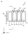
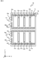
- FIG. 3 which is a cross-sectional view taken along the line III-III in FIG. 2
- FIG. 4 which is a cross-sectional view taken along the line IV-IV in FIG. and a heat transfer member 22a that internally disperses heat received from the capacitor elements 21a, 21b, 21c, 21d, 31a, 31b, 31c, and 31d, , 22b, 22c, 32a, 32b, 32c.
- the internal temperature of the capacitor unit 11 is the temperature of each of the capacitor elements 21a, 21b, 21c, 21d, 31a, 31b, 31c, and 31d.
- the vertical direction is the Z-axis direction
- the direction in which the capacitor elements 21a, 21b, 21c, and 21d are arranged is the X-axis direction.
- the X, Y, and Z axes are orthogonal to each other.
- the capacitor unit 11 further includes a first conductor 23a that is electrically connected to the positive electrodes of each of the capacitor elements 21a, 21b, 21c, and 21d, and a first conductor 23a that is electrically connected to the positive electrode of each of the capacitor elements 31a, 31b, 31c, and 31d. and a first conductor 33a.
- the first conductors 23a and 33a are, for example, bus bars made of a conductor such as copper or aluminum.
- the capacitor unit 11 further includes a second conductor 23b that is electrically connected to the negative electrodes of each of the capacitor elements 21a, 21b, 21c, and 21d, and a second conductor 23b that is electrically connected to the negative electrode of each of the capacitor elements 31a, 31b, 31c, and 31d. and a second conductor 33b.
- the second conductors 23b and 33b are bus bars made of a conductor such as copper or aluminum, for example.
- the capacitor unit 11 further includes a first terminal 24a electrically connected to the first conductor 23a, a first terminal 34a electrically connected to the first conductor 33a, and a first terminal 34a electrically connected to the second conductor 23b. and a second terminal 34b electrically connected to the second conductor 33b.
- the capacitor unit 11 further includes an insulating member 25 that covers a portion of each of the heat transfer members 22a, 22b, 22c, 32a, 32b, 32c and the entirety of the capacitor elements 21a, 21b, 21c, 21d, 31a, 31b, 31c, 31d. Equipped with The insulating member 25 is connected to the heat transfer members 22a, 22b, 22c with the respective ends 221a, 221b, 221c, 321a, 321b, 321c of the heat transfer members 22a, 22b, 22c, 32a, 32b, 32c exposed. , 32a, 32b, and 32c.
- the heat transfer members 22a, 22b, 22c, 32a, 32b, 32c included in the capacitor unit 11 described above include exposed ends 221a, 221b, 221c, 321a, 321b, and 321c. As a result, separation of the heat transfer members 22a, 22b, 22c, 32a, 32b, and 32c from the insulating member 25 is suppressed.
- the capacitor elements 21a, 21b, 21c, and 21d are arranged in a line with intervals between them. Specifically, the capacitor elements 21a, 21b, 21c, and 21d are arranged side by side in the X-axis direction, with the main surfaces of the exterior facing perpendicular to the X-axis. Similarly, capacitor elements 31a, 31b, 31c, and 31d are arranged side by side and spaced apart from each other. Specifically, the capacitor elements 31a, 31b, 31c, and 31d are arranged side by side in the X-axis direction, with the main surfaces of the exterior facing perpendicular to the X-axis.
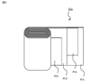
- the capacitor element 21a is a film capacitor, and includes a film 41c on which a positive electrode 41a is formed, and a film 41d on which a negative electrode 41b is formed. Films 41c and 41d are overlapped and wound around the central axis.
- the film 41c is a plastic film, and the positive electrode 41a is formed by depositing a metal such as aluminum or zinc onto the film 41c.
- the film 41d is a plastic film, and the negative electrode 41b is formed by depositing a metal such as aluminum or zinc onto the film 41d.
- One end of the capacitor element 21a in the direction of the central axis corresponds to a positive terminal, and the other end corresponds to a negative terminal.
- the upper end of the capacitor element 21a corresponds to the positive terminal
- the lower end of the capacitor element 21a corresponds to the negative terminal.
- the capacitor element 21a has an oval outer shape in a cross section perpendicular to the central axis.
- An ellipse means an external shape obtained by connecting the outer edges of two circles with the same diameter with two straight lines of the same length.
- the capacitor element 21a is provided with its central axis aligned with the Z-axis direction. Specifically, as shown in FIGS.
- the upper end of the capacitor element 21a in the Z-axis direction corresponds to the positive terminal of the capacitor element 21a
- the lower end of the capacitor element 21a in the Z-axis direction corresponds to the negative terminal of the capacitor element 21a. do.
- the heat transfer members 22a, 22b, 22c, 32a, 32b, 32c are provided at a position adjacent to at least one of the capacitor elements 21a, 21b, 21c, 21d, 31a, 31b, 31c, 31d.
- the heat transferred from at least one of 21b, 21c, 21d, 31a, 31b, 31c, and 31d is dispersed internally.
- the heat transfer members 22a, 22b, 22c, 32a, 32b, 32c are connected to the capacitor elements 21a, 21b, 21c. , 21d, 31a, 31b, 31c, and 31d, the capacitor elements are preferably provided between two adjacent capacitor elements.
- the heat transfer members 22a, 22b, 22c, 32a, 32b, 32c are located adjacent to different capacitor elements among the capacitor elements 21a, 21b, 21c, 21d, 31a, 31b, 31c, 31d. established in
- the heat transfer member 22a is provided between the capacitor elements 21a and 21b, and internally disperses the heat received from the capacitor elements 21a and 21b.
- the heat transfer member 22b is provided between the capacitor elements 21b and 21c, and internally disperses the heat received from the capacitor elements 21b and 21c.
- the heat transfer member 22c is provided between the capacitor elements 21c and 21d, and internally disperses the heat received from the capacitor elements 21c and 21d.
- the heat transfer member 32a is provided between the capacitor elements 31a and 31b, and internally disperses the heat received from the capacitor elements 31a and 31b.
- the heat transfer member 32b is provided between the capacitor elements 31b and 31c, and internally disperses the heat received from the capacitor elements 31b and 31c.
- the heat transfer member 32c is provided between the capacitor elements 31c and 31d, and internally disperses the heat received from the capacitor elements 31c and 31d.
- the heat transfer members 22a, 22b, 22c, 32a, 32b, and 32c are plate-shaped members in which at least one main surface abuts at least one of the capacitor elements 21a, 21b, 21c, 21d, 31a, 31b, 31c, and 31d. It is preferable that there be. Contacting includes direct contact and indirect contact.
- the heat transfer member 22a is a plate-like member, one main surface of the heat transfer member 22a contacts the capacitor element 21a, and the other main surface of the heat transfer member 22a contacts the capacitor element 21b.
- the heat transfer member 22b is a plate-shaped member, and one main surface of the heat transfer member 22b contacts the capacitor element 21b, and the other main surface of the heat transfer member 22b contacts the capacitor element 21c.
- the heat transfer member 22c is a plate-shaped member, and one main surface of the heat transfer member 22c contacts the capacitor element 21c, and the other main surface of the heat transfer member 22c contacts the capacitor element 21d.
- the heat transfer member 32a is a plate-like member, one main surface of the heat transfer member 32a contacts the capacitor element 31a, and the other main surface of the heat transfer member 32a contacts the capacitor element 31b.
- the heat transfer member 32b is a plate-shaped member, and one main surface of the heat transfer member 32b contacts the capacitor element 31b, and the other main surface of the heat transfer member 32b contacts the capacitor element 31c.
- the heat transfer member 32c is a plate-shaped member, and one main surface of the heat transfer member 32c contacts the capacitor element 31c, and the other main surface of the heat transfer member 32c contacts the capacitor element 31d.
- the heat transfer member 22a is a plate-like member that contacts the capacitor elements 21a, 21b with its surface, heat can be efficiently transferred from the capacitor elements 21a, 21b to the heat transfer member 22a.
- the heat transfer members 22a, 22b, 22c, 32a, 32b, and 32c are made of a material with high thermal conductivity, such as metal such as copper or aluminum, graphite, which is an anisotropic heat transfer member, or a different metal. It is preferably made of a clad material, a highly thermally conductive ceramic, or the like.
- the heat transfer efficiency from the capacitor elements 21a, 21b, 21c, 21d, 31a, 31b, 31c, and 31d to the outer surface of the capacitor unit 11 is improved.
- heat generated in the capacitor elements 21a, 21b, 21c, 21d, 31a, 31b, 31c, and 31d is efficiently transferred to the outside of the capacitor unit 11.
- the rise in temperature of capacitor elements 21a, 21b, 21c, 21d, 31a, 31b, 31c, and 31d is suppressed.
- the first conductor 23a is electrically connected to the positive electrode 41a of each of the capacitor elements 21a, 21b, 21c, and 21d by contacting the vertically upper ends of the capacitor elements 21a, 21b, 21c, and 21d.
- the first conductor 33a is electrically connected to the positive electrode 41a of each of the capacitor elements 31a, 31b, 31c, and 31d by contacting the vertically upper ends of the capacitor elements 31a, 31b, 31c, and 31d.
- the second conductor 23b is electrically connected to the negative electrode 41b of each of the capacitor elements 21a, 21b, 21c, and 21d by contacting the vertical lower ends of the capacitor elements 21a, 21b, 21c, and 21d.
- the second conductor 33b is electrically connected to the negative electrode 41b of each of the capacitor elements 31a, 31b, 31c, and 31d by contacting the vertical lower ends of the capacitor elements 31a, 31b, 31c, and 31d.
- the first terminal 24a is attached to the first conductor 23a with a fastening member (not shown) in contact with the first conductor 23a. As a result, the first terminal 24a is electrically connected to the first conductor 23a.
- the first terminal 34a is attached to the first conductor 33a with a fastening member (not shown) in contact with the first conductor 33a. As a result, the first terminal 34a is electrically connected to the first conductor 33a.
- the second terminal 24b is attached to the second conductor 23b with a fastening member (not shown) in contact with the second conductor 23b. As a result, the second terminal 24b is electrically connected to the second conductor 23b.
- the second terminal 34b is attached to the second conductor 33b with a fastening member (not shown) in contact with the second conductor 33b. As a result, the second terminal 34b is electrically connected to the second conductor 33b.
- the first capacitor C1 is realized by the above-mentioned capacitor elements 21a, 21b, 21c, 21d, first conductor 23a, second conductor 23b, first terminal 24a, and second terminal 24b.
- the first terminal 24a corresponds to the positive terminal of the first capacitor C1
- the second terminal 24b corresponds to the negative terminal of the first capacitor C1.
- the first terminal 24a is electrically connected to the terminal 1a and the primary terminal of the power converter 12 by a bus bar (not shown).
- the second terminal 24b is electrically connected to the primary terminal of the power converter 12 and the second capacitor C2 by a bus bar (not shown).
- a second capacitor C2 is realized by the above-described capacitor elements 31a, 31b, 31c, and 31d, the first conductor 33a, the second conductor 33b, the first terminal 34a, and the second terminal 34b.
- the first terminal 34a corresponds to the positive terminal of the second capacitor C2
- the second terminal 34b corresponds to the negative terminal of the second capacitor C2.
- the first terminal 34a is electrically connected to the primary terminal of the power converter 12 and the first capacitor C1 by a bus bar (not shown).
- the second terminal 34b is electrically connected to the terminal 1b and the primary terminal of the power converter 12 by a bus bar (not shown).
- the insulating member 25 is made of, for example, resin such as epoxy, urethane, and silicone.
- the insulating member 25 insulates the capacitor elements 21a, 21b, 21c, 21d, 31a, 31b, 31c, 31d and the heat transfer members 22a, 22b, 22c, 32a, 32b, 32c from each other.
- the insulating member 25 includes the heat transfer members 22a, 22b, 22c and the capacitor elements 21a, 21b, with the ends 221a, 221b, 221c of the heat transfer members 22a, 22b, 22c exposed. Covers 21c and 21d.
- the insulating member 25 is configured such that the heat transfer members 22a, 22b, 22c, which are plate-shaped members, have their ends 221a, 221b, 221c exposed in the Y-axis direction. Covers capacitor elements 21a, 21b, 21c, and 21d.
- the insulating member 25 further includes end portions 321a, 321b, 321c of the heat transfer members 32a, 32b, 32c, specifically Y of the heat transfer members 32a, 32b, 32c which are plate-shaped members.
- the heat transfer members 32a, 32b, 32c and the capacitor elements 31a, 31b, 31c, 31d are covered with the ends 321a, 321b, 321c in the axial direction exposed.
- the capacitor elements 21a, 21b, 21c, 21d, 31a, 31b, 31c, 31d, the heat transfer members 22a, 22b, 22c, 32a, 32b, 32c, the first conductors 23a, 33a, the second conductor 23b, 33b, the first terminals 24a, 34a, and the second terminals 24b, 34b are fixed in relative position.
- the insulating member 25 further connects the first conductors 23a, 33a, the second conductors 23b, 33b, and the It covers the first terminals 24a, 34a and the second terminals 24b, 34b. By exposing a portion of each of the first terminals 24a, 34a and a portion of each of the second terminals 24b, 34b, the bus bar is electrically connected to the first terminals 24a, 34a and the second terminals 24b, 34b. It becomes possible to connect.
- the above-described capacitor unit 11 can be obtained by arranging the components of the capacitor unit 11 other than the insulating member 25 inside a case (not shown), filling the case with epoxy resin, curing it, and taking it out from the case.
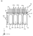
- the condenser unit 11 has exposed ends 221a, 221b, 221c of heat transfer members 22a, 22b, 22c and exposed heat transfer members 32a, 32b, 32c, as shown in FIG. It is preferable to further include a cooling section 26 that is thermally connected to the ends 321a, 321b, and 321c.
- the capacitor unit 11 further includes a TIM (Thermal Interface Material) 29 that contacts the surface of the insulating member 25 facing the cooling section 26 and the cooling section 26 to reduce contact thermal resistance.
- TIM Thermal Interface Material
- FIG. 6 is a diagram showing the capacitor unit 11 in the same cross section as FIG. 3.
- the cooling unit 26 directly contacts the exposed ends 221a, 221b, 221c of the heat transfer members 22a, 22b, 22c and the exposed ends 321a, 321b, 321c of the heat transfer members 32a, 32b, 32c. It has a heat receiving block 27 that comes into contact with it, and a heat radiator 28 that radiates the heat transferred from the heat receiving block 27.
- Heat transfer members 22a, 22b, 22c, 32a, 32b, and 32c are attached to one main surface 27a of the heat receiving block 27 by an attachment method such as fastening with a fastening member (not shown), bonding with an adhesive, brazing, welding, or the like.
- the heat radiator 28 is attached to the other main surface 27b of the heat receiving block 27 by an attachment method such as fastening with a fastening member (not shown), brazing, welding, or the like.
- the heat transfer member 22a is transferred from the capacitor elements 21a, 21b, 21c, 21d, 31a, 31b, 31c, 31d. , 22b, 22c, 32a, 32b, 32c, heat is transferred to the heat receiving block 27.
- the heat receiving block 27 is made of a material with high thermal conductivity, such as a metal such as copper or aluminum, graphite which is an anisotropic heat transport member, a cladding material made of different metals, or a highly thermally conductive ceramic. It is preferable that
- the heat receiving block 27 comes into contact with the end surfaces of the heat transfer members 22a, 22b, 22c, 32a, 32b, 32c, heat is directly transferred from the heat transfer members 22a, 22b, 22c, 32a, 32b, 32c to the heat receiving block 27. transferred, increasing heat transfer efficiency.
- the cooling performance of the capacitor elements 21a, 21b, 21c, 21d, 31a, 31b, 31c, 31d is improved, and the temperature increase of the capacitor elements 21a, 21b, 21c, 21d, 31a, 31b, 31c, 31d is suppressed. It becomes possible to suppress this.
- the heat radiator 28 radiates the heat transferred from the heat receiving block 27 to the surrounding air.
- the heat transferred from the capacitor elements 21a, 21b, 21c, 21d, 31a, 31b, 31c, 31d to the heat receiving block 27 via the heat transfer members 22a, 22b, 22c, 32a, 32b, 32c is transferred to the surroundings by the radiator 28. heat is radiated into the air.
- capacitor elements 21a, 21b, 21c, 21d, 31a, 31b, 31c, and 31d are cooled.
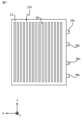
- the heat radiator 28 has a plurality of fins whose main surfaces are parallel to the YZ plane, as shown in FIGS. 6 and 7.
- the radiator 28 is made of a material with high thermal conductivity, such as metal such as copper or aluminum, graphite which is an anisotropic heat transport member, a cladding material made of different metals, or highly thermally conductive ceramic. It is preferable that
- the TIM 29 is formed of a heat dissipation sheet, grease, etc.
- the TIM 29 contacts the surface of the insulating member 25 facing the cooling section 26 and the main surface 27a of the heat receiving block 27, and covers the outer surfaces of the heat transfer members 22a, 22b, 22c, 32a, 32b, and 32c around the Y-axis direction.
- the TIM 29 allows heat to be efficiently transferred from the insulating member 25 to the heat receiving block 27 of the cooling unit 26.
- the electronic device 1 includes a housing 13 that houses the capacitor unit 11 and the power converter 12 having the above configuration.
- the description of the power conversion unit 12 is omitted in FIG. 8 .
- An opening 13a is formed in the housing 13.
- the cooling unit 26 of the condenser unit 11 closes the opening 13a with a portion exposed to the outside of the housing 13 through the opening 13a.
- air outside the housing 13 containing foreign substances such as dust and moisture is suppressed from flowing into the interior of the housing 13 through the opening 13a.
- the heat radiator 28 With the heat radiator 28 exposed to the outside of the housing 13, the heat receiving block 27 closes the opening 13a from inside the housing 13. Since the heat radiator 28 is exposed to the outside of the housing 13, the heat radiator 28 radiates the heat transferred from the heat receiving block 27 to the air outside the housing 13.
- capacitor elements 21a, 21b, 21c, 21d, 31a, 31b, 31c, and 31d are cooled. Since the temperature of the air outside the housing 13 is lower than the temperature of the air inside the housing 13, the cooling performance of the condenser unit 11 is higher than that of a condenser unit that radiates heat to the air inside the housing.
- the heat generated in the capacitor elements 21a, 21b, 21c, 21d, 31a, 31b, 31c, 31d is transferred to the heat receiving block 27 included in the cooling unit 26 via the heat transfer members 22a, 22b, 22c, 32a, 32b, 32c. be done.
- the heat transferred to the heat receiving block 27 is radiated to the air outside the casing 13 via the radiator 28 attached to the heat receiving block 27 or the casing 13 with which the heat receiving block 27 comes into contact.
- the capacitor elements 21a, 21b, 21c, 21d, 31a, 31b, 31c, and 31d are cooled, and the temperature rise of the capacitor elements 21a, 21b, 21c, 21d, 31a, 31b, 31c, and 31d is suppressed.
- the heat generated in the capacitor elements 21a, 21b, 21c, 21d, 31a, 31b, 31c, and 31d is radiated to the air outside the housing 13, so that the temperature of the air inside the housing 13 decreases.
- the rise is suppressed.
- an increase in the internal temperature of the capacitor unit 11 is suppressed.
- the capacitor elements 21a, 21b, 21c, 21d, 31a, 31b, 31c, 31d generate heat when energized and the temperature rises
- the capacitor elements 21a, 21b, 21c, 21d, 31a, 31b, 31c, 31d generate heat.
- the temperatures of the adjacent heat transfer members 22a, 22b, 22c, 32a, 32b, 32c and the insulating member 25 rise. Since the heat transfer members 22a, 22b, 22c, 32a, 32b, and 32c and the insulating member 25 are formed of different members, their linear expansion coefficients are different from each other.
- Thermal stress generated at the interface between the heat transfer members 22a, 22b, 22c, 32a, 32b, 32c and the insulating member 25 prevents the insulating member 25 from peeling off from the heat transfer members 22a, 22b, 22c, 32a, 32b, 32c.
- the structure for suppressing this will be explained below. Since the structures of the heat transfer members 22a, 22b, 22c, 32a, 32b, and 32c are the same, only the heat transfer member 22a will be described.
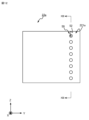
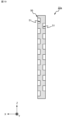
- FIG. 9 and FIG. 10 which is a cross-sectional view taken along line XX in FIG.
- the first peeling suppressing portion 50 is provided at least at a position adjacent to the end portion 221a.
- 9 and 10 are diagrams showing only the heat transfer member 22a among the components of the capacitor unit 11.
- the position adjacent to the end 221a may be a position sufficiently close to the end 221a, for example, in a range where the distance from one end of the end 221a on the Y-axis negative direction side is 30 mm or less.
- the first peeling suppressing portion 50 has at least one of a protruding shape and a recessed shape.
- the first peeling suppressing section 50 has a plurality of recesses 51 arranged in the Z-axis direction.
- Each recess 51 has a shape recessed from the outer surface of the heat transfer member 22a in the negative direction of the X-axis.
- the heat transfer member 22a is formed of a flat plate member having a width in the X-axis direction of 10 mm
- the length of the recess 51 in the X-axis direction is in the range of 2 mm or more and 3 mm or more. It is preferable.
- the plurality of recesses 51 are arranged side by side at intervals in the Z-axis direction.
- the recess 51 is filled with the insulating member 25, as shown in FIG. 11, which is a sectional view taken along the line XI-XI in FIG. As a result, the anchor effect prevents the insulating member 25 from peeling off from the heat transfer member 22a.
- the heat transfer member 22a has a polygonal shape with rounded corners in the direction from the exposed end 221a to the portion covered by the insulating member 25, that is, in a cross section perpendicular to the Y-axis direction. It is preferable. In the first embodiment, the heat transfer member 22a has a rectangular shape with rounded corners in the XZ plane.
- the first peeling suppressing portion 50 provided at a position adjacent to the end 221a of the heat transfer member 22a prevents the insulating member 25 from peeling off from the heat transfer member 22a, so that the insulating member 25 and the heat transfer member 22a The formation of voids between the two is suppressed. Therefore, moisture contained in the air outside the capacitor unit 11 moves along the end portion 221a, passes through the gap between the insulating member 25 and the heat transfer member 22a, and reaches the capacitor elements 21a and 21b. things are suppressed.
- the heat transfer members 22a, 22b, 22c included in the capacitor unit 11 according to the first embodiment are located at positions adjacent to the exposed ends 221a, 221b, 221c on the outer surface covered by the insulating member 25.
- the first peeling suppressing portion 50 is provided at least in the first peeling suppressing portion 50 .
- the heat transfer members 32a, 32b, 32c included in the capacitor unit 11 are provided with first peeling restraints provided at least at positions adjacent to the exposed ends 321a, 321b, 321c on the outer surface covered with the insulating member 25. 50.
- the first peeling suppressing portion 50 has at least one of a protruding shape and a recessed shape. The first peeling suppressing portion 50 suppresses peeling of the insulating member 25 from the heat transfer members 22a, 22b, 22c, 32a, 32b, and 32c.
- the amount of heat generated by the capacitor elements 21a, 21b, 21c, 21d, 31a, 31b, 31c, and 31d increases, and the heat transfer members 22a, 22b, 22c , 32a, 32b, 32c and the insulating member 25, even if the thermal stress generated at the interface increases, peeling of the insulating member 25 is suppressed. Therefore, a highly reliable capacitor unit 11 can be obtained in a high temperature environment.
- the peeling of the insulating member 25 is suppressed even when the heat generation amount of the capacitor elements 21a, 21b, 21c, 21d, 31a, 31b, 31c, and 31d increases, so the first peeling suppression is performed.
- the permissible temperature of the capacitor elements 21a, 21b, 21c, 21d, 31a, 31b, 31c, and 31d of the capacitor unit 11 is higher than that of a capacitor unit in which the portion 50 is not provided. In other words, it becomes possible to increase the voltage applied to the capacitor elements 21a, 21b, 21c, 21d, 31a, 31b, 31c, and 31d, or to make the films 41c and 41d thinner. Therefore, restrictions on the design of the capacitor unit 11 are relaxed.
- the capacity of the capacitor unit 11 can be increased by increasing the voltage applied to the capacitor elements 21a, 21b, 21c, 21d, 31a, 31b, 31c, and 31d.
- the capacitor elements 21a, 21b, 21c, 21d, 31a, 31b, 31c, and 31d that is, the capacitor unit 11 can be made smaller.
- the shape of the first peeling suppressing portion 50 is not limited to the above-mentioned example, and may be any shape as long as it can suppress the insulating member 25 from peeling off from the heat transfer members 22a, 22b, 22c, 32a, 32b, and 32c. .
- Heat transfer members 22a, 22b, 22c, 32a, 32b, and 32c each having a first peeling suppressing portion 50 having a shape different from that in Embodiment 1 will be described in Embodiment 2, focusing on the differences from Embodiment 1.
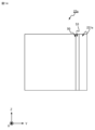
- FIGS. 13 is a sectional view taken in the direction of arrows.
- 12 and 13 are diagrams showing only the heat transfer member 22a among the components of the capacitor unit 11.
- the first peeling suppressing portion 50 is formed of a plurality of through holes 52 arranged in the Z-axis direction. Each through hole 52 penetrates the heat transfer member 22a in the X-axis direction.
- the through hole 52 is filled with the insulating member 25.
- the anchor effect prevents the insulating member 25 from peeling off from the heat transfer member 22a.
- the first peeling suppressing portion 50 of the heat transfer members 22a, 22b, 22c, 32a, 32b, and 32c included in the capacitor unit 11 according to the second embodiment is formed of a plurality of through holes 52.
- the through hole 52 By filling the through hole 52 with the insulating member 25, the insulating member 25 located on one main surface side of the heat transfer member 22a and the insulating member 25 located on the other main surface side of the heat transfer member 22a are separated. , are continuous via the insulating member 25 filled in each through hole 52. Therefore, peeling of the insulating member 25 from the heat transfer member 22a is more reliably suppressed than in the first embodiment. Similar effects can be obtained with the heat transfer members 22b, 22c, 32a, 32b, and 32c.
- the shape of the first peeling suppressing portion 50 is not limited to the above-mentioned example, and may be any shape as long as it can suppress the insulating member 25 from peeling off from the heat transfer members 22a, 22b, 22c, 32a, 32b, and 32c. .
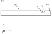
- Embodiment 3 focuses on the differences from Embodiments 1 and 2 regarding heat transfer members 22a, 22b, 22c, 32a, 32b, and 32c having first peeling suppressing portions 50 having shapes different from those of Embodiments 1 and 2. I will explain.
- the first peeling suppressing portion 50 is formed of a slit 53 extending in the Z-axis direction.
- the slit 53 is filled with the insulating member 25.
- the anchor effect prevents the insulating member 25 from peeling off from the heat transfer member 22a.
- the first peeling suppressing portions 50 of the heat transfer members 22a, 22b, 22c, 32a, 32b, and 32c included in the capacitor unit 11 according to the third embodiment are formed by the slits 53.
- the slit 53 By filling the slit 53 with the insulating member 25, peeling of the insulating member 25 from the heat transfer member 22a is suppressed over the entire Z-axis direction of the heat transfer member 22a. Therefore, peeling of the insulating member 25 from the heat transfer member 22a is more reliably suppressed than in the first embodiment. Similar effects can be obtained with the heat transfer members 22b, 22c, 32a, 32b, and 32c.
- the shape of the first peeling suppressing portion 50 is not limited to the above-mentioned example, and may be any shape as long as it can suppress the insulating member 25 from peeling off from the heat transfer members 22a, 22b, 22c, 32a, 32b, and 32c. .
- Embodiment 4 focuses on the differences from Embodiment 1-3 regarding heat transfer members 22a, 22b, 22c, 32a, 32b, and 32c having first peeling suppressing portions 50 having a shape different from Embodiment 1-3. I will explain.
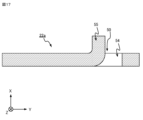
- the first peeling suppressing portion 50 provided in the heat transfer member 22a of the capacitor unit 11 according to the fourth embodiment has a protruding shape and a recessed shape.
- FIG. 16 and FIG. 17, which is a cross-sectional view taken along the line XVII-XVII in FIG. It has a convex portion 55 formed at an adjacent position.
- 16 and 17 are diagrams showing only the heat transfer member 22a among the components of the capacitor unit 11.
- the concave portion 54 and the convex portion 55 are formed by making a cut in the heat transfer member 22a and pulling out a part of the heat transfer member 22a in the X-axis direction.
- the insulating member 25 When the insulating member 25 is filled around the heat transfer member 22a, the insulating member 25 is filled into the recess 54 formed by the through hole. As a result, the anchor effect prevents the insulating member 25 from peeling off from the heat transfer member 22a.
- the convex portion 55 on the Y-axis negative direction side of the concave portion 54 moisture contained in the air outside the capacitor unit 11 is suppressed from moving in the Y-axis negative direction along the heat transfer member 22a. Ru.
- the first peeling suppressing portion 50 included in the heat transfer members 22a, 22b, 22c, 32a, 32b, and 32c included in the capacitor unit 11 according to the fourth embodiment includes the recess 54 and the projection 55. Filling the recess 54 with the insulating member 25 prevents the insulating member 25 from peeling off from the heat transfer member 22a. By providing the convex portion 55, even if a gap is created between the heat transfer member 22a and the insulating member 25, moisture contained in the air outside the capacitor unit 11 moves along the heat transfer member 22a. However, it is suppressed from reaching the capacitor elements 21a and 21b through the gap between the insulating member 25 and the heat transfer member 22a.
- the structure that suppresses peeling of the insulating member 25 from the heat transfer members 22a, 22b, 22c, 32a, 32b, and 32c is not limited to the first peeling suppressing portion 50.
- a capacitor unit that suppresses peeling of the insulating member 25 with a structure different from that of the first peeling suppressing section 50 will be described in a fifth embodiment, focusing on the differences from the first embodiment.
- the capacitor unit 61 shown in FIG. 18 includes covering members 62a, 62b, which cover the outer surfaces of the heat transfer members 22a, 22b, 22c, with the ends 221a, 221b, 221c of the heat transfer members 22a, 22b, 22c exposed. 62c. In the capacitor unit 61, the heat transfer members 22a, 22b, 22c do not have the first peeling suppressing portion 50.
- the capacitor unit 61 further includes covering members 62a, 62b that cover the outer surfaces of the heat transfer members 32a, 32b, 32c with the ends 321a, 321b, 321c of the heat transfer members 32a, 32b, 32c exposed. , 62c.
- the heat transfer members 32a, 32b, and 32c do not have the first peeling suppressing portion 50.
- the heat transfer member 22a and the heat transfer member 22a are covered.
- the covering member 62a will be explained.
- the heat transfer member 22a is covered with a covering member 62a with the end portion 221a exposed.
- the covering member 62a is a member whose linear expansion coefficient is smaller than the linear expansion coefficient of the heat transfer member 22a and larger than the linear expansion coefficient of the insulating member 25, or a member whose linear expansion coefficient is larger than the linear expansion coefficient of the heat transfer member 22a, In addition, it is formed of a member having a linear expansion coefficient smaller than that of the insulating member 25. In other words, the linear expansion coefficient of the covering member 62a is smaller than the linear expansion coefficient of the heat transfer member 22a and larger than the linear expansion coefficient of the insulating member 25, or larger than the linear expansion coefficient of the heat transfer member 22a, and , is smaller than the linear expansion coefficient of the insulating member 25.
- both the thermal stress at the interface between the heat transfer member 22a and the covering member 62a and the thermal stress at the interface between the covering member 62a and the insulating member 25 are the same as those at the interface between the heat transfer member 22a and the insulating member 25 in Embodiment 1-4. smaller than the thermal stress at the interface with The same applies to the heat transfer members 22b, 22c, 32a, 32b, and 32c.
- the heat transfer member 22a may be formed of magnesium, the covering member 62a may be formed of polyethylene, and the insulating member 25 may be formed of epoxy resin. At this time, the linear expansion coefficient of the covering member 62a is smaller than the linear expansion coefficient of the heat transfer member 22a and larger than the linear expansion coefficient of the insulating member 25.
- the heat transfer member may be made of carbon steel, the covering member 62a may be made of fluororesin, and the insulating member 25 may be made of high-density polyethylene.
- the capacitor unit 61 includes the covering members 62a, 62b, 62c covering the heat transfer members 22a, 22b, 22c, the covering members 62a, 62b covering the heat transfer members 32a, 32b, 32c, 62c.
- the thermal stress at the interface between heat transfer member 22a and covering member 62a and the thermal stress at the interface between covering member 62a and insulating member 25 are both the same as those at the interface between heat transfer member 22a and insulating member 25 in Embodiment 1-4. less than the thermal stress at Therefore, separation of the insulating member 25 from the heat transfer members 22a, 22b, 22c, 32a, 32b, and 32c is suppressed.
- the capacitor unit 61 may include the heat transfer members 22a, 22b, 22c, 32a, 32b, and 32c included in the capacitor unit 11 according to Embodiment 1-4.
- the heat transfer members 22a, 22b, 22c, 32a, 32b, and 32c may be formed of heat pipes.
- the first peeling suppressing part 50 is formed with a recess 51 or a slit 53 that does not penetrate the wall surface of the heat pipe.
- the shape of the first peeling suppressing part 50 is arbitrary as long as it can suppress peeling of the insulating member 25 from the heat transfer members 22a, 22b, 22c, 32a, 32b, and 32c.
- the first peeling suppressing portion 50 may be formed by roughening the surfaces of the heat transfer members 22a, 22b, 22c, 32a, 32b, and 32c by filing them.
- the first peeling suppressing portion 50 may be formed by etching the surfaces of the heat transfer members 22a, 22b, 22c, 32a, 32b, and 32c to form irregularities.
- the first peeling suppressing portion 50 may be formed by a narrow portion having a cross-sectional area perpendicular to the Y-axis direction that is narrower than other portions.
- the through hole 52 is a through hole that extends from the surface of the heat transfer member 22a facing in the X-axis positive direction to the surface facing in the X-axis negative direction, and extends in a direction intersecting the X-axis. may be formed.
- the through holes 52 may be formed in multiple rows.
- the location where the first peeling suppressing portion 50 is provided is not limited to the above-mentioned example, and the exposed ends 221a, 221b, 221c of the heat transfer members 22a, 22b, 22c and the exposure of the heat transfer members 32a, 32b, 32c Any location may be used as long as it includes positions adjacent to the ends 321a, 321b, and 321c.
- the first peeling suppressing portion 50 may be provided over the entire surface of the heat transfer members 22a, 22b, 22c, 32a, 32b, and 32c.
- recesses 51 may be provided on both the surface facing the X-axis positive direction and the surface facing the X-axis negative direction of the heat transfer member 22a.
- slits 53 may be formed on both the surface facing the X-axis positive direction and the surface facing the X-axis negative direction of the heat transfer member 22a.
- convex portions 55 protruding in the positive direction of the X-axis and convex portions 55 protruding in the negative direction of the X-axis are arranged alternately in the Z-axis direction. Good too.
- the shape of the insulating member 25 is not limited to the above example.
- slits 25a may be formed on the surface of the insulating member 25 facing the cooling section 26. By forming the slits 25a, thermal stress applied to the insulating member 25 is reduced.
- the capacitor units 11 and 61 may further include a structure that prevents the insulating member 25 from peeling off from the components of the capacitor unit 11 other than the heat transfer members 22a, 22b, 22c, 32a, 32b, and 32c.
- FIG. 23 and FIG. 24 which is a cross-sectional view taken along the line XXIV-XXIV in FIG. It may have a second peeling suppressing part 70 that suppresses peeling.
- the first conductors 23a, 33a and the second conductors 23b, 33b have a second It has a peeling suppressing part 70.
- the second peeling suppressing portion 70 is formed of a plurality of recesses 71 recessed in the Z-axis direction. By providing the second peeling suppressing portion 70, it is suppressed that the insulating member 25 is peeled off from the first conductors 23a, 33a and the second conductors 23b, 33b and a gap is generated. As a result, moisture contained in the air outside the capacitor unit 11 passes through the gaps between the insulating member 25 and the first conductors 23a, 33a and the second conductors 23b, 33b, and the capacitor elements 21a, 21b, 21c, 21d, 31a, 31b, 31c, and 31d are suppressed.
- the shape of the second peeling suppressing portion 70 is not limited to the above example.
- the second peeling suppressing portion 70 may be formed with a slit.
- the second peeling suppressing portion 70 may be formed of a recess and a projection that are adjacent to each other.
- the number of capacitor elements 21a, 21b, 21c, 21d, 31a, 31b, 31c, and 31d included in the capacitor units 11 and 61 is not limited to the above example, but is arbitrary.
- the capacitor unit 11 has two capacitor groups, the first capacitor C1 and the second capacitor C2, but the number of capacitor groups is arbitrary.
- the capacitor unit may include only the first capacitor C1, or may include a third capacitor in addition to the first capacitor C1 and the second capacitor C2.
- the configurations of the capacitor elements 21a, 21b, 21c, 21d, 31a, 31b, 31c, and 31d are not limited to the above example.
- the capacitor elements 21a, 21b, 21c, 21d, 31a, 31b, 31c, and 31d may be film capacitors using metal foil.
- the number and shape of the heat transfer members 22a, 22b, 22c, 32a, 32b, and 32c are such that the heat generated in the capacitor elements 21a, 21b, 21c, 21d, 31a, 31b, 31c, and 31d can be internally dispersed. If so, it is optional.
- the heat transfer members 22a, 22b, 22c, 32a, 32b, and 32c may be formed of rod-shaped members.
- the heat transfer members 22a, 22b, 22c, 32a, 32b, and 32c may be plate-shaped members bent in a U-shape, or rod-shaped members bent in a U-shape.
- the heat transfer members 22a, 22b, 22c, 32a, 32b, and 32c may be plate-shaped members in which a refrigerant is sealed in a flow path formed inside.
- the heat transfer members 22a, 22b, 22c, 32a, 32b, and 32c are not limited to the above example.
- the heat transfer member may be provided at a position adjacent only to the capacitor element 21d, specifically, at a position adjacent to the surface of the capacitor element 21d facing in the positive direction of the X-axis.
- a heat transfer member may be provided between the first conductor 23a and the surface of the capacitor element 21a facing in the negative direction of the X-axis.
- the shape of the heat radiator 28 is arbitrary as long as it can radiate the heat transferred from the heat receiving block 27.
- the plurality of fins that the radiator 28 has can be arbitrarily changed depending on the flow of air near the radiator 28.
- the heat radiator 28 may have a plurality of rod-shaped protrusions.
- the radiator 28 may have a heat pipe, or may have a plate-like member in which a refrigerant is sealed in a flow path formed inside.
- the position where the cooling unit 26 is provided is not limited to the above example. Specifically, the cooling unit 26 may be provided inside the housing 13 instead of outside the housing 13. In this case, the cooling unit 26 is preferably provided inside the casing 13 at a position into which air from outside the casing 13 flows.
- the method of attaching the insulating member 25 to the heat receiving block 27 is arbitrary.
- the insulating member 25 may be attached to the heat receiving block 27 by an attachment method such as fastening with a fastening member or bonding with an adhesive.
- the electronic device 1 is not limited to a three-level power converter, but is any device including the capacitor unit 11. As an example, the electronic device 1 may be a rectifier.
- the electronic device 1 is not limited to a railway vehicle, and can be mounted on any moving object such as an automobile, a ship, or an aircraft.
- the load 91 is not limited to a three-phase induction motor, but is any device that receives power supply from the electronic device 1.
- the load 91 is an air conditioner, a lighting device, or the like.
Landscapes
- Engineering & Computer Science (AREA)
- Power Engineering (AREA)
- Microelectronics & Electronic Packaging (AREA)
- Manufacturing & Machinery (AREA)
- Fixed Capacitors And Capacitor Manufacturing Machines (AREA)
Priority Applications (2)
| Application Number | Priority Date | Filing Date | Title |
|---|---|---|---|
| PCT/JP2022/018551 WO2023203754A1 (ja) | 2022-04-22 | 2022-04-22 | コンデンサユニットおよび電子機器 |
| JP2024516036A JP7607829B2 (ja) | 2022-04-22 | 2022-04-22 | コンデンサユニットおよび電子機器 |
Applications Claiming Priority (1)
| Application Number | Priority Date | Filing Date | Title |
|---|---|---|---|
| PCT/JP2022/018551 WO2023203754A1 (ja) | 2022-04-22 | 2022-04-22 | コンデンサユニットおよび電子機器 |
Publications (1)
| Publication Number | Publication Date |
|---|---|
| WO2023203754A1 true WO2023203754A1 (ja) | 2023-10-26 |
Family
ID=88419455
Family Applications (1)
| Application Number | Title | Priority Date | Filing Date |
|---|---|---|---|
| PCT/JP2022/018551 Ceased WO2023203754A1 (ja) | 2022-04-22 | 2022-04-22 | コンデンサユニットおよび電子機器 |
Country Status (2)
| Country | Link |
|---|---|
| JP (1) | JP7607829B2 (https=) |
| WO (1) | WO2023203754A1 (https=) |
Cited By (1)
| Publication number | Priority date | Publication date | Assignee | Title |
|---|---|---|---|---|
| WO2025126705A1 (ja) * | 2023-12-12 | 2025-06-19 | 株式会社村田製作所 | コンデンサモジュール |
Citations (12)
| Publication number | Priority date | Publication date | Assignee | Title |
|---|---|---|---|---|
| JPS5575160U (https=) * | 1978-11-20 | 1980-05-23 | ||
| JPS645043A (en) * | 1987-06-29 | 1989-01-10 | Shinko Electric Ind Co | Semiconductor device |
| JPH05326750A (ja) * | 1992-05-19 | 1993-12-10 | Hitachi Cable Ltd | 樹脂封止型半導体装置 |
| JPH09153571A (ja) * | 1995-11-30 | 1997-06-10 | Mitsubishi Electric Corp | 半導体装置 |
| JPH09260180A (ja) * | 1996-03-19 | 1997-10-03 | Shizuki Denki Seisakusho:Kk | 低インダクタンスコンデンサ |
| JP2000049271A (ja) * | 1998-07-31 | 2000-02-18 | Mitsubishi Electric Corp | 半導体装置 |
| JP2006165158A (ja) * | 2004-12-06 | 2006-06-22 | Matsushita Electric Ind Co Ltd | 電子部品 |
| JP2008071934A (ja) * | 2006-09-14 | 2008-03-27 | Fujitsu Ltd | 半導体装置およびその製造方法 |
| JP2009194080A (ja) * | 2008-02-13 | 2009-08-27 | Daikin Ind Ltd | コンデンサモジュール |
| JP2013191805A (ja) * | 2012-03-15 | 2013-09-26 | Kojima Press Industry Co Ltd | 樹脂モールド型コンデンサ |
| JP2014220362A (ja) * | 2013-05-08 | 2014-11-20 | トヨタ自動車株式会社 | コンデンサモジュール |
| JP2015138880A (ja) * | 2014-01-22 | 2015-07-30 | 株式会社指月電機製作所 | コンデンサ及びコンデンサの設置方法 |
-
2022
- 2022-04-22 JP JP2024516036A patent/JP7607829B2/ja active Active
- 2022-04-22 WO PCT/JP2022/018551 patent/WO2023203754A1/ja not_active Ceased
Patent Citations (12)
| Publication number | Priority date | Publication date | Assignee | Title |
|---|---|---|---|---|
| JPS5575160U (https=) * | 1978-11-20 | 1980-05-23 | ||
| JPS645043A (en) * | 1987-06-29 | 1989-01-10 | Shinko Electric Ind Co | Semiconductor device |
| JPH05326750A (ja) * | 1992-05-19 | 1993-12-10 | Hitachi Cable Ltd | 樹脂封止型半導体装置 |
| JPH09153571A (ja) * | 1995-11-30 | 1997-06-10 | Mitsubishi Electric Corp | 半導体装置 |
| JPH09260180A (ja) * | 1996-03-19 | 1997-10-03 | Shizuki Denki Seisakusho:Kk | 低インダクタンスコンデンサ |
| JP2000049271A (ja) * | 1998-07-31 | 2000-02-18 | Mitsubishi Electric Corp | 半導体装置 |
| JP2006165158A (ja) * | 2004-12-06 | 2006-06-22 | Matsushita Electric Ind Co Ltd | 電子部品 |
| JP2008071934A (ja) * | 2006-09-14 | 2008-03-27 | Fujitsu Ltd | 半導体装置およびその製造方法 |
| JP2009194080A (ja) * | 2008-02-13 | 2009-08-27 | Daikin Ind Ltd | コンデンサモジュール |
| JP2013191805A (ja) * | 2012-03-15 | 2013-09-26 | Kojima Press Industry Co Ltd | 樹脂モールド型コンデンサ |
| JP2014220362A (ja) * | 2013-05-08 | 2014-11-20 | トヨタ自動車株式会社 | コンデンサモジュール |
| JP2015138880A (ja) * | 2014-01-22 | 2015-07-30 | 株式会社指月電機製作所 | コンデンサ及びコンデンサの設置方法 |
Cited By (1)
| Publication number | Priority date | Publication date | Assignee | Title |
|---|---|---|---|---|
| WO2025126705A1 (ja) * | 2023-12-12 | 2025-06-19 | 株式会社村田製作所 | コンデンサモジュール |
Also Published As
| Publication number | Publication date |
|---|---|
| JP7607829B2 (ja) | 2024-12-27 |
| JPWO2023203754A1 (https=) | 2023-10-26 |
Similar Documents
| Publication | Publication Date | Title |
|---|---|---|
| US6740968B2 (en) | Power source unit for driving magnetron and heatsink to be mounted on printed circuit board thereof | |
| JP7373915B2 (ja) | 電力変換装置 | |
| JP5217884B2 (ja) | 半導体装置 | |
| US11464141B2 (en) | Power converter device for a vehicle, and vehicle | |
| US9992915B2 (en) | Power conversion device | |
| US12249922B2 (en) | Power conversion device | |
| CN114079390B (zh) | 功率转换装置 | |
| JP5664472B2 (ja) | 電力変換装置 | |
| US12143026B2 (en) | Power conversion device | |
| CN111971886A (zh) | 电力转换装置 | |
| WO2021053975A1 (ja) | 電力変換装置およびモータ一体型電力変換装置 | |
| JP2023024493A (ja) | 電力変換装置および電力変換装置の製造方法 | |
| US12133369B2 (en) | Power conversion device | |
| JP5101971B2 (ja) | 半導体装置 | |
| WO2023203754A1 (ja) | コンデンサユニットおよび電子機器 | |
| JP6647350B2 (ja) | 電力変換装置 | |
| JP7504294B2 (ja) | 電子機器 | |
| JP5621812B2 (ja) | 半導体装置 | |
| US20250096696A1 (en) | Power conversion apparatus | |
| EP4318922B1 (en) | Power module | |
| CN117730630A (zh) | 电压转换系统和用于制造这种电压转换系统的方法 | |
| CN117616885A (zh) | 电压转换系统和用于制造这种电压转换系统的方法 | |
| WO2022264297A1 (ja) | 電子機器 |
Legal Events
| Date | Code | Title | Description |
|---|---|---|---|
| 121 | Ep: the epo has been informed by wipo that ep was designated in this application |
Ref document number: 22938553 Country of ref document: EP Kind code of ref document: A1 |
|
| ENP | Entry into the national phase |
Ref document number: 2024516036 Country of ref document: JP Kind code of ref document: A |
|
| NENP | Non-entry into the national phase |
Ref country code: DE |
|
| 122 | Ep: pct application non-entry in european phase |
Ref document number: 22938553 Country of ref document: EP Kind code of ref document: A1 |