WO2023199657A1 - 負極バインダー組成物およびその製造方法、負極、及び二次電池 - Google Patents
負極バインダー組成物およびその製造方法、負極、及び二次電池 Download PDFInfo
- Publication number
- WO2023199657A1 WO2023199657A1 PCT/JP2023/008947 JP2023008947W WO2023199657A1 WO 2023199657 A1 WO2023199657 A1 WO 2023199657A1 JP 2023008947 W JP2023008947 W JP 2023008947W WO 2023199657 A1 WO2023199657 A1 WO 2023199657A1
- Authority
- WO
- WIPO (PCT)
- Prior art keywords
- negative electrode
- weight
- water
- parts
- binder composition
- Prior art date
- Legal status (The legal status is an assumption and is not a legal conclusion. Google has not performed a legal analysis and makes no representation as to the accuracy of the status listed.)
- Ceased
Links
Classifications
-
- H—ELECTRICITY
- H01—ELECTRIC ELEMENTS
- H01M—PROCESSES OR MEANS, e.g. BATTERIES, FOR THE DIRECT CONVERSION OF CHEMICAL ENERGY INTO ELECTRICAL ENERGY
- H01M4/00—Electrodes
- H01M4/02—Electrodes composed of, or comprising, active material
- H01M4/13—Electrodes for accumulators with non-aqueous electrolyte, e.g. for lithium-accumulators; Processes of manufacture thereof
- H01M4/133—Electrodes based on carbonaceous material, e.g. graphite-intercalation compounds or CFx
-
- H—ELECTRICITY
- H01—ELECTRIC ELEMENTS
- H01M—PROCESSES OR MEANS, e.g. BATTERIES, FOR THE DIRECT CONVERSION OF CHEMICAL ENERGY INTO ELECTRICAL ENERGY
- H01M4/00—Electrodes
- H01M4/02—Electrodes composed of, or comprising, active material
- H01M4/36—Selection of substances as active materials, active masses, active liquids
-
- H—ELECTRICITY
- H01—ELECTRIC ELEMENTS
- H01M—PROCESSES OR MEANS, e.g. BATTERIES, FOR THE DIRECT CONVERSION OF CHEMICAL ENERGY INTO ELECTRICAL ENERGY
- H01M4/00—Electrodes
- H01M4/02—Electrodes composed of, or comprising, active material
- H01M4/36—Selection of substances as active materials, active masses, active liquids
- H01M4/48—Selection of substances as active materials, active masses, active liquids of inorganic oxides or hydroxides
-
- H—ELECTRICITY
- H01—ELECTRIC ELEMENTS
- H01M—PROCESSES OR MEANS, e.g. BATTERIES, FOR THE DIRECT CONVERSION OF CHEMICAL ENERGY INTO ELECTRICAL ENERGY
- H01M4/00—Electrodes
- H01M4/02—Electrodes composed of, or comprising, active material
- H01M4/36—Selection of substances as active materials, active masses, active liquids
- H01M4/58—Selection of substances as active materials, active masses, active liquids of inorganic compounds other than oxides or hydroxides, e.g. sulfides, selenides, tellurides, halogenides or LiCoFy; of polyanionic structures, e.g. phosphates, silicates or borates
- H01M4/583—Carbonaceous material, e.g. graphite-intercalation compounds or CFx
- H01M4/587—Carbonaceous material, e.g. graphite-intercalation compounds or CFx for inserting or intercalating light metals
-
- H—ELECTRICITY
- H01—ELECTRIC ELEMENTS
- H01M—PROCESSES OR MEANS, e.g. BATTERIES, FOR THE DIRECT CONVERSION OF CHEMICAL ENERGY INTO ELECTRICAL ENERGY
- H01M4/00—Electrodes
- H01M4/02—Electrodes composed of, or comprising, active material
- H01M4/62—Selection of inactive substances as ingredients for active masses, e.g. binders, fillers
-
- Y—GENERAL TAGGING OF NEW TECHNOLOGICAL DEVELOPMENTS; GENERAL TAGGING OF CROSS-SECTIONAL TECHNOLOGIES SPANNING OVER SEVERAL SECTIONS OF THE IPC; TECHNICAL SUBJECTS COVERED BY FORMER USPC CROSS-REFERENCE ART COLLECTIONS [XRACs] AND DIGESTS
- Y02—TECHNOLOGIES OR APPLICATIONS FOR MITIGATION OR ADAPTATION AGAINST CLIMATE CHANGE
- Y02E—REDUCTION OF GREENHOUSE GAS [GHG] EMISSIONS, RELATED TO ENERGY GENERATION, TRANSMISSION OR DISTRIBUTION
- Y02E60/00—Enabling technologies; Technologies with a potential or indirect contribution to GHG emissions mitigation
- Y02E60/10—Energy storage using batteries
Definitions
- the present invention relates to a negative electrode binder composition, a method for producing the same, and a negative electrode and secondary battery containing the negative electrode binder composition.
- the binder in the negative electrode of a lithium ion secondary battery (hereinafter sometimes referred to as "LIB") is a water-soluble polymer carboxymethyl cellulose sodium salt (CMC) and an aqueous latex resin styrene-butadiene copolymer. Combined use of combination (SBR) is common.
- the main functions of the binder are: 1) to uniformly disperse components such as active materials and conductive aids during the electrode manufacturing process; 2) to adjust the rheology of the electrode mixture slurry; and 3) during the slurry application and drying. Examples include a leveling function to flatten the mixture layer, and 4) a function to bind the mixture components and the current collector.
- the functions related to battery performance include 5) a function to suppress electrode expansion due to volume changes of the active material that occur during charge/discharge cycles, and 6) a function to maintain binding between the active material and the current collector and improve electronic conductivity. and 7) a function of ensuring ionic conductivity by appropriately swelling with an electrolyte.
- LIB is widely used as a power source that can charge laptops, mobile phones, etc., but in recent years, its use has rapidly expanded in power tools such as electric tools, and medium- and large-sized equipment such as automobiles and stationary power storage equipment. are doing. With the rapid expansion of the range of applications, the performance required of batteries over a wider temperature range varies, but the three main performance points of importance are capacity, output, and lifespan, and improvements in these areas are particularly important. desired.
- new negative electrode active materials are being considered to replace the conventionally widely used carbon-based active materials (eg, graphite) in an effort to increase capacity.
- new negative electrode active materials include tin alloys, silicon alloys, silicon oxides, and the like. These new negative electrode active materials have extremely large capacities, several times as large as carbon-based active materials, and it is possible to increase the negative electrode capacity even by adding a small amount.
- the problem with these new negative electrode active materials is that they have a lower capacity retention rate during charge/discharge cycles than carbon-based active materials.
- the new negative electrode active material has a larger volumetric expansion and contraction during charging and discharging than a carbon-based active material, which can lead to loss of the active material and a decrease in electronic conductivity due to destruction of the electrode structure.
- the SEI film formed on the surface of the active material cannot follow the volume change and is destroyed, the surface of the active material not covered by the SEI film will be exposed, and the electrolyte will decompose due to a new SEI film formation reaction. It is also possible that the process progresses.
- the SEI film is mainly composed of decomposed electrolyte and is formed on the surface of the active material during the first charge.
- This SEI coating is thought to play a role in mediating the intercalation and deintercalation reactions of lithium ions, and at the same time suppresses further decomposition reactions of the electrolyte, contributing to improved battery performance. If the SEI film is too thin, the decomposition reaction of the electrolyte will not stop, and if it is too thick, the electrical resistance will increase, which will have a negative impact on the lifespan and efficiency of the battery.
- Patent Document 1 proposes a method of suppressing the volume change of the negative electrode active material by using a high-strength aromatic polyimide as a binder. has been done. Further, Patent Document 2 below proposes a method of suppressing volume change of a negative electrode active material by using partially crosslinked polyacrylic acid as a binder. Furthermore, Patent Document 3 below proposes a method of suppressing volume change of a negative electrode active material by using a copolymer of acrylic acid and polyvinyl alcohol as a binder. However, with the binder of Patent Document 1, the initial charge/discharge efficiency was poor and the capacity of the active material could not be fully demonstrated. Furthermore, the binders of Patent Documents 2 and 3 did not necessarily have sufficient high-temperature and low-temperature cycle characteristics.
- the conventional method of increasing capacity by increasing the weight of active material per unit area without changing the graphite-based negative electrode is used.
- either or both of an increase in the thickness of the electrode layer (thick film) and an increase in the electrode density (high density) are essential.
- the electrode becomes thicker the distance that electrons and ions move within the electrode increases, and therefore the resistance to their movement increases.
- the density is increased, the voids between the active material particles are reduced, so the flow path of the electrolytic solution becomes narrower, and the resistance to ion movement increases.
- An increase in resistance is a factor that causes a decrease in battery performance, leading to a decrease in capacity retention rate and load characteristics.
- Patent Document 4 As an effort to solve the problems of increasing the thickness and density of the electrode, for example, in Patent Document 4 listed below, the negative electrode is made into two layers, using CMC/SBR for the lower layer, and an acrylate binder with high electrolyte swelling property for the upper layer. A method using .
- the method of Patent Document 4 has the disadvantage that the electrode manufacturing process is doubled.
- the electrolyte swelling degree of the upper layer is large, there is a concern that cycle characteristics may deteriorate at high temperatures.
- Patent Document 5 proposes a method using a mixed resin of PVDF and a resin having an acidic functional group and a polyvinylidene fluoride skeleton as the main chain.
- an organic solvent such as NMP is used as a solvent for slurrying. From the viewpoint of cost etc., it is preferable to use an aqueous solvent for slurry formation.
- an object of the present invention is to provide a negative electrode binder composition that provides good battery performance even when using a new active material, thickening the electrode, and increasing the density, and a method for producing the same, including the negative electrode binder composition.
- the purpose of the present invention is to provide a negative electrode and a secondary battery.
- a negative electrode binder composition containing a water-soluble resin (X) containing a copolymer containing a hydroxyl group-containing monomer (a) and an acid group-containing monomer (b) as essential components, and a water-based latex resin (Y).
- the copolymer has a weight average molecular weight of 700,000 or more when measured using an aqueous GPC measuring device, and the dry film of the copolymer is heated in a carbonate-based mixed solvent (EC (ethylene) at 45°C).
- EC carbonate-based mixed solvent
- a negative electrode binder composition having a swelling ratio of 0 to 10% by weight after being immersed in diethylene carbonate (diethylene carbonate)/DEC (diethylene carbonate) 50/50 (wt) for 72 hours.
- the hydroxyl group-containing monomer (a) is 2-hydroxyethyl acrylate, 2-hydroxypropyl acrylate, 3-hydroxypropyl acrylate, 2-hydroxybutyl acrylate, 4-hydroxybutyl acrylate, 2-hydroxyethyl methacrylate, 2- The negative electrode binder composition according to [1], which is any one or more of the group consisting of hydroxypropyl methacrylate, 3-hydroxypropyl methacrylate, 2-hydroxybutyl methacrylate, and 4-hydroxybutyl methacrylate.
- the acid group-containing monomer (b) is any one of the group consisting of acrylic acid, methacrylic acid, maleic acid, monomethylmaleic acid, 2-carboxyethyl acrylate, 2-carboxyethyl methacrylate, maleic acid, and itaconic acid.
- the water-soluble resin (X) further contains any one or more of the group consisting of acrylamide, methacrylamide, N-methylacrylamide, N,N-dimethylacrylamide, and N-hydroxymethylacrylamide [1 ] to [4].
- the total content of the resin components derived from the hydroxyl group-containing monomer (a) and the acid group-containing monomer (b) with respect to the total amount of the water-soluble resin (X) is 5 to 80% by weight [1] to [ 5], the negative electrode binder composition according to any one of items 5] [7]
- the content of any one or more of the group consisting of acrylamide, methacrylamide, N-methylacrylamide, N,N-dimethylacrylamide, and N-hydroxymethylacrylamide is 0 to 80% by weight [ 1] to [6].
- the content of structural units derived from styrene monomer is 40 to 60% by weight, and the content of structural units derived from butyl acrylate monomer is 20 to 40% by weight in the total amount of the styrene acrylate copolymer.
- a negative electrode comprising the negative electrode binder composition according to any one of [1] to [10] as a component.
- the negative electrode according to [11] wherein the total content of the component derived from the water-soluble resin (X) and the component derived from the water-based latex resin (Y) is 1.5% by weight or more and 5.5% by weight or less. .
- a secondary battery comprising the negative electrode according to any one of [11] to [15].
- the method includes a step of hardening an aqueous slurry consisting of at least an active material and the water-soluble resin (X), and then a step of lowering the solid content concentration and mixing the aqueous latex resin (Y) [1] The method for producing a negative electrode binder composition according to any one of [10].
- the negative electrode binder composition of the present invention has good slurry stability even without a thickener such as cellulose, and when formed into a film, it also has good electrolyte swelling resistance at high temperatures. Therefore, the negative electrode containing the negative electrode binder composition of the present invention as a component has strong peel strength, and as a result, when battery evaluation is performed, it exhibits good charge/discharge characteristics even at a high number of cycles, and is suitable for recent LIB negative electrodes. The required performance can be achieved.
- the negative electrode binder composition of the present invention comprises a water-soluble resin (X) containing a copolymer containing a hydroxyl group-containing monomer (a) and an acid group-containing monomer (b) as essential components, and a water-based latex resin (Y).
- the weight average molecular weight of the copolymer measured using an aqueous GPC measuring device is 700,000 or more, preferably 750,000 to 1,500,000, more preferably 800,000 to 1, 200,000.
- the weight average molecular weight is 700,000 or more, as described above in the effects of the invention, the slurry stability is good, and when this is used as a film, the electrolyte swelling resistance at high temperatures is also good.
- a common polymer-based filler such as polyhydroxymethacrylate can be used as a column filler.
- the column for example, SB-806 HQ, SB-806M HQ of the Shodex OHpak series manufactured by Showa Denko K.K. can be used.
- a neutral salt solution such as a sodium nitrate aqueous solution, a sodium hydrogen hydrochloride aqueous solution, a sodium sulfate aqueous solution, a phosphate buffer, etc. can be used.
- concentration of these eluents is preferably about 0.1 to 0.3 mol/L, for example.
- GPC measurement device a Shimadzu/L20 system or the like can be used.
- Polystyrene or pullulan can be used as a standard substance in GPC measurement.
- STANDARD P-82 Pullulan manufactured by Showa Denko K.K. can be used as a standard substance.
- the swelling ratio after the dry polymer film of the negative electrode binder composition is immersed in a carbonate mixed solvent at 45°C for 72 hours is 0 to 10% by weight, but the swelling ratio is preferably 0.1 to 10% by weight. 6% by weight, more preferably 0.1 to 4% by weight.
- a high swelling rate means that the negative electrode binder composition tends to contain a solvent, and when used as a negative electrode, the mixture tends to peel off from a base material such as copper.
- Examples of the hydroxyl group-containing monomer (a) in the above copolymer include 2-hydroxyethyl acrylate, 2-hydroxypropyl acrylate, 3-hydroxypropyl acrylate, 2-hydroxybutyl acrylate, 4-hydroxybutyl acrylate, and 2-hydroxyethyl methacrylate. , 2-hydroxypropyl methacrylate, 3-hydroxypropyl methacrylate, 2-hydroxybutyl methacrylate, and 4-hydroxybutyl methacrylate. Among these, hydroxyethyl acrylate (especially 2-hydroxyethyl acrylate) is preferred as the hydroxyl group-containing monomer (a).
- the content of the hydroxyl group-containing monomer (a) based on the total amount of monomers constituting the copolymer is, for example, 20 to 80% by weight, preferably 30 to 70% by weight.
- content of the hydroxyl group-containing monomer (a) is within the above range, both slurry stability and electrolyte swelling resistance at high temperatures when formed into a film tend to be good.
- Examples of the acid group-containing monomer (b) in the above copolymer include acrylic acid, methacrylic acid, maleic acid, monomethylmaleic acid, 2-carboxyethyl acrylate, 2-carboxyethyl methacrylate, maleic acid, and itaconic acid.
- the acid group in the acid group-containing monomer (b) is preferably carboxylic acid.
- acrylic acid is particularly preferred as the acid group-containing monomer (b).
- the content of the acid group-containing monomer (b) based on the total amount of monomers constituting the copolymer is, for example, 10 to 60% by weight, preferably 20 to 50% by weight. When the content of the acid group-containing monomer (b) is within the above range, both slurry stability and electrolyte swelling resistance at high temperatures when formed into a film tend to be good.
- the acid group-containing monomer (b) in the above copolymer is preferably neutralized with a basic composition or a light metal salt.
- the content of the basic composition or those neutralized with light metal salts is, for example, 10 to 60% by weight, preferably 20 to 50% by weight. When these contents are within the above range, both slurry stability and electrolyte swelling resistance at high temperatures when formed into a film tend to be good.
- the total content of the resin components derived from the hydroxyl group-containing monomer (a) and the acid group-containing monomer (b) with respect to the total amount of the water-soluble resin (X) is preferably 5 to 80% by weight, more preferably 10 to 70% by weight. Weight%. When this total content is within the above range, both slurry stability and electrolyte swelling resistance at high temperatures when formed into a film tend to be good.
- the copolymer constituting the water-soluble resin (X) may contain monomers other than the hydroxyl group-containing monomer (a) and the acid group-containing monomer (b) (hereinafter referred to as "other monomers (c)"). good.
- Other monomers (c) include, for example, acrylamide, methacrylamide, N-methylacrylamide, N,N-dimethylacrylamide, and N-hydroxymethylacrylamide.
- acrylamide is preferred, and the inclusion of acrylamide has the effect of increasing toughness when formed into a film.
- its content is, for example, 5 to 40% by weight, preferably 5 to 20% by weight.
- electrolyte swelling resistance at high temperatures tends to be good.
- the content of any one or more of the group consisting of acrylamide, methacrylamide, N-methylacrylamide, N,N-dimethylacrylamide, and N-hydroxymethylacrylamide is 0 to 80% by weight, preferably 2 to 80% by weight. It is 60% by weight. When these contents are within the above range, electrolyte swelling resistance at high temperatures tends to be good.
- the copolymer in the water-soluble resin (X) is a structural unit derived from each monomer of the above-mentioned hydroxyl group-containing monomer (a), acid group-containing monomer (b), and other monomers (c) added as necessary. has.
- the copolymer is prepared by appropriately preparing a hydroxyl group-containing monomer (a), an acid group-containing monomer (b), and other monomers (c) to be added as necessary, as described below, and copolymerizing them by a known and commonly used method. can get.
- the water-based latex resin (Y) preferably contains at least one of a styrene-butadiene copolymer (SBR), a styrene acrylate copolymer, and an acrylate copolymer.
- SBR styrene-butadiene copolymer
- styrene acrylate copolymers are more preferred.
- these acrylates used in the styrene acrylate copolymer include methyl acrylate, methyl methacrylate, butyl acrylate, 2-ethylhexyl acrylate, acrylamide, acrylonitrile, glycidyl methacrylate, etc.
- Acrylic acid, methacrylic acid, etc. may also be used as necessary. It can be used.
- butyl acrylate is preferred.
- the proportion of the water-based latex resin (Y) is preferably 20 to 80% by weight, more preferably 30 to 70% by weight, based on the entire negative electrode binder composition.
- the content of styrene contained in the styrene acrylate copolymer is preferably 45 to 65% by weight, more preferably 50 to 60% by weight.
- the amount of butyl acrylate is preferably 20 to 40% by weight, more preferably 25 to 35% by weight. When the content of styrene and butyl acrylate is within the above range, adhesion tends to be good.
- the negative electrode binder composition of the present invention may contain, as a binder (binder) component, other conventionally used components (referred to as "other binder components") in addition to the above to the extent that the effects of the present invention are not impaired. Also good.
- binder components include ethylenically unsaturated carboxylic acid esters (e.g., methyl (meth)acrylate, ethyl (meth)acrylate, butyl (meth)acrylate, (meth)acrylonitrile, and hydroxyethyl (meth)acrylate), (Meth)acrylic copolymers consisting of ethylenically unsaturated carboxylic acids (e.g.
- the negative electrode binder composition of the present invention may contain an organic solvent such as N-methyl-2-pyrrolidone (NMP) in order to dissolve the above-mentioned polymer compound.
- NMP N-methyl-2-pyrrolidone
- the negative electrode mixture slurry and negative electrode of the present invention contain the negative electrode binder composition and components necessary for forming the negative electrode, such as SiO negative electrode material, graphite, and acetylene black.
- the negative electrode mixture slurry and negative electrode of the present invention any type of SiO negative electrode material or graphite can be used.
- the proportion of the negative electrode binder composition (nonvolatile content) in the negative electrode mixture slurry and negative electrode of the present invention is, for example, 2 to 10% by weight, preferably 3 to 5% by weight.
- the above-mentioned SiO negative electrode material is a material containing SiO (silicon monoxide) as a main component that exhibits the charge/discharge characteristics in the negative electrode of the present invention.
- SiO silicon monoxide
- it may also contain silicon particles, carbon, etc. that similarly exhibit charging and discharging characteristics.
- silicon oxycarbide (SiOC) may be included as the SiO negative electrode material. These components may not be used alone, but may be a plurality of them.
- the proportion of the SiO negative electrode material in the negative electrode mixture slurry and negative electrode of the present invention is, for example, 3 to 20% by weight, preferably 5 to 15% by weight.
- the above-mentioned graphite may be natural graphite or artificial graphite synthesized artificially, and examples of graphite include carbon materials such as natural graphite, artificial graphite, hard carbon, and soft carbon.
- Graphite is also a component that exhibits charging and discharging characteristics like SiO negative electrode material.
- the proportion of graphite in the negative electrode mixture slurry and negative electrode of the present invention is, for example, 80 to 97% by weight, preferably 85 to 95% by weight.
- the acetylene black acts as a conductive additive in the negative electrode of the present invention, and may be carbon black, Ketjen black, carbon nanotube (CNT), etc., which are components other than acetylene black.
- the proportion of these components acting as conductive aids in the negative electrode mixture slurry and negative electrode of the present invention is, for example, 0.05 to 10% by weight, preferably 0.1 to 5% by weight.
- the solvent used in the negative electrode mixture slurry of the present invention is not particularly limited as long as it can disperse the components necessary to form the negative electrode mixture slurry, but an aqueous solvent can be used, and ion-exchanged water is preferable.
- the proportion of the solvent in the negative electrode mixture slurry is, for example, 30 to 70% by weight, preferably 40 to 60% by weight.
- the method for producing a negative electrode binder composition of the present invention includes a step of solidifying an aqueous slurry consisting of at least an active material and a water-soluble resin (X), and then mixing the aqueous latex resin (Y) with the solid content concentration reduced. It is preferable to have a step.
- a copolymer of the water-soluble resin (X), which is an essential component of the negative electrode binder composition is synthesized.
- the copolymer is prepared by adding a solvent such as water to a reaction vessel and heating it to 50 to 80°C, and then adding a hydroxyl group-containing monomer (a), an acid group-containing monomer (b), and other monomers (c) as optional components. and a polymerization initiator such as ammonium persulfate to proceed with the polymerization reaction.
- the polymerization reaction may be performed under an inert gas atmosphere such as nitrogen.
- the polymerization reaction can be carried out at a temperature of 50 to 80°C for 1 to 10 hours. After the reaction is completed, it is cooled and the pH is adjusted.
- an active material other binder components, water, an organic solvent, etc. are added to the obtained water-soluble resin (X) containing the copolymer, and an aqueous slurry made of these components is hardened.
- the active material may be any of a tin alloy, a silicon alloy, a silicon oxide, and the like.
- Other binder components include, for example, polymeric compounds such as ethylenically unsaturated carboxylic acids and ethylenically unsaturated carboxylic acid esters. N-methyl-2-pyrrolidone (NMP) is preferred as the organic solvent.
- Hard kneading may be carried out by adding a predetermined amount all at once; first hard kneading is performed by adding about half of the predetermined amount of each component, and then second hard kneading is performed by adding the entire predetermined amount. It's okay. If appropriate, a step of defoaming the aqueous slurry may be added.
- the amount of water-based latex resin (Y) to be blended with respect to 100 parts by weight of water-soluble resin (X) is, for example, 50 to 300 parts by weight, preferably 80 to 200 parts by weight.
- the negative electrode mixture slurry is obtained by adding necessary components for forming the negative electrode, such as SiO negative electrode material, graphite, acetylene black, and a solvent, to the negative electrode binder composition, and dispersing the mixture in an aqueous solvent such as ion-exchanged water.
- a dispersion device such as a stirrer, a ball mill, a super sand mill, a pressure kneader, etc. may be used.
- the negative electrode mixture slurry may be prepared by kneading it in a kneading machine.
- the negative electrode of the present invention contains the above negative electrode binder composition as a component.
- the total content of the component derived from the water-soluble resin (X) and the component derived from the water-based latex resin (Y) is preferably 1.5% by weight or more and 5.5% by weight or less, more preferably The content is 2.0% by weight or more and 5.0% by weight or less.
- the negative electrode of the present invention preferably contains a graphite-based material as the main active material, and further preferably has a volume density of 1.4 g/cm 3 or more. Further, it is preferable to include a mixed active material of at least two types of materials, a graphite-based material and a silicon-containing material. Further, in the negative electrode of the present invention, the thickness of the mixture layer is preferably 80 ⁇ m or more.
- the negative electrode of the present invention is obtained by applying a negative electrode mixture slurry containing the negative electrode binder composition obtained above onto a current collector copper foil to form a negative electrode layer as a thin film.
- a negative electrode may be obtained by forming a negative electrode mixture slurry, which is a negative electrode binder composition, into a sheet shape, pellet shape, or the like, and integrating this with a current collector.
- the material and shape of the current collector are not particularly limited, and for example, a strip made of copper, nickel, titanium, stainless steel, etc. in the form of foil, perforated foil, mesh, etc. may be used. Porous materials such as porous metal (foamed metal) and carbon paper can also be used.
- the method of coating on the current collector copper foil is not particularly limited, but examples include metal mask printing method, electrostatic coating method, dip coating method, spray coating method, roll coating method, doctor blade method, and gravure coating method. Examples of known methods include methods such as printing method and screen printing method. After coating, it is preferable to perform a rolling treatment using a flat plate press, a calendar roll, etc., if necessary.
- the negative electrode mixture slurry formed into a shape such as a sheet or pellet can be integrated with the current collector by a known method such as rolling, pressing, or a combination thereof.
- the electrode density after integration is, for example, 1.0 to 1.8 g/cm 3 , preferably 1.1 to 1.7 g/cm 3 .
- the negative electrode layer formed on the current collector and the negative electrode layer integrated with the current collector are preferably subjected to heat treatment.
- the heat treatment conditions are, for example, 80 to 150° C. for 5 to 20 hours. Through this heat treatment, the solvent is removed and the binder is hardened to increase the strength, and the adhesion between the particles and between the particles and the current collector can be improved.
- these heat treatments are preferably performed in an inert atmosphere such as helium, argon, nitrogen, etc., or a vacuum atmosphere in order to prevent oxidation of the current collector during the treatment.
- the secondary battery of the present invention is comprised of the negative electrode of the present invention described above.
- the positive electrode and the negative electrode of the present invention may be arranged facing each other with a separator interposed therebetween, and an electrolyte solution may be injected. can.
- the positive electrode can be obtained by forming a positive electrode layer on the surface of the current collector in the same manner as the negative electrode.
- the current collector may be a band-shaped object made of metal or alloy such as aluminum, titanium, stainless steel, etc., in the form of foil, perforated foil, mesh, or the like.
- the positive electrode material used for the positive electrode layer is not particularly limited.
- a metal compound, metal oxide, metal sulfide, or conductive polymer material that can be doped or intercalated with lithium ions is used.
- Good but not particularly limited.
- lithium cobalt oxide (LiCoO 2 ), lithium nickel oxide (LiNiO 2 ), lithium manganate (LiMnO 2 ), and composite oxides thereof (LiCoxNiyMnzO 2 , x+y+z 1), lithium manganese spinel (LiMn 2 O 4 ).
- lithium vanadium compound V2O5 , V6O13 , VO2 , MnO2 , TiO2 , MoV2O8 , TiS2 , V2S5 , VS2 , MoS2 , MoS3 , Cr3O8 , Cr 2 O 5 , olivine-type LiMPO 4 (M: Co, Ni, Mn, Fe), conductive polymers such as polyacetylene, polyaniline, polypyrrole, polythiophene, polyacene, porous carbon, etc. are used alone or in combination. be able to.
- M Co, Ni, Mn, Fe
- the separator for example, a nonwoven fabric, a cloth, a microporous film, or a combination thereof, which is mainly composed of polyolefin such as polyethylene or polypropylene, can be used. Note that if the structure of the non-aqueous electrolyte secondary battery to be manufactured is such that the positive electrode and negative electrode do not come into direct contact with each other, there is no need to use a separator.
- electrolyte examples include lithium salts such as LiClO 4 , LiPF 6 , LiAsF 6 , LiBF 4 , and LiSO 3 CF 3 , ethylene carbonate, propylene carbonate, butylene carbonate, vinylene carbonate, fluoroethylene carbonate, cyclopentanone, and sulfolane.
- lithium salts such as LiClO 4 , LiPF 6 , LiAsF 6 , LiBF 4 , and LiSO 3 CF 3
- ethylene carbonate propylene carbonate
- butylene carbonate butylene carbonate
- vinylene carbonate fluoroethylene carbonate
- cyclopentanone examples of the electrolyte
- the structure of the secondary battery of the present invention is not particularly limited, but usually, a positive electrode, a negative electrode, and a separator provided as necessary are wound in a flat spiral shape to form a wound type electrode plate group, or It is common to have a structure in which the electrode plates are laminated in a flat plate shape to form a laminated electrode plate group, and these electrode plate groups are enclosed in an exterior body.
- the secondary battery of the present invention is not particularly limited, but can be used as a paper type battery, button type battery, coin type battery, stacked type battery, cylindrical type battery, square type battery, etc.
- the negative electrode active material of the present invention described above can also be applied to general electrochemical devices whose charging/discharging mechanism is insertion and extraction of lithium ions, such as hybrid capacitors and solid lithium secondary batteries.
- Synthesis Example 1 Synthesis Example 4, and Synthesis Example 5 are methods for synthesizing water-soluble resin (X) including copolymerization of a hydroxyl group-containing monomer (a) and an acid group-containing monomer (b) as essential components. Furthermore, Synthesis Examples 6 to 15 are synthesis methods in which the water-soluble resin (X) further contains another monomer (c).
- Synthesis Example 2 is a method for synthesizing a water-soluble resin (X) having a molecular weight of 700,000 or less as a water-soluble resin (X) used in a comparative example.
- Synthesis Example 16 is a method for synthesizing a water-soluble resin (X) of the present invention from which the acid group-containing monomer (b) is removed.
- Synthesis Example 17 is a method for synthesizing a water-soluble resin (X) of the present invention from which the hydroxyl group-containing monomer (a) is removed.
- Synthesis Examples 18 to 20 are methods for synthesizing a water-based latex resin (Y) comprising a styrene acrylate copolymer
- Synthesis Example 21 is a method for synthesizing a water-based latex resin (Y) comprising an acrylate copolymer.
- Negative electrode mixture slurry Preparation Example 1 consists of a water-soluble resin (X) (Synthesis Example 1) containing a copolymerization containing the hydroxyl group-containing monomer (a) and the acid group-containing monomer (b) of the present invention as essential components, and a water-based latex ( Examples 2 to 4 in which SBR was used as SBR for Y) and negative electrode mixture slurry preparation examples 2 to 4 are water-soluble resins (X ) (Synthesis Example 1, Synthesis Example 4, Synthesis Example 5) and a styrene acrylate copolymer (Synthesis Example 18) as the aqueous latex (Y).
- the water-soluble resin (X) of the present invention further contains other monomers (c) (Synthesis Examples 7 to 8, Synthesis Examples 11 to 15) and water-based latex (Y ) is an example in which a styrene acrylate copolymer (Synthesis Examples 18 to 20) is used.
- the water-soluble resin (X) of the present invention further contains another monomer (c) (synthesis example 8), and the water-based latex (Y) contains an acrylate copolymer (synthesis example 21). This is an example used.
- Negative electrode mixture slurry preparation examples 15 to 16 are those in which the water-soluble resin (X) of the present invention further contains other monomers (c), and the acid group-containing monomer (b) is neutralized with a light metal hydroxide.
- Synthesis Example 9 Li salt
- Synthesis Example 10 Na salt
- Synthesis Example 18 a styrene acrylate copolymer as the aqueous latex (Y).
- Negative electrode mixture slurry Preparation Examples 17 and 18 are those in which the water-soluble resin (X) of the present invention further contains other monomers (c) (Synthesis Example 8), and the water-based latex (Y) contains a styrene acrylate copolymer (Synthesis Example 8). 18) was used, and the amount of binder added was further increased or decreased.
- negative electrode mixture slurry preparation examples 19 to 20 show that the water-soluble resin (X) of the present invention further contains another monomer (c) (synthesis example 8) and the water-based latex (Y) contains a styrene acrylate copolymer ( This is an example using Synthesis Example 18) and further using a mixture of a graphite-based material and a silicon-containing material as the active material.
- Negative electrode mixture slurry preparation example 21 is an example using CMC and SBR.
- negative electrode mixture slurry preparation example 22 is an example in which only the water-soluble resin (X) (synthesis example 1) containing a copolymerization containing a hydroxyl group-containing monomer (a) and an acid group-containing monomer (b) as essential components is used. It is.
- Negative electrode mixture slurry production example 23 is an example in which a styrene acrylate copolymer (synthesis example 18) was used as CMC and the water-based latex resin (Y).
- Negative electrode mixture slurry preparation example 24 is a water-soluble resin (X) (synthesis example 2) containing a copolymerization containing a hydroxyl group-containing monomer (a) and an acid group-containing monomer (b) having a molecular weight of less than 700,000 as essential components, and a water-based This is an example in which a styrene acrylate copolymer (Synthesis Example 18) was used as the latex (Y).
- Negative electrode mixture slurry preparation example 25 is a water-soluble resin (X) with a swelling ratio of 10% or more after immersing a dry polymer film in a carbonate-based mixed solvent for 72 hours at 45°C, a water-based latex (Y), and styrene acrylate. This is an example using a copolymer (Synthesis Example 18).
- Negative electrode mixture slurry preparation example 26 is a water-based latex with a water-soluble resin (X) (synthesis example 6) including a copolymerization having an unneutralized hydroxyl group-containing monomer (a) and an acid group-containing monomer (b) as essential components.
- Slurry Preparation Example 27 consists of a water-soluble resin (X) (Synthesis Example 16) obtained by removing the acid group-containing monomer (b) from the water-soluble resin (X) of the present invention, a water-based latex (Y), and a styrene acrylate copolymer ( This is an example using Synthesis Example 18).
- Slurry Preparation Example 28 consists of a water-soluble resin (X) (synthesis example 17) obtained by removing the hydroxyl group-containing monomer (a) from the water-soluble resin (X) of the present invention, a water-based latex (Y), and a styrene acrylate copolymer (synthesis). This is an example using Example 18).
- Slurry Preparation Example 29 is an example in which a styrene acrylate copolymer (Synthesis Example 18) was used in commercially available sodium polyacrylate and aqueous latex (Y).
- negative electrode mixture slurry preparation examples 30 to 31 are examples in which CMC and SBR were used and the amount of binder added was increased or decreased.
- negative electrode mixture slurry production examples 32 and 33 are examples in which CMC and SBR are used, and a mixture of a graphite-based material and a silicon-containing material is used as the active material.
- water-soluble resins (X) used in comparative examples CMC (carboxymethylcellulose sodium salt, Sunrose MAC350 manufactured by Nippon Paper Industries) and PAA-Na (sodium polyacrylate, manufactured by Fuji Film Wako Pure Chemical Industries, Ltd., polymerization degree 22000-70000) were used. )It was used. Further, as the water-based latex resin (Y) used in the Examples and Comparative Examples, SBR (styrene-butadiene copolymer, Luxstar DS407H manufactured by DIC Corporation) was used.
- Positive electrode production examples 1 to 3 show methods for producing the positive electrodes used in the batteries of Examples and Comparative Examples.
- Examples 1 to 24 show a method for producing a negative electrode of the present invention
- Examples 25 to 48 show a method for producing a battery of the present invention.
- Comparative Examples 1 to 17 show methods for producing negative electrodes of Comparative Examples
- Comparative Examples 18 to 34 show methods for producing batteries of Comparative Examples.
- aqueous GPC measurement For the aqueous GPC measurement, a Shimadzu/L20 system was used as the HPLC device, and Shodex OHpak SB-806MHQ (8.0 mm I.D. x 300 mm L. x 2 columns) was used as the column. A 0.2 mol/L sodium nitrate aqueous solution was used as the eluent, and the sample was dissolved to a concentration of 0.5%, and the sample was filtered through a ⁇ 0.45 filter before measurement. 50 ⁇ L of the sample was added and the weight average molecular weight was determined using an RI detector while flowing at a flow rate of 0.70 mL/min. As a standard substance, a calibration curve was created using STANDARD P-82 (Pullulan) manufactured by Showa Denko.
- the copolymer thus obtained had a nonvolatile content of 14.8% by weight, a pH of 6.8, a viscosity of 3080 mPa ⁇ s, and a weight average molecular weight of 850,000 as measured by aqueous GPC.
- the obtained copolymer had a nonvolatile content of 15.0% by weight, a pH of 7.1, a viscosity of 3100 mPa ⁇ s, and a weight average molecular weight of 730,000 as measured by aqueous GPC. Further, the degree of swelling with respect to the carbonate mixed solvent was 4.2%.
- the obtained copolymer had a nonvolatile content of 15.0% by weight, a pH of 7.0, a viscosity of 13,200 mPa ⁇ s, and a weight average molecular weight of 780,000 as measured by aqueous GPC. Further, the degree of swelling with respect to the carbonate mixed solvent was 5.3%.
- the obtained copolymer had a nonvolatile content of 15.0% by weight, a pH of 7.0, a viscosity of 17,100 mPa ⁇ s, and a weight average molecular weight of 830,000 as measured by aqueous GPC. Further, the degree of swelling with respect to the carbonate mixed solvent was 4.6%.
- [Synthesis example 12] 10.0 parts by weight of acrylic acid, 10.0 parts by weight of hydroxyethyl acrylate, 80.0 parts by weight of acrylamide, 0.438 parts by weight of ammonium persulfate (1500 ppm based on the total number of moles of monomers), 5 mol/L aqueous sodium hydroxide solution
- a polymerization reaction was carried out in the same manner as in Synthesis Example 7 except that 25% ammonia water was used instead of .
- the obtained copolymer had a nonvolatile content of 14.9% by weight, a pH of 7.0, a viscosity of 15,200 mPa ⁇ s, and a weight average molecular weight of 860,000 as measured by aqueous GPC. Further, the degree of swelling with respect to the carbonate mixed solvent was 6.2%.
- the obtained copolymer had a nonvolatile content of 15.1% by weight, a pH of 7.0, a viscosity of 14,500 mPa ⁇ s, and a weight average molecular weight of 830,000 as measured by aqueous GPC. Further, the degree of swelling with respect to the carbonate mixed solvent was 5.8%.
- the obtained copolymer had a nonvolatile content of 15.1% by weight, a pH of 7.0, a viscosity of 13000 mPa ⁇ s, and a weight average molecular weight of 840,000 as measured by aqueous GPC. Further, the degree of swelling with respect to the carbonate mixed solvent was 5.3%.
- the obtained copolymer had a nonvolatile content of 15.0% by weight, a pH of 7.0, a viscosity of 4300 mPa ⁇ s, and a weight average molecular weight of 750,000 as measured by aqueous GPC. Further, the degree of swelling with respect to the carbonate mixed solvent was 17.5%.
- the obtained copolymer had a nonvolatile content of 15.0% by weight, a pH of 7.0, a viscosity of 8900 mPa ⁇ s, and a weight average molecule of 820,000 as measured by aqueous GPC. Further, the degree of swelling with respect to the carbonate mixed solvent was 5.1%.
- the obtained water-based latex resin had a nonvolatile content of 39.6%, a viscosity of 28 mPa ⁇ s, and a pH of 6.9.
- Synthesis example 20 A polymerization reaction was carried out in the same manner as in Synthesis Example 14 except that 222.5 parts by weight of styrene and 220 parts by weight of n-butyl acrylate were used. The mixture was cooled to 40° C. or lower, and the pH was adjusted to 6-7 with aqueous ammonia, and the nonvolatile content was adjusted to 39-41% with ion-exchanged water. The obtained polymer emulsion had a nonvolatile content of 40.0%, a viscosity of 27 mPa ⁇ s, and a pH of 7.0.
- the monomer composition (wt%), the base used for neutralization, the pH, the weight average molecular weight of the polymer, the non-volatile content, and the viscosity in "Synthesis examples of water-based latex resin (Y)" of Synthesis Examples 18 to 21 above are summarized. , shown in Table 2 below.
- Example of preparation of negative electrode mixture slurry [Slurry preparation example 1] Weighed out 96.0 parts by weight of artificial graphite (initial charge capacity 390 mAh/g, initial discharge capacity 350 mAh/g) and 1.0 parts by weight of acetylene black, and used a rotation/revolution mixer (ARE-310 manufactured by Thinky). Stirring was carried out for 30 seconds under the conditions of 1000 rpm of rotation and 2000 rpm of revolution.
- a negative electrode mixture slurry was prepared in the same manner as Slurry Preparation Example 1 except that parts by weight were used.
- [Slurry preparation example 17] Weigh out 95.0 parts by weight of artificial graphite (initial charge capacity 390 mAh/g, initial discharge capacity 350 mAh/g) and 1.0 parts by weight of acetylene black, and use a rotation/revolution mixer (ARE-310 manufactured by Thinky). Stirring was carried out for 30 seconds under the conditions of 1000 rpm of rotation and 2000 rpm of revolution.
- aqueous solution adjusted to .0%, 39.5 parts by weight (1.58 parts by weight in terms of solid content) and 12.5 parts by weight of distilled water were added and mixed until the whole became paste-like.
- the mixture was stirred for 2 minutes using a rotation/revolution mixer (ARE-310 manufactured by Thinky) under the conditions of 1000 rpm of rotation and 2000 rpm of revolution, and since heat was generated by stirring, the mixture was cooled to room temperature with ice water. After stirring again for 2 minutes under the conditions of 1000 rpm of rotation and 2000 rpm of revolution, the mixture was cooled to room temperature with ice water.
- ARE-310 manufactured by Thinky
- aqueous solution adjusted to .0%, 19.5 parts by weight (0.78 parts by weight in terms of solid content) and 32.5 parts by weight of distilled water were added and mixed until the whole became paste-like.
- the mixture was stirred for 2 minutes using a rotation/revolution mixer (ARE-310 manufactured by Thinky) under the conditions of 1000 rpm of rotation and 2000 rpm of revolution, and since heat was generated by stirring, the mixture was cooled to room temperature with ice water. After stirring again for 2 minutes under the conditions of 1000 rpm of rotation and 2000 rpm of revolution, the mixture was cooled to room temperature with ice water.
- ARE-310 manufactured by Thinky
- SiO negative electrode material initial charge capacity 2062mAh/g, initial discharge capacity 1631mAh/g
- artificial graphite initial charge capacity 390mAh/g, initial discharge capacity 350mAh/g
- acetylene black 1 0 parts by weight was weighed out and stirred for 30 seconds using an autorotation/revolution mixer (ARE-310 manufactured by Thinky) under conditions of autorotation of 1000 rpm and revolution of 2000 rpm.
- ARE-310 autorotation/revolution mixer
- To the aqueous solution adjusted to .0% 27.0 parts by weight (1.08 parts by weight in terms of solid content) and 21.0 parts by weight of distilled water were added and mixed until the whole became paste-like.
- the mixture was stirred for 2 minutes using a rotation/revolution mixer (ARE-310 manufactured by Thinky) under the conditions of 1000 rpm of rotation and 2000 rpm of revolution, and since heat was generated by stirring, the mixture was cooled to room temperature with ice water.
- ARE-310 manufactured by Thinky
- the mixture was stirred for 2 minutes using a rotation/revolution mixer (ARE-310 manufactured by Thinky) under the conditions of 1000 rpm of rotation and 2000 rpm of revolution, and since heat was generated by stirring, the mixture was cooled to room temperature with ice water. After stirring again for 2 minutes under the conditions of 1000 rpm of rotation and 2000 rpm of revolution, the mixture was cooled to room temperature with ice water. Add 27.0 parts by weight (0.54 parts by weight in terms of non-volatile content) to the CMC aqueous solution previously prepared to a non-volatile content concentration of 2%, mix until the whole is homogeneous, and then use a rotating/revolution mixer.
- ARE-310 manufactured by Thinky
- the mixture was stirred for 2 minutes using an ARE-310 (manufactured by Thinky) under conditions of 1000 rpm of rotation and 2000 rpm of revolution, and then cooled to room temperature with ice water.
- SBR styrene-butadiene copolymer
- a negative electrode mixture slurry was prepared in the same manner as Slurry Preparation Example 1 except that parts by weight were used.
- Y water-based latex resin
- a negative electrode mixture slurry was prepared in the same manner as Slurry Preparation Example 1 except that parts by weight were used.
- the mixture was stirred for 2 minutes using a rotation/revolution mixer (ARE-310 manufactured by Thinky) under conditions of 1000 rpm of rotation and 2000 rpm of revolution, and since heat was generated by stirring, the mixture was cooled to room temperature with ice water. After stirring again for 2 minutes under the conditions of 1000 rpm of rotation and 2000 rpm of revolution, the mixture was cooled to room temperature with ice water. After adding 10.5 parts by weight of distilled water and mixing until the whole was homogeneous, the mixture was stirred for 2 minutes with an autorotation/revolution mixer (ARE-310 manufactured by Thinky) under the conditions of 1000 rpm of rotation and 2000 rpm of revolution. Cooled to room temperature with ice water.
- ARE-310 manufactured by Thinky autorotation/revolution mixer
- SBR styrene-butadiene copolymer
- the mixture was stirred for 2 minutes using a rotation/revolution mixer (ARE-310 manufactured by Thinky) under conditions of 1000 rpm of rotation and 2000 rpm of revolution, and since heat was generated by stirring, the mixture was cooled to room temperature with ice water. After stirring again for 2 minutes under the conditions of 1000 rpm of rotation and 2000 rpm of revolution, the mixture was cooled to room temperature with ice water. Add 10.5 parts by weight of distilled water (0.42 parts by weight in terms of non-volatile content), mix until the whole is homogeneous, and then mix with a rotation/revolution mixer (ARE-310 manufactured by Thinky) at 1000 rpm.
- a rotation/revolution mixer ARE-310 manufactured by Thinky
- the mixture was stirred for 2 minutes at a revolution speed of 2000 rpm, and cooled to room temperature with ice water.
- SBR styrene-butadiene copolymer
- ARE-310 rotary/revolution mixer
- SiO negative electrode material (initial charge capacity 2062mAh/g, initial discharge capacity 1631mAh/g) 3.7 parts by weight, artificial graphite (initial charge capacity 390mAh/g, initial discharge capacity 350mAh/g) 92.3 parts by weight, acetylene black 1 0 parts by weight was weighed out and stirred for 30 seconds using an autorotation/revolution mixer (ARE-310 manufactured by Thinky) under conditions of autorotation of 1000 rpm and revolution of 2000 rpm.
- Carboxymethyl cellulose Na salt (CMC, Sunrose MAC350HC manufactured by Nippon Paper Industries) was dissolved in distilled water and the nonvolatile content concentration was adjusted to 2.0%.
- the mixture layer density was measured again and found to be 1.65 g/cm 3 (mixture layer thickness: 80.0 ⁇ m).
- the initial charge capacity per unit area of this electrode is 4.97 mAh/cm2.
- the negative electrode of Example 1 area density 13.2 gm/cm 2 , mixture layer density 1.65 g/cm 3 , mixture layer thickness 80.0 ⁇ m, initial charge capacity per unit area 4.97 mAh/cm 2 ) was obtained. It was done.
- the negative electrode produced above was left in a constant temperature and humidity chamber at a temperature of 25° C. and a relative humidity of 50% for 6 hours, and then cut into a strip having a width of 25 mm and a length of 100 mm. Then, using double-sided tape (No5015, manufactured by Nitto Denko Corporation), the active material surface was attached to a stainless steel plate as the adhering surface to prepare a sample for a peel strength test. Approximately 10 mm of the end of the copper foil was peeled off, and a polyimide tape was attached thereto to serve as an attachment part to a peel tester.
- a peel strength test sample was attached to a peel tester (Autograph AG-X Plus, manufactured by Shimadzu Corporation), and a 180 degree peel test was performed. The peel strength was 34.5 N/m. Then, the state of peeling (destruction) of the negative electrode coating was observed. Further, the negative electrode coating film was wound around a core having a diameter of 5 mm, and visually observed whether or not cracks occurred in the coating film. No cracks were generated at this time.
- Example 2 The negative electrode of Example 2 (area density 13.2 gm/cm 2 , mixture layer density 1.65 g/cm 3 , a mixture layer thickness of 80.0 ⁇ m, and a unit area initial charge capacity of 4.97 mAh/cm 2 ).
- the pressure of the roll press was appropriately adjusted so that the density of the mixture layer after vacuum drying was 1.65 g/cm 3 (the thickness of the mixture layer was 80.0 ⁇ m).
- the peel strength at this time was 31.5 N/m. Further, when it was wound around a core having a diameter of 5 mm, no cracks were generated.
- Example 3 The negative electrode of Example 3 (area density 13.2 gm/cm 2 , mixture layer density 1.65 g/cm 3 , a mixture layer thickness of 80.0 ⁇ m, and a unit area initial charge capacity of 4.97 mAh/cm 2 ).
- the pressure of the roll press was appropriately adjusted so that the density of the mixture layer after vacuum drying was 1.65 g/cm 3 (the thickness of the mixture layer was 80.0 ⁇ m).
- the peel strength at this time was 27.8 N/m. Further, when it was wound around a core having a diameter of 5 mm, no cracks were generated.
- Example 4 The negative electrode (area density 13.2 gm/cm 2 , mixture layer density 1.65 g/cm 3 , mixture layer A battery having a thickness of 80.0 ⁇ m and a unit area initial charge capacity of 4.97 mAh/cm 2 was produced.
- the pressure of the roll press was appropriately adjusted so that the density of the mixture layer after vacuum drying was 1.65 g/cm 3 (the thickness of the mixture layer was 80.0 ⁇ m).
- the peel strength at this time was 28.9 N/m. Further, when it was wound around a core having a diameter of 5 mm, no cracks were generated.
- Example 5 The negative electrode (area density 13.2 gm/cm 2 , mixture layer density 1.65 g/cm 3 , mixture layer A battery having a thickness of 80.0 ⁇ m and a unit area initial charge capacity of 4.97 mAh/cm 2 was produced.
- the pressure of the roll press was appropriately adjusted so that the density of the mixture layer after vacuum drying was 1.65 g/cm 3 (the thickness of the mixture layer was 80.0 ⁇ m).
- the peel strength at this time was 28.9 N/m. Further, when it was wound around a core having a diameter of 5 mm, no cracks were generated.
- Example 6 The negative electrode (area density 13.2 gm/cm 2 , mixture layer density 1.65 g/cm 3 , mixture layer A battery having a thickness of 80.0 ⁇ m and a unit area initial charge capacity of 4.97 mAh/cm 2 was produced.
- the pressure of the roll press was appropriately adjusted so that the density of the mixture layer after vacuum drying was 1.65 g/cm 3 (the thickness of the mixture layer was 80.0 ⁇ m).
- the peel strength at this time was 30.7 N/m. Further, when it was wound around a core having a diameter of 5 mm, no cracks were generated.
- Example 7 The negative electrode (area density 13.2 gm/cm 2 , mixture layer density 1.65 g/cm 3 , mixture layer A battery having a thickness of 80.0 ⁇ m and a unit area initial charge capacity of 4.97 mAh/cm 2 was produced.
- the pressure of the roll press was appropriately adjusted so that the density of the mixture layer after vacuum drying was 1.65 g/cm 3 (the thickness of the mixture layer was 80.0 ⁇ m).
- the peel strength at this time was 28.4 N/m. Further, when it was wound around a core having a diameter of 5 mm, no cracks were generated.
- Example 8 The negative electrode (area density 13.2 gm/cm 2 , mixture layer density 1.65 g/cm 3 , mixture layer A battery having a thickness of 80.0 ⁇ m and a unit area initial charge capacity of 4.97 mAh/cm 2 was produced.
- the pressure of the roll press was appropriately adjusted so that the density of the mixture layer after vacuum drying was 1.65 g/cm 3 (the thickness of the mixture layer was 80.0 ⁇ m).
- the peel strength at this time was 29.1 N/m. Further, when it was wound around a core having a diameter of 5 mm, no cracks were generated.
- Example 9 The negative electrode (area density 13.2 gm/cm 2 , mixture layer density 1.65 g/cm 3 , mixture layer A battery having a thickness of 80.0 ⁇ m and a unit area initial charge capacity of 4.97 mAh/cm 2 was produced.
- the pressure of the roll press was appropriately adjusted so that the density of the mixture layer after vacuum drying was 1.65 g/cm 3 (the thickness of the mixture layer was 80.0 ⁇ m).
- the peel strength at this time was 30.5 N/m. Further, when it was wound around a core having a diameter of 5 mm, no cracks were generated.
- Example 10 The negative electrode (area density 13.2 gm/cm 2 , mixture layer density 1.65 g/cm 3 , mixture layer A battery having a thickness of 80.0 ⁇ m and a unit area initial charge capacity of 4.97 mAh/cm 2 was produced.
- the pressure of the roll press was appropriately adjusted so that the density of the mixture layer after vacuum drying was 1.65 g/cm 3 (the thickness of the mixture layer was 80.0 ⁇ m).
- the peel strength at this time was 28.6 N/m. Further, when it was wound around a core having a diameter of 5 mm, no cracks were generated.
- Example 11 The negative electrode (area density 13.2 gm/cm 2 , mixture layer density 1.65 g/cm 3 , mixture layer A battery having a thickness of 80.0 ⁇ m and a unit area initial charge capacity of 4.97 mAh/cm 2 was produced.
- the pressure of the roll press was appropriately adjusted so that the density of the mixture layer after vacuum drying was 1.65 g/cm 3 (the thickness of the mixture layer was 80.0 ⁇ m).
- the peel strength at this time was 28.6 N/m. Further, when it was wound around a core having a diameter of 5 mm, no cracks were generated.
- Example 12 The negative electrode (area density 13.2 gm/cm 2 , mixture layer density 1.65 g/cm 3 , mixture layer A battery having a thickness of 80.0 ⁇ m and a unit area initial charge capacity of 4.97 mAh/cm 2 was produced.
- the pressure of the roll press was appropriately adjusted so that the density of the mixture layer after vacuum drying was 1.65 g/cm 3 (the thickness of the mixture layer was 80.0 ⁇ m).
- the peel strength at this time was 30.1 N/m. Further, when it was wound around a core having a diameter of 5 mm, no cracks were generated.
- Example 13 The negative electrode (area density 13.2 gm/cm 2 , mixture layer density 1.65 g/cm 3 , mixture layer A battery having a thickness of 80.0 ⁇ m and a unit area initial charge capacity of 4.97 mAh/cm 2 was produced.
- the pressure of the roll press was appropriately adjusted so that the density of the mixture layer after vacuum drying was 1.65 g/cm 3 (the thickness of the mixture layer was 80.0 ⁇ m).
- the peel strength at this time was 32 N/m. Further, when it was wound around a core having a diameter of 5 mm, no cracks were generated.
- Example 14 The negative electrode (area density 13.2 gm/cm 2 , mixture layer density 1.65 g/cm 3 , mixture layer A battery having a thickness of 80.0 ⁇ m and a unit area initial charge capacity of 4.97 mAh/cm 2 was produced.
- the pressure of the roll press was appropriately adjusted so that the density of the mixture layer after vacuum drying was 1.65 g/cm 3 (the thickness of the mixture layer was 80.0 ⁇ m).
- the peel strength at this time was 29.8 N/m. Further, when it was wound around a core having a diameter of 5 mm, no cracks were generated.
- Example 15 The negative electrode (area density 13.2 gm/cm 2 , mixture layer density 1.65 g/cm 3 , mixture layer A battery having a thickness of 80.0 ⁇ m and a unit area initial charge capacity of 4.97 mAh/cm 2 was produced.
- the pressure of the roll press was appropriately adjusted so that the density of the mixture layer after vacuum drying was 1.65 g/cm 3 (the thickness of the mixture layer was 80.0 ⁇ m).
- the peel strength at this time was 29.5 N/m. Further, when it was wound around a core having a diameter of 5 mm, no cracks were generated.
- Example 16 The negative electrode (area density 13.2 gm/cm 2 , mixture layer density 1.65 g/cm 3 , mixture layer A battery having a thickness of 80.0 ⁇ m and a unit area initial charge capacity of 4.97 mAh/cm 2 was produced.
- the pressure of the roll press was appropriately adjusted so that the density of the mixture layer after vacuum drying was 1.65 g/cm 3 (the thickness of the mixture layer was 80.0 ⁇ m).
- the peel strength at this time was 34.6 N/m. Further, when it was wound around a core having a diameter of 5 mm, no cracks were generated.
- Example 17 The negative electrode (area density 13.2 gm/cm 2 , mixture layer density 1.65 g/cm 3 , mixture layer A battery having a thickness of 80.0 ⁇ m and a unit area initial charge capacity of 4.89 mAh/cm 2 was produced.
- the pressure of the roll press was appropriately adjusted so that the density of the mixture layer after vacuum drying was 1.65 g/cm 3 (the thickness of the mixture layer was 80.0 ⁇ m).
- the peel strength at this time was 56.0 N/m. Further, when it was wound around a core having a diameter of 5 mm, no cracks were generated.
- Example 18 The negative electrode (area density 13.2 gm/cm 2 , mixture layer density 1.65 g/cm 3 , mixture layer A battery having a thickness of 80.0 ⁇ m and a unit area initial charge capacity of 4.97 mAh/cm 2 was produced.
- the pressure of the roll press was appropriately adjusted so that the density of the mixture layer after vacuum drying was 1.65 g/cm 3 (the thickness of the mixture layer was 80.0 ⁇ m).
- the peel strength at this time was 16.2 N/m. Further, when it was wound around a core having a diameter of 5 mm, no cracks were generated.
- Example 19 Using the negative electrode mixture slurry shown in Slurry Preparation Example 6 above, the pressure of the roll press was adjusted appropriately so that the value of the electrode density after vacuum drying was 1.40 g/cm 3 (the thickness of the mixture layer was 94.3 ⁇ m).
- the negative electrode area density 13.2 gm/cm 2 , mixture layer density 1.40 g/cm 3 , mixture layer thickness 94.3 ⁇ m, initial charge capacity per unit area 4. 97mAh/cm 2 ).
- the peel strength at this time was 29.0 N/m. Further, when it was wound around a core having a diameter of 5 mm, no cracks were generated.
- Example 20 Using the negative electrode mixture slurry shown in Slurry Preparation Example 6 above, the pressure of the roll press was adjusted appropriately so that the value of the electrode density after vacuum drying was 1.75 g/cm 3 (75.4 ⁇ m in thickness of the mixture layer).
- the negative electrode area density 13.2 gm/cm 2 , mixture layer density 1.75 g/cm 3 , mixture layer thickness 75.4 ⁇ m, initial charge capacity per unit area 4. 97mAh/cm 2 ).
- the peel strength at this time was 35.2 N/m. Further, when it was wound around a core having a diameter of 5 mm, no cracks were generated.
- Example 21 Everything is the same as in Example 1 except that the negative electrode mixture slurry shown in Slurry Preparation Example 6 was used and the gap of the bar coater was adjusted so that the negative electrode mixture coating amount (area density) was 18.2 mg/ cm2 .
- a negative electrode (area density: 18.2 gm/cm 2 , mixture layer density: 1.65 g/cm 3 , mixture layer thickness: 110.0 ⁇ m, unit area initial charge capacity: 6.81 mAh/cm 2 ) was prepared.
- the pressure of the roll press was appropriately adjusted so that the density of the mixture layer after vacuum drying was 1.65 g/cm 3 (the thickness of the mixture layer was 110.3 ⁇ m).
- the peel strength at this time was 30.1 N/m. Further, when it was wound around a core having a diameter of 5 mm, no cracks were generated.
- Example 22 Everything is the same as in Example 1 except that the negative electrode mixture slurry shown in Slurry Preparation Example 6 was used and the gap of the bar coater was adjusted so that the negative electrode mixture coating amount (area density) was 20.7 mg/ cm2 .
- a negative electrode (area density: 20.7 gm/cm 2 , mixture layer density: 1.65 g/cm 3 , mixture layer thickness: 125.5 ⁇ m, unit area initial charge capacity: 7.75 mAh/cm 2 ) was prepared.
- the pressure of the roll press was appropriately adjusted so that the density of the mixture layer after vacuum drying was 1.65 g/cm 3 (the thickness of the mixture layer was 125.5 ⁇ m).
- the peel strength at this time was 25.5 N/m. Further, when it was wound around a core having a diameter of 5 mm, no cracks were generated.
- Example 23 Using the negative electrode mixture slurry shown in Slurry Preparation Example 19 above, the gap of the bar coater was adjusted so that the negative electrode mixture coating amount (area density) was 11.3 mg/ cm2 , and the value of the electrode density after vacuum drying.
- a negative electrode (with an areal density of 11.3 gm/ cm2 ) was prepared in the same manner as in Example 1, except that the pressure of the roll press was appropriately adjusted so that the , a mixture layer density of 1.65 g/cm 3 , a mixture layer thickness of 68.5 ⁇ m, and an initial charge capacity per unit area of 4.94 mAh/cm 2 ).
- the peel strength at this time was 32.0 N/m. Further, when it was wound around a core having a diameter of 5 mm, no cracks were generated.
- Example 24 Using the negative electrode mixture slurry shown in Slurry Preparation Example 20 above, the gap of the bar coater was adjusted so that the coating amount (area density) of the negative electrode mixture was 10.7 mg/ cm2 , and the value of the electrode density after vacuum drying.
- a negative electrode (with an areal density of 10.7 gm/cm) was prepared in the same manner as in Example 1 , except that the pressure of the roll press was appropriately adjusted so that the 2 , a mixture layer density of 1.65 g/cm 3 , a mixture layer thickness of 64.8 ⁇ m, and a unit area initial charge capacity of 4.98 mAh/cm 2 ).
- the peel strength at this time was 34.0 N/m. Further, when it was wound around a core having a diameter of 5 mm, no cracks were generated.
- Negative electrode composite shown in Slurry Preparation Example 27 (area density 13.2 gm/cm 2 , mixture layer density 1.65 g/cm 3 , mixture layer thickness 80.0 ⁇ m, unit area initial charging capacity 4.97 mAh/cm 2 )
- a negative electrode was produced in the same manner as in Example 1 except that the agent slurry was used.
- the pressure of the roll press was appropriately adjusted so that the density of the mixture layer after vacuum drying was 1.65 g/cm 3 (the thickness of the mixture layer was 80.0 ⁇ m).
- the peel strength at this time was 15.2 N/m. Further, when it was wound around a core having a diameter of 5 mm, no cracks were generated.
- Preparation of positive electrode "Preparation of positive electrode mixture slurry"
- a positive electrode mixture slurry was formed by dispersing it in -2-pyrrolidone. Note that the nonvolatile content in the positive electrode mixture slurry was 50 parts by weight based on the total mass of the slurry.
- the mixture was stirred for 1 minute using an autorotation/revolution mixer (ARE-310 manufactured by Thinky) under conditions of an autorotation speed of 1000 rpm and a revolution speed of 2000 rpm. Since heat was generated by stirring, the mixture was allowed to cool to room temperature. This operation of stirring with the rotation/revolution mixer and cooling was repeated three more times. Next, 10.0 parts by weight of NMP was added and mixed until the whole was homogeneous. Next, the mixture was stirred for 1 minute using an autorotation/revolution mixer (ARE-310 manufactured by Thinky) under conditions of an autorotation speed of 1000 rpm and a revolution speed of 2000 rpm. Since heat was generated by stirring, the mixture was allowed to cool to room temperature.
- an autorotation/revolution mixer ARE-310 manufactured by Thinky
- [Positive electrode production example 1] "Production of positive electrode with areal density of 25.0 mg/ cm2 " First, the gap of the bar coater was adjusted so that the coating amount (area density) of the mixture after drying was 25.0 mg/cm 2 , and the positive electrode mixture slurry prepared above was applied to the current collector aluminum by this bar coater. It was coated on a current collector foil (thickness: 15 ⁇ m, width: 180 mm). Next, the positive electrode mixture slurry was dried for 15 minutes in a blow dryer set at 80°C. Then, the dried positive electrode mixture was pressed using a roll press machine so that the mixture density was 3.40 g/cm 3 .
- a positive electrode with an areal density of 25.0 mg/cm 2 areal density 25.0 gm/cm 2 , mixture layer density 3.40 g/cm 3 , The agent layer thickness was 73.5 ⁇ m, and the initial charge capacity per unit area was 4.49 mAh/cm 2 ).
- Example 25 The negative electrode shown in Example 1 was cut into a 24 mm x 24 mm square with a tab, and the positive electrode shown in Positive Electrode Preparation Example 1 was cut into a 22 mm x 22 mm square with a tab using a Thomson blade. A nickel tab lead for the negative electrode and an aluminum tab lead for the positive electrode were welded to the tab portion of the cut electrode. Next, the separator (microporous polyethylene film with a thickness of 20 microns) was cut into a rectangle of 28 mm x 38 mm using a Thomson blade.
- the secondary battery produced above was sandwiched between two Gore Hyper sheets and two acrylic plates on top of the sheet, and fixed with two double clips so that a constant pressure was evenly applied to the electrode parts. This was attached to a charging/discharging device, and after being left at 25° C. for 3 hours, it was charged and discharged once at a charging/discharging rate of 0.1 C. The initial charge/discharge efficiency at this time was 84.6%.
- Electrode expansion measurement After the initial charging and discharging, the battery was held at 45°C and charged once at 0.5C, and then the secondary battery was disassembled in a dry room and the fully charged negative electrode was taken out. After washing with dimethyl carbonate and air drying, the electrode thickness was measured with a micrometer, and the thickness of the mixture layer was obtained by reducing the thickness of the current collector. The electrode expansion coefficient was calculated with the thickness of the electrode mixture layer before charging as 100, and was found to be 17.5%.
- Example 26 All operations were carried out simultaneously with Example 25, except that the negative electrode shown in Example 2 was used.
- the obtained secondary battery had an initial charge/discharge capacity of 85.0%, an electrode expansion rate of 16.3%, a discharge capacity retention rate of 93.2% after 100 cycles at 45°C and 0.5C, and a -10°C of 0.
- the discharge capacity retention rate after 50 cycles at .5C was 85.6%.
- Example 27 All operations were carried out simultaneously with Example 25, except that the negative electrode shown in Example 3 was used.
- the obtained secondary battery had an initial charge/discharge capacity of 84.9%, an electrode expansion rate of 16.6%, and a discharge capacity retention rate of 93.3% after 100 cycles at 45°C and 0.5C, at -10°C.
- the discharge capacity retention rate after 50 cycles at .5C was 85.5%.
- Example 28 All operations were carried out simultaneously with Example 25, except that the negative electrode shown in Example 4 was used.
- the initial charge/discharge capacity of the obtained secondary battery was 84.8%, the electrode expansion rate was 16.5%, and the discharge capacity retention rate after 100 cycles at 45°C and 0.5C was 91.7%, and -10°C0
- the discharge capacity retention rate after 50 cycles at .5C was 84.8%.
- Example 29 All operations were carried out simultaneously with Example 25, except that the negative electrode shown in Example 5 was used.
- the initial charge/discharge capacity of the obtained secondary battery was 85.0%
- the electrode expansion rate was 17.0%
- the discharge capacity retention rate after 100 cycles at 45°C and 0.5C was 91.5%
- -10°C0 The discharge capacity retention rate after 50 cycles at .5C was 84.6%.
- Example 30 All operations were carried out simultaneously with Example 25, except that the negative electrode shown in Example 6 was used.
- the initial charge/discharge capacity of the obtained secondary battery was 85.0%
- the electrode expansion rate was 16.8%
- the discharge capacity retention rate after 100 cycles at 45°C and 0.5C was 92.1%
- the rate was 92.1% at -10°C.
- the discharge capacity retention rate after 50 cycles at .5C was 85.0%.
- Example 31 All operations were carried out simultaneously with Example 25, except that the negative electrode shown in Example 7 was used.
- the initial charge/discharge capacity of the obtained secondary battery was 84.9%, the electrode expansion rate was 16.4%, and the discharge capacity retention rate after 100 cycles at 45°C and 0.5C was 91.8%, and -10°C0
- the discharge capacity retention rate after 50 cycles at .5C was 85.2%.
- Example 32 All operations were carried out simultaneously with Example 25, except that the negative electrode shown in Example 8 was used.
- the obtained secondary battery had an initial charge/discharge capacity of 84.8%, an electrode expansion rate of 16.7%, a discharge capacity retention rate of 91.5% after 100 cycles at 45°C and 0.5°C, and a -10°C 0
- the discharge capacity retention rate after 50 cycles at .5C was 84.9%.
- Example 33 All operations were carried out simultaneously with Example 25, except that the negative electrode shown in Example 9 was used.
- the initial charge/discharge capacity of the obtained secondary battery was 84.8%, the electrode expansion rate was 16.4%, and the discharge capacity retention rate after 100 cycles at 45°C and 0.5C was 91.7%, and -10°C0
- the discharge capacity retention rate after 50 cycles at .5C was 85.0%.
- Example 34 All operations were carried out simultaneously with Example 25, except that the negative electrode shown in Example 10 was used.
- the initial charge/discharge capacity of the obtained secondary battery was 84.9%, the electrode expansion rate was 16.3%, and the discharge capacity retention rate after 100 cycles at 45°C and 0.5C was 91.5%, and -10°C0
- the discharge capacity retention rate after 50 cycles at .5C was 83.9%.
- Example 35 All operations were carried out simultaneously with Example 25, except that the negative electrode shown in Example 11 was used.
- the initial charge/discharge capacity of the obtained secondary battery was 84.8%, the electrode expansion rate was 16.5%, and the discharge capacity retention rate after 100 cycles at 45°C and 0.5C was 91.7%, and -10°C0
- the discharge capacity retention rate after 50 cycles at .5C was 84.5%.
- Example 36 All operations were carried out simultaneously with Example 25, except that the negative electrode shown in Example 12 was used.
- the obtained secondary battery had an initial charge/discharge capacity of 84.9%, an electrode expansion rate of 16.6%, and a discharge capacity retention rate of 91.8% after 100 cycles at 45°C and 0.5C, -10°C.
- the discharge capacity retention rate after 50 cycles at .5C was 85.2%.
- Example 37 All operations were carried out simultaneously with Example 25, except that the negative electrode shown in Example 13 was used.
- the initial charge/discharge capacity of the obtained secondary battery was 84.9%, the electrode expansion rate was 16.3%, and the discharge capacity retention rate after 100 cycles at 45°C and 0.5C was 91.4%, and -10°C0
- the discharge capacity retention rate after 50 cycles at .5C was 84.7%.
- Example 38 All operations were carried out simultaneously with Example 25, except that the negative electrode shown in Example 14 was used.
- the initial charge/discharge capacity of the obtained secondary battery was 84.9%, the electrode expansion rate was 16.4%, and the discharge capacity retention rate after 50 cycles at 45°C and 0.5C was 91.8%, and -10°C0
- the discharge capacity retention rate after 50 cycles at .5C was 84.5%.
- Example 39 All operations were carried out simultaneously with Example 25, except that the negative electrode shown in Example 15 was used.
- the initial charge/discharge capacity of the obtained secondary battery was 86.2%, the electrode expansion rate was 16.7%, and the discharge capacity retention rate after 100 cycles at 45°C and 0.5C was 92.1%, and the rate was 92.1% at -10°C.
- the discharge capacity retention rate after 50 cycles at .5C was 85.4%.
- Example 40 All operations were carried out simultaneously with Example 25, except that the negative electrode shown in Example 16 was used.
- the initial charge/discharge capacity of the obtained secondary battery was 85.1%
- the electrode expansion rate was 16.5%
- the discharge capacity retention rate after 100 cycles at 45°C and 0.5C was 92.2%
- the rate was 92.2% at -10°C.
- the discharge capacity retention rate after 50 cycles at .5C was 85.5%.
- Example 41 All operations were carried out simultaneously with Example 25, except that the negative electrode shown in Example 17 was used.
- the initial charge/discharge capacity of the obtained secondary battery was 84.9%, the electrode expansion rate was 16.9%, and the discharge capacity retention rate after 50 cycles at 45°C and 0.5C was 91.0%, and -10°C0
- the discharge capacity retention rate after 50 cycles at .5C was 84.4%.
- Example 42 All operations were carried out simultaneously with Example 25, except that the negative electrode shown in Example 18 was used.
- the obtained secondary battery had an initial charge/discharge capacity of 84.2%, an electrode expansion rate of 18.2%, a discharge capacity retention rate of 92.4% after 100 cycles at 45°C and 0.5C, and a -10°C of 0.
- the discharge capacity retention rate after 50 cycles at .5C was 85.7%.
- Example 43 All operations were carried out simultaneously with Example 25, except that the negative electrode shown in Example 19 was used.
- the initial charge/discharge capacity of the obtained secondary battery was 84.9%, the electrode expansion rate was 16.8%, and the discharge capacity retention rate after 100 cycles at 45°C and 0.5C was 93.1%, and -10°C0
- the discharge capacity retention rate after 50 cycles at .5C was 86.3%.
- Example 44 All operations were carried out simultaneously with Example 25, except that the negative electrode shown in Example 20 was used.
- the obtained secondary battery had an initial charge/discharge capacity of 84.8%, an electrode expansion rate of 17.2%, a discharge capacity retention rate of 90.1% after 100 cycles at 45°C and 0.5C, and a -10°C 0
- the discharge capacity retention rate after 50 cycles at .5C was 83.5%.
- Example 45 All operations were carried out simultaneously with Example 25, except that the negative electrode shown in Example 21 and the positive electrode shown in Positive Electrode Preparation Example 2 were used.
- the initial charge/discharge capacity of the obtained secondary battery was 84.0%, the electrode expansion rate was 19.6%, and the discharge capacity retention rate after 100 cycles at 45°C and 0.5C was 88.3%, and the rate was 88.3% at -10°C.
- the discharge capacity retention rate after 50 cycles at .5C was 81.9%.
- Example 46 All operations were carried out simultaneously with Example 25, except that the negative electrode shown in Example 22 and the positive electrode shown in Positive Electrode Preparation Example 5 were used.
- the initial charge/discharge capacity of the obtained secondary battery was 83.9%, the electrode expansion rate was 20.1%, and the discharge capacity retention rate after 100 cycles at 45°C and 0.5C was 84.2%, and -10°C0
- the discharge capacity retention rate after 50 cycles at .5C was 78.1%.
- Example 47 All operations were carried out simultaneously with Example 25, except that the negative electrode shown in Example 23 and the positive electrode shown in Positive Electrode Preparation Example 3 were used.
- the initial charge/discharge capacity of the obtained secondary battery was 83.2%, the electrode expansion rate was 25.5%, and the discharge capacity retention rate after 100 cycles at 45°C and 0.5C was 88.5%, and the rate was 88.5% at -10°C.
- the discharge capacity retention rate after 50 cycles at .5C was 82.0%.
- Example 48 All operations were carried out simultaneously with Example 25, except that the negative electrode shown in Example 24 and the positive electrode shown in Positive Electrode Preparation Example 4 were used.
- the initial charge/discharge capacity of the obtained secondary battery was 82.9%, the electrode expansion rate was 30.0%, and the discharge capacity retention rate after 100 cycles at 45°C and 0.5C was 86.5%, and the rate was 86.5% at -10°C.
- the discharge capacity retention rate after 50 cycles at .5C was 80.2%.
- Example 18 All operations were carried out simultaneously with Example 25, except that the negative electrode shown in Comparative Example 1 was used.
- the initial charge/discharge capacity of the obtained secondary battery was 84.5%
- the electrode expansion rate was 20.0%
- the discharge capacity retention rate after 100 cycles at 45°C and 0.5C was 91.0%
- -10°C0 The discharge capacity retention rate after 50 cycles at .5C was 64.8%.
- Example 19 All operations were carried out simultaneously with Example 25, except that the negative electrode shown in Comparative Example 2 was used.
- the initial charge/discharge capacity of the obtained secondary battery was 84.2%, the electrode expansion rate was 15.3%, and the discharge capacity retention rate after 100 cycles at 45°C and 0.5C was 88.0%, and -10°C0
- the discharge capacity retention rate after 50 cycles at .5C was 62.5%.
- Example 20 All operations were carried out simultaneously with Example 25, except that the negative electrode shown in Comparative Example 3 was used.
- the initial charge/discharge capacity of the obtained secondary battery was 84.3%, the electrode expansion rate was 19.0%, and the discharge capacity retention rate after 100 cycles at 45°C and 0.5C was 88.4%, and the rate was 88.4% at -10°C.
- the discharge capacity retention rate after 50 cycles at .5C was 63.0%.
- Example 21 All operations were carried out simultaneously with Example 25, except that the negative electrode shown in Comparative Example 4 was used.
- the initial charge/discharge capacity of the obtained secondary battery was 84.8%, the electrode expansion rate was 18.0%, and the discharge capacity retention rate after 100 cycles at 45°C and 0.5C was 89.0%, and -10°C0
- the discharge capacity retention rate after 50 cycles at .5C was 63.4%.
- Example 22 All operations were carried out simultaneously with Example 25, except that the negative electrode shown in Comparative Example 5 was used.
- the obtained secondary battery had an initial charge/discharge capacity of 84.3%, an electrode expansion rate of 22.0%, a discharge capacity retention rate of 85.4% after 100 cycles at 45°C and 0.5C, and a -10°C of 0.
- the discharge capacity retention rate after 50 cycles at .5C was 63.8%.
- Example 23 All operations were carried out simultaneously with Example 25, except that the negative electrode shown in Comparative Example 6 was used.
- the obtained secondary battery had an initial charge/discharge capacity of 84.9%, an electrode expansion rate of 17.2%, a discharge capacity retention rate of 90.2% after 100 cycles at 45°C and 0.5C, and a -10°C of 0.
- the discharge capacity retention rate after 50 cycles at .5C was 64.6%.
- Example 24 All operations were carried out simultaneously with Example 25, except that the negative electrode shown in Comparative Example 7 was used.
- the obtained secondary battery had an initial charge/discharge capacity of 84.7%, an electrode expansion rate of 25.1%, and a discharge capacity retention rate of 87.0% after 100 cycles at 45°C and 0.5°C, at -10°C.
- the discharge capacity retention rate after 50 cycles at .5C was 63.3%.
- Example 25 All operations were carried out simultaneously with Example 25, except that the negative electrode shown in Comparative Example 8 was used.
- the initial charge/discharge capacity of the obtained secondary battery was 84.6%
- the electrode expansion rate was 18.1%
- the discharge capacity retention rate after 100 cycles at 45°C and 0.5C was 88.0%
- -10°C0 The discharge capacity retention rate after 50 cycles at .5C was 62.9%.
- Example 26 All operations were carried out simultaneously with Example 25, except that the negative electrode shown in Comparative Example 9 was used.
- the obtained secondary battery had an initial charge/discharge capacity of 84.3%, an electrode expansion rate of 20.1%, a discharge capacity retention rate of 86.5% after 100 cycles at 45°C and 0.5C, and a -10°C 0
- the discharge capacity retention rate after 50 cycles at .5C was 64.4%.
- Example 27 All operations were carried out simultaneously with Example 25, except that the negative electrode shown in Comparative Example 10 was used.
- the obtained secondary battery had an initial charge/discharge capacity of 84.6%, an electrode expansion rate of 19.8%, a discharge capacity retention rate of 89.6% after 100 cycles at 45°C and 0.5C, and a -10°C 0
- the discharge capacity retention rate after 50 cycles at .5C was 64.4%.
- Example 28 All operations were carried out simultaneously with Example 25, except that the negative electrode shown in Comparative Example 11 was used.
- the initial charge/discharge capacity of the obtained secondary battery was 84.3%
- the electrode expansion rate was 22.0%
- the discharge capacity retention rate after 100 cycles at 45°C and 0.5C was 88.3%
- the rate was 88.3% at -10°C.
- the discharge capacity retention rate after 50 cycles at .5C was 63.8%.
- Example 29 All operations were carried out simultaneously with Example 25, except that the negative electrode shown in Comparative Example 12 was used.
- the obtained secondary battery had an initial charge/discharge capacity of 84.8%, an electrode expansion rate of 19.3%, a discharge capacity retention rate of 92.3% after 100 cycles at 45°C and 0.5C, and a -10°C of 0.
- the discharge capacity retention rate after 50 cycles at .5C was 69.7%.
- Example 30 All operations were carried out simultaneously with Example 25, except that the negative electrode shown in Comparative Example 13 was used.
- the initial charge/discharge capacity of the obtained secondary battery was 84.8%, the electrode expansion rate was 21.5%, and the discharge capacity retention rate after 100 cycles at 45°C and 0.5C was 89.2%, and the rate was 89.2% at -10°C.
- the discharge capacity retention rate after 50 cycles at .5C was 67.4%.
- Example 31 All operations were carried out simultaneously with Example 25, except that the negative electrode shown in Comparative Example 14 was used.
- the initial charge/discharge capacity of the obtained secondary battery was 84.1%
- the electrode expansion rate was 23.5%
- the discharge capacity retention rate after 100 cycles at 45°C and 0.5C was 86.1%
- the rate was 86.1% at -10°C.
- the discharge capacity retention rate after 50 cycles at .5C was 65.1%.
- Example 32 All operations were carried out simultaneously with Example 25, except that the negative electrode shown in Comparative Example 15 was used.
- the initial charge/discharge capacity of the obtained secondary battery was 84.0%
- the electrode expansion rate was 24.3%
- the discharge capacity retention rate after 100 cycles at 45°C and 0.5C was 82.3%
- -10°C0 The discharge capacity retention rate after 50 cycles at .5C was 62.2%.
- Example 33 All operations were carried out simultaneously with Example 25, except that the negative electrode shown in Comparative Example 16 was used.
- the obtained secondary battery had an initial charge/discharge capacity of 86.0%, an electrode expansion rate of 30.2%, a discharge capacity retention rate of 82.3% after 100 cycles at 45°C and 0.5C, and a -10°C of 0.
- the discharge capacity retention rate after 50 cycles at .5C was 65.0%.
- Example 34 All operations were carried out simultaneously with Example 25, except that the negative electrode shown in Comparative Example 17 was used.
- the obtained secondary battery had an initial charge/discharge capacity of 82.8%, an electrode expansion rate of 35.4%, and a discharge capacity retention rate of 83.9% after 100 cycles at 45°C and 0.5°C, at -10°C.
- the discharge capacity retention rate after 50 cycles at .5C was 63.4%.
- Example 25 when a water-soluble resin (X) containing copolymerization containing the hydroxyl group-containing monomer (a) and acid group-containing monomer (b) of the present invention as essential components and SBR were used as the binder, Comparative Example 1
- the peel strength, the capacity retention rate after 100 cycles at 45°C, and the capacity retention rate after 100 cycles at 0°C are better than when using CMC and SBR shown in .
- a water-soluble resin (X) and a latex resin (Y ) the peel strength, the capacity retention rate after 100 cycles at 45°C, and the capacity retention rate after 100 cycles at 0°C are better than in Comparative Example 1.
- the peel strength and The capacity retention rate after 100 cycles at 45°C and the capacity retention rate after 100 cycles at 0°C are improved.
- the water-soluble resin (X) contains a copolymerized binder containing the hydroxyl group-containing monomer (a) and the acid group-containing monomer (b) of the present invention as essential components, or that the water-soluble resin (X) is Furthermore, it is shown that good electrode and battery characteristics can be obtained by using a resin containing another monomer (c) and a latex resin (Y).
- Example 43, Example 44, Comparative Example 16, Comparative Example 25, and Comparative Example 26 even when the electrode density of the negative electrode was changed in the range of 1.40 to 1.75 g/cm3, , Peel strength of Example 30 (electrode density 1.50 g/cm3), Example 43 (electrode density 1.40 g/cm3), and Example 44 (electrode density 1.75 g/cm3), after 100 cycles at 45°C
- the capacity retention rate and the capacity retention rate after 100 cycles at 0°C are Comparative Example 16 (electrode density 1.50 g/cm3), Comparative Example 25 (electrode density 1.40 g/cm3), and Comparative Example 26 (electrode density 1 .75g/cm3).
- water-soluble resin (X) comprising a copolymerization comprising the hydroxyl group-containing monomer (a) and the acid group-containing monomer (b) of the present invention as essential components is a resin further comprising another monomer (c), This shows that good electrode and battery characteristics can be obtained by using water-based latex (Y).
- Example 45 negative electrode mixture layer thickness 110 ⁇ m
- Example 45 negative electrode mixture layer thickness 110 ⁇ m
- the water-soluble resin (X) comprising a copolymer containing the hydroxyl group-containing monomer (a) and the acid group-containing monomer (b) of the present invention as essential components can be further
- good electrode and battery characteristics can be obtained by using a resin containing monomer (c) and a water-based latex (Y).
- Example 47 As shown in Example 47 and Comparative Example 48, or Comparative Example 29 and Comparative Example 30, even when using a mixed active material of SiO negative electrode material and graphite, Example 47 (SiO negative electrode material 3.7 parts by weight), and the peel strength, capacity retention rate after 100 cycles at 45°C, and capacity retention rate after 100 cycles at 0°C of Example 48 (5.3 parts by weight of SiO negative electrode material) were the same mixed active materials. This was better than Comparative Example 29 (3.7 parts by weight of SiO negative electrode material) and Comparative Example 30 (5.3 parts by weight of SiO negative electrode material) using .
Landscapes
- Chemical & Material Sciences (AREA)
- Chemical Kinetics & Catalysis (AREA)
- Electrochemistry (AREA)
- General Chemical & Material Sciences (AREA)
- Inorganic Chemistry (AREA)
- Engineering & Computer Science (AREA)
- Materials Engineering (AREA)
- Battery Electrode And Active Subsutance (AREA)
Abstract
Description
[1]水酸基含有モノマー(a)及び酸基含有モノマー(b)を必須成分とする共重合体を含む水溶性樹脂(X)と、水系ラテックス樹脂(Y)と、を含む負極バインダー組成物であって、水系GPC測定装置を用いて測定したときの前記共重合体の重量平均分子量が700,000以上であり、且つ前記共重合体の乾燥フィルムを45℃のカーボネート系混合溶剤(EC(エチレンカーボネート)/DEC(ジエチレンカーボネート)=50/50(wt))に72時間浸漬させた後の膨潤率が0~10重量%である負極バインダー組成物。
[2] 前記水酸基含有モノマー(a)が、2-ヒドロキシエチルアクリレート、2-ヒドロキシプロピルアクリレート、3-ヒドロキシプロピルアクリレート、2-ヒドロキシブチルアクリレート、4-ヒドロキシブチルアクリレート、2-ヒドロキシエチルメタクリレート、2-ヒドロキシプロピルメタクリレート、3-ヒドロキシプロピルメタクリレート、2-ヒドロキシブチルメタクリレート、及び4-ヒドロキシブチルメタクリレートからなる群のうちいずれか1種以上である[1]に記載の負極バインダー組成物。
[3] 前記酸基含有モノマー(b)が、塩基性組成物若しくは軽金属塩で中和されたものである[1]又は[2]に記載の負極バインダー組成物。
[4] 前記酸基含有モノマー(b)が、アクリル酸、メタクリル酸、マレイン酸、モノメチルマレイン酸、2-カルボキシエチルアクリレート、2-カルボキシエチルメタクリレート、マレイン酸、及びイタコン酸からなる群のうちいずれか1種以上である[1]~[3]のいずれか1つに記載の負極バインダー組成物。
[5] 前記水溶性樹脂(X)が、更にアクリルアミド、メタクリルアミド、N-メチルアクリルアミド、N,N-ジメチルアクリルアミド、及びN-ヒドロキシメチルアクリルアミドからなる群のうちいずれか1種以上を含む[1]~[4]のいずれか1つに記載の負極バインダー組成物。
[6] 前記水溶性樹脂(X)全量に対する、前記水酸基含有モノマー(a)と前記酸基含有モノマー(b)由来の樹脂成分の合計含有量が5~80重量%である[1]~[5]のいずれか1つに記載の負極バインダー組成物。
[7] 前記のアクリルアミド、メタクリルアミド、N-メチルアクリルアミド、N,N-ジメチルアクリルアミド、及びN-ヒドロキシメチルアクリルアミドからなる群のうちいずれか1種以上の含有量が0~80重量%である[1]~[6]のいずれか1つに記載の負極バインダー組成物。
[8] 前記水系ラテックス樹脂(Y)が、SBR、スチレンアクリレート共重合体、及びアクリレート共重合体のうちいずれか1種以上である[1]~[7]のいずれか1つに記載の負極バインダー組成物。
[9] 前記スチレンアクリレート共重合体が、ブチルアクリレートである[8]に記載の負極バインダー組成物。
[10] 前記スチレンアクリレート共重合体全量における、スチレン単量体由来の構成単位の含有量が40~60重量%、且つブチルアクリレート単量体由来の構成単位の含有量が20~40重量%である[9]に記載の負極バインダー組成物。
[11] [1]~[10]のいずれか1つに記載の負極バインダー組成物を成分として含む負極。
[12] 水溶性樹脂(X)由来の成分と、水系ラテックス樹脂(Y)由来の成分の合計含有量が、1.5重量%以上5.5重量%以下である[11]に記載の負極。
[13] 黒鉛質主体の材料を主活物質として含み、更に負極の体積密度が1.4g/cm3以上である[11]又は[12]に記載の負極。
[14] 合剤層の厚みが80μm以上である[11]~[13]のいずれか1つに記載の負極。
[15] 黒鉛質主体の材料とシリコンを含有する材料の少なくとも2種以上の混合活物質を含む[11]~[14]のいずれか1つに記載の負極。
[16] [11]~[15]のいずれか1つに記載の負極から構成される二次電池。
[17] 少なくとも活物質と前記水溶性樹脂(X)から成る水系スラリーを固練りする工程と、その後に固形分濃度を下げて前記水系ラテックス樹脂(Y)を混合する工程を有する[1]~[10]のいずれか1つに記載の負極バインダー組成物の製造方法。
本発明の負極バインダー組成物は、水酸基含有モノマー(a)及び酸基含有モノマー(b)を必須成分とする共重合体を含む水溶性樹脂(X)と、水系ラテックス樹脂(Y)と、を含む負極バインダー組成物であって、水系GPC測定装置を用いて測定したときの前記共重合体の重量平均分子量が700,000以上であり、且つ前記共重合体の乾燥フィルムを45℃のカーボネート系混合溶剤(EC(エチレンカーボネート)/DEC(ジエチレンカーボネート)=50/50(wt))に72時間浸漬させた後の膨潤率が0~10重量%である
上記共重合体における水酸基含有モノマー(a)としては、例えば2-ヒドロキシエチルアクリレート、2-ヒドロキシプロピルアクリレート、3-ヒドロキシプロピルアクリレート、2-ヒドロキシブチルアクリレート、4-ヒドロキシブチルアクリレート、2-ヒドロキシエチルメタクリレート、2-ヒドロキシプロピルメタクリレート、3-ヒドロキシプロピルメタクリレート、2-ヒドロキシブチルメタクリレート、4-ヒドロキシブチルメタクリレートが挙げられる。なかでも水酸基含有モノマー(a)としては、ヒドロキシエチルアクリレート(特に2-ヒドロキシエチルアクリレート)が好ましい。共重合体を構成するモノマー全量に対する水酸基含有モノマー(a)の含有量は、例えば20~80重量%、好ましくは30~70重量%である。水酸基含有モノマー(a)の含有量が上記範囲であると、スラリー安定性および被膜としたときの高温での耐電解質膨潤性がともに良好となる傾向がある。
次に、水系ラテックス樹脂(Y)としては、スチレン‐ブタジエン共重合体(SBR)、スチレンアクリレート共重合体、及びアクリレート共重合体のうちいずれか1種以上を含むことが好ましい。水系ラテックス樹脂(Y)としては、なかでもスチレンアクリレート共重合体がより好ましい。スチレンアクリレート共重合体に用いられるこれらアクリレートとしては、例えばメチルアクリレート、メチルメタクリレート、ブチルアクリレート、2-エチルヘキシルアクリレート、アクリルアミド、アクリロニトリル、グリシジルメタクリレート等が挙げられ、アクリル酸やメタクリル酸等も必要に応じて用いることが出来る。スチレンアクリレート共重合体に用いられるアクリレートとしては、なかでもブチルアクリレートが好ましい。
本発明の負極バインダー組成物は、バインダー(結合剤)成分として、上記以外に従来から使用されている成分(「その他バインダー成分」と称する)を、本発明の効果を損なわない範囲で含んでいても良い。その他バインダー成分としては、エチレン性不飽和カルボン酸エステル(例えば、メチル(メタ)アクリレート、エチル(メタ)アクリレート、ブチル(メタ)アクリレート、(メタ)アクリロニトリル、およびヒドロキシエチル(メタ)アクリレート等)、およびエチレン性不飽和カルボン酸(例えば、アクリル酸、メタクリル酸、イタコン酸、フマル酸、マレイン酸等)からなる(メタ)アクリル共重合体;ポリ弗化ビニリデン、ポリエチレンオキサイド、ポリエピクロヒドリン、ポリホスファゼン、ポリアクリロニトリル、ポリイミド、ポリアミドイミド、カルボキシメチルセルロース(CMC)などの高分子化合物が挙げられる。本発明の負極バインダー組成物は、上記の高分子化合物を溶解させるためにN-メチル-2-ピロリドン(NMP)などの有機溶剤を含んでいてもよい。
本発明の負極バインダー組成物を製造する方法の一例を以下説明する。本発明の負極バインダー組成物の製造方法は、少なくとも活物質と水溶性樹脂(X)から成る水系スラリーを固練りする工程と、その後に固形分濃度を下げて水系ラテックス樹脂(Y)を混合する工程を有することが好ましい。
本発明の負極は、上記負極バインダー組成物を成分として含む。本発明の負極は、水溶性樹脂(X)由来の成分と、水系ラテックス樹脂(Y)由来の成分の合計含有量が、好ましくは1.5重量%以上5.5重量%以下、より好ましくは2.0重量%以上5.0重量%以下である。また、本発明の負極は、黒鉛質主体の材料を主活物質として含み、更に負極の体積密度が1.4g/cm3以上であることが好ましい。また、黒鉛質主体の材料とシリコンを含有する材料の少なくとも2種以上の混合活物質を含むことが好ましい。さらに本発明の負極は、合剤層の厚みが80μm以上であることが好ましい。
本発明の二次電池は、上記本発明の負極から構成される。本発明の二次電池は、例えば、湿式電解質二次電池に用いる場合、正極と、本発明の負極とを、セパレータを介して対向して配置し、電解液を注入することにより構成することができる。
合成例1、合成例4、及び合成例5は、水酸基含有モノマー(a)及び酸基含有モノマー(b)を必須成分とする共重合を含む水溶性樹脂(X)の合成法である。また、合成例6~15は、水溶性樹脂(X)がさらにその他のモノマー(c)を含む場合の合成法である。合成例2は、比較例に用いる水溶性樹脂(X)として、分子量が70万以下の水溶性樹脂(X)の合成法である。合成例16は、本発明の水溶性樹脂(X)から酸基含有モノマー(b)を除いた水溶性樹脂(X)の合成法である。合成例17は、本発明の水溶性樹脂(X)から水酸基含有モノマー(a)を除いた水溶性樹脂(X)の合成法である。また、合成例18~20はスチレンアクリレート共重合体から成る水系ラテックス樹脂(Y)の合成法、及び合成例21はアクリレート共重合体から成る水系ラテックス樹脂(Y)の合成法である。
水系GPC測定は、HPLC装置としてShimadzu/L20システムを用い、カラムはShodex OHpak SB-806MHQ(8.0mmI.D. ×300mmL.×2本)を使用した。溶離液は0.2mol/L硝酸ナトリウム水溶液を用い、試料を0.5%となるよう溶解し、φ0.45フィルターでろ過した後に測定した。試料を50μL投入し0.70mL/minの流量で流しながらRI検出器を用いて重量平均分子量を決定した。標準物質は、昭和電工製STANDARD P-82(Pullulan)を使用して検量線を作成した。
〔合成例1〕
攪拌機、温度計および冷却器、窒素ブロー装置を取り付けた1.0Lの反応容器中に、イオン交換水500.0重量部を仕込み、3時間のN2ブロー後に75℃まで加熱した。これにアクリル酸40.0重量部、ヒドロキシエチルアクリレート60.0重量部、過硫酸アンモニウム0.367重量部(モノマー全モル数に対して1500ppm)、イオン交換水50.0重量部の混合物を3時間かけて滴下投入し、重合反応を行った。滴下終了後同温度で2時間保った後、冷却を行った。温度40℃以下にて5mol/L水酸化ナトリウム水溶液と蒸留水加えて、pHを6.8~7.2の範囲、不揮発分を14.8重量%~15.2重量%の範囲に調整を行った。これにより得られた共重合体は、不揮発分14.8重量%、pH6.8、粘度3080mPa・s、水系GPCで測定した重量平均分子量850,000であった。
得られた共重合体溶液をPETフィルム上に塗布後、室温で3日間放置して乾燥させ、共重合体の被膜を形成した。これを剥離後1.0cm×1.0cmの正方形に切断したのち、80℃の送風乾燥機で1時間、更に110℃の真空乾燥機で10時間乾燥させた。得られた被膜の厚みは100から150μmであった。この被膜の重量を測定後、カーボネート系混合溶媒(EC(エチレンカーボネート)/DEC(ジエチレンカーボネート)=50/50(wt))に45℃、72時間浸漬したのち、再度被膜の重量を測定した。下記式(1)より算出したカーボネート混合溶剤に対する膨潤度は5.3%であった。
{(浸漬後の被膜重量-浸漬前の被膜重量)/(浸漬前の被膜重量)}×100 式(1)
3時間のN2ブロー行わなかった以外は、全て合成例1と同様にして重合反応を行った。これにより得られた共重合体は、不揮発分15.0重量%、pH6.8、粘度1380mPa・s、水系GPCで測定した重量平均分子量480,000であった。また、カーボネート混合溶媒に対する膨潤度は5.3%であった。
アクリル酸20.0重量部、ヒドロキシエチルアクリレート80.0重量部、過硫酸アンモニウム0.340重量部(モノマー全モル数に対して1500ppm)を用いた以外は、全て合成例1と同様にして重合反応を行った。これにより得られた共重合体は、不揮発分14.9重量%、pH7.0、粘度2800mPa・s、水系GPCで測定した重量平均分子量750,000であった。また、カーボネート混合溶媒に対する膨潤度は26.9%であった。
ヒドロキシエチルアクリレート60.0重量部の代わりに4-ヒドロキシブチルアクリレート60.0重量部、過硫酸アンモニウム0.332重量部(モノマー全モル数に対して1500ppm)を用いた以外は、全て合成例1と同様にして重合反応を行った。これにより得られた共重合体は、不揮発分15.1重量%、pH6.9、粘度3000mPa・s、水系GPCで測定した重量平均分子量800,000であった。また、カーボネート混合溶媒に対する膨潤度は6.2%であった。
アクリル酸40.0重量部の代わりに2-カルボキシエチルアクリレート40.0重量部、過硫酸アンモニウム0.272重量部(モノマー全モル数に対して1500ppm)を用いた以外は、全て合成例1と同様にして重合反応を行った。これにより得られた共重合体は、不揮発分14.9重量%、pH6.9、粘度3000mPa・s、水系GPCで測定した重量平均分子量840,000であった。また、カーボネート混合溶媒に対する膨潤度は5.5%であった。
5mol/L水酸化ナトリウム水溶液を加えてpH調整を行わなかった以外は、全て合成例1と同様にして行った。不揮発分15.0重量%、pH3.8、粘度2050mPa・s、水系GPCで測定した重量平均分子量830,000であった。また、カーボネート混合溶媒に対する膨潤度は5.8%であった。
攪拌機、温度計および冷却器、窒素ブローを取り付けた1.0Lの反応容器中に、イオン交換水500.0重量部、を仕込み、3時間のN2ブロー後に75℃まで加熱した。これにアクリル酸30.0重量部、ヒドロキシエチルアクリレート60.0重量部、アクリルアマイド10.0重量部、過硫酸アンモニウム0.443重量部(モノマー全モル数に対して1500ppm)、イオン交換水の50.0重量部の混合物を3時間かけて滴下投入し、重合反応を行った。滴下終了後同温度で2時間保った後、冷却を行った。温度40℃以下にて5mol/L水酸化ナトリウム水溶液と蒸留水加えて、pHを6.8~7.2の範囲、不揮発分を14.8重量%~15.2重量%の範囲に調整を行った。得られた共重合体は、不揮発分15.0重量%、pH7.1、粘度3100mPa・s、水系GPCで測定した重量平均分子量730,000であった。また、カーボネート混合溶媒に対する膨潤度は4.2%であった。
アクリル酸20.0重量部、ヒドロキシエチルアクリレート20.0重量部、アクリルアマイドの60.0重量部、過硫酸アンモニウム0.405重量部(モノマー全モル数に対して1500ppm)、5mol/L水酸化ナトリウム水溶液の代わりに25%アンモニア水を用いた以外は全て合成例7と同様にして重合反応を行った。得られた共重合体は、不揮発分15.0重量%、pH7.0、粘度12500mPa・s、水系GPCで測定した重量平均分子量780,000であった。また、カーボネート混合溶媒に対する膨潤度は4.5%であった。
アクリル酸20.0重量部、ヒドロキシエチルアクリレート20.0重量部、アクリルアマイド60.0重量部、過硫酸アンモニウム0.405重量部(モノマー全モル数に対して1500ppm)を用いた以外は全て合成例7と同様にして重合反応を行った。得られた共重合体は、不揮発分15.0重量%、pH7.0、粘度13700mPa・s、水系GPCで測定した重量平均分子量780,000であった。また、カーボネート混合溶媒に対する膨潤度は6.0%であった。
アクリル酸20.0重量部、ヒドロキシエチルアクリレート20.0重量部、アクリルアマイド60.0重量部、過硫酸アンモニウム0.405重量部(モノマー全モル数に対して1500ppm)、5mol/L水酸化ナトリウム水溶液の代わりに5mol/L水酸化リチウム水溶液を用いた以外は全て合成例7と同様にして重合反応を行った。得られた共重合体は、不揮発分15.0重量%、pH7.0、粘度13200mPa・s、水系GPCで測定した重量平均分子量780,000であった。また、カーボネート混合溶媒に対する膨潤度は5.3%であった。
アクリル酸20.0重量部、ヒドロキシエチルアクリレートの20.0重量部、アクリルアマイド60.0重量部の代わりにヒドロキシメチルアクリルアミド、過硫酸アンモニウム0.357重量部(モノマー全モル数に対して1500ppm)、5mol/L水酸化ナトリウム水溶液の代わりに25%アンモニア水を用いた以外は全て合成例7と同様にして重合反応を行った。得られた共重合体は、不揮発分15.0重量%、pH7.0、粘度17100mPa・s、水系GPCで測定した重量平均分子量830,000であった。また、カーボネート混合溶媒に対する膨潤度は4.6%であった。
アクリル酸10.0重量部、ヒドロキシエチルアクリレート10.0重量部、アクリルアマイド80.0重量部、過硫酸アンモニウム0.438重量部(モノマー全モル数に対して1500ppm)、5mol/L水酸化ナトリウム水溶液の代わりに25%アンモニア水を用いた以外は全て合成例7と同様にして重合反応を行った。得られた共重合体は、不揮発分14.9重量%、pH7.0、粘度15200mPa・s、水系GPCで測定した重量平均分子量860,000であった。また、カーボネート混合溶媒に対する膨潤度は6.2%であった。
アクリル酸35.0重量部、ヒドロキシエチルアクリレート35.0重量部、アクリルアマイド30.0重量部、過硫酸アンモニウム0.414重量部(モノマー全モル数に対して1500ppm)、5mol/L水酸化ナトリウム水溶液の代わりに25%アンモニア水を用いた以外は全て合成例7と同様にして重合反応を行った。得られた共重合体は、不揮発分15.0重量%、pH7.0、粘度13300mPa・s、水系GPCで測定した重量平均分子量840,000であった。また、カーボネート混合溶媒に対する膨潤度は6.0%であった。
アクリル酸20.0重量部、ヒドロキシエチルアクリレート40.0重量部、アクリルアマイド40.0重量部、過硫酸アンモニウム0.442重量部(モノマー全モル数に対して1500ppm)、5mol/L水酸化ナトリウム水溶液の代わりに25%アンモニア水を用いた以外は全て合成例7と同様にして重合反応を行った。滴下終了後同温度で2時間保った後、冷却を行った。温度40℃以下にてアンモニア水溶液を加えてph調整を行った。得られた共重合体は、不揮発分15.1重量%、pH7.0、粘度14500mPa・s、水系GPCで測定した重量平均分子量830,000であった。また、カーボネート混合溶媒に対する膨潤度は5.8%であった。
アクリル酸30.0重量部、ヒドロキシエチルアクリレート20.0重量部、アクリルアマイド50.0重量部、過硫酸アンモニウム0.424重量部(モノマー全モル数に対して1500ppm)、5mol/L水酸化ナトリウム水溶液の代わりに25%アンモニア水を用いた以外は全て合成例7と同様にして重合反応を行った。滴下終了後同温度で2時間保った後、冷却を行った。温度40℃以下にてアンモニア水溶液を加えてph調整を行った。得られた共重合体は、不揮発分15.1重量%、pH7.0、粘度13000mPa・s、水系GPCで測定した重量平均分子量840,000であった。また、カーボネート混合溶媒に対する膨潤度は5.3%であった。
攪拌機、温度計および冷却器、窒素ブローを取り付けた1.0Lの反応容器中に、イオン交換水500.0重量部、を仕込み、3時間のN2ブロー後に75℃まで加熱した。これにヒドロキシエチルアクリレート70.0重量部、アクリルアマイド30.0重量部、過硫酸アンモニウム0.351重量部(モノマー全モル数に対して1500ppm)、イオン交換水の50.0重量部の混合物を3時間かけて滴下投入し、重合反応を行った。滴下終了後同温度で2時間保った後、冷却を行った。得られた共重合体は、不揮発分15.0重量%、pH7.0、粘度4300mPa・s、水系GPCで測定した重量平均分子量750,000であった。また、カーボネート混合溶媒に対する膨潤度は17.5%であった。
攪拌機、温度計および冷却器、窒素ブローを取り付けた1.0Lの反応容器中に、イオン交換水500.0重量部、を仕込み、3時間のN2ブロー後に75℃まで加熱した。これにヒドロキシエチルアクリレート70.0重量部、アクリルアマイド30.0重量部、過硫酸アンモニウム0.351重量部(モノマー全モル数に対して1500ppm)、イオン交換水の50.0重量部の混合物を3時間かけて滴下投入し、重合反応を行った。滴下終了後同温度で2時間保った後、冷却を行った。温度40℃以下にて5mol/L水酸化ナトリウム水溶液と蒸留水加えて、pHを6.8~7.2の範囲、不揮発分を14.8重量%~15.2重量%の範囲に調整を行った。得られた共重合体は、不揮発分15.0重量%、pH7.0、粘度8900mPa・s、水系GPCで測定した重量平均分子820,000であった。また、カーボネート混合溶媒に対する膨潤度は5.1%であった。

〔合成例18〕
攪拌機、温度計、冷却器、および窒素ブロー装置を取り付けた2Lの反応容器中に、イオン交換水を450質量部仕込み、3時間のN2ブロー後に80℃まで加熱した。これにスチレン272.5質量部、n-ブチルアクリレート150質量部、ヒドロキシエチルメタクリレート40質量部、メタクリル酸25質量部、アクリルアミド10質量部、グルシジルメタクリレート2.5重量部、ドデシルベンゼンスルホン酸ソーダ10質量部、過硫酸アンモニウム1.25質量部、及びイオン交換水120質量部をホモジナイザーで乳化した乳化液を3時間かけて滴下し、乳化重合を行なった。2時間80℃で攪拌後40℃以下に冷却し、アンモニア水にてpHを6-7、イオン交換水にて不揮発分を39-41%に調整をした。得られた水系ラテックス樹脂は不揮発分39.6%、粘度28mPa・s、pH6.9であった。
スチレン172.5重量部、n-ブチルアクリレート250質量部を用いた以外は、全て合成例14と同様にして重合反応を行った。40℃以下に冷却し、アンモニア水にてpHを6-7、イオン交換水にて不揮発分を39-41%に調整をした。得られたポリマーエマルジョンは不揮発分40.5%、粘度31mPa・s、pH7.0であった。
スチレン222.5重量部、n-ブチルアクリレート220質量部を用いた以外は、全て合成例14と同様にして重合反応を行った。40℃以下に冷却し、アンモニア水にてpHを6-7、イオン交換水にて不揮発分を39-41%に調整をした。得られたポリマーエマルジョンは不揮発分40.0%、粘度27mPa・s、pH7.0であった。
スチレンの代わりにベンジルアクリレート272.5重量部を用いた以外は、全て合成例14と同様にして重合反応を行った。40℃以下に冷却し、アンモニア水にてpHを6-7、イオン交換水にて不揮発分を39-41%に調整をした。得られたポリマーエマルジョンは不揮発分40.0%、粘度34mPa・s、pH7.0であった。
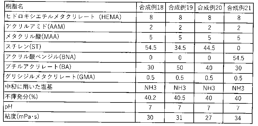
〔スラリー作製例1〕
人造黒鉛(初回充電容量390mAh/g、初回放電容量350mAh/g)96.0重量部、アセチレンブラック1.0重量部、を秤取り、自転・公転ミキサー(Thinky社製ARE-310)にて、自転1000rpm、公転2000rpmの条件で、30秒攪拌した。上記合成例1に示すバインダー組成物(HEA/AA=60/40,Na塩,重量平均分子量850000,不揮発分濃度14.8%)を蒸留水で希釈し、不揮発分濃度4.0%に調整した水溶液を、27.0重量部(固形分換算重量で1.08重量部)、蒸留水25.0重量部を加え、全体がペースト状になるまで混ぜ合わせた。次いで自転・公転ミキサー(Thinky社製ARE-310)にて、自転1000rpm、公転2000rpmの条件で、2分間攪拌し、攪拌により発熱したので氷水で室温まで冷却した。再度、自転1000rpm、公転2000rpmの条件で、2分間攪拌後、氷水で室温まで冷却した。先に不揮発分濃度4%に調製した上記合成例1に示すバインダー組成物の水溶液を、10.5重量部(不揮発分換算重量0.42重量部)を加え、全体が均一になるまで混ぜ合わせたのち、自転・公転ミキサー(Thinky社製ARE-310)にて、自転1000rpm、公転2000rpmの条件で、2分間攪拌し、氷水で室温に冷却した。蒸留水を7重量部と、スチレンブタジエン共重合体(SBR)(DIC社製 DS407H, 不揮発分濃度50.8%)を2.95重量部加え、再び自転・公転ミキサー(Thinky社製ARE-310)にて、自転1000rpm、公転2000rpmの条件で、30秒間攪拌することで負極合剤スラリーを調製した。
SBRの代わりに、合成例18で合成した水系ラテックス樹脂(Y)(ST/BA/HEMA/MMA/AAM/GMA=54.5/30/8/5/2/0.5、不揮発分濃度40.2%)を3.73重量部、用いた以外は、全てスラリー作製例1と同様にして負極合剤スラリーを作製した。
合成例1の代わりに、合成例4で合成したバインダー組成物(HBA/AA=60/40,Na塩,重量平均分子量800000,不揮発分濃度15.1%)、SBRの代わりに、合成例18で合成した水系ラテックス樹脂(Y)(ST/BA/HEMA/MMA/AAM/GMA=54.5/30/8/5/2/0.5、不揮発分濃度40.2%)を3.73重量部、を用いた以外は、全てスラリー作製例1と同様にして負極合剤スラリーを作製した。
合成例1の代わりに、合成例5で合成したバインダー組成物(HBA/CEA=60/40,Na塩,重量平均分子量840000,不揮発分濃度14.9%)、SBRの代わりに、合成例18で合成した水系ラテックス樹脂(Y)(ST/BA/HEMA/MMA/AAM/GMA=54.5/30/8/5/2/0.5、不揮発分濃度40.2%)を3.73重量部、を用いた以外は、全てスラリー作製例1と同様にして負極合剤スラリーを作製した。
合成例1の代わりに、合成例7で合成したバインダー組成物(HEA/AA/AAM=60/30/10,Na塩,重量平均分子量730000,不揮発分濃度15.1%)、SBRの代わりに、合成例18で合成した水系ラテックス樹脂(Y)(ST/BA/HEMA/MMA/AAM/GMA=54.5/30/8/5/2/0.5、不揮発分濃度40.2%)を3.73重量部、を用いた以外は、全てスラリー作製例1と同様にして負極合剤スラリーを作製した。
合成例1の代わりに、合成例8で合成したバインダー組成物(HEA/AA/AAM=20/20/60,アンモニウム塩,重量平均分子量780000,不揮発分濃度15.0%)、SBRの代わりに、合成例18で合成した水系ラテックス樹脂(Y)(ST/BA/HEMA/MMA/AAM/GMA=54.5/30/8/5/2/0.5、不揮発分濃度40.2%)を3.73重量部、を用いた以外は、全てスラリー作製例1と同様にして負極合剤スラリーを作製した。
合成例1の代わりに、合成例11で合成したバインダー組成物(HEA/AA/HAAM=20/20/60,アンモニウム塩,重量平均分子量830000,不揮発分濃度15.0%)、SBRの代わりに、合成例18で合成した水系ラテックス樹脂(Y)(ST/BA/HEMA/MMA/AAM/GMA=54.5/30/8/5/2/0.5、不揮発分濃度40.2%)を3.73重量部、を用いた以外は、全てスラリー作製例1と同様にして負極合剤スラリーを作製した。
合成例1の代わりに、合成例12で合成したバインダー組成物(HEA/AA/AAM=10/10/80,アンモニウム塩,重量平均分子量860000,不揮発分濃度14.9%)、SBRの代わりに、合成例18で合成した水系ラテックス樹脂(Y)(ST/BA/HEMA/MMA/AAM/GMA=54.5/30/8/5/2/0.5、不揮発分濃度40.2%)を3.73重量部、を用いた以外は、全てスラリー作製例1と同様にして負極合剤スラリーを作製した。
合成例1の代わりに、合成例13で合成したバインダー組成物(HEA/AA/AAM=35/35/30,アンモニウム塩,重量平均分子量840000,不揮発分濃度15.0%)、SBRの代わりに、合成例18で合成した水系ラテックス樹脂(Y)(ST/BA/HEMA/MMA/AAM/GMA=54.5/30/8/5/2/0.5、不揮発分濃度40.2%)を3.73重量部、を用いた以外は、全てスラリー作製例1と同様にして負極合剤スラリーを作製した。
合成例1の代わりに、合成例14で合成したバインダー組成物(HEA/AA/AAM=20/40/40,アンモニウム塩,重量平均分子量830000,不揮発分濃度15.1%)、SBRの代わりに、合成例18で合成した水系ラテックス樹脂(Y)(ST/BA/HEMA/MMA/AAM/GMA=54.5/30/8/5/2/0.5、不揮発分濃度40.2%)を3.73重量部、を用いた以外は、全てスラリー作製例1と同様にして負極合剤スラリーを作製した。
合成例1の代わりに、合成例15で合成したバインダー組成物(HEA/AA/AAM=30/20/50,アンモニウム塩,重量平均分子量840000,不揮発分濃度15.1%)、SBRの代わりに、合成例18で合成した水系ラテックス樹脂(Y)(ST/BA/HEMA/MMA/AAM/GMA=54.5/30/8/5/2/0.5、不揮発分濃度40.2%)を3.73重量部、を用いた以外は、全てスラリー作製例1と同様にして負極合剤スラリーを作製した。
合成例1の代わりに、合成例8で合成したバインダー組成物(HEA/AA/AAM=20/20/60,アンモニウム塩,重量平均分子量780000,不揮発分濃度15.0%)、SBRの代わりに、合成例19で合成した水系ラテックス樹脂(Y)(ST/BA/HEMA/MMA/AAM/GMA=54.5/30/8/5/2/0.5、不揮発分濃度40.2%)を3.73重量部、用いた以外は、全てスラリー作製例1と同様にして負極合剤スラリーを作製した。
合成例1の代わりに、合成例8で合成したバインダー組成物(HEA/AA/AAM=20/20/60,アンモニウム塩,重量平均分子量780000,不揮発分濃度15.0%)、SBRの代わりに、合成例19で合成した水系ラテックス樹脂(Y)(ST/BA/HEMA/MMA/AAM/GMA=34.5/50/8/5/2/0.5、不揮発分濃度40.5%)を3.70重量部、用いた以外は、全てスラリー作製例1と同様にして負極合剤スラリーを作製した。
合成例1の代わりに、合成例8で合成したバインダー組成物(HEA/AA/AAM=20/20/60,アンモニウム塩,重量平均分子量780000,不揮発分濃度15.0%)、SBRの代わりに、合成例20で合成した水系ラテックス樹脂(Y)(BNA/BA/HEMA/MMA/AAM/GMA=34.5/50/8/5/2/0.5、不揮発分濃度40.0%)を3.75重量部、用いた以外は、全てスラリー作製例1と同様にして負極合剤スラリーを作製した。
合成例1の代わりに、合成例9で合成したバインダー組成物(HEA/AA/AAM=20/20/60,Li塩,重量平均分子量780000,不揮発分濃度15.0%)、SBRの代わりに、合成例18で合成した水系ラテックス樹脂(Y)(ST/BA/HEMA/MMA/AAM/GMA=54.5/30/8/5/2/0.5、不揮発分濃度40.2%)を3.73重量部、を用いた以外は、全てスラリー作製例1と同様にして負極合剤スラリーを作製した。
合成例1の代わりに、合成例10で合成したバインダー組成物(HEA/AA/AAM=20/20/60,Na塩,重量平均分子量780000,不揮発分濃度15.0%)、SBRの代わりに、合成例18で合成した水系ラテックス樹脂(Y)(ST/BA/HEMA/MMA/AAM/GMA=54.5/30/8/5/2/0.5、不揮発分濃度40.2%)を3.73重量部、を用いた以外は、全てスラリー作製例1と同様にして負極合剤スラリーを作製した。
人造黒鉛(初回充電容量390mAh/g、初回放電容量350mAh/g)95.0重量部、アセチレンブラック1.0重量部、を秤取り、自転・公転ミキサー(Thinky社製ARE-310)にて、自転1000rpm、公転2000rpmの条件で、30秒攪拌した。上記合成例8で合成したバインダー組成物(HEA/AA/AAM=20/20/60,アンモニウム塩,重量平均分子量780000,不揮発分濃度15.0%)を蒸留水で希釈し、不揮発分濃度4.0%に調整した水溶液を、39.5重量部(固形分換算重量で1.58重量部)、蒸留水12.5重量部を加え、全体がペースト状になるまで混ぜ合わせた。次いで自転・公転ミキサー(Thinky社製ARE-310)にて、自転1000rpm、公転2000rpmの条件で、2分間攪拌し、攪拌により発熱したので氷水で室温まで冷却した。再度、自転1000rpm、公転2000rpmの条件で、2分間攪拌後、氷水で室温まで冷却した。先に不揮発分濃度4%に調製した上記合成例8に示すバインダー組成物の水溶液を、10.5重量部(不揮発分換算重量0.42重量部)を加え、全体が均一になるまで混ぜ合わせたのち、自転・公転ミキサー(Thinky社製ARE-310)にて、自転1000rpm、公転2000rpmの条件で、2分間攪拌し、氷水で室温に冷却した。蒸留水を6重量部と、合成例18で合成した水系ラテックス樹脂(Y)(ST/BA/HEMA/MMA/AAM/GMA=54.5/30/8/5/2/0.5、不揮発分濃度40.2%)を4.98重量部加え、再び自転・公転ミキサー(Thinky社製ARE-310)にて、自転1000rpm、公転2000rpmの条件で、30秒間攪拌することで負極合剤スラリーを調製した。
人造黒鉛(初回充電容量390mAh/g、初回放電容量350mAh/g)96.0重量部、アセチレンブラック1.0重量部、を秤取り、自転・公転ミキサー(Thinky社製ARE-310)にて、自転1000rpm、公転2000rpmの条件で、30秒攪拌した。上記合成例8で合成したバインダー組成物(HEA/AA/AAM=20/20/60,アンモニウム塩,重量平均分子量780000,不揮発分濃度15.0%)を蒸留水で希釈し、不揮発分濃度4.0%に調整した水溶液を、19.5重量部(固形分換算重量で0.78重量部)、蒸留水32.5重量部を加え、全体がペースト状になるまで混ぜ合わせた。次いで自転・公転ミキサー(Thinky社製ARE-310)にて、自転1000rpm、公転2000rpmの条件で、2分間攪拌し、攪拌により発熱したので氷水で室温まで冷却した。再度、自転1000rpm、公転2000rpmの条件で、2分間攪拌後、氷水で室温まで冷却した。先に不揮発分濃度4%に調製した上記合成例8に示すバインダー組成物の水溶液を、10.5重量部(不揮発分換算重量0.42重量部)を加え、全体が均一になるまで混ぜ合わせたのち、自転・公転ミキサー(Thinky社製ARE-310)にて、自転1000rpm、公転2000rpmの条件で、2分間攪拌し、氷水で室温に冷却した。蒸留水を6重量部と、合成例18で合成した水系ラテックス樹脂(Y)(ST/BA/HEMA/MMA/AAM/GMA=54.5/30/8/5/2/0.5、不揮発分濃度40.2%)を2.99重量部加え、再び自転・公転ミキサー(Thinky社製ARE-310)にて、自転1000rpm、公転2000rpmの条件で、30秒間攪拌することで負極合剤スラリーを調製した。
SiO負極材(初回充電容量2062mAh/g、初回放電容量1631mAh/g)3.7重量部、人造黒鉛(初回充電容量390mAh/g、初回放電容量350mAh/g)92.3重量部、アセチレンブラック1.0重量部、を秤取り、自転・公転ミキサー(Thinky社製ARE-310)にて、自転1000rpm、公転2000rpmの条件で、30秒攪拌した。上記合成例8で合成したバインダー組成物(HEA/AA/AAM=20/20/60,アンモニウム塩,重量平均分子量780000,不揮発分濃度15.0%)を蒸留水に溶解し、不揮発分濃度4.0%に調整した水溶液を、27.0重量部(固形分換算重量で1.08重量部)、蒸留水21.0重量部を加え、全体がペースト状になるまで混ぜ合わせた。次いで自転・公転ミキサー(Thinky社製ARE-310)にて、自転1000rpm、公転2000rpmの条件で、2分間攪拌し、攪拌により発熱したので氷水で室温まで冷却した。再度、自転1000rpm、公転2000rpmの条件で、2分間攪拌後、氷水で室温まで冷却した。先に不揮発分濃度4%に調製した上記合成例8で合成したバインダー組成物の水溶液を、10.5重量部(不揮発分換算重量0.42重量部)を加え、全体が均一になるまで混ぜ合わせたのち、自転・公転ミキサー(Thinky社製ARE-310)にて、自転1000rpm、公転2000rpmの条件で、2分間攪拌し、氷水で室温に冷却した。蒸留水を7重量部と、合成例18で合成した水系ラテックス樹脂(Y)(ST/BA/HEMA/MMA/AAM/GMA=54.5/30/8/5/2/0.5、不揮発分濃度40.2%)を3.73重量部加え、再び自転・公転ミキサー(Thinky社製ARE-310)にて、自転1000rpm、公転2000rpmの条件で、30秒間攪拌することで負極合剤スラリーを調製した。
SiO負極材(初回充電容量2062mAh/g、初回放電容量1631mAh/g)5.3重量部、人造黒鉛(初回充電容量390mAh/g、初回放電容量350mAh/g)90.7重量部を用いた以外は全てスラリー作製例19と同様にして負極合剤スラリーを作製した。
人造黒鉛(初回充電容量390mAh/g、初回放電容量350mAh/g)96.0重量部、アセチレンブラック1.0重量部、を秤取り、自転・公転ミキサー(Thinky社製ARE-310)にて、自転1000rpm、公転2000rpmの条件で、30秒攪拌した。カルボキシメチルセルロースNa塩(CMC、日本製紙社製サンローズMAC350HC)を蒸留水に溶解し、不揮発分濃度2.0%に調整した水溶液を、48.0重量部(固形分換算重量で0.96重量部)を加え、全体がペースト状になるまで混ぜ合わせた。次いで自転・公転ミキサー(Thinky社製ARE-310)にて、自転1000rpm、公転2000rpmの条件で、2分間攪拌し、攪拌により発熱したので氷水で室温まで冷却した。再度、自転1000rpm、公転2000rpmの条件で、2分間攪拌後、氷水で室温まで冷却した。先に不揮発分濃度2%に調製した上記CMCの水溶液を、27.0重量部(不揮発分換算重量0.54重量部)を加え、全体が均一になるまで混ぜ合わせたのち、自転・公転ミキサー(Thinky社製ARE-310)にて、自転1000rpm、公転2000rpmの条件で、2分間攪拌し、氷水で室温に冷却した。蒸留水を20重量部と、スチレンブタジエン共重合体(SBR)(DIC社製 DS407H, 不揮発分濃度50.8%)を2.95重量部加え、再び自転・公転ミキサー(Thinky社製ARE-310)にて、自転1000rpm、公転2000rpmの条件で、30秒間攪拌することで負極合剤スラリーを調製した。
人造黒鉛(初回充電容量390mAh/g、初回放電容量350mAh/g)96.0重量部、アセチレンブラック1.0重量部、を秤取り、自転・公転ミキサー(Thinky社製ARE-310)にて、自転1000rpm、公転2000rpmの条件で、30秒攪拌した。上記合成例1で合成したバインダー組成物(HEA/AA=60/40,Na塩,重量平均分子量850000,不揮発分濃度14.8%)、を蒸留水で希釈し、不揮発分濃度8.0%に調整した水溶液を、27.0重量部(固形分換算重量で2.16重量部)、蒸留水21.0重量部を加え、全体がペースト状になるまで混ぜ合わせた。次いで自転・公転ミキサー(Thinky社製ARE-310)にて、自転1000rpm、公転2000rpmの条件で、2分間攪拌し、攪拌により発熱したので氷水で室温まで冷却した。再度、自転1000rpm、公転2000rpmの条件で、2分間攪拌後、氷水で室温まで冷却した。先に不揮発分濃度8.0%に調製した上記合成例7で合成したバインダー組成物の水溶液を、10.5重量部(不揮発分換算重量0.84重量部)を加え、全体が均一になるまで混ぜ合わせたのち、自転・公転ミキサー(Thinky社製ARE-310)にて、自転1000rpm、公転2000rpmの条件で、2分間攪拌し、氷水で室温に冷却した。蒸留水を7重量部加え、再び自転・公転ミキサー(Thinky社製ARE-310)にて、自転1000rpm、公転2000rpmの条件で、30秒間攪拌することで負極合剤スラリーを調製した。
SBRの代わりに、合成例18で合成した水系ラテックス樹脂(Y)(ST/BA/HEMA/MMA/AAM/GMA=54.5/30/8/5/2/0.5、不揮発分濃度40.2%)を3.73重量部、を用いた以外は、全てスラリー作製例21と同様にして負極合剤スラリーを作製した。
合成例1の代わりに、合成例2で合成したバインダー組成物(HBA/AA=60/40,Na塩,重量平均分子量480000,不揮発分濃度15.0%)、SBRの代わりに、合成例18で合成した水系ラテックス樹脂(Y)(ST/BA/HEMA/MMA/AAM/GMA=54.5/30/8/5/2/0.5、不揮発分濃度40.2%)を3.73重量部、を用いた以外は、全てスラリー作製例1と同様にして負極合剤スラリーを作製した。
合成例1の代わりに、合成例3で合成したバインダー組成物(HBA/AA=75/35,Na塩,重量平均分子量750000,不揮発分濃度14.9%)、SBRの代わりに、合成例18で合成した水系ラテックス樹脂(Y)(ST/BA/HEMA/MMA/AAM/GMA=54.5/30/8/5/2/0.5、不揮発分濃度40.2%)を3.73重量部、を用いた以外は、全てスラリー作製例1と同様にして負極合剤スラリーを作製した。
合成例1の代わりに、合成例6で合成したバインダー組成物(HBA/AA=60/40,中和なし,重量平均分子量830000,不揮発分濃度15.0%)、SBRの代わりに、合成例18で合成した水系ラテックス樹脂(Y)(ST/BA/HEMA/MMA/AAM/GMA=54.5/30/8/5/2/0.5、不揮発分濃度40.2%)を3.73重量部、を用いた以外は、全てスラリー作製例1と同様にして負極合剤スラリーを作製した。
合成例1の代わりに、合成例16で合成したバインダー組成物(HEA/AAM=70/30,Na塩,重量平均分子量750000,不揮発分濃度15.0%)、SBRの代わりに、合成例18で合成した水系ラテックス樹脂(Y)(ST/BA/HEMA/MMA/AAM/GMA=54.5/30/8/5/2/0.5、不揮発分濃度40.2%)を3.73重量部、を用いた以外は、全てスラリー作製例1と同様にして負極合剤スラリーを作製した。
合成例1の代わりに、合成例17で合成したバインダー組成物(AA/AAM=70/30,Na塩,重量平均分子量820000,不揮発分濃度15.0%)、SBRの代わりに、合成例18で合成した水系ラテックス樹脂(Y)(ST/BA/HEMA/MMA/AAM/GMA=54.5/30/8/5/2/0.5、不揮発分濃度40.2%)を3.73重量部、を用いた以外は、全てスラリー作製例1と同様にして負極合剤スラリーを作製した。
合成例1の代わりに、ポリアクリル酸Na塩(和光純薬社製、重合度22000~70000)、SBRの代わりに、合成例18で合成した水系ラテックス樹脂(Y)(ST/BA/HEMA/MMA/AAM/GMA=54.5/30/8/5/2/0.5、不揮発分濃度40.2%)を3.73重量部、を用いた以外は、全てスラリー作製例1と同様にして負極合剤スラリーを作製した。
人造黒鉛(初回充電容量390mAh/g、初回放電容量350mAh/g)95.0重量部、アセチレンブラック1.0重量部、カルボキシメチルセルロースNa塩(CMC、日本製紙社製サンローズMAC350HC)2.0重量部を秤取り、自転・公転ミキサー(Thinky社製ARE-310)にて、自転1000rpm、公転2000rpmの条件で、30秒攪拌した。蒸留水48.0重量部を加え、全体がペースト状になるまで混ぜ合わせた。次いで自転・公転ミキサー(Thinky社製ARE-310)にて、自転1000rpm、公転2000rpmの条件で、2分間攪拌し、攪拌により発熱したので氷水で室温まで冷却した。再度、自転1000rpm、公転2000rpmの条件で、2分間攪拌後、氷水で室温まで冷却した。蒸留水10.5重量部を加え、全体が均一になるまで混ぜ合わせたのち、自転・公転ミキサー(Thinky社製ARE-310)にて、自転1000rpm、公転2000rpmの条件で、2分間攪拌し、氷水で室温に冷却した。蒸留水を25重量部と、スチレンブタジエン共重合体(SBR)(DIC社製 DS407H, 不揮発分濃度50.8%)を3.94重量部加え、再び自転・公転ミキサー(Thinky社製ARE-310)にて、自転1000rpm、公転2000rpmの条件で、30秒間攪拌することで負極合剤スラリーを調製した。
人造黒鉛(初回充電容量390mAh/g、初回放電容量350mAh/g)96.6重量部、アセチレンブラック1.0重量部、カルボキシメチルセルロースNa塩(CMC、日本製紙社製サンローズMAC350HC)1.2重量部を秤取り、自転・公転ミキサー(Thinky社製ARE-310)にて、自転1000rpm、公転2000rpmの条件で、30秒攪拌した。蒸留水48.0重量部を加え、全体がペースト状になるまで混ぜ合わせた。次いで自転・公転ミキサー(Thinky社製ARE-310)にて、自転1000rpm、公転2000rpmの条件で、2分間攪拌し、攪拌により発熱したので氷水で室温まで冷却した。再度、自転1000rpm、公転2000rpmの条件で、2分間攪拌後、氷水で室温まで冷却した。蒸留水10.5重量部(不揮発分換算重量0.42重量部)を加え、全体が均一になるまで混ぜ合わせたのち、自転・公転ミキサー(Thinky社製ARE-310)にて、自転1000rpm、公転2000rpmの条件で、2分間攪拌し、氷水で室温に冷却した。蒸留水を20重量部と、スチレンブタジエン共重合体(SBR)(DIC社製 DS407H, 不揮発分濃度50.8%)を2.36重量部加え、再び自転・公転ミキサー(Thinky社製ARE-310)にて、自転1000rpm、公転2000rpmの条件で、30秒間攪拌することで負極合剤スラリーを調製した。
SiO負極材(初回充電容量2062mAh/g、初回放電容量1631mAh/g)3.7重量部、人造黒鉛(初回充電容量390mAh/g、初回放電容量350mAh/g)92.3重量部、アセチレンブラック1.0重量部、を秤取り、自転・公転ミキサー(Thinky社製ARE-310)にて、自転1000rpm、公転2000rpmの条件で、30秒攪拌した。カルボキシメチルセルロースNa塩(CMC、日本製紙社製サンローズMAC350HC)を蒸留水に溶解し、不揮発分濃度2.0%に調整した水溶液を、48.0重量部(固形分換算重量で0.96重量部)を加え、全体がペースト状になるまで混ぜ合わせた。次いで自転・公転ミキサー(Thinky社製ARE-310)にて、自転1000rpm、公転2000rpmの条件で、2分間攪拌し、攪拌により発熱したので氷水で室温まで冷却した。再度、自転1000rpm、公転2000rpmの条件で、2分間攪拌後、氷水で室温まで冷却した。先に不揮発分濃度2%に調製した上記CMCの水溶液を、27.0重量部(不揮発分換算重量0.54重量部)を加え、全体が均一になるまで混ぜ合わせたのち、自転・公転ミキサー(Thinky社製ARE-310)にて、自転1000rpm、公転2000rpmの条件で、2分間攪拌し、氷水で室温に冷却した。蒸留水を20重量部と、スチレンブタジエン共重合体(SBR)(DIC社製 DS407H, 不揮発分濃度50.8%)を2.95重量部加え、再び自転・公転ミキサー(Thinky社製ARE-310)にて、自転1000rpm、公転2000rpmの条件で、30秒間攪拌することで負極合剤スラリーを調製した。
SiO負極材(初回充電容量2062mAh/g、初回放電容量1631mAh/g)5.3重量部、人造黒鉛(初回充電容量390mAh/g、初回放電容量350mAh/g)91.3重量部を用いた以外は全てスラリー作製例32と同様にして負極合剤スラリーを作製した。
〔実施例1〕
乾燥後の負極合剤塗工量(面密度)が13.2mg/cm2になるようにバーコータのギャップを調整し、このバーコータによりスラリー作製例1で調製した負極合剤スラリーを集電体である電解銅箔(厚さ10μm、幅180mm)上に塗工した。その後、80℃に設定した送風型乾燥機で8分乾燥した。乾燥した電極を幅40mmの短冊に切断し、ロールプレス機(テスター産業株式会社製 小型卓上ロールプレス SA-602)を用いて、合剤層密度が1.70g/cm3(合剤層の厚みで77.6μm)となるようにプレスした。110℃で10時間、真空乾燥したのち、合剤層密度を再度測定したところ、1.65g/cm3(合剤層の厚みで80.0μm)であった。この電極の単位面積当たりの初回充電容量は4.97mAh/cm2である。これにより、実施例1の負極(面密度13.2gm/cm2、合剤層密度1.65g/cm3、合剤層厚み80.0μm、単位面積初回充電容量4.97mAh/cm2)が得られた。
上記で作製した負極を温度25℃、相対湿度50%の恒温恒湿室内に6時間放置後、幅25mm、長さ100mmの短冊状に切り出した。ついで、両面テープ(日東電工社製 Nо5015)を用いてステンレス板に活物質面を被着面として張り合わせ、ピール強度試験用サンプルとした。銅箔端部を10mmほど引き剥がし、そこへポリイミドテープを貼り付け、剥離試験器への取り付け部とした。剥離試験機((株)島津製作所社製 オートグラフ AG-X Plus)にピール強度試験用サンプルを装着し、180度ピール試験を行った。ピール強度は34.5N/mであった。そして、負極塗膜の剥離(破壊)状態を観察した。また、負極塗膜をφ5mmの芯に巻き付け、塗膜にクラックが発生するか否かを目視観察した。このときのクラックの発生は無かった。
上記スラリー作製例2に示す負極合剤スラリーを用いた以外は、全て実施例1と同様にして実施例2の負極(面密度13.2gm/cm2、合剤層密度1.65g/cm3、合剤層厚み80.0μm、単位面積初回充電容量4.97mAh/cm2)を作製した。ロールプレスの圧力は、真空乾燥後の合剤層密度が1.65g/cm3(合剤層の厚みで80.0μm)となるように適宜調整した。このときのピール強度は31.5N/mであった。また、φ5mmの芯に巻き付けた時、クラックの発生は無かった。
上記スラリー作製例3に示す負極合剤スラリーを用いた以外は、全て実施例1と同様にして実施例3の負極(面密度13.2gm/cm2、合剤層密度1.65g/cm3、合剤層厚み80.0μm、単位面積初回充電容量4.97mAh/cm2)を作製した。ロールプレスの圧力は、真空乾燥後の合剤層密度が1.65g/cm3(合剤層の厚みで80.0μm)となるように適宜調整した。このときのピール強度は27.8N/mであった。また、φ5mmの芯に巻き付けた時、クラックの発生は無かった。
上記スラリー作製例4に示す負極合剤スラリーを用いた以外は、全て実施例1と同様にして負極(面密度13.2gm/cm2、合剤層密度1.65g/cm3、合剤層厚み80.0μm、単位面積初回充電容量4.97mAh/cm2)を作製した。ロールプレスの圧力は、真空乾燥後の合剤層密度が1.65g/cm3(合剤層の厚みで80.0μm)となるように適宜調整した。このときのピール強度は28.9N/mであった。また、φ5mmの芯に巻き付けた時、クラックの発生は無かった。
上記スラリー作製例5に示す負極合剤スラリーを用いた以外は、全て実施例1と同様にして負極(面密度13.2gm/cm2、合剤層密度1.65g/cm3、合剤層厚み80.0μm、単位面積初回充電容量4.97mAh/cm2)を作製した。ロールプレスの圧力は、真空乾燥後の合剤層密度が1.65g/cm3(合剤層の厚みで80.0μm)となるように適宜調整した。このときのピール強度は28.9N/mであった。また、φ5mmの芯に巻き付けた時、クラックの発生は無かった。
上記スラリー作製例6に示す負極合剤スラリーを用いた以外は、全て実施例1と同様にして負極(面密度13.2gm/cm2、合剤層密度1.65g/cm3、合剤層厚み80.0μm、単位面積初回充電容量4.97mAh/cm2)を作製した。ロールプレスの圧力は、真空乾燥後の合剤層密度が1.65g/cm3(合剤層の厚みで80.0μm)となるように適宜調整した。このときのピール強度は30.7N/mであった。また、φ5mmの芯に巻き付けた時、クラックの発生は無かった。
上記スラリー作製例7に示す負極合剤スラリーを用いた以外は、全て実施例1と同様にして負極(面密度13.2gm/cm2、合剤層密度1.65g/cm3、合剤層厚み80.0μm、単位面積初回充電容量4.97mAh/cm2)を作製した。ロールプレスの圧力は、真空乾燥後の合剤層密度が1.65g/cm3(合剤層の厚みで80.0μm)となるように適宜調整した。このときのピール強度は28.4N/mであった。また、φ5mmの芯に巻き付けた時、クラックの発生は無かった。
上記スラリー作製例8に示す負極合剤スラリーを用いた以外は、全て実施例1と同様にして負極(面密度13.2gm/cm2、合剤層密度1.65g/cm3、合剤層厚み80.0μm、単位面積初回充電容量4.97mAh/cm2)を作製した。ロールプレスの圧力は、真空乾燥後の合剤層密度が1.65g/cm3(合剤層の厚みで80.0μm)となるように適宜調整した。このときのピール強度は29.1N/mであった。また、φ5mmの芯に巻き付けた時、クラックの発生は無かった。
上記スラリー作製例9に示す負極合剤スラリーを用いた以外は、全て実施例1と同様にして負極(面密度13.2gm/cm2、合剤層密度1.65g/cm3、合剤層厚み80.0μm、単位面積初回充電容量4.97mAh/cm2)を作製した。ロールプレスの圧力は、真空乾燥後の合剤層密度が1.65g/cm3(合剤層の厚みで80.0μm)となるように適宜調整した。このときのピール強度は30.5N/mであった。また、φ5mmの芯に巻き付けた時、クラックの発生は無かった。
上記スラリー作製例10に示す負極合剤スラリーを用いた以外は、全て実施例1と同様にして負極(面密度13.2gm/cm2、合剤層密度1.65g/cm3、合剤層厚み80.0μm、単位面積初回充電容量4.97mAh/cm2)を作製した。ロールプレスの圧力は、真空乾燥後の合剤層密度が1.65g/cm3(合剤層の厚みで80.0μm)となるように適宜調整した。このときのピール強度は28.6N/mであった。また、φ5mmの芯に巻き付けた時、クラックの発生は無かった。
上記スラリー作製例11に示す負極合剤スラリーを用いた以外は、全て実施例1と同様にして負極(面密度13.2gm/cm2、合剤層密度1.65g/cm3、合剤層厚み80.0μm、単位面積初回充電容量4.97mAh/cm2)を作製した。ロールプレスの圧力は、真空乾燥後の合剤層密度が1.65g/cm3(合剤層の厚みで80.0μm)となるように適宜調整した。このときのピール強度は28.6N/mであった。また、φ5mmの芯に巻き付けた時、クラックの発生は無かった。
上記スラリー作製例12に示す負極合剤スラリーを用いた以外は、全て実施例1と同様にして負極(面密度13.2gm/cm2、合剤層密度1.65g/cm3、合剤層厚み80.0μm、単位面積初回充電容量4.97mAh/cm2)を作製した。ロールプレスの圧力は、真空乾燥後の合剤層密度が1.65g/cm3(合剤層の厚みで80.0μm)となるように適宜調整した。このときのピール強度は30.1N/mであった。また、φ5mmの芯に巻き付けた時、クラックの発生は無かった。
上記スラリー作製例13に示す負極合剤スラリーを用いた以外は、全て実施例1と同様にして負極(面密度13.2gm/cm2、合剤層密度1.65g/cm3、合剤層厚み80.0μm、単位面積初回充電容量4.97mAh/cm2)を作製した。ロールプレスの圧力は、真空乾燥後の合剤層密度が1.65g/cm3(合剤層の厚みで80.0μm)となるように適宜調整した。このときのピール強度は32N/mであった。また、φ5mmの芯に巻き付けた時、クラックの発生は無かった。
上記スラリー作製例14に示す負極合剤スラリーを用いた以外は、全て実施例1と同様にして負極(面密度13.2gm/cm2、合剤層密度1.65g/cm3、合剤層厚み80.0μm、単位面積初回充電容量4.97mAh/cm2)を作製した。ロールプレスの圧力は、真空乾燥後の合剤層密度が1.65g/cm3(合剤層の厚みで80.0μm)となるように適宜調整した。このときのピール強度は29.8N/mであった。また、φ5mmの芯に巻き付けた時、クラックの発生は無かった。
上記スラリー作製例15に示す負極合剤スラリーを用いた以外は、全て実施例1と同様にして負極(面密度13.2gm/cm2、合剤層密度1.65g/cm3、合剤層厚み80.0μm、単位面積初回充電容量4.97mAh/cm2)を作製した。ロールプレスの圧力は、真空乾燥後の合剤層密度が1.65g/cm3(合剤層の厚みで80.0μm)となるように適宜調整した。このときのピール強度は29.5N/mであった。また、φ5mmの芯に巻き付けた時、クラックの発生は無かった。
上記スラリー作製例16に示す負極合剤スラリーを用いた以外は、全て実施例1と同様にして負極(面密度13.2gm/cm2、合剤層密度1.65g/cm3、合剤層厚み80.0μm、単位面積初回充電容量4.97mAh/cm2)を作製した。ロールプレスの圧力は、真空乾燥後の合剤層密度が1.65g/cm3(合剤層の厚みで80.0μm)となるように適宜調整した。このときのピール強度は34.6N/mであった。また、φ5mmの芯に巻き付けた時、クラックの発生は無かった。
上記スラリー作製例17に示す負極合剤スラリーを用いた以外は、全て実施例1と同様にして負極(面密度13.2gm/cm2、合剤層密度1.65g/cm3、合剤層厚み80.0μm、単位面積初回充電容量4.89mAh/cm2)を作製した。ロールプレスの圧力は、真空乾燥後の合剤層密度が1.65g/cm3(合剤層の厚みで80.0μm)となるように適宜調整した。このときのピール強度は56.0N/mであった。また、φ5mmの芯に巻き付けた時、クラックの発生は無かった。
上記スラリー作製例18に示す負極合剤スラリーを用いた以外は、全て実施例1と同様にして負極(面密度13.2gm/cm2、合剤層密度1.65g/cm3、合剤層厚み80.0μm、単位面積初回充電容量4.97mAh/cm2)を作製した。ロールプレスの圧力は、真空乾燥後の合剤層密度が1.65g/cm3(合剤層の厚みで80.0μm)となるように適宜調整した。このときのピール強度は16.2N/mであった。また、φ5mmの芯に巻き付けた時、クラックの発生は無かった。
上記スラリー作製例6に示す負極合剤スラリーを用い、真空乾燥後の電極密度の値が1.40g/cm3(合剤層の厚みで94.3μm)となるようにロールプレスの圧力を適宜調整した以外は、全て実施例1と同様にして負極(面密度13.2gm/cm2、合剤層密度1.40g/cm3、合剤層厚み94.3μm、単位面積初回充電容量4.97mAh/cm2)を作製した。このときのピール強度は29.0N/mであった。また、φ5mmの芯に巻き付けた時、クラックの発生は無かった。
上記スラリー作製例6に示す負極合剤スラリーを用い、真空乾燥後の電極密度の値が1.75g/cm3(合剤層の厚みで75.4μm)となるようにロールプレスの圧力を適宜調整した以外は、全て実施例1と同様にして負極(面密度13.2gm/cm2、合剤層密度1.75g/cm3、合剤層厚み75.4μm、単位面積初回充電容量4.97mAh/cm2)を作製した。このときのピール強度は35.2N/mであった。また、φ5mmの芯に巻き付けた時、クラックの発生は無かった。
上記スラリー作製例6に示す負極合剤スラリーを用い、負極合剤塗工量(面密度)が18.2mg/cm2になるようにバーコータのギャップを調整した以外は、全て実施例1と同様にして負極(面密度18.2gm/cm2、合剤層密度1.65g/cm3、合剤層厚み110.0μm、単位面積初回充電容量6.81mAh/cm2)を作製した。ロールプレスの圧力は、真空乾燥後の合剤層密度が1.65g/cm3(合剤層の厚みで110.3μm)となるように適宜調整した。このときのピール強度は30.1N/mであった。また、φ5mmの芯に巻き付けた時、クラックの発生は無かった。
上記スラリー作製例6に示す負極合剤スラリーを用い、負極合剤塗工量(面密度)が20.7mg/cm2になるようにバーコータのギャップを調整した以外は、全て実施例1と同様にして負極(面密度20.7gm/cm2、合剤層密度1.65g/cm3、合剤層厚み125.5μm、単位面積初回充電容量7.75mAh/cm2)を作製した。ロールプレスの圧力は、真空乾燥後の合剤層密度が1.65g/cm3(合剤層の厚みで125.5μm)となるように適宜調整した。このときのピール強度は25.5N/mであった。また、φ5mmの芯に巻き付けた時、クラックの発生は無かった。
上記スラリー作製例19に示す負極合剤スラリーを用い、負極合剤塗工量(面密度)が11.3mg/cm2になるようにバーコータのギャップを調整し、真空乾燥後の電極密度の値が1.65g/cm3(合剤層の厚みで68.5μm)となるようにロールプレスの圧力を適宜調整した以外は、全て実施例1と同様にして負極(面密度11.3gm/cm2、合剤層密度1.65g/cm3、合剤層厚み68.5μm、単位面積初回充電容量4.94mAh/cm2)を作製した。このときのピール強度は32.0N/mであった。また、φ5mmの芯に巻き付けた時、クラックの発生は無かった。
上記スラリー作製例20に示す負極合剤スラリーを用い、負極合剤塗工量(面密度)が10.7mg/cm2になるようにバーコータのギャップを調整し、真空乾燥後の電極密度の値が1.65g/cm3(合剤層の厚みで64.8μm)となるようにロールプレスの圧力を適宜調整した以外は、全て実施例1と同様にして負極(面密度10.7gm/cm2、合剤層密度1.65g/cm3、合剤層厚み64.8μm、単位面積初回充電容量4.98mAh/cm2)を作製した。このときのピール強度は34.0N/mであった。また、φ5mmの芯に巻き付けた時、クラックの発生は無かった。
上記スラリー作製例21に示す負極合剤スラリーを用いた以外は、全て実施例1と同様にして負極(面密度13.2gm/cm2、合剤層密度1.65g/cm3、合剤層厚み80.0μm、単位面積初回充電容量4.97mAh/cm2)を作製した。ロールプレスの圧力は、真空乾燥後の合剤層密度が1.65g/cm3(合剤層の厚みで80.0μm)となるように適宜調整した。このときのピール強度は16.8N/mであった。また、φ5mmの芯に巻き付けた時、クラックの発生は無かった。
上記スラリー作製例22に示す負極合剤スラリーを用いた以外は、全て実施例1と同様にして負極(面密度13.2gm/cm2、合剤層密度1.65g/cm3、合剤層厚み80.0μm、単位面積初回充電容量4.97mAh/cm2)を作製した。ロールプレスの圧力は、真空乾燥後の合剤層密度が1.65g/cm3(合剤層の厚みで80.0μm)となるように適宜調整した。このときのピール強度は38.0N/mであった。また、φ5mmの芯に巻き付けた時、クラックの発生は無かった。
上記スラリー作製例23に示す負極合剤スラリーを用いた以外は、全て実施例1と同様にして負極(面密度13.2gm/cm2、合剤層密度1.65g/cm3、合剤層厚み80.0μm、単位面積初回充電容量4.97mAh/cm2)を作製した。ロールプレスの圧力は、真空乾燥後の合剤層密度が1.65g/cm3(合剤層の厚みで80.0μm)となるように適宜調整した。このときのピール強度は14.8N/mであった。また、φ5mmの芯に巻き付けた時、クラックの発生は無かった。
上記スラリー作製例24に示す負極合剤スラリーを用いた以外は、全て実施例1と同様にして負極(面密度13.2gm/cm2、合剤層密度1.65g/cm3、合剤層厚み80.0μm、単位面積初回充電容量4.97mAh/cm2)を作製した。ロールプレスの圧力は、真空乾燥後の合剤層密度が1.65g/cm3(合剤層の厚みで80.0μm)となるように適宜調整した。このときのピール強度は17.4N/mであった。また、φ5mmの芯に巻き付けた時、クラックの発生は無かった。
上記スラリー作製例25に示す負極合剤スラリーを用いた以外は、全て実施例1と同様にして負極(面密度13.2gm/cm2、合剤層密度1.65g/cm3、合剤層厚み80.0μm、単位面積初回充電容量4.97mAh/cm2)を作製した。ロールプレスの圧力は、真空乾燥後の合剤層密度が1.65g/cm3(合剤層の厚みで80.0μm)となるように適宜調整した。このときのピール強度は14.5N/mであった。また、φ5mmの芯に巻き付けた時、クラックの発生は無かった。
上記スラリー作製例26に示す負極合剤スラリーを用いた以外は、全て実施例1と同様にして負極(面密度13.2gm/cm2、合剤層密度1.65g/cm3、合剤層厚み80.0μm、単位面積初回充電容量4.97mAh/cm2)を作製した。ロールプレスの圧力は、真空乾燥後の合剤層密度が1.65g/cm3(合剤層の厚みで80.0μm)となるように適宜調整した。このときのピール強度は18.0N/mであった。また、φ5mmの芯に巻き付けた時、クラックの発生は無かった。
上記スラリー作製例27(面密度13.2gm/cm2、合剤層密度1.65g/cm3、合剤層厚み80.0μm、単位面積初回充電容量4.97mAh/cm2)に示す負極合剤スラリーを用いた以外は、全て実施例1と同様にして負極を作製した。ロールプレスの圧力は、真空乾燥後の合剤層密度が1.65g/cm3(合剤層の厚みで80.0μm)となるように適宜調整した。このときのピール強度は15.2N/mであった。また、φ5mmの芯に巻き付けた時、クラックの発生は無かった。
上記スラリー作製例28に示す負極合剤スラリーを用いた以外は、全て実施例1と同様にして負極(面密度13.2gm/cm2、合剤層密度1.65g/cm3、合剤層厚み80.0μm、単位面積初回充電容量4.97mAh/cm2)を作製した。ロールプレスの圧力は、真空乾燥後の合剤層密度が1.65g/cm3(合剤層の厚みで80.0μm)となるように適宜調整した。このときのピール強度は14.5N/mであった。また、φ5mmの芯に巻き付けた時、クラックの発生は無かった。
上記スラリー作製例29に示す負極合剤スラリーを用いた以外は、全て実施例1と同様にして負極(面密度13.2gm/cm2、合剤層密度1.65g/cm3、合剤層厚み80.0μm、単位面積初回充電容量4.97mAh/cm2)を作製した。ロールプレスの圧力は、真空乾燥後の合剤層密度が1.65g/cm3(合剤層の厚みで80.0μm)となるように適宜調整した。このときのピール強度は16.4N/mであった。また、φ5mmの芯に巻き付けた時、クラックの発生は無かった。
上記スラリー作製例17に示す負極合剤スラリーを用いた以外は、全て実施例1と同様にして負極(面密度13.2gm/cm2、合剤層密度1.65g/cm3、合剤層厚み80.0μm、単位面積初回充電容量4.89mAh/cm2)を作製した。ロールプレスの圧力は、真空乾燥後の合剤層密度が1.65g/cm3(合剤層の厚みで80.0μm)となるように適宜調整した。このときのピール強度は56.0N/mであった。また、φ5mmの芯に巻き付けた時、クラックの発生は無かった。
上記スラリー作製例18に示す負極合剤スラリーを用いた以外は、全て実施例1と同様にして負極(面密度13.2gm/cm2、合剤層密度1.65g/cm3、合剤層厚み80.0μm、単位面積初回充電容量4.97mAh/cm2)を作製した。ロールプレスの圧力は、真空乾燥後の合剤層密度が1.65g/cm3(合剤層の厚みで80.0μm)となるように適宜調整した。このときのピール強度は16.2N/mであった。また、φ5mmの芯に巻き付けた時、クラックの発生は無かった。
上記スラリー作製例21に示す負極合剤スラリーを用い、真空乾燥後の電極密度の値が1.40g/cm3(合剤層の厚みで94.3μm)となるようにロールプレスの圧力を適宜調整した以外は、全て実施例1と同様にして負極(面密度13.2gm/cm2、合剤層密度1.40g/cm3、合剤層厚み94.3μm、単位面積初回充電容量4.97mAh/cm2)を作製した。ロールプレスの圧力は、真空乾燥後の合剤層密度が1.40g/cm3(合剤層の厚みで94.3μm)となるように適宜調整した。このときのピール強度は14.6N/mであった。また、φ5mmの芯に巻き付けた時、クラックの発生は無かった。
上記スラリー作製例21に示す負極合剤スラリーを用い、真空乾燥後の電極密度の値が1.75g/cm3(合剤層の厚みで75.4μm)となるようにロールプレスの圧力を適宜調整した以外は、全て実施例1と同様にして負極(面密度13.2gm/cm2、合剤層密度1.75g/cm3、合剤層厚み75.4μm、単位面積初回充電容量4.97mAh/cm2)を作製した。ロールプレスの圧力は、真空乾燥後の合剤層密度が1.75g/cm3(合剤層の厚みで75.4μm)となるように適宜調整した。このときのピール強度は18.2N/mであった。また、φ5mmの芯に巻き付けた時、クラックの発生は無かった。
上記スラリー作製例21に示す負極合剤スラリーを用い、負極合剤塗工量(面密度)が18.2mg/cm2になるようにバーコータのギャップを調整した以外は、全て実施例1と同様にして負極(面密度18.2gm/cm2、合剤層密度1.65g/cm3、合剤層厚み110.0μm、単位面積初回充電容量6.18mAh/cm2)を作製した。ロールプレスの圧力は、真空乾燥後の合剤層密度が1.65g/cm3(合剤層の厚みで110.0μm)となるように適宜調整した。このときのピール強度は20.0N/mであった。また、φ5mmの芯に巻き付けた時、クラックの発生は無かった。
上記スラリー作製例21に示す負極合剤スラリーを用い、負極合剤塗工量(面密度)が20.7mg/cm2になるようにバーコータのギャップを調整した以外は、全て実施例1と同様にして負極(面密度20.7gm/cm2、合剤層密度1.65g/cm3、合剤層厚み125.5μm、単位面積初回充電容量7.75mAh/cm2)を作製した。ロールプレスの圧力は、真空乾燥後の合剤層密度が1.65g/cm3(合剤層の厚みで125.5μm)となるように適宜調整した。このときのピール強度は13.2N/mであった。また、φ5mmの芯に巻き付けた時、クラックの発生は無かった。
上記スラリー作製例30に示す負極合剤スラリーを用い、負極合剤塗工量(面密度)が11.3mg/cm2になるようにバーコータのギャップを調整し、真空乾燥後の電極密度の値が1.65g/cm3(合剤層の厚みで68.5μm)となるようにロールプレスの圧力を適宜調整した以外は、全て実施例1と同様にして負極(面密度11.3gm/cm2、合剤層密度1.65g/cm3、合剤層厚み68.5μm、単位面積初回充電容量4.94mAh/cm2)を作製した。このときのピール強度は20.3N/mであった。また、φ5mmの芯に巻き付けた時、クラックの発生は無かった。
上記スラリー作製例31に示す負極合剤スラリーを用い、負極合剤塗工量(面密度)が10.7mg/cm2になるようにバーコータのギャップを調整し、真空乾燥後の電極密度の値が1.65g/cm3(合剤層の厚みで64.8μm)となるようにロールプレスの圧力を適宜調整した以外は、全て実施例1と同様にして負極(面密度10.7gm/cm2、合剤層密度1.65g/cm3、合剤層厚み64.8μm、単位面積初回充電容量4.98mAh/cm2)を作製した。このときのピール強度は22.5N/mであった。また、φ5mmの芯に巻き付けた時、クラックの発生は無かった。
「正極合剤スラリーの調製」
正極材LiMn0.6Co0.2Ni0.2O2 (初回充電容量191mAh/g、初回放電容量171mAh/g)94.0重量部、アセチレンブラック3.0重量部、ポリフッ化ビニリデン3.0重量部をN-メチル-2-ピロリドンに分散させることで、正極合剤スラリーを形成した。なお、正極合剤スラリー中の不揮発分はスラリー総質量に対して50重量部であった。
露点-30℃以下に制御したドライルーム内で、正極材LiMn0.6Co0.2Ni0.2O2(初回充電容量191mAh/g、初回放電容量171mAh/g)94.0重量部、アセチレンブラック3.0重量部を秤取り、自転・公転ミキサー(Thinky社製ARE-310)にて、自転1000rpm、公転2000rpmの条件で、30秒攪拌した。ポリフッ化ビニリデン(クレハ社製PVDF、#1100)の10%NMP溶液を30.0重量部(固形分換算重量で3.0重量部)加え、全体がペースト状になるまで混ぜ合わせた。次いで自転・公転ミキサー(Thinky社製ARE-310)にて、自転1000rpm、公転2000rpmの条件で1分間攪拌した。攪拌により発熱したので室温まで放冷した。この自転・公転ミキサーによる攪拌と、放冷の操作を更に3回繰り返した。次にNMP10.0重量部加え、全体が均一になるまで混ぜ合わせた。次いで自転・公転ミキサー(Thinky社製ARE-310)にて、自転1000rpm、公転2000rpmの条件で1分間攪拌した。攪拌により発熱したので室温まで放冷した。この自転・公転ミキサーによる攪拌と、放冷の操作を更に3回繰り返した。次にNMP10.0重量部加え、自転・公転ミキサー(Thinky社製ARE-310)にて、自転1000rpm、公転2000rpmの条件で、2分間攪拌することで正極合剤スラリーを調製した。
「面密度25.0mg/cm2の正極作製」
まず、乾燥後の合剤塗工量(面密度)が25.0mg/cm2になるようにバーコータのギャップを調整し、このバーコータにより上記で調製した正極合剤スラリーを集電体であるアルミニウム集電箔(厚さ15μm、幅180mm)上に塗工した。次に、正極合剤スラリーを80℃に設定した送風型乾燥機で15分乾燥した。そして、乾燥後の正極合剤をロールプレス機により合剤密度が3.40g/cm3となるようにプレスした。最後に、正極合剤を110℃で10時間真空乾燥することで、面密度25.0mg/cm2の正極(面密度25.0gm/cm2、合剤層密度3.40g/cm3、合剤層厚み73.5μm、単位面積初回充電容量4.49mAh/cm2)を作製した。
「面密度34.2mg/cm2の正極作製」
合剤塗工量(面密度)が34.2mg/cm2になるようにバーコータのギャップを調整した以外は全て正極作製例1と同様にして正極(面密度34.2gm/cm2、合剤層密度3.40g/cm3、合剤層厚み58.4μm、単位面積初回充電容量6.14mAh/cm2)
「面密度39.2mg/cm2の正極作製」
合剤塗工量(面密度)が39.2mg/cm2になるようにバーコータのギャップを調整した以外は全て正極作製例1と同様にして正極(面密度39.2gm/cm2、合剤層密度3.40g/cm3、合剤層厚み68.0μm、単位面積初回充電容量7.04mAh/cm2)
〔実施例25〕
実施例1で示した負極をTabの付いた24mm×24mmの正方形に、正極作製例1で示した正極をTabの付いた22mm×22mmの正方形に、トムソン刃を用いて各々カットした。カットした電極のTab部に負極はニッケル、正極はアルミのタブリードを各々溶接した。次に、セパレータ(厚み20ミクロンのポリエチレン製微多孔膜)を28mm×38mmの長方形にトムソン刃を用いてカットした。セパレータを介して正極と負極を対向させ、ラミネートフィルムで包装し、Tab部を熱圧着により固定した。そして、電解液(1.0MのLiPF6 エチレンカーボネート/ジメチルカーボネート/メチルエチルカーボネート=30/30/40混合溶液(体積比)+1%ビニルカーボネート+5%フルオロエチレンカーボネート)を300μL加え、真空ラミネートすることで封じ、ラミネート型二次電池を作製した。
上記で作製した二次電池を2枚のゴアハイパーシート、更にその上から2枚のアクリル板で挟み、ダブルクリップ2個で固定し、電極部位に一定の圧力が均一に掛かる状態で固定した。これを充放電装置に取り付け、25℃で3時間放置後、0.1Cの充放電レートで1回充放電した。このときの初回充放電効率は84.6%であった。
初回充放電後、45℃に保持し、0.5Cで1回充電を行ったのち、ドライルーム内で二次電池を解体し、満充電状態の負極を取り出した。ジメチルカーボネートで洗浄、自然乾燥後、マイクロメータにて電極厚みを測定し、集電体の厚みを減ずることで合剤層の厚みを得た。充電前の電極合剤層厚みを100として電極膨張率を算出した結果、17.5%であった。
初回充放電後の上記で作製した二次電池温度を45℃に保持し、0.5Cで100回充放電を繰り返した。0.5C1回目の放電容量を100%とした時の100サイクル後の放電容量維持率は91.8%であった。
初回充放電後の上記で作製した二次電池温度を-10℃に保持し、0.5Cで100回充放電を繰り返した。0.5C1回目の放電容量を100%とした時の50サイクル後の放電容量維持率は84.9%であった。
実施例2で示した負極を用いた以外は、全て実施例25と同時にして行った。得られた二次電池の初回充放電容量は85.0%、電極膨張率は16.3%、45℃0.5Cで100サイクル後の放電容量維持率は93.2%、-10℃0.5Cで50サイクル後の放電容量維持率は85.6%であった。
実施例3で示した負極を用いた以外は、全て実施例25と同時にして行った。得られた二次電池の初回充放電容量は84.9%、電極膨張率は16.6%、45℃0.5Cで100サイクル後の放電容量維持率は93.3%、-10℃0.5Cで50サイクル後の放電容量維持率は85.5%であった。
実施例4で示した負極を用いた以外は、全て実施例25と同時にして行った。得られた二次電池の初回充放電容量は84.8%、電極膨張率は16.5%、45℃0.5Cで100サイクル後の放電容量維持率は91.7%、-10℃0.5Cで50サイクル後の放電容量維持率は84.8%であった。
実施例5で示した負極を用いた以外は、全て実施例25と同時にして行った。得られた二次電池の初回充放電容量は85.0%、電極膨張率は17.0%、45℃0.5Cで100サイクル後の放電容量維持率は91.5%、-10℃0.5Cで50サイクル後の放電容量維持率は84.6%であった。
実施例6で示した負極を用いた以外は、全て実施例25と同時にして行った。得られた二次電池の初回充放電容量は85.0%、電極膨張率は16.8%、45℃0.5Cで100サイクル後の放電容量維持率は92.1%、-10℃0.5Cで50サイクル後の放電容量維持率は85.0%であった。
実施例7で示した負極を用いた以外は、全て実施例25と同時にして行った。得られた二次電池の初回充放電容量は84.9%、電極膨張率は16.4%、45℃0.5Cで100サイクル後の放電容量維持率は91.8%、-10℃0.5Cで50サイクル後の放電容量維持率は85.2%であった。
実施例8で示した負極を用いた以外は、全て実施例25と同時にして行った。得られた二次電池の初回充放電容量は84.8%、電極膨張率は16.7%、45℃0.5Cで100サイクル後の放電容量維持率は91.5%、-10℃0.5Cで50サイクル後の放電容量維持率は84.9%であった。
実施例9で示した負極を用いた以外は、全て実施例25と同時にして行った。得られた二次電池の初回充放電容量は84.8%、電極膨張率は16.4%、45℃0.5Cで100サイクル後の放電容量維持率は91.7%、-10℃0.5Cで50サイクル後の放電容量維持率は85.0%であった。
実施例10で示した負極を用いた以外は、全て実施例25と同時にして行った。得られた二次電池の初回充放電容量は84.9%、電極膨張率は16.3%、45℃0.5Cで100サイクル後の放電容量維持率は91.5%、-10℃0.5Cで50サイクル後の放電容量維持率は83.9%であった。
実施例11で示した負極を用いた以外は、全て実施例25と同時にして行った。得られた二次電池の初回充放電容量は84.8%、電極膨張率は16.5%、45℃0.5Cで100サイクル後の放電容量維持率は91.7%、-10℃0.5Cで50サイクル後の放電容量維持率は84.5%であった。
実施例12で示した負極を用いた以外は、全て実施例25と同時にして行った。得られた二次電池の初回充放電容量は84.9%、電極膨張率は16.6%、45℃0.5Cで100サイクル後の放電容量維持率は91.8%、-10℃0.5Cで50サイクル後の放電容量維持率は85.2%であった。
実施例13で示した負極を用いた以外は、全て実施例25と同時にして行った。得られた二次電池の初回充放電容量は84.9%、電極膨張率は16.3%、45℃0.5Cで100サイクル後の放電容量維持率は91.4%、-10℃0.5Cで50サイクル後の放電容量維持率は84.7%であった。
実施例14で示した負極を用いた以外は全て、実施例25と同時にして行った。得られた二次電池の初回充放電容量は84.9%、電極膨張率は16.4%、45℃0.5Cで50サイクル後の放電容量維持率は91.8%、-10℃0.5Cで50サイクル後の放電容量維持率は84.5%であった。
実施例15で示した負極を用いた以外は、全て実施例25と同時にして行った。得られた二次電池の初回充放電容量は86.2%、電極膨張率は16.7%、45℃0.5Cで100サイクル後の放電容量維持率は92.1%、-10℃0.5Cで50サイクル後の放電容量維持率は85.4%であった。
実施例16で示した負極を用いた以外は、全て実施例25と同時にして行った。得られた二次電池の初回充放電容量は85.1%、電極膨張率は16.5%、45℃0.5Cで100サイクル後の放電容量維持率は92.2%、-10℃0.5Cで50サイクル後の放電容量維持率は85.5%であった。
実施例17で示した負極を用いた以外は、全て実施例25と同時にして行った。得られた二次電池の初回充放電容量は84.9%、電極膨張率は16.9%、45℃0.5Cで50サイクル後の放電容量維持率は91.0%、-10℃0.5Cで50サイクル後の放電容量維持率は84.4%であった。
実施例18で示した負極を用いた以外は、全て実施例25と同時にして行った。得られた二次電池の初回充放電容量は84.2%、電極膨張率は18.2%、45℃0.5Cで100サイクル後の放電容量維持率は92.4%、-10℃0.5Cで50サイクル後の放電容量維持率は85.7%であった。
実施例19で示した負極を用いた以外は、全て実施例25と同時にして行った。得られた二次電池の初回充放電容量は84.9%、電極膨張率は16.8%、45℃0.5Cで100サイクル後の放電容量維持率は93.1%、-10℃0.5Cで50サイクル後の放電容量維持率は86.3%であった。
実施例20で示した負極を用いた以外は、全て実施例25と同時にして行った。得られた二次電池の初回充放電容量は84.8%、電極膨張率は17.2%、45℃0.5Cで100サイクル後の放電容量維持率は90.1%、-10℃0.5Cで50サイクル後の放電容量維持率は83.5%であった。
実施例21で示した負極と正極作製例2で示した正極を用いた以外は、全て実施例25と同時にして行った。得られた二次電池の初回充放電容量は84.0%、電極膨張率は19.6%、45℃0.5Cで100サイクル後の放電容量維持率は88.3%、-10℃0.5Cで50サイクル後の放電容量維持率は81.9%であった。
実施例22で示した負極と正極作製例5で示した正極を用いた以外は、全て実施例25と同時にして行った。得られた二次電池の初回充放電容量は83.9%、電極膨張率は20.1%、45℃0.5Cで100サイクル後の放電容量維持率は84.2%、-10℃0.5Cで50サイクル後の放電容量維持率は78.1%であった。
実施例23で示した負極と正極作製例3で示した正極を用いた以外は、全て実施例25と同時にして行った。得られた二次電池の初回充放電容量は83.2%、電極膨張率は25.5%、45℃0.5Cで100サイクル後の放電容量維持率は88.5%、-10℃0.5Cで50サイクル後の放電容量維持率は82.0%であった。
実施例24で示した負極と正極作製例4で示した正極を用いた以外は、全て実施例25と同時にして行った。得られた二次電池の初回充放電容量は82.9%、電極膨張率は30.0%、45℃0.5Cで100サイクル後の放電容量維持率は86.5%、-10℃0.5Cで50サイクル後の放電容量維持率は80.2%であった。
比較例1で示した負極を用いた以外は、全て実施例25と同時にして行った。得られた二次電池の初回充放電容量は84.5%、電極膨張率は20.0%、45℃0.5Cで100サイクル後の放電容量維持率は91.0%、-10℃0.5Cで50サイクル後の放電容量維持率は64.8%であった。
比較例2で示した負極を用いた以外は、全て実施例25と同時にして行った。得られた二次電池の初回充放電容量は84.2%、電極膨張率は15.3%、45℃0.5Cで100サイクル後の放電容量維持率は88.0%、-10℃0.5Cで50サイクル後の放電容量維持率は62.5%であった。
比較例3で示した負極を用いた以外は、全て実施例25と同時にして行った。得られた二次電池の初回充放電容量は84.3%、電極膨張率は19.0%、45℃0.5Cで100サイクル後の放電容量維持率は88.4%、-10℃0.5Cで50サイクル後の放電容量維持率は63.0%であった。
比較例4で示した負極を用いた以外は、全て実施例25と同時にして行った。得られた二次電池の初回充放電容量は84.8%、電極膨張率は18.0%、45℃0.5Cで100サイクル後の放電容量維持率は89.0%、-10℃0.5Cで50サイクル後の放電容量維持率は63.4%であった。
比較例5で示した負極を用いた以外は、全て実施例25と同時にして行った。得られた二次電池の初回充放電容量は84.3%、電極膨張率は22.0%、45℃0.5Cで100サイクル後の放電容量維持率は85.4%、-10℃0.5Cで50サイクル後の放電容量維持率は63.8%であった。
比較例6で示した負極を用いた以外は、全て実施例25と同時にして行った。得られた二次電池の初回充放電容量は84.9%、電極膨張率は17.2%、45℃0.5Cで100サイクル後の放電容量維持率は90.2%、-10℃0.5Cで50サイクル後の放電容量維持率は64.6%であった。
比較例7で示した負極を用いた以外は、全て実施例25と同時にして行った。得られた二次電池の初回充放電容量は84.7%、電極膨張率は25.1%、45℃0.5Cで100サイクル後の放電容量維持率は87.0%、-10℃0.5Cで50サイクル後の放電容量維持率は63.3%であった。
比較例8で示した負極を用いた以外は、全て実施例25と同時にして行った。得られた二次電池の初回充放電容量は84.6%、電極膨張率は18.1%、45℃0.5Cで100サイクル後の放電容量維持率は88.0%、-10℃0.5Cで50サイクル後の放電容量維持率は62.9%であった。
比較例9で示した負極を用いた以外は、全て実施例25と同時にして行った。得られた二次電池の初回充放電容量は84.3%、電極膨張率は20.1%、45℃0.5Cで100サイクル後の放電容量維持率は86.5%、-10℃0.5Cで50サイクル後の放電容量維持率は64.4%であった。
比較例10で示した負極を用いた以外は、全て実施例25と同時にして行った。得られた二次電池の初回充放電容量は84.6%、電極膨張率は19.8%、45℃0.5Cで100サイクル後の放電容量維持率は89.6%、-10℃0.5Cで50サイクル後の放電容量維持率は64.4%であった。
比較例11で示した負極を用いた以外は、全て実施例25と同時にして行った。得られた二次電池の初回充放電容量は84.3%、電極膨張率は22.0%、45℃0.5Cで100サイクル後の放電容量維持率は88.3%、-10℃0.5Cで50サイクル後の放電容量維持率は63.8%であった。
比較例12で示した負極を用いた以外は、全て実施例25と同時にして行った。得られた二次電池の初回充放電容量は84.8%、電極膨張率は19.3%、45℃0.5Cで100サイクル後の放電容量維持率は92.3%、-10℃0.5Cで50サイクル後の放電容量維持率は69.7%であった。
比較例13で示した負極を用いた以外は、全て実施例25と同時にして行った。得られた二次電池の初回充放電容量は84.8%、電極膨張率は21.5%、45℃0.5Cで100サイクル後の放電容量維持率は89.2%、-10℃0.5Cで50サイクル後の放電容量維持率は67.4%であった。
比較例14で示した負極を用いた以外は、全て実施例25と同時にして行った。得られた二次電池の初回充放電容量は84.1%、電極膨張率は23.5%、45℃0.5Cで100サイクル後の放電容量維持率は86.1%、-10℃0.5Cで50サイクル後の放電容量維持率は65.1%であった。
比較例15で示した負極を用いた以外は、全て実施例25と同時にして行った。得られた二次電池の初回充放電容量は84.0%、電極膨張率は24.3%、45℃0.5Cで100サイクル後の放電容量維持率は82.3%、-10℃0.5Cで50サイクル後の放電容量維持率は62.2%であった。
比較例16で示した負極を用いた以外は、全て実施例25と同時にして行った。得られた二次電池の初回充放電容量は86.0%、電極膨張率は30.2%、45℃0.5Cで100サイクル後の放電容量維持率は82.3%、-10℃0.5Cで50サイクル後の放電容量維持率は65.0%であった。
比較例17で示した負極を用いた以外は、全て実施例25と同時にして行った。得られた二次電池の初回充放電容量は82.8%、電極膨張率は35.4%、45℃0.5Cで100サイクル後の放電容量維持率は83.9%、-10℃0.5Cで50サイクル後の放電容量維持率は63.4%であった。

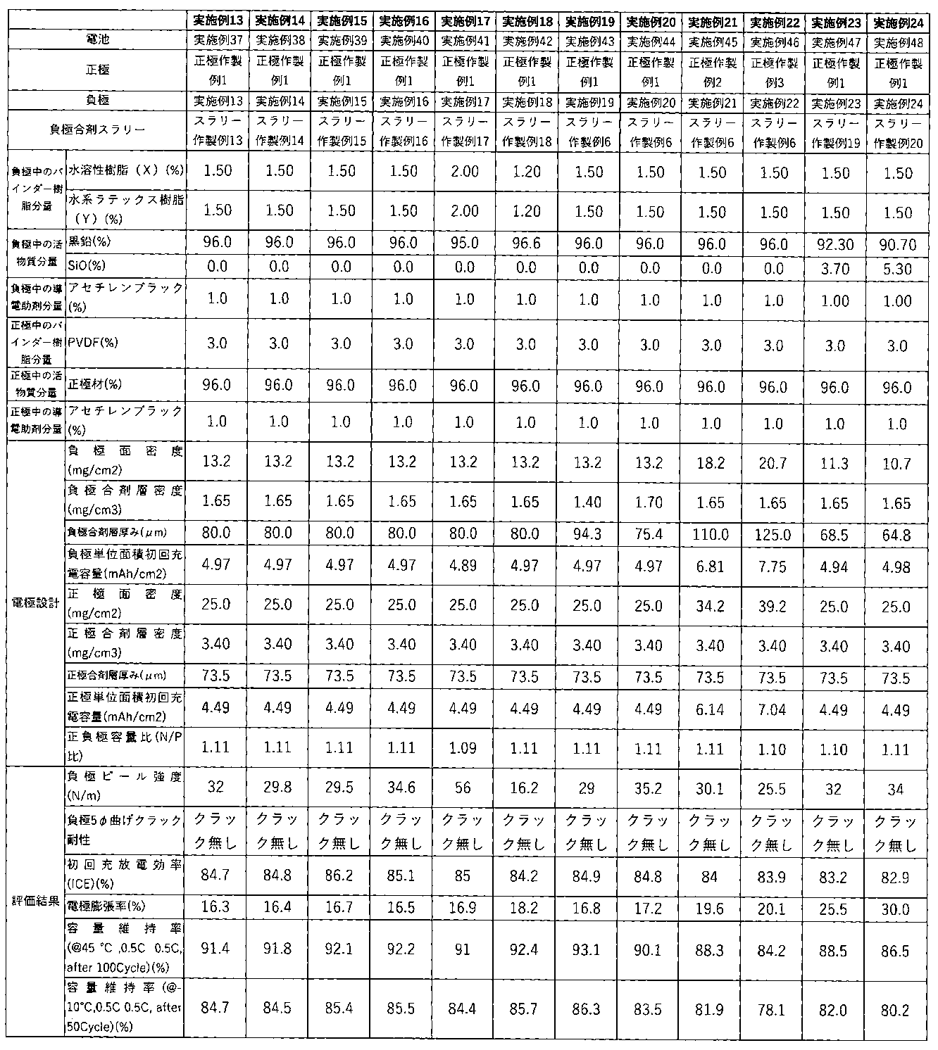
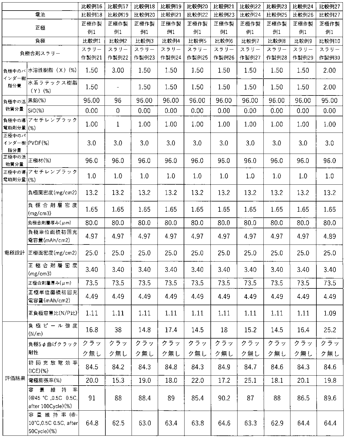
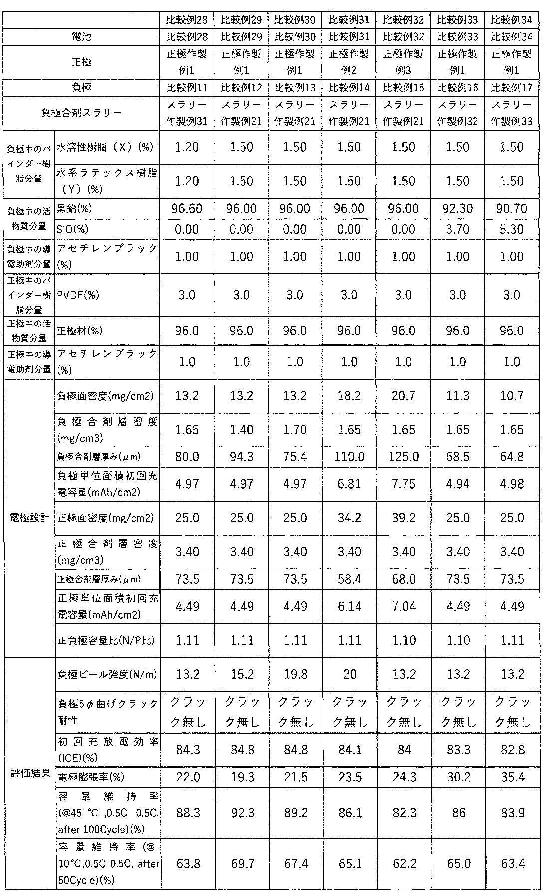
Claims (17)
- 水酸基含有モノマー(a)及び酸基含有モノマー(b)を必須成分とする共重合体を含む水溶性樹脂(X)と、水系ラテックス樹脂(Y)と、を含む負極バインダー組成物であって、
水系GPC測定装置を用いて測定したときの前記共重合体の重量平均分子量が700,000以上であり、且つ前記共重合体の乾燥フィルムを45℃のカーボネート系混合溶剤(EC(エチレンカーボネート)/DEC(ジエチレンカーボネート)=50/50(wt))に72時間浸漬させた後の膨潤率が0~10重量%である負極バインダー組成物。 - 前記水酸基含有モノマー(a)が、2-ヒドロキシエチルアクリレート、2-ヒドロキシプロピルアクリレート、3-ヒドロキシプロピルアクリレート、2-ヒドロキシブチルアクリレート、4-ヒドロキシブチルアクリレート、2-ヒドロキシエチルメタクリレート、2-ヒドロキシプロピルメタクリレート、3-ヒドロキシプロピルメタクリレート、2-ヒドロキシブチルメタクリレート、及び4-ヒドロキシブチルメタクリレートからなる群のうちいずれか1種以上である請求項1に記載の負極バインダー組成物。
- 前記酸基含有モノマー(b)が、塩基性組成物若しくは軽金属塩で中和されたものである請求項1に記載の負極バインダー組成物。
- 前記酸基含有モノマー(b)が、アクリル酸、メタクリル酸、マレイン酸、モノメチルマレイン酸、2-カルボキシエチルアクリレート、2-カルボキシエチルメタクリレート、マレイン酸、及びイタコン酸からなる群のうちいずれか1種以上である請求項1に記載の負極バインダー組成物。
- 前記水溶性樹脂(X)が、更にアクリルアミド、メタクリルアミド、N-メチルアクリルアミド、N,N-ジメチルアクリルアミド、及びN-ヒドロキシメチルアクリルアミドからなる群のうちいずれか1種以上を含む請求項1に記載の負極バインダー組成物。
- 前記水溶性樹脂(X)全量に対する、前記水酸基含有モノマー(a)と前記酸基含有モノマー(b)由来の樹脂成分の合計含有量が5~80重量%である請求項1に記載の負極バインダー組成物。
- 前記のアクリルアミド、メタクリルアミド、N-メチルアクリルアミド、N,N-ジメチルアクリルアミド、及びN-ヒドロキシメチルアクリルアミドからなる群のうちいずれか1種以上の含有量が0~80重量%である請求項1に記載の負極バインダー組成物。
- 前記水系ラテックス樹脂(Y)が、SBR、スチレンアクリレート共重合体、及びアクリレート共重合体のうちいずれか1種以上である請求項1に記載の負極バインダー組成物。
- 前記スチレンアクリレート共重合体が、ブチルアクリレートである請求項8に記載の負極バインダー組成物。
- 前記スチレンアクリレート共重合体全量における、スチレン単量体由来の構成単位の含有量が40~60重量%、且つブチルアクリレート単量体由来の構成単位の含有量が20~40重量%である請求項9に記載の負極バインダー組成物。
- 請求項1~10のいずれか一項に記載の負極バインダー組成物を成分として含む負極。
- 水溶性樹脂(X)由来の成分と、水系ラテックス樹脂(Y)由来の成分の合計含有量が、1.5重量%以上5.5重量%以下である請求項11に記載の負極。
- 黒鉛質主体の材料を主活物質として含み、更に負極の体積密度が1.4g/cm3以上である請求項11に記載の負極。
- 合剤層の厚みが80μm以上である請求項11に記載の負極。
- 黒鉛質主体の材料とシリコンを含有する材料の少なくとも2種以上の混合活物質を含む請求項11に記載の負極。
- 請求項11に記載の負極から構成される二次電池。
- 少なくとも活物質と前記水溶性樹脂(X)から成る水系スラリーを固練りする工程と、その後に固形分濃度を下げて前記水系ラテックス樹脂(Y)を混合する工程を有する請求項1~10のいずれか一項に記載の負極バインダー組成物の製造方法。
Priority Applications (3)
| Application Number | Priority Date | Filing Date | Title |
|---|---|---|---|
| JP2023533710A JP7359337B1 (ja) | 2022-04-12 | 2023-03-09 | 負極バインダー組成物およびその製造方法、負極、及び二次電池 |
| US18/851,785 US20250201847A1 (en) | 2022-04-12 | 2023-03-09 | Negative electrode binder composition and method for producing the same, negative electrode, and secondary battery |
| CN202380026631.8A CN119072802A (zh) | 2022-04-12 | 2023-03-09 | 负极粘合剂组合物及其制造方法、负极、以及二次电池 |
Applications Claiming Priority (2)
| Application Number | Priority Date | Filing Date | Title |
|---|---|---|---|
| JP2022065647 | 2022-04-12 | ||
| JP2022-065647 | 2022-04-12 |
Publications (1)
| Publication Number | Publication Date |
|---|---|
| WO2023199657A1 true WO2023199657A1 (ja) | 2023-10-19 |
Family
ID=88329344
Family Applications (1)
| Application Number | Title | Priority Date | Filing Date |
|---|---|---|---|
| PCT/JP2023/008947 Ceased WO2023199657A1 (ja) | 2022-04-12 | 2023-03-09 | 負極バインダー組成物およびその製造方法、負極、及び二次電池 |
Country Status (2)
| Country | Link |
|---|---|
| TW (1) | TW202405120A (ja) |
| WO (1) | WO2023199657A1 (ja) |
Citations (3)
| Publication number | Priority date | Publication date | Assignee | Title |
|---|---|---|---|---|
| JP2014089834A (ja) * | 2012-10-29 | 2014-05-15 | Nippon Zeon Co Ltd | リチウムイオン二次電池負極用スラリー組成物及びその製造方法、リチウムイオン二次電池用負極、並びにリチウムイオン二次電池 |
| JP2016171074A (ja) * | 2015-03-13 | 2016-09-23 | 日本ゼオン株式会社 | リチウムイオン二次電池電極用バインダー組成物、リチウムイオン二次電池電極用スラリー組成物、リチウムイオン二次電池用電極およびリチウムイオン二次電池 |
| WO2019159706A1 (ja) * | 2018-02-19 | 2019-08-22 | 日本ゼオン株式会社 | 非水系二次電池電極用バインダー組成物、非水系二次電池電極用スラリー組成物、非水系二次電池用電極および非水系二次電池 |
-
2023
- 2023-03-09 WO PCT/JP2023/008947 patent/WO2023199657A1/ja not_active Ceased
- 2023-03-16 TW TW112109779A patent/TW202405120A/zh unknown
Patent Citations (3)
| Publication number | Priority date | Publication date | Assignee | Title |
|---|---|---|---|---|
| JP2014089834A (ja) * | 2012-10-29 | 2014-05-15 | Nippon Zeon Co Ltd | リチウムイオン二次電池負極用スラリー組成物及びその製造方法、リチウムイオン二次電池用負極、並びにリチウムイオン二次電池 |
| JP2016171074A (ja) * | 2015-03-13 | 2016-09-23 | 日本ゼオン株式会社 | リチウムイオン二次電池電極用バインダー組成物、リチウムイオン二次電池電極用スラリー組成物、リチウムイオン二次電池用電極およびリチウムイオン二次電池 |
| WO2019159706A1 (ja) * | 2018-02-19 | 2019-08-22 | 日本ゼオン株式会社 | 非水系二次電池電極用バインダー組成物、非水系二次電池電極用スラリー組成物、非水系二次電池用電極および非水系二次電池 |
Also Published As
| Publication number | Publication date |
|---|---|
| TW202405120A (zh) | 2024-02-01 |
Similar Documents
| Publication | Publication Date | Title |
|---|---|---|
| JP7170330B2 (ja) | 二次電池用負極及び二次電池 | |
| US12315931B2 (en) | Negative electrode and secondary battery including same | |
| JP2971451B1 (ja) | リチウム二次電池 | |
| JP2013008526A (ja) | リチウムイオン二次電池用負極材、リチウムイオン二次電池用負極及びリチウムイオン二次電池 | |
| JP2003077463A (ja) | リチウム二次電池及びその製造方法 | |
| CN101981728A (zh) | 二次电池用正极板、其制造方法及具有该正极板的二次电池 | |
| CN108780892A (zh) | 非水系二次电池电极用粘结剂组合物、非水系二次电池电极用浆料组合物、非水系二次电池用电极及非水系二次电池 | |
| WO2019156031A1 (ja) | リチウムイオン二次電池用電極、その製造方法、及びリチウムイオン二次電池 | |
| JP7311059B2 (ja) | 負極バインダー組成物、負極、及び二次電池 | |
| EP4163310B1 (en) | Nonaqueous secondary battery electrode binder and nonaqueous secondary battery electrode slurry | |
| CN117413379B (zh) | 正极极片、电化学装置和电子装置 | |
| CN113646946A (zh) | 二次电池 | |
| CN114930577A (zh) | 负极活性材料、以及包含该负极活性材料的负极和二次电池 | |
| JP2009135010A (ja) | 非水電解液二次電池 | |
| JP2013229107A (ja) | レート特性、サイクル特性に優れ、高エネルギー密度であっても高い安全性を有するリチウムイオン二次電池 | |
| JP7359337B1 (ja) | 負極バインダー組成物およびその製造方法、負極、及び二次電池 | |
| JP4601273B2 (ja) | 非水溶媒系二次電池 | |
| CN112740439A (zh) | 锂离子二次电池及其制造方法、以及锂离子二次电池用正极 | |
| JP2004273281A (ja) | 非水二次電池 | |
| WO2023199657A1 (ja) | 負極バインダー組成物およびその製造方法、負極、及び二次電池 | |
| JP7245100B2 (ja) | リチウムイオン二次電池 | |
| JPH10334888A (ja) | 非水電解質二次電池用負極および該負極を使用した非水電解質二次電池 | |
| JP3512543B2 (ja) | 非水電解液二次電池 | |
| JPH0927313A (ja) | 非水電解液二次電池 | |
| JP2025086528A (ja) | リチウムイオン二次電池用負極スラリー組成物、リチウムイオン二次電池用負極、及びリチウムイオン二次電池 |
Legal Events
| Date | Code | Title | Description |
|---|---|---|---|
| WWE | Wipo information: entry into national phase |
Ref document number: 2023533710 Country of ref document: JP |
|
| 121 | Ep: the epo has been informed by wipo that ep was designated in this application |
Ref document number: 23788079 Country of ref document: EP Kind code of ref document: A1 |
|
| WWE | Wipo information: entry into national phase |
Ref document number: 202380026631.8 Country of ref document: CN |
|
| WWE | Wipo information: entry into national phase |
Ref document number: 18851785 Country of ref document: US |
|
| NENP | Non-entry into the national phase |
Ref country code: DE |
|
| 122 | Ep: pct application non-entry in european phase |
Ref document number: 23788079 Country of ref document: EP Kind code of ref document: A1 |
|
| WWP | Wipo information: published in national office |
Ref document number: 18851785 Country of ref document: US |