WO2023195133A1 - 車両の制御方法及び車両の制御装置 - Google Patents
車両の制御方法及び車両の制御装置 Download PDFInfo
- Publication number
- WO2023195133A1 WO2023195133A1 PCT/JP2022/017283 JP2022017283W WO2023195133A1 WO 2023195133 A1 WO2023195133 A1 WO 2023195133A1 JP 2022017283 W JP2022017283 W JP 2022017283W WO 2023195133 A1 WO2023195133 A1 WO 2023195133A1
- Authority
- WO
- WIPO (PCT)
- Prior art keywords
- shift
- switch
- power
- shift position
- button
- Prior art date
- Legal status (The legal status is an assumption and is not a legal conclusion. Google has not performed a legal analysis and makes no representation as to the accuracy of the status listed.)
- Ceased
Links
Images
Classifications
-
- B—PERFORMING OPERATIONS; TRANSPORTING
- B60—VEHICLES IN GENERAL
- B60K—ARRANGEMENT OR MOUNTING OF PROPULSION UNITS OR OF TRANSMISSIONS IN VEHICLES; ARRANGEMENT OR MOUNTING OF PLURAL DIVERSE PRIME-MOVERS IN VEHICLES; AUXILIARY DRIVES FOR VEHICLES; INSTRUMENTATION OR DASHBOARDS FOR VEHICLES; ARRANGEMENTS IN CONNECTION WITH COOLING, AIR INTAKE, GAS EXHAUST OR FUEL SUPPLY OF PROPULSION UNITS IN VEHICLES
- B60K20/00—Arrangement or mounting of change-speed gearing control devices in vehicles
- B60K20/02—Arrangement or mounting of change-speed gearing control devices in vehicles of initiating means
-
- F—MECHANICAL ENGINEERING; LIGHTING; HEATING; WEAPONS; BLASTING
- F16—ENGINEERING ELEMENTS AND UNITS; GENERAL MEASURES FOR PRODUCING AND MAINTAINING EFFECTIVE FUNCTIONING OF MACHINES OR INSTALLATIONS; THERMAL INSULATION IN GENERAL
- F16H—GEARING
- F16H59/00—Control inputs to control units of change-speed- or reversing-gearings for conveying rotary motion
- F16H59/02—Selector apparatus
- F16H59/08—Range selector apparatus
- F16H59/10—Range selector apparatus comprising levers
- F16H59/105—Range selector apparatus comprising levers consisting of electrical switches or sensors
-
- F—MECHANICAL ENGINEERING; LIGHTING; HEATING; WEAPONS; BLASTING
- F16—ENGINEERING ELEMENTS AND UNITS; GENERAL MEASURES FOR PRODUCING AND MAINTAINING EFFECTIVE FUNCTIONING OF MACHINES OR INSTALLATIONS; THERMAL INSULATION IN GENERAL
- F16H—GEARING
- F16H61/00—Control functions within control units of change-speed- or reversing-gearings for conveying rotary motion ; Control of exclusively fluid gearing, friction gearing, gearings with endless flexible members or other particular types of gearing
- F16H61/12—Detecting malfunction or potential malfunction, e.g. fail safe ; Circumventing or fixing failures
-
- F—MECHANICAL ENGINEERING; LIGHTING; HEATING; WEAPONS; BLASTING
- F16—ENGINEERING ELEMENTS AND UNITS; GENERAL MEASURES FOR PRODUCING AND MAINTAINING EFFECTIVE FUNCTIONING OF MACHINES OR INSTALLATIONS; THERMAL INSULATION IN GENERAL
- F16H—GEARING
- F16H59/00—Control inputs to control units of change-speed- or reversing-gearings for conveying rotary motion
- F16H59/68—Inputs being a function of gearing status
Definitions
- the present invention relates to a vehicle control method and control device that selects a shift position by operating a switch.
- a vehicle shift device that selects a vehicle shift position by operating a switch is conventionally known.
- a shift device that selects a shift position by operating a switch it is necessary to consider safety in determining which switch is assumed to have been operated when a plurality of switches are operated at the same time.
- Patent Document 1 if multiple push buttons including a push button for selecting a neutral position are pressed at the same time, it is determined that the push button for selecting a neutral position has been pressed, and the risk of driving operation is prevented. Techniques to avoid this have been disclosed.
- Patent Documents 2 and 3 disclose that when a plurality of switch operations including a switch operation for selecting a parking position are performed at the same time, it is determined that the operation for selecting a parking position has been performed to avoid dangers in driving operations. The technology has been disclosed.
- the gear shift may differ from the driver's intention. It is controlled by the position.
- the gear shift may be different from the driver's intention. It is controlled by the position.
- the vehicle of the present invention has two states: a state in which the switch is operated in a shift position in which the power of the drive source is not transmitted to the drive wheels, and a state in which the switch in the shift position in which power from the drive source is transmitted to the drive wheels is operated. If there is overlap, select a shift position where the power of the drive source is not transmitted to the drive wheels, then release the switch at the shift position where power of the drive source is not transmitted to the drive wheels, and the power of the drive source is transferred to the drive wheels. When the switch for the shift position that is transmitted to the wheels is switched to the operated state, the shift position in which the power of the drive source is not transmitted to the drive wheels is maintained.
- the present invention it is possible to prevent the vehicle from starting erroneously, and it is also possible to suppress the selection of a shift range different from the driver's intention.
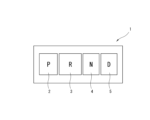
- FIG. 2 is an explanatory diagram schematically showing a gear shift operating device of a vehicle.
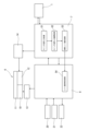
- FIG. 1 is an explanatory diagram schematically showing a system configuration of a vehicle to which the present invention is applied.
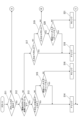
- 5 is a flowchart showing the flow of processing for determining a shift position.
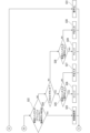
- 5 is a flowchart showing the flow of processing for determining a shift position.
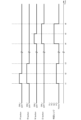
- 5 is a timing chart showing the relationship between button operations on the speed change operating device and shift positions selected as a result of the button operations.
- FIG. 1 is an explanatory diagram schematically showing a gear shift operating device 1 for a vehicle to which the present invention is applied.
- the gear shift operating device 1 has an input unit (switch) such as a push button switch or a touch panel, and the driver can change the shift position (shift range) by operating (pressing or touching) this input unit with a finger or the like. It is a choice.
- the shift operating device 1 corresponds to a shift operating section, and includes the same number of push-button switches that correspond one-to-one to the shift positions as the number of selectable shift positions.
- the speed change operation device 1 has push button switches such as a P range button (P button) 2, an R range button (R button) 3, an N range button (N button) 4, and a D range button (D button) 5. have.
- the P range button 2 corresponds to a parking position where the power of the drive source is not transmitted to the drive wheels, and is operated (pressed) when selecting the parking position.
- the R range button 3 corresponds to a reverse position for reversing where the power of the drive source is transmitted to the drive wheels, and is operated (pressed) when selecting the reverse position.
- the N range button 4 corresponds to a neutral position in which the power of the drive source is not transmitted to the drive wheels, and is operated (pressed) when selecting the neutral position.
- the D range button 5 corresponds to a forward drive position where power from the drive source is transmitted to the drive wheels, and is operated (pressed) when selecting the drive position.
- the arrangement of the push buttons in the shift operating device 1 is not limited to the order shown in FIG. 1 (the order of P, R, N, and D from the right side in FIG. 1), and can be changed as appropriate.
- FIG. 2 is an explanatory diagram schematically showing the system configuration of a vehicle to which the present invention is applied.
- FIG. 2 shows a case where the vehicle to which the present invention is applied is a hybrid vehicle.
- the vehicle includes a drive unit 6, a shift controller 7, and a vehicle controller 8.
- the drive unit 6 includes a travel motor 10 as a drive source that drives the drive wheels of the vehicle, a speed reducer 11 that decelerates the rotation of the travel motor 10, and a park lock mechanism that mechanically restrains the rotation of the speed reducer 11. 12.
- the running motor 10 is a direct drive source for the vehicle, and is supplied with AC power from a battery (not shown) or the like via an inverter 13.
- the traveling motor 10 is, for example, a synchronous motor using a permanent magnet in its rotor. Further, the traveling motor 10 functions as a generator when the vehicle is decelerated. That is, the traveling motor 10 is a generator motor that can charge the battery using regenerated energy during vehicle deceleration as electric power.
- the speed reducer 11 meshes a plurality of gears to reduce the rotation of the travel motor 10 and increases the motor torque to ensure travel drive torque.
- the park lock mechanism 12 switches between a park lock state in which the rotation of the gear inside the reducer 11 is restricted, and a park lock release state in which the rotation of the gear inside the reducer 11 is allowed.
- the park lock mechanism 12 can be switched between a park lock state and a park lock release state by mechanical operation caused by actuation of a park lock actuator 14.
- the mechanical operation is, for example, moving a claw-like member back and forth to prevent the gear from rotating when it is caught on the gear of the reducer 11.
- the result of the operation of the shift operating device 1 is input to the shift controller 7.
- the shift controller 7 sequentially performs a switch signal input process S1, a switch signal input arbitration process S2, and a target range determination process S3 based on the input from the shift operating device 1, and selects a shift position.
- the shift controller 7 gives top priority to the operation of the P range button 2, and then to the operation of the N range button 4, when a plurality of switches of the speed change operation device 1 are pressed redundantly. .
- the shift controller 7 basically assumes that the operation of the D range button 5 and the R range button 3 are not prioritized over the operation of the P range button 2 and the N range button 4.
- a signal from a switch operated by the speed change operating device 1 is processed.
- a failure signal of the speed change operation device 1 is also processed.
- the switch signal input arbitration process S2 it is determined which push-button switch of the speed change operation device 1 is assumed to have been operated in response to the input from the speed change operation device 1. Specifically, for example, when a plurality of switches of the speed change operating device 1 are pressed in duplicate, it is determined which switch has been operated.
- the target range determination process S3 it is determined which shift position (shift range) to actually switch to.
- the determination result of the target range determination process S3 is transmitted to the vehicle controller 8.
- the vehicle controller 8 receives the determination result of the target range determination process S3 and performs a shift final determination process S4.
- the shift final determination process S4 it is determined whether the vehicle side can accept the determination result of the target range determination process S3. For example, if the state of the vehicle is such that the determination result of the target range determination process S3 cannot be accepted, the determination result of the target range determination process S3 is not accepted and the current shift position is maintained. Note that the result of the shift final determination process S4 is fed back to the shift controller 7.
- the shift controller 7 and the vehicle controller 8 correspond to a control section, and determine which shift position has been selected based on the operation result of the shift operation device 1, and control the vehicle based on the shift position determined to have been selected. Control.
- the shift controller 7 supplies a predetermined power to the park lock actuator 14 so that the park lock actuator 14 can obtain the desired drive output. do.
- the park lock actuator 14 operates the park lock mechanism 12.
- the vehicle controller 8 inputs the result of the final shift determination process S4 to the inverter 13. That is, information indicating which shift position of the vehicle is selected among the parking position, neutral position, drive position, and reverse position is input to the inverter 13.
- the inverter 13 determines the electric power to be supplied to the driving motor 10 based on a command from the vehicle controller 8.
- Battery charging and discharging information is input to the vehicle controller 8 from a battery controller 20 that manages charging and discharging of a battery that can supply power to the driving motor 10.
- Control information for the internal combustion engine is input to the vehicle controller 8 from an engine control unit 21 that controls the internal combustion engine that is driven to generate electric power to be supplied to the driving motor 10.
- the internal combustion engine drives a battery and a generator that generates electric power to be supplied to the internal combustion engine.
- the vehicle controller 8 outputs shift position information to a meter 22 that displays the shift position.
- 3 and 4 are flowcharts showing the flow of the process of determining the shift position, which is carried out in the switch signal input arbitration process S2 of the shift controller 7.
- step S11 it is determined whether or not there is a button input on the shift operating device 1. That is, in step S11, it is determined whether any button of the speed change operation device 1 has been operated (pressed). If it is determined in step S11 that a button input has been made, the process advances to step S12. If it is determined in step S11 that there is no button input, the process advances to step S31.
- step S12 it is determined whether or not a plurality of buttons on the speed change operation device 1 are being pressed simultaneously. That is, in step S12, it is determined whether or not a state in which a plurality of buttons of the speed change operating device 1 are operated overlaps. If it is determined in step S12 that a plurality of buttons are pressed simultaneously, the process advances to step S13. If it is determined in step S12 that a plurality of buttons are not pressed simultaneously, the process advances to step S17.
- step S13 it is determined whether the P range button 2 is included in the plurality of buttons being operated. If it is determined in step S13 that P range button 2 is included, the process advances to step S14. If it is determined in step S13 that P range button 2 is not included, the process advances to step S15.
- step S14 it is determined that the parking position has been selected as the shift position, and the current routine is ended.
- step S15 it is determined whether the previous switch input was from the P range button 2 or not. That is, in step S15, it is determined whether the previously determined shift position is the parking position. If the previously determined shift position is determined to be the parking position in step S15, the process advances to step S14. If it is determined in step S15 that the previously determined shift position is not the parking position, the process advances to step S16.
- step S16 it is determined that the neutral position has been selected as the shift position, and the current routine is ended.
- step S17 it is determined whether the button input is from the P range button 2 or not. If it is determined in step S17 that the button input is from P range button 2, the process advances to step S18. If it is determined in step S17 that the button input is not from the P range button 2, the process advances to step S19.
- step S18 it is determined that the parking position has been selected as the shift position, and the current routine is ended.
- step S19 it is determined whether the button input is from the N range button 4 or not. If it is determined in step S19 that the button input is from the N range button 4, the process advances to step S20. If it is determined in step S19 that the button input is not from the N range button 4, the process advances to step S22.
- step S20 it is determined whether the previous switch input was from the P range button 2 or not. That is, in step S20, it is determined whether the previously determined shift position is the parking position. If the previously determined shift position is determined to be the parking position in step S20, the process advances to step S18. If it is determined in step S20 that the previously determined shift position is not the parking position, the process advances to step S21.
- step S21 it is determined that the neutral position has been selected as the shift position, and the current routine is ended.
- step S22 it is determined whether the previous switch input included the P range button 2 or the N range button 4. That is, in step S22, it is determined whether the previously determined shift position is the parking position or neutral. If it is determined in step S22 that the previously determined shift position is the parking position or the neutral position, the process advances to step S23. If it is determined in step S22 that the previously determined shift position is not the parking position or the neutral position, the process advances to step S24.
- the previous switch input in step S22 includes a switch input corresponding to a shift position determined when a plurality of buttons on the shift operating device 1 are pressed at the same time.
- the previous switch input in step S22 is the switch input corresponding to this determined shift position. becomes.
- step S23 the previous value is held and the current routine is ended. That is, in step S23, the previously selected shift position is maintained and the current routine is ended.
- step S24 it is determined whether the button input is from the D range button 5 or not. If it is determined in step S24 that the button input is from the D range button 5, the process advances to step S25. If it is determined in step S24 that the button input is not from the D range button 5, the process advances to step S28.
- step S25 it is determined whether the previous switch input was no operation. That is, in step S25, it is determined whether the previous determination result is that there is no operation. If it is determined in step S25 that the previous determination was that there was no operation, the process advances to step S26. If it is determined in step S25 that the previous determination is not no operation, the process advances to step S27.
- An example of proceeding to step S27 is when the operation of the R range button 3 is completed (off) and the D range button 5 is operated (on) at the same time.
- step S26 it is determined that the drive position has been selected as the shift position, and the current routine is ended.
- step S27 it is determined that the input is undefined, and the current routine is ended.
- step S28 it is determined whether the previous switch input was no operation. That is, in step S28, it is determined whether the previous determination result is that there is no operation. If it is determined in step S28 that the previous determination was that there was no operation, the process advances to step S29. If it is determined in step S28 that the previous determination is not no operation, the process advances to step S30. An example of proceeding to step S30 is when the operation of the D range button 5 is completed (off) and the R range button 3 is operated (on) at the same time.
- step S29 it is determined that the reverse position has been selected as the shift position, and the current routine is ended.
- step S30 it is determined that the input is undefined, and the current routine is ended.
- step S31 it is determined that there is no operation, and the current routine is ended. That is, in step S31, it is determined that none of the buttons on the gear shift operating device 1 have been operated.
- FIG. 5 is a timing chart showing the relationship between the button operations of the shift operating device 1 and the shift position (determination range) selected by the determination in the switch signal input arbitration process S2.
- Time t1 is the timing when the P range button 2 and the R range button 3 are operated (pressed) and turned on.
- the shift controller 7 determines that the P range button 2 has been operated at time t1 according to the priority of button operations (steps S11 ⁇ S12 ⁇ S13 ⁇ S14 in the flowchart of FIG. 3). Therefore, the determination range becomes the parking position from time t1.
- Time t2 is the timing when the operation of the P range button 2 is completed (turned off).
- the R range button 3 which was turned on at the same time as the P range button 2, continues to remain on. Therefore, the shift controller 7 continues to determine the shift position as the parking position at time t2 (steps S11 ⁇ S12 ⁇ S17 ⁇ S19 ⁇ S22 ⁇ S23 in the flowcharts of FIGS. 3 and 4). Therefore, the determination range is maintained at the parking position even after time t2.
- Time t3 is the timing when the operation of the R range button 3 is completed (turned off).
- the shift controller 7 determines that there is no button input on the shift operating device 1 at time t3 (steps S11 ⁇ S31 in the flowcharts of FIGS. 3 and 4). Therefore, the determination range becomes the home position from time t3.
- the shift controller 7 sets the determination range to the home position (Home) when all the buttons of the shift operating device 1 are not operated (off state).
- the home position is a state in which no shift position such as a parking position, neutral position, drive position, or reverse position is selected.
- the shift controller 7 can switch to a new determination range when the determination range experiences the home position.
- Time t4 is the timing when the N range button 4 and the D range button 5 are operated (pressed) and turned on.
- the shift controller 7 determines that the N range button 4 has been operated at time t4 according to the priority of button operations (steps S11 ⁇ S12 ⁇ S13 ⁇ S15 ⁇ S16 in the flowchart of FIG. 3). Therefore, the determination range becomes the neutral position from time t4.
- Time t5 is the timing when the operation of the N range button 4 is completed (turned off). At this time, the D range button 5, which was turned on at the same time as the N range button 4, continues to remain on. Therefore, the shift controller 7 continues to determine that the shift position is the neutral position at time t5 (steps S11 ⁇ S12 ⁇ S17 ⁇ S19 ⁇ S22 ⁇ S23 in the flowcharts of FIGS. 3 and 4). Therefore, the determination range is maintained at the neutral position even after time t5.
- Time t6 is the timing when the operation of the D range button 5 is completed (turned off).
- the shift controller 7 determines that there is no button input on the shift operating device 1 at time t6 (steps S11 ⁇ S31 in the flowcharts of FIGS. 3 and 4). Therefore, the determination range becomes the home position from time t6.
- the state in which the P range button 2 or N range button 4 is operated and the state in which the D range button 5 or R range button 3 is operated overlap.
- select the parking position or neutral position and then switch to the state in which the P range button 2 or N range button 4 is released and the D range button 5 or R range button 3 is operated. maintain the park or neutral position.
- a switch in a vehicle to which the present invention is applied, there is a state in which a switch is operated in a shift position in which power from the drive source is not transmitted to the drive wheels, and a state in which a switch in a shift position in which power from the drive source is transmitted to the drive wheels is operated. If the same conditions overlap, select a shift position where the power from the drive source is not transmitted to the drive wheels, and then release the switch at the shift position where power from the drive source is not transmitted to the drive wheels and start driving. When only the switch at the shift position where the power of the drive source is transmitted to the drive wheels is operated, the shift position where the power of the drive source is not transmitted to the drive wheels is maintained.
- step S23 if the routine leading to step S23 is experienced after (immediately after) the routine leading to step S14 or step S16, the shift position where the power of the drive source, which is the previous value, is not transmitted to the drive wheels is maintained. do.
- the vehicle can prevent erroneous starting and also suppress selection of a shift position (shift range) that is different from the driver's intention.
- the vehicle In the vehicle to which the present invention is applied, if the state in which the P range button 2 or N range button 4 is operated and the state in which the D range button 5 or R range button 3 is operated overlap, the vehicle is in the parking position. Alternatively, it is assumed that the neutral position is selected.
- a shift position where the power of the drive source is not transmitted to the drive wheels is selected.
- the drive position or reverse position is changed. It is determined that it has been selected.
- the power of the drive source is transferred to the drive wheels after the shift position is switched from a selected state where the power of the drive source is transmitted to the drive wheels to a state where the shift position is not selected. If the switch for the shift position where the power is transmitted to the wheels is operated, it is determined that the shift position where the power of the drive source is transmitted to the drive wheels has been selected.
- step S26 or step S29 the routine from step S26 or step S29 to step S31.
- the drive position or reverse position is selected.
- the vehicle to which the present invention is applied can be moved to the drive position or reverse position. is determined to have been selected.
- the power of the drive source is transferred to the drive wheels after the switch is switched from a state where the shift position is maintained in which the power of the drive source is not transmitted to the drive wheels to a state where the switch is not operated.
- the shift position switch is operated, the shift position at which the power of the drive source is transmitted to the drive wheels is selected.
- step S23 is experienced, and the shift position where the power of the drive source, which is the previous value, is not transmitted to the drive wheels is maintained.
- the drive position or reverse position is selected.
- the shift controller 7 maintains the driving state. good. Specifically, when the R range button 3 is operated (pressed) and the determination range is in the reverse position, the P range button is operated (pressed), and the R range button 3 is operated. If the operation of the P range button 2 becomes redundant, the determination of the reverse position may be maintained.
- the vehicle can avoid a reduction in safety caused by changing the shift position to a position where power is not transmitted to the drive wheels while the vehicle is moving forward or backward.
- the present invention is also applicable to vehicles whose drive wheels are driven by an internal combustion engine.
- the drive unit 6 is composed of an internal combustion engine, a transmission, etc.
- the transmission control unit carries out the processes from the switch signal input process S1 to the final shift determination process S4, and the inverter 13 is omitted.
- the shift controller 7 and the vehicle controller 8 may be configured as one controller.
- the shift operation device 1 may perform the switch signal input arbitration process S2.
- the embodiments described above relate to a vehicle control method and a vehicle control device.
Landscapes
- Engineering & Computer Science (AREA)
- General Engineering & Computer Science (AREA)
- Mechanical Engineering (AREA)
- Chemical & Material Sciences (AREA)
- Combustion & Propulsion (AREA)
- Transportation (AREA)
- Control Of Transmission Device (AREA)
- Arrangement Or Mounting Of Control Devices For Change-Speed Gearing (AREA)
Priority Applications (5)
| Application Number | Priority Date | Filing Date | Title |
|---|---|---|---|
| US18/854,186 US12552248B2 (en) | 2022-04-07 | 2022-04-07 | Control method for vehicle and control device for vehicle |
| PCT/JP2022/017283 WO2023195133A1 (ja) | 2022-04-07 | 2022-04-07 | 車両の制御方法及び車両の制御装置 |
| JP2024513646A JP7694814B2 (ja) | 2022-04-07 | 2022-04-07 | 車両の制御方法及び車両の制御装置 |
| CN202280093995.3A CN118946751A (zh) | 2022-04-07 | 2022-04-07 | 车辆的控制方法以及车辆的控制装置 |
| EP22936532.5A EP4506199A1 (en) | 2022-04-07 | 2022-04-07 | Control method for vehicle and control device for vehicle |
Applications Claiming Priority (1)
| Application Number | Priority Date | Filing Date | Title |
|---|---|---|---|
| PCT/JP2022/017283 WO2023195133A1 (ja) | 2022-04-07 | 2022-04-07 | 車両の制御方法及び車両の制御装置 |
Publications (1)
| Publication Number | Publication Date |
|---|---|
| WO2023195133A1 true WO2023195133A1 (ja) | 2023-10-12 |
Family
ID=88242758
Family Applications (1)
| Application Number | Title | Priority Date | Filing Date |
|---|---|---|---|
| PCT/JP2022/017283 Ceased WO2023195133A1 (ja) | 2022-04-07 | 2022-04-07 | 車両の制御方法及び車両の制御装置 |
Country Status (5)
| Country | Link |
|---|---|
| US (1) | US12552248B2 (https=) |
| EP (1) | EP4506199A1 (https=) |
| JP (1) | JP7694814B2 (https=) |
| CN (1) | CN118946751A (https=) |
| WO (1) | WO2023195133A1 (https=) |
Citations (4)
| Publication number | Priority date | Publication date | Assignee | Title |
|---|---|---|---|---|
| JPS60167843U (ja) | 1984-04-17 | 1985-11-07 | 三菱自動車工業株式会社 | 押ボタン式自動変速機における複数押ボタンチエツク装置 |
| JP2010100193A (ja) * | 2008-10-24 | 2010-05-06 | Suzuki Motor Corp | シフトセレクトシステム |
| JP2014031143A (ja) * | 2012-08-06 | 2014-02-20 | Tokai Rika Co Ltd | シフト装置 |
| JP2016113071A (ja) | 2014-12-17 | 2016-06-23 | マツダ株式会社 | 車両用シフト装置 |
Family Cites Families (4)
| Publication number | Priority date | Publication date | Assignee | Title |
|---|---|---|---|---|
| JPS60167843A (ja) | 1984-02-09 | 1985-08-31 | Kurashiki Kikai Kk | スクラップの巻き取り機 |
| JPH0217265A (ja) | 1988-07-05 | 1990-01-22 | Iseki & Co Ltd | 押ボタン型電子変速機の制御装置 |
| KR101740590B1 (ko) * | 2015-06-15 | 2017-05-26 | 에스엘 주식회사 | 차량용 변속 장치 |
| KR102238050B1 (ko) * | 2015-06-24 | 2021-04-08 | 현대자동차주식회사 | 버튼 타입 전자식 변속시스템 |
-
2022
- 2022-04-07 US US18/854,186 patent/US12552248B2/en active Active
- 2022-04-07 WO PCT/JP2022/017283 patent/WO2023195133A1/ja not_active Ceased
- 2022-04-07 JP JP2024513646A patent/JP7694814B2/ja active Active
- 2022-04-07 CN CN202280093995.3A patent/CN118946751A/zh active Pending
- 2022-04-07 EP EP22936532.5A patent/EP4506199A1/en not_active Withdrawn
Patent Citations (4)
| Publication number | Priority date | Publication date | Assignee | Title |
|---|---|---|---|---|
| JPS60167843U (ja) | 1984-04-17 | 1985-11-07 | 三菱自動車工業株式会社 | 押ボタン式自動変速機における複数押ボタンチエツク装置 |
| JP2010100193A (ja) * | 2008-10-24 | 2010-05-06 | Suzuki Motor Corp | シフトセレクトシステム |
| JP2014031143A (ja) * | 2012-08-06 | 2014-02-20 | Tokai Rika Co Ltd | シフト装置 |
| JP2016113071A (ja) | 2014-12-17 | 2016-06-23 | マツダ株式会社 | 車両用シフト装置 |
Also Published As
| Publication number | Publication date |
|---|---|
| CN118946751A (zh) | 2024-11-12 |
| US12552248B2 (en) | 2026-02-17 |
| EP4506199A1 (en) | 2025-02-12 |
| JP7694814B2 (ja) | 2025-06-18 |
| JPWO2023195133A1 (https=) | 2023-10-12 |
| US20250242689A1 (en) | 2025-07-31 |
Similar Documents
| Publication | Publication Date | Title |
|---|---|---|
| JP3706068B2 (ja) | ハイブリッド車の推進力を制御する方法およびシステム | |
| US5984828A (en) | Control methods for a shift by wire vehicle transmission | |
| EP2949529A1 (en) | Controller of hybrid vehicle | |
| EP3259147B1 (en) | Hybrid vehicle | |
| EP2821306B1 (en) | Control device for hybrid vehicle | |
| JP2012035661A (ja) | 車両の制御装置 | |
| EP2826654A1 (en) | Generation control apparatus for hybrid vehicle | |
| JP5811262B2 (ja) | ハイブリッド車両の発進制御装置 | |
| JP4553388B2 (ja) | ハイブリッド電気自動車の制御装置 | |
| WO2023195133A1 (ja) | 車両の制御方法及び車両の制御装置 | |
| WO2023195136A1 (ja) | 車両の制御方法及び車両の制御装置 | |
| WO2023195135A1 (ja) | 車両の制御方法及び車両の制御装置 | |
| WO2023195134A1 (ja) | 車両の制御方法及び車両の制御装置 | |
| JPH11141665A (ja) | 自動車用変速機 | |
| JP2024071230A (ja) | 車両の制御装置 | |
| JP2019119373A (ja) | 車両の制御装置 | |
| JPS61102340A (ja) | 自動クラツチ制御装置 | |
| JPH1181388A (ja) | ホイールローダの走行駆動装置 | |
| JP2025164068A (ja) | 車両の制御装置 | |
| JP2019123451A (ja) | 車両の制御装置及び車両の制御方法 | |
| JP2025073024A (ja) | 車両用シフト装置 | |
| JP2018039430A (ja) | 動力伝達システムおよび制御装置 | |
| JPS62242172A (ja) | 歯車変速機 | |
| CN109591620A (zh) | 电动汽车控制方法及装置、电子设备及存储介质 | |
| JPH1198617A (ja) | 産業用車両の走行駆動装置 |
Legal Events
| Date | Code | Title | Description |
|---|---|---|---|
| 121 | Ep: the epo has been informed by wipo that ep was designated in this application |
Ref document number: 22936532 Country of ref document: EP Kind code of ref document: A1 |
|
| ENP | Entry into the national phase |
Ref document number: 2024513646 Country of ref document: JP Kind code of ref document: A |
|
| WWE | Wipo information: entry into national phase |
Ref document number: 202280093995.3 Country of ref document: CN |
|
| WWE | Wipo information: entry into national phase |
Ref document number: 18854186 Country of ref document: US |
|
| WWE | Wipo information: entry into national phase |
Ref document number: 2022936532 Country of ref document: EP |
|
| NENP | Non-entry into the national phase |
Ref country code: DE |
|
| ENP | Entry into the national phase |
Ref document number: 2022936532 Country of ref document: EP Effective date: 20241107 |
|
| WWW | Wipo information: withdrawn in national office |
Ref document number: 2022936532 Country of ref document: EP |
|
| WWP | Wipo information: published in national office |
Ref document number: 18854186 Country of ref document: US |
|
| WWG | Wipo information: grant in national office |
Ref document number: 18854186 Country of ref document: US |