WO2023189996A1 - 成形用樹脂組成物、封止構造体の製造方法および封止構造体 - Google Patents
成形用樹脂組成物、封止構造体の製造方法および封止構造体 Download PDFInfo
- Publication number
- WO2023189996A1 WO2023189996A1 PCT/JP2023/011406 JP2023011406W WO2023189996A1 WO 2023189996 A1 WO2023189996 A1 WO 2023189996A1 JP 2023011406 W JP2023011406 W JP 2023011406W WO 2023189996 A1 WO2023189996 A1 WO 2023189996A1
- Authority
- WO
- WIPO (PCT)
- Prior art keywords
- resin composition
- molding resin
- molding
- mass
- measured
- Prior art date
- Legal status (The legal status is an assumption and is not a legal conclusion. Google has not performed a legal analysis and makes no representation as to the accuracy of the status listed.)
- Ceased
Links
Images
Classifications
-
- C—CHEMISTRY; METALLURGY
- C08—ORGANIC MACROMOLECULAR COMPOUNDS; THEIR PREPARATION OR CHEMICAL WORKING-UP; COMPOSITIONS BASED THEREON
- C08K—Use of inorganic or non-macromolecular organic substances as compounding ingredients
- C08K3/00—Use of inorganic substances as compounding ingredients
- C08K3/01—Use of inorganic substances as compounding ingredients characterized by their specific function
- C08K3/013—Fillers, pigments or reinforcing additives
-
- C—CHEMISTRY; METALLURGY
- C08—ORGANIC MACROMOLECULAR COMPOUNDS; THEIR PREPARATION OR CHEMICAL WORKING-UP; COMPOSITIONS BASED THEREON
- C08L—COMPOSITIONS OF MACROMOLECULAR COMPOUNDS
- C08L63/00—Compositions of epoxy resins; Compositions of derivatives of epoxy resins
-
- H—ELECTRICITY
- H10—SEMICONDUCTOR DEVICES; ELECTRIC SOLID-STATE DEVICES NOT OTHERWISE PROVIDED FOR
- H10W—GENERIC PACKAGES, INTERCONNECTIONS, CONNECTORS OR OTHER CONSTRUCTIONAL DETAILS OF DEVICES COVERED BY CLASS H10
- H10W74/00—Encapsulations, e.g. protective coatings
- H10W74/01—Manufacture or treatment
-
- H—ELECTRICITY
- H10—SEMICONDUCTOR DEVICES; ELECTRIC SOLID-STATE DEVICES NOT OTHERWISE PROVIDED FOR
- H10W—GENERIC PACKAGES, INTERCONNECTIONS, CONNECTORS OR OTHER CONSTRUCTIONAL DETAILS OF DEVICES COVERED BY CLASS H10
- H10W74/00—Encapsulations, e.g. protective coatings
- H10W74/40—Encapsulations, e.g. protective coatings characterised by their materials
Definitions
- the present invention relates to a molding resin composition, a method for manufacturing a sealing structure, and a sealing structure.
- thermosetting resin In order to protect electronic components such as semiconductor devices or structures such as stators from the external environment, a method of sealing them using thermosetting resin is widely adopted.
- the transfer molding method using an epoxy resin as the sealing resin is excellent in economy and productivity, and is suitable for mass production, so it has become the mainstream of resin sealing.
- Patent Document 1 Japanese Unexamined Patent Publication No. 2003-284277.
- the document describes a rotating electric machine having a stator in which a plurality of coils are wound at predetermined intervals around a stator core made of a plurality of laminated electromagnetic steel sheets, a rotor that is rotatably held relative to the stator, and a cooling frame that fixes the stator.
- the present invention was made in view of the above circumstances, and is a molding resin that can be cured at low temperatures and that can improve the adhesion and waterproofness when sealing electronic components or structures such as stators.
- the purpose is to provide a composition.
- the following molding resin composition, method for manufacturing a sealing structure, and sealing structure are provided.
- a stator core fixed on the board having a plurality of slots formed in the circumferential direction, and a plurality of coils housed in the slots.
- a molding resin composition used Epoxy resin and one or both of a curing agent and a curing catalyst; an inorganic filler;
- Tg glass transition temperature
- Method 1 The above molding resin composition was molded into a test piece of 80 mm x 10 mm x 4 mm using a transfer molding machine at a mold temperature of 175°C, an injection pressure of 6.9 MPa, and a curing time of 90 seconds. Post-cure. Furthermore, using a thermomechanical analyzer, the coefficient of thermal expansion of the test piece obtained at a heating rate of 5° C./min is measured.
- the glass transition temperature (Tg) (° C.) of the cured product is calculated from the inflection point of the coefficient of thermal expansion.
- Tg glass transition temperature
- the phenolic resin curing agent contains one or more selected from the group consisting of a phenol novolac resin, a cresol novolak resin, a naphthol novolac resin, and a trisphenolmethane type phenolic resin.
- Method 3 The above resin composition for molding was placed into a spiral flow measurement mold according to ANSI/ASTM D 3123-72 using a low-pressure transfer molding machine under conditions of 175°C, injection pressure of 6.9 MPa, and pressure holding time of 3 minutes. The flow length is measured, and this is defined as the spiral flow (cm).
- Method 4 The above resin composition for molding was placed into a spiral flow measurement mold according to ANSI/ASTM D 3123-72 using a low-pressure transfer molding machine under conditions of 175°C, injection pressure of 6.9 MPa, and pressure holding time of 3 minutes. Inject with. The time from the start of injection until the molding resin composition hardens and ceases to flow is measured and is defined as gel time (seconds).
- gel time Seconds.
- Method 5 The above molding resin composition is injection molded using a low-pressure transfer molding machine under conditions of a mold temperature of 175° C., an injection pressure of 9.8 MPa, and a curing time of 3 minutes to obtain a molded article of 15 mm x 4 mm x 4 mm. Next, the obtained molded article is post-cured at 175° C. for 4 hours to prepare a test piece. Then, the obtained test piece was measured using a thermomechanical analyzer under the conditions of a measurement temperature range of 0°C to 400°C and a heating rate of 5°C/min, and the average linear expansion coefficient ⁇ 1 at 25-70°C (ppm/°C).
- Method 6 The above resin composition for molding is injection molded using a transfer molding machine under conditions of a mold temperature of 175° C., an injection pressure of 6.9 MPa, and a curing time of 90 seconds to obtain a molded article of 80 mm x 10 mm x 4 mm. Next, the obtained molded body is post-cured at 175° C. for 2 hours to obtain a test piece. Thermal diffusivity of the obtained test piece is measured using the laser flash method.
- a mold in a transfer molding machine includes a board on which electronic components are mounted, a stator core fixed on the board having a plurality of slots formed in the circumferential direction, and a plurality of coils accommodated in the slots.
- a step of arranging In the transfer molding method using the transfer molding machine, the molding resin composition according to any one of [1] to [15] above is used to mold the substrate in the mold, the stator core, and the coil.
- a step of obtaining a sealed structure by sealing and molding A method for manufacturing a sealed structure, comprising: [17] In the method for manufacturing a sealed structure according to [16] above, A method for manufacturing a sealed structure, wherein in the step of obtaining the sealed structure, sealing molding is performed at a temperature equal to or lower than the Tg of the cured product of the molding resin composition.
- a method for manufacturing a sealed structure in which a post-curing step is not performed as the step of obtaining the sealed structure.
- a molding resin composition that can be cured at low temperatures and can improve adhesion and waterproofness when sealing electronic components or structures such as stators.
- the molding resin composition of this embodiment includes a substrate on which electronic components are mounted, a stator core fixed on the substrate having a plurality of slots formed in the circumferential direction, and a stator core fixed on the substrate having a plurality of slots formed in the circumferential direction.
- a molding resin composition used for collectively sealing a coil the molding resin composition containing an epoxy resin, a curing catalyst, and an inorganic filler, the molding resin composition being heated at 140°C for 2 minutes.
- the cured product has a bending elastic modulus (according to JIS K6911:2006) at 25° C. of 0.1 GPa or more and 30 GPa or less.
- the molding resin composition of this embodiment includes a substrate on which electronic components are mounted, a stator core fixed on the substrate having a plurality of slots formed in the circumferential direction, and a stator core fixed on the substrate having a plurality of slots formed in the circumferential direction. It is used to seal the coil together.
- the method of using the moldable resin composition of this embodiment as a sealing material will be described in detail below.
- the molding resin composition of the present embodiment has a flexural modulus of elasticity (according to JIS K6911:2006) at 25°C of 0.1 GPa or more and 30 GPa or less in a cured product obtained by curing the molding resin composition at 140°C for 2 minutes. It is.
- the molding resin composition of this embodiment has a bending elastic modulus within the above numerical range, so it can be cured at low temperatures, and has excellent adhesion and waterproofing when sealing structures such as electronic parts or stators. can improve sex.
- the molding resin composition of this embodiment has a lower limit of flexural modulus at 25°C (JIS K6911 compliant: 2006) of 0.1 GPa in a cured product obtained by curing the molding resin composition at 140°C for 2 minutes.
- the above is preferably 1.0 GPa or more, more preferably 3.0 GPa or more, even more preferably 5.0 GPa or more, even more preferably 8.0 GPa or more, even more preferably 10.0 GPa or more, even more preferably 12.0 GPa. It is more preferably 13.0 GPa or more.
- the upper limit of the bending elastic modulus is 30 GPa or less, preferably 27.0 GPa or less, more preferably 24.0 GPa or less, even more preferably 21.0 GPa or less.
- the flexural modulus at 25° C. of the molding resin composition of this embodiment can be measured, for example, by the following method.
- the resin composition was injection molded under the conditions of a mold temperature of 140°C, an injection pressure of 9.8 MPa, and a curing time of 2 minutes to form a molded product with a length of 80 mm, width of 10 mm, and thickness of 4 mm. Obtained.
- the obtained molded product was heat-treated at 200° C. for 4 hours as a post-curing test piece, and the flexural modulus of elasticity can be measured at an ambient temperature of 25° C. according to JIS K 6911:2006.
- the low-pressure transfer molding machine for example, KTS-15 or KTS-30 (manufactured by Kotaki Seiki Co., Ltd.) can be used.
- epoxy resin examples of the epoxy resin used in the molding resin composition of the present embodiment include novolac type epoxy resins such as phenol novolac type epoxy resin, cresol novolac type epoxy resin, bisphenol A type epoxy resin, bisphenol F type epoxy resin, etc.
- Bisphenol type epoxy resin N,N-diglycidylaniline, N,N-diglycidyltoluidine, diaminodiphenylmethane type glycidylamine, aromatic glycidylamine type epoxy resin such as aminophenol type glycidylamine, hydroquinone type epoxy resin, biphenyl type Epoxy resin, stilbene type epoxy resin, trisphenolmethane type epoxy resin, trisphenolpropane type epoxy resin, alkyl-modified trisphenolmethane type epoxy resin, triazine core-containing epoxy resin, dicyclopentadiene-modified phenol type epoxy resin, naphthol type epoxy resin , naphthalene type epoxy resins, phenol aralkyl type epoxy resins having a phenylene and/or biphenylene skeleton, aralkyl type epoxy resins such as naphthol aralkyl type epoxy resins having a phenylene and/or biphenylene skeleton, aromatic epoxy resin
- the epoxy resin used in the molding resin composition of the present embodiment is one or two selected from the group consisting of phenol novolak epoxy resin, cresol novolac epoxy resin, and trisphenolmethane epoxy resin. It is preferable to include more than one species.
- the lower limit of the epoxy resin content in the molding resin composition of this embodiment is determined from the viewpoint of further improving the adhesion and waterproofness when sealing structures such as electronic parts or stators.
- the total solid content of the product is 100% by mass, preferably 3% by mass or more, more preferably 4% by mass or more, still more preferably 5% by mass or more, even more preferably 6% by mass or more, even more preferably 7% by mass. That's all.
- the upper limit of the content of the epoxy resin is preferably 40% when the entire solid content of the molding resin composition is 100% by mass. The content is at most 30% by mass, more preferably at most 20% by mass, even more preferably at most 15% by mass.
- the content of the epoxy resin in the molding resin composition of this embodiment is determined from the viewpoint of further improving the adhesion and waterproofness when sealing structures such as electronic parts or stators, and from the viewpoint of further improving the adhesiveness and waterproofness when sealing structures such as electronic parts or stators, and the From the viewpoint of obtaining a structure with excellent strength, when the entire solid content of the molding resin composition is 100% by mass, preferably 3% by mass or more and 40% by mass or less, more preferably 4% by mass or more and 30% by mass or less, More preferably, the content is 5% by mass or more and 20% by mass or less, still more preferably 6% by mass or more and 20% by mass or less, and even more preferably 7% by mass or more and 15% by mass or less.
- the molding resin composition of this embodiment contains one or both of a curing agent and a curing catalyst.
- the molding resin composition of this embodiment preferably contains a curing agent in order to three-dimensionally crosslink the epoxy resin, and when it contains a curing agent as an essential component, it more preferably contains a phenolic resin curing agent.
- phenolic resin curing agent examples include novolak type phenolic resins such as phenol novolac resin, cresol novolac resin, and naphthol novolac resin; polyfunctional phenolic resins such as trisphenolmethane type phenolic resin; terpene-modified phenolic resin, dicyclopentadiene Modified phenol resins such as modified phenol resins; phenol aralkyl resins having a phenylene skeleton and/or biphenylene skeleton; aralkyl type phenol resins such as naphthol aralkyl resins having a phenylene and/or biphenylene skeleton; bisphenol compounds such as bisphenol A, bisphenol F, etc. These may be used alone or in combination of two or more.
- novolak type phenolic resins such as phenol novolac resin, cresol novolac resin, and naphthol novolac resin
- polyfunctional phenolic resins such as trisphenolmethane type phenolic
- the phenolic resin curing agent is one or more selected from the group consisting of phenol novolac resin, cresol novolac resin, naphthol novolac resin, and trisphenolmethane type phenolic resin. including.
- a phenolic resin curing agent provides a good balance of flame resistance, moisture resistance, electrical properties, curability, storage stability, etc.
- the hydroxyl equivalent of the phenolic resin curing agent can be set to 90 g/eq or more and 250 g/eq or less.
- curing agents examples include polyaddition type curing agents, catalyst type curing agents, condensation type curing agents, and the like.
- polyaddition type curing agents include aliphatic polyamines such as diethylenetriamine (DETA), triethylenetetramine (TETA), and metaxylene diamine (MXDA), diaminodiphenylmethane (DDM), m-phenylenediamine (MPDA), and diaminodiamine.
- DETA diethylenetriamine
- TETA triethylenetetramine
- MXDA metaxylene diamine
- DDM diaminodiphenylmethane
- MPDA m-phenylenediamine
- aromatic polyamines such as diphenyl sulfone (DDS), polyamine compounds including dicyandiamide (DICY) and organic acid dihydrazide; alicyclic acid anhydrides such as hexahydrophthalic anhydride (HHPA) and methyltetrahydrophthalic anhydride (MTHPA) Acid anhydrides, including aromatic acid anhydrides such as trimellitic anhydride (TMA), pyromellitic anhydride (PMDA), and benzophenone tetracarboxylic acid (BTDA); polyphenolic compounds such as novolak-type phenolic resins and phenolic polymers Polymercaptan compounds such as polysulfide, thioester, and thioether; Isocyanate compounds such as isocyanate prepolymers and blocked isocyanates; Organic acids such as carboxylic acid-containing polyester resins.
- DDS diphenyl sulfone
- DIY dicyandiamide
- catalytic curing agents examples include tertiary amine compounds such as benzyldimethylamine (BDMA) and 2,4,6-trisdimethylaminomethylphenol (DMP-30); 2-methylimidazole, 2-ethyl-4 - Imidazole compounds such as methylimidazole (EMI24); Lewis acids such as BF 3 complex, and the like.
- BDMA benzyldimethylamine
- DMP-30 2,4,6-trisdimethylaminomethylphenol
- 2-methylimidazole, 2-ethyl-4 - Imidazole compounds such as methylimidazole (EMI24)
- Lewis acids such as BF 3 complex, and the like.
- condensation type curing agent examples include resol resins, urea resins such as methylol group-containing urea resins, and melamine resins such as methylol group-containing melamine resins.
- the lower limit of the content of the phenolic resin curing agent is preferably 20% by mass or more, more preferably 30% by mass or more, and even more preferably is 50% by mass or more, more preferably 70% by mass or more, even more preferably 90% by mass or more.
- the content of the phenolic resin curing agent is at least the above lower limit, good fluidity can be developed while maintaining curability at low temperatures.
- the upper limit of the content of the phenolic resin curing agent is not particularly limited, but is preferably 100% by mass or less based on the total curing agent.
- the lower limit of the total content of curing agents in the molding resin composition of the present embodiment is not particularly limited, it is preferably when the entire solid content of the molding resin composition is 100% by mass. is 0.8% by mass or more, more preferably 1% by mass or more, even more preferably 1.5% by mass or more, even more preferably 2% by mass or more, even more preferably 3% by mass or more, even more preferably 4% by mass or more. be. Good curability can be obtained when the total content of the curing agents is at least the above lower limit.
- the upper limit of the total content of curing agents in the molding resin composition is not particularly limited, but is preferably 12% by mass or less, more preferably 12% by mass or less, based on the entire molding resin composition. It is 10% by mass or less, more preferably 8% by mass or less.
- the phenol resin and epoxy resin used as a curing agent are equivalent to the equivalent ratio (EP)/(OH ) is preferably 0.8 or more and 1.6 or less.
- the equivalent ratio is within the above range, sufficient curing properties can be obtained when molding the resulting molding resin composition.
- the equivalent ratio may be adjusted as appropriate.
- the molding resin composition of this embodiment contains a curing catalyst as an essential component, it is preferable to use an imidazole-based compound as the curing catalyst used in the molding resin composition of this embodiment.
- imidazole compounds include imidazole, 2-methylimidazole, 2-undecylimidazole, 2-heptadecyl imidazole, 1,2-dimethylimidazole, 2-ethyl-4-methylimidazole, 2-phenylimidazole, 2-phenyl- 4-Methylimidazole, 1-benzyl-2-phenylimidazole, 1-benzyl-2-methylimidazole, 1-cyanoethyl-2-methylimidazole, 1-cyanoethyl-2-ethyl-4-methylimidazole, 1-cyanoethyl-2 - Imidazole compounds such as undecylimidazole, 1-cyanoethyl-2-phenylimidazole, 2-phenyl-4,5
- the content of the imidazole-based compound is preferably 0.01% by mass or more, more preferably 0.01% by mass or more when the entire solid content of the molding resin composition is 100% by mass.
- 03% by mass or more more preferably 0.05% by mass or more, even more preferably 0.1% by mass or more, even more preferably 0.3% by mass or more, still more preferably 0.5% by mass or more, even more preferably 1.0% by mass or more. It is 0% by mass or more.
- the content of the imidazole compound is preferably 2.0% by mass or less, more preferably 1.5% by mass or less, when the entire solid content of the molding resin composition is 100% by mass.
- curing catalysts include phosphorus atom-containing compounds such as organic phosphines, tetra-substituted phosphonium compounds, phosphobetaine compounds, adducts of phosphine compounds and quinone compounds, and adducts of phosphonium compounds and silane compounds; It can further contain one or more selected from amine curing catalysts other than imidazole compounds such as 1,8-diazabicyclo(5,4,0)undecene.
- organic phosphine examples include primary phosphines such as ethylphosphine and phenylphosphine; secondary phosphines such as dimethylphosphine and diphenylphosphine; and tertiary phosphines such as trimethylphosphine, triethylphosphine, tributylphosphine and triphenylphosphine.
- primary phosphines such as ethylphosphine and phenylphosphine
- secondary phosphines such as dimethylphosphine and diphenylphosphine
- tertiary phosphines such as trimethylphosphine, triethylphosphine, tributylphosphine and triphenylphosphine.
- Examples of the tetra-substituted phosphonium compound include compounds represented by the following general formula (4).
- P represents a phosphorus atom.
- R 4 , R 5 , R 6 and R 7 represent an aromatic group or an alkyl group.
- A represents an anion of an aromatic organic acid having at least one functional group selected from a hydroxyl group, a carboxyl group, and a thiol group in its aromatic ring.
- AH represents an aromatic organic acid having at least one functional group selected from a hydroxyl group, a carboxyl group, and a thiol group in an aromatic ring.
- x and y are numbers from 1 to 3
- z is a number from 0 to 3
- x y.
- the compound represented by general formula (4) can be obtained, for example, as follows, but is not limited thereto. First, a tetra-substituted phosphonium halide, an aromatic organic acid, and a base are mixed uniformly in an organic solvent, and an aromatic organic acid anion is generated in the solution system. Then, by adding water, the compound represented by general formula (4) can be precipitated.
- R 4 , R 5 , R 6 and R 7 bonded to the phosphorus atom are phenyl groups
- AH is a compound having a hydroxyl group in the aromatic ring, that is, a phenol.
- A is preferably an anion of the phenol.
- phenols include monocyclic phenols such as phenol, cresol, resorcinol, and catechol; condensed polycyclic phenols such as naphthol, dihydroxynaphthalene, and anthraquinol; and bisphenols such as bisphenol A, bisphenol F, and bisphenol S; Examples include polycyclic phenols such as phenylphenol and biphenol.
- Examples of the phosphobetaine compound used as a curing catalyst include a compound represented by the following general formula (5).
- P represents a phosphorus atom.
- R 8 represents an alkyl group having 1 to 3 carbon atoms, and R 9 represents a hydroxyl group.
- f is a number from 0 to 5
- g is a number from 0 to 3.
- the compound represented by general formula (5) can be obtained, for example, as follows. First, a triaromatic substituted phosphine, which is a tertiary phosphine, is brought into contact with a diazonium salt, and the diazonium group of the triaromatic substituted phosphine and the diazonium salt is substituted. However, it is not limited to this.
- Examples of the adduct of a phosphine compound and a quinone compound used as a curing catalyst include a compound represented by the following general formula (6).
- P represents a phosphorus atom.
- R 10 , R 11 and R 12 represent an alkyl group having 1 to 12 carbon atoms or an aryl group having 6 to 12 carbon atoms, and may be the same or different from each other.
- R 13 , R 14 and R 15 represent a hydrogen atom or a hydrocarbon group having 1 to 12 carbon atoms, and may be the same or different from each other, and R 14 and R 15 are bonded to form a cyclic structure. It's okay.
- Examples of phosphine compounds used in the adduct of a phosphine compound and a quinone compound include triphenylphosphine, tris(alkylphenyl)phosphine, tris(alkoxyphenyl)phosphine, trinaphthylphosphine, tris(benzyl)phosphine, etc. It is preferable that the substituent is substituted or has a substituent such as an alkyl group or an alkoxyl group, and examples of the substituent such as an alkyl group or an alkoxyl group include those having 1 to 6 carbon atoms. Triphenylphosphine is preferred from the viewpoint of availability.
- examples of the quinone compound used in the adduct of a phosphine compound and a quinone compound include benzoquinone and anthraquinones, and among them, p-benzoquinone is preferred from the viewpoint of storage stability.
- the adduct can be obtained by contacting and mixing both the organic tertiary phosphine and the benzoquinone in a solvent that can dissolve them.
- the solvent is preferably a ketone such as acetone or methyl ethyl ketone, which has low solubility in the adduct.
- ketone such as acetone or methyl ethyl ketone
- R 10 , R 11 and R 12 bonded to the phosphorus atom are phenyl groups, and R 13 , R 14 and R 15 are hydrogen atoms, that is, 1,
- a compound to which 4-benzoquinone and triphenylphosphine are added is preferred in that it lowers the hot elastic modulus of the cured product of the molding resin composition.
- Examples of the adduct of a phosphonium compound and a silane compound used as a curing catalyst include a compound represented by the following general formula (7).
- P represents a phosphorus atom
- Si represents a silicon atom
- R 16 , R 17 , R 18 and R 19 each represent an organic group having an aromatic ring or a heterocycle, or an aliphatic group, and may be the same or different from each other.
- R 20 is an organic group bonded to the groups Y 2 and Y 3 .
- R 21 is an organic group bonded to groups Y 4 and Y 5 .
- Y 2 and Y 3 represent a group formed by a proton-donating group releasing a proton, and the groups Y 2 and Y 3 in the same molecule bond to a silicon atom to form a chelate structure.
- Y 4 and Y 5 represent a group formed by a proton-donating group releasing a proton, and the groups Y 4 and Y 5 in the same molecule bond to a silicon atom to form a chelate structure.
- R 20 and R 21 may be the same or different from each other, and Y 2 , Y 3 , Y 4 and Y 5 may be the same or different from each other.
- Z 1 is an organic group having an aromatic ring or a heterocycle, or an aliphatic group.
- R 16 , R 17 , R 18 and R 19 are, for example, phenyl group, methylphenyl group, methoxyphenyl group, hydroxyphenyl group, naphthyl group, hydroxynaphthyl group, benzyl group, methyl group. , ethyl group, n-butyl group, n-octyl group, cyclohexyl group, etc.
- alkyl groups such as phenyl group, methylphenyl group, methoxyphenyl group, hydroxyphenyl group, hydroxynaphthyl group, and alkoxy groups
- an aromatic group having a substituent such as a hydroxyl group, or an unsubstituted aromatic group is more preferable.
- R 20 is an organic group bonded to Y 2 and Y 3 .
- R 21 is an organic group that is bonded to groups Y 4 and Y 5 .
- Y 2 and Y 3 are groups formed by a proton-donating group releasing protons, and the groups Y 2 and Y 3 in the same molecule bond to a silicon atom to form a chelate structure.
- Y 4 and Y 5 are groups formed by a proton-donating group releasing protons, and the groups Y 4 and Y 5 in the same molecule combine with a silicon atom to form a chelate structure.
- the groups R 20 and R 21 may be the same or different from each other, and the groups Y 2 , Y 3 , Y 4 and Y 5 may be the same or different from each other.
- the groups represented by -Y 2 -R 20 -Y 3 - and -Y 4 -R 21 -Y 5 - in general formula (7) are such that the proton donor releases two protons.
- a proton donor an organic acid having at least two carboxyl groups or hydroxyl groups in the molecule is preferable, and furthermore, it is preferable to use an organic acid having at least two carboxyl groups or hydroxyl groups in the molecule.
- An aromatic compound having at least two hydroxyl groups is preferable, and an aromatic compound having at least two hydroxyl groups on adjacent carbons constituting an aromatic ring is more preferable, such as catechol, pyrogallol, 1,2-dihydroxynaphthalene, 2,3- Dihydroxynaphthalene, 2,2'-biphenol, 1,1'-bi-2-naphthol, salicylic acid, 1-hydroxy-2-naphthoic acid, 3-hydroxy-2-naphthoic acid, chloranilic acid, tannic acid, 2-hydroxy Examples include benzyl alcohol, 1,2-cyclohexanediol, 1,2-propanediol, and glycerin, but among these, catechol, 1,2-dihydroxynaphthalene, and 2,3-dihydroxynaphthalene are more preferred.
- Z 1 in the general formula (7) represents an organic group or aliphatic group having an aromatic ring or a heterocycle, and specific examples thereof include a methyl group, an ethyl group, a propyl group, a butyl group, Aliphatic hydrocarbon groups such as hexyl and octyl groups, aromatic hydrocarbon groups such as phenyl, benzyl, naphthyl and biphenyl groups, and glycidyloxy groups such as glycidyloxypropyl, mercaptopropyl and aminopropyl groups. , a mercapto group, an alkyl group having an amino group, and a vinyl group.
- methyl group, ethyl group, phenyl group, naphthyl group, and biphenyl group are preferable from the viewpoint of thermal stability. , more preferred.
- a silane compound such as phenyltrimethoxysilane and a proton donor such as 2,3-dihydroxynaphthalene are added to a flask containing methanol, dissolved, and then heated at room temperature.
- a sodium methoxide-methanol solution is added dropwise while stirring.
- crystals are precipitated.
- the precipitated crystals are filtered, washed with water, and dried under vacuum, an adduct of a phosphonium compound and a silane compound is obtained.
- the content of the curing catalyst in the molding resin composition of this embodiment is preferably 0.1% by mass or more, more preferably 0.3% by mass when the entire solid content of the molding resin composition is 100% by mass. % or more, more preferably 0.5% by mass or more, still more preferably 1.0% by mass or more.
- the content of the curing catalyst is preferably 2.0% by mass or less, more preferably 1.7% by mass or less, even more preferably 1.0% by mass or less, when the entire solid content of the molding resin composition is 100% by mass. .5% by mass or less.
- Examples of the inorganic filler used in the molding resin composition of the present embodiment include fused silica such as fused crushed silica and fused spherical silica, crystalline silica, alumina, kaolin, talc, clay, mica, rock wool, and wollast.
- glass powder, glass flakes, glass beads, glass fiber silicon carbide, silicon nitride, aluminum nitride, carbon black, graphite, titanium dioxide, calcium carbonate, calcium sulfate, barium carbonate, magnesium carbonate, magnesium sulfate, barium sulfate, cellulose , aramid, wood, pulverized powder obtained by pulverizing cured products of phenolic resin molding materials and epoxy resin molding materials.
- silica such as fused crushed silica, fused spherical silica, and crystalline silica is preferred, and fused spherical silica is more preferred.
- calcium carbonate and wollastonite are preferable in terms of cost.
- the inorganic fillers may be used alone or in combination of two or more.
- the average particle diameter D 50 of the inorganic filler is preferably 0.01 ⁇ m or more and 75 ⁇ m or less, more preferably 0.05 ⁇ m or more and 50 ⁇ m or less.
- the average particle diameter D 50 was defined as the average particle diameter in terms of volume using a laser diffraction measuring device RODOS SR type (SYMPATEC HEROS & RODOS).
- the molding resin composition of the present embodiment can contain, as an inorganic filler, spherical silica having two or more different average particle diameters D50 . This can improve fluidity and filling properties during transfer molding.
- the content of the inorganic filler in the molding resin composition of the present embodiment is preferably 50% by mass or more, more preferably 60% by mass or more, when the entire solid content of the molding resin composition is 100% by mass. More preferably, it is 65% by mass or more, still more preferably 70% by mass or more, even more preferably 75% by mass or more.
- the content of the inorganic filler is at least the above lower limit, an increase in moisture absorption and a decrease in strength due to curing of the resulting molding resin composition can be reduced.
- the content of the inorganic filler is preferably 93% by mass or less, more preferably 91% by mass or less, even more preferably 90% by mass or less, when the entire solid content of the molding resin composition is 100% by mass. be.
- the resulting molding resin composition has good fluidity and good moldability. Therefore, the manufacturing stability of the sealed structure is increased, and a structure with an excellent balance between yield and durability can be obtained.
- the content of silica is preferably 100% by mass of the entire inorganic filler in the molding resin composition.
- the content is 40% by mass or more, more preferably 60% by mass or more, even more preferably 75% by mass or more.
- the molding resin composition has a good balance between curability and fluidity during transfer molding.
- the upper limit of the silica content at this time is not particularly limited, but is, for example, 100% by mass or less when the entire inorganic filler of the molding resin composition is 100% by mass.
- an inorganic filler is used together with a metal hydroxide such as aluminum hydroxide or magnesium hydroxide, or an inorganic flame retardant such as zinc borate, zinc molybdate, or antimony trioxide, as described below.
- a metal hydroxide such as aluminum hydroxide or magnesium hydroxide
- an inorganic flame retardant such as zinc borate, zinc molybdate, or antimony trioxide
- the total amount of these inorganic flame retardants and the above-mentioned inorganic filler is desirably within the range of the content of the above-mentioned inorganic filler.
- the molding resin composition of the present embodiment may further include other components such as adhesion aids, waxes, coupling agents, colorants, flame retardants, mold release agents, and low-stress agents. May include.
- the molding resin composition of this embodiment preferably contains an adhesion aid in order to improve curability at low temperatures.
- the adhesion aid used in the molding resin composition of the present embodiment is not particularly limited, and includes, for example, triazole compounds, such as compounds having a 1,2,4-triazole ring, Examples include compounds having a 1,2,3-triazole ring.
- Specific compounds include, for example, 3-amino-1,2,4-triazole, 4-amino-1,2,3-triazole, 3-amino-1,2,4-triazole-5-carboxylic acid, 3-mercapto-1,2,4-triazole, 4-mercapto-1,2,3-triazole, 3,5-diamino-1,2,4-triazole, 3,5-dimercapto-1,2,4- Triazole, 4,5-dimercapto-1,2,3-triazole, 3-amino-5-mercapto-1,2,4-triazole, 4-amino-5-mercapto-1,2,3-triazole, 3- Examples include hydrazino-4-amino-5-mercapto-1,2,4-triazole and 5-mercapto-1,2,4-triazole-3-methanol, and one or more of these may be used in combination. It can be used as Among these, compounds having at least one mercapto group are preferred.
- the lower limit of the adhesion aid content in the molding resin composition of the present embodiment is, for example, preferably 0.01% by mass or more when the entire solid content of the molding resin composition is 100% by mass, The content is more preferably 0.05% by mass or more, and even more preferably 0.07% by mass or more. Thereby, the curability at low temperatures can be further improved.
- the upper limit of the content of the adhesion aid is preferably 10% by mass or less, more preferably 5% by mass or less, and even more preferably is 1% by mass or less, more preferably 0.5% by mass or less, even more preferably 0.3% by mass or less. Thereby, it is possible to improve the adhesion and waterproofness when a structure such as an electronic component or a stator is sealed with the molding resin composition of the present embodiment.
- the molding resin composition of this embodiment preferably contains a wax having a melting point of 30°C to 90°C.
- a wax having a melting point of 30°C to 90°C.
- the molding resin composition has good meltability under the temperature applied in the transfer mold, and thus improves fluidity during sealing and improves filling properties. obtain.
- Such waxes include natural waxes such as carnauba wax, synthetic waxes such as montan acid ester wax and oxidized polyethylene wax, higher fatty acids such as zinc stearate, and metal salts thereof.
- the amount of wax blended is, for example, 0.05% by mass or more and 2.0% by mass or less, when the entire solid content of the molding resin composition is 100% by mass.
- the lower limit of the amount of wax blended is preferably 0.1% by mass or more, more preferably 0.2% by mass or more, when the total solid content of the molding resin composition is 100% by mass.
- the upper limit of the amount of wax blended is preferably 1.5% by mass or less, more preferably 1.0% by mass or less, when the total solid content of the molding resin composition is 100% by mass.
- the molding resin composition of this embodiment may contain a coupling agent such as a silane coupling agent in order to improve the adhesion between the epoxy resin and the inorganic filler.
- a coupling agent such as a silane coupling agent
- examples of the coupling agent include epoxysilane, aminosilane, ureidosilane, and mercaptosilane.
- epoxysilane examples include ⁇ -glycidoxypropyltriethoxysilane, ⁇ -glycidoxypropyltrimethoxysilane, ⁇ -glycidoxypropylmethyldimethoxysilane, and ⁇ -(3,4epoxycyclohexyl)ethyltrimethoxysilane. etc.
- aminosilane examples include ⁇ -aminopropyltriethoxysilane, ⁇ -aminopropyltrimethoxysilane, N- ⁇ (aminoethyl) ⁇ -aminopropyltrimethoxysilane, N- ⁇ (aminoethyl) ⁇ -aminopropyl Methyldimethoxysilane, N-phenyl ⁇ -aminopropyltriethoxysilane, N-phenyl ⁇ -aminopropyltrimethoxysilane, N- ⁇ (aminoethyl) ⁇ -aminopropyltriethoxysilane, N-6-(aminohexyl)3 -aminopropyltrimethoxysilane, N-(3-(trimethoxysilylpropyl)-1,3-benzenedimethanane), etc.
- examples of ureidosilane include ⁇ -ureidopropyltriethoxysilane, Examples include methyldisilazane.It may also be used as a latent aminosilane coupling agent in which the primary amino site of aminosilane is protected by reacting with a ketone or aldehyde.Also, as aminosilane, it may be used as a coupling agent that has a secondary amino group and is protected by reacting with a ketone or aldehyde.
- Examples of mercaptosilane include ⁇ -mercaptopropyltrimethoxysilane, 3-mercaptopropylmethyldimethoxysilane, bis(3-triethoxysilylpropyl)tetrasulfide, bis(3-triethoxysilylpropyl) )
- Examples include silane coupling agents such as disulfide that exhibit the same function as mercaptosilane coupling agents when thermally decomposed.In addition, these silane coupling agents may be compounded with those that have undergone a hydrolysis reaction in advance. These silane coupling agents may be used alone or in combination of two or more.
- mercaptosilane is preferred, from the viewpoint of fluidity, aminosilane is preferred, and from the viewpoint of adhesiveness, epoxysilane is preferred.
- the lower limit of the content of a coupling agent such as a silane coupling agent in the molding resin composition of the present embodiment is preferably 0.01% when the entire solid content of the molding resin composition is 100% by mass.
- the content is at least 0.05% by mass, more preferably at least 0.1% by mass, even more preferably at least 0.2% by mass. If the content of the coupling agent such as a silane coupling agent is equal to or higher than the above lower limit, the interfacial strength between the epoxy resin and the inorganic filler will not decrease, and structures such as electronic components or stators will be sealed. It can improve the adhesion and waterproofness.
- the upper limit of the content of a coupling agent such as a silane coupling agent is preferably 1% by mass or less, more preferably 0.8% by mass when the entire solid content of the molding resin composition is 100% by mass. It is not more than 0.6% by mass, more preferably not more than 0.4% by mass. If the content of the coupling agent such as a silane coupling agent is below the above upper limit, the interfacial strength between the epoxy resin and the inorganic filler will not decrease, and structures such as electronic components or stators will be sealed. It can improve the adhesion and waterproofness. Moreover, if the content of a coupling agent such as a silane coupling agent is below the above-mentioned upper limit, the water absorption of the cured product of the molding resin composition will be prevented from increasing.
- the molding resin composition of the present embodiment has a glass transition temperature (Tg) of preferably 140°C or higher, more preferably 150°C or higher, and even more preferably 155°C, as measured by the following (Method 1).
- the temperature is more preferably 160°C or higher, and even more preferably 165°C or higher.
- Tg glass transition temperature
- the molding resin composition of this embodiment can be cured even at low temperatures, and the heat resistance of the cured product of the molding resin composition of this embodiment is improved. will improve.
- the upper limit of the glass transition temperature (Tg) is not particularly limited, but is, for example, 300°C or lower, 250°C or lower, and 220°C or lower.
- Method 1 The molding resin composition was molded into a test piece of 80 mm x 10 mm x 4 mm using a transfer molding machine at a mold temperature of 175°C, an injection pressure of 6.9 MPa, and a curing time of 90 seconds. harden. Furthermore, using a thermomechanical analyzer, the coefficient of thermal expansion of the test piece obtained at a heating rate of 5° C./min is measured. Next, based on the obtained measurement results, the glass transition temperature (Tg) (° C.) of the cured product is calculated from the inflection point of the coefficient of thermal expansion.
- Tg glass transition temperature
- the cured product for measuring the glass transition temperature is obtained, for example, by curing the resin composition at 175° C. for 2 hours.
- the glass transition temperature Tg is, for example, a test piece obtained by injection molding a resin composition using a low-pressure transfer molding machine at a mold temperature of 175°C, an injection pressure of 6.9 MPa, and a curing time of 90 seconds. After post-curing at °C for 2 hours, the test piece was measured using a thermomechanical analyzer under conditions of a measurement temperature range of 0°C to 320°C and a heating rate of 5°C/min. It can be calculated from the results.
- thermomechanical analyzer for example, TMA/SS6000 (manufactured by Seiko Instruments), TMA7100 (manufactured by Hitachi High-Tech Science, Inc.), etc. can be used.
- the molding resin composition of this embodiment has a spiral flow measured at a mold temperature of 175°C, an injection pressure of 9.8 MPa, and a curing time of 3 minutes, with S1 , and the molding resin composition is left at 25°C for 48 hours.
- S 2 when the spiral flow measured at a mold temperature of 175° C., an injection pressure of 9.8 MPa, and a curing time of 3 minutes is defined as S 2 , it is preferable that S 2 ⁇ 0.8 ⁇ S 1 be satisfied.
- the upper limit of the time required for the torque value to reach 2 N ⁇ m is preferably less than 100 seconds, more preferably less than 70 seconds, and Preferably it is less than 50 seconds, more preferably less than 30 seconds. Since the time required for the torque value to reach 2 N ⁇ m is less than the above upper limit value, the molding resin composition of this embodiment can be molded even at low temperatures. Further, the lower limit of the time for the torque value to reach 2 N ⁇ m is not particularly limited, but may be, for example, 0.1 seconds or more and 1 second or more.
- Method 2 Using a Curalastometer (registered trademark), the torque value of the molding resin composition is measured over time at a mold temperature of 140° C. and an amplitude angle of ⁇ 0.25 degrees. Based on the measurement results, the time (seconds) from the start of the measurement until the torque value reaches 2 N ⁇ m is calculated.
- Curelastometer for example, Curelastometer (registered trademark) MODEL 7 (manufactured by A&D Co., Ltd.) can be used.
- the molding resin composition of the present embodiment has a spiral flow of preferably 70 cm or more, more preferably 80 cm or more, and even more preferably 90 cm or more, as measured by the following (Method 3).
- the spiral flow is greater than or equal to the lower limit value, it is possible to further improve the adhesion and waterproofness when sealing a structure such as an electronic component or a stator.
- the spiral flow is preferably 180 cm or less, more preferably 160 cm or less, still more preferably 140 cm or less.
- the spiral flow is below the above upper limit value, the long-term storage stability of the molding resin composition of this embodiment can be improved.
- Method 3 Using a low-pressure transfer molding machine, the molding resin composition was placed in a spiral flow measurement mold according to ANSI/ASTM D 3123-72 under conditions of 175°C, injection pressure of 6.9 MPa, and pressure holding time of 3 minutes. Inject and measure the flow length, which is defined as a spiral flow (cm).
- the low-pressure transfer molding machine for example, the above-mentioned KTS-15 and KTS-30 (manufactured by Kotaki Seiki Co., Ltd.) can be used.
- the molding resin composition of the present embodiment has a gel time of preferably 30 seconds or more, more preferably 40 seconds or more, and even more preferably 50 seconds or more, as measured by the following (Method 4).
- the gel time is greater than or equal to the above lower limit, the long-term storage stability of the molding resin composition of this embodiment can be improved.
- the gel time is preferably 80 seconds or less, more preferably 70 seconds or less, and still more preferably 60 seconds or less.
- the gel time is below the above upper limit, it is possible to further improve the adhesion and waterproofness when sealing a structure such as an electronic component or a stator.
- Method 4 Using a low-pressure transfer molding machine, the molding resin composition was placed in a spiral flow measurement mold according to ANSI/ASTM D 3123-72 under conditions of 175°C, injection pressure of 6.9 MPa, and pressure holding time of 3 minutes. inject. The time from the start of injection until the molding resin composition hardens and ceases to flow is measured and is defined as gel time (seconds).
- the low-pressure transfer molding machine for example, the above-mentioned KTS-15 and KTS-30 (manufactured by Kotaki Seiki Co., Ltd.) can be used.
- the lower limit value of the linear expansion coefficient ⁇ 1 of the molding resin composition of the present embodiment is not particularly limited, but is measured by the following (Method 5), for example, 0.8 ppm/°C or more, 1.0 ppm/°C or more, It is 1.2 ppm/°C or more.
- the linear expansion coefficient ⁇ 1 is preferably 10.0 ppm/°C or less, more preferably 5.0 ppm/°C or less, still more preferably 3.0 ppm/°C or less, even more preferably 2.0 ppm/°C or less.
- the coefficient of linear expansion ⁇ 1 is less than or equal to the above upper limit value, it is possible to further improve the adhesion and waterproofness when sealing a structure such as an electronic component or a stator.
- Method 5 The molding resin composition is injection molded using a low-pressure transfer molding machine under conditions of a mold temperature of 175° C., an injection pressure of 9.8 MPa, and a curing time of 3 minutes to obtain a molded article of 15 mm x 4 mm x 4 mm. Next, the obtained molded article is post-cured at 175° C. for 4 hours to prepare a test piece. Then, the obtained test piece was measured using a thermomechanical analyzer under the conditions of a measurement temperature range of 0°C to 400°C and a heating rate of 5°C/min, and the average linear expansion coefficient ⁇ 1 at 25-70°C (ppm/°C).
- the low-pressure transfer molding machine for example, the above-mentioned KTS-15 and KTS-30 (manufactured by Kotaki Seiki Co., Ltd.) can be used.
- the thermomechanical analyzer for example, the above-mentioned TMA/SS6000 (manufactured by Seiko Instruments) or TMA7100 (manufactured by Hitachi High-Tech Science) can be used.
- the molding resin composition of the present embodiment has a thermal conductivity measured by the following (Method 6), preferably 0.5 W/m ⁇ K or more, more preferably 0.6 W/m ⁇ K or more, More preferably, it is 0.7 W/m ⁇ K or more, and still more preferably 0.8 W/m ⁇ K or more.
- Method 6 a thermal conductivity measured by the following (Method 6), preferably 0.5 W/m ⁇ K or more, more preferably 0.6 W/m ⁇ K or more, More preferably, it is 0.7 W/m ⁇ K or more, and still more preferably 0.8 W/m ⁇ K or more.
- the thermal conductivity is preferably 3.5 W/m ⁇ K or less, more preferably 3.3 W/m ⁇ K or less, even more preferably 3.1 W/m ⁇ K or less, even more preferably 2.9 W/m ⁇ K or less, more preferably 2.8 W/m ⁇ K or less.
- the thermal conductivity is below the above upper limit value, it is possible to suppress the influence of external heat on the electronic components inside the molded article using the molding resin composition of the present embodiment.
- the molding resin composition is injection molded using a transfer molding machine under conditions of a mold temperature of 175° C., an injection pressure of 6.9 MPa, and a curing time of 90 seconds to obtain a molded article of 80 mm x 10 mm x 4 mm.
- the obtained molded body is post-cured at 175° C. for 2 hours to obtain a test piece.
- Thermal diffusivity of the obtained test piece is measured using the laser flash method.
- the specific gravity of the test piece used for thermal conductivity measurement is measured using an electronic hydrometer.
- the specific heat of the test piece used for the thermal conductivity and specific gravity measurement is measured.
- the thermal conductivity (W/m ⁇ K) of the test piece in the thickness direction is calculated from the measured values of thermal diffusivity, specific gravity, and specific heat.
- the transfer molding machine for example, the above-mentioned KTS-15 and KTS-30 (manufactured by Kotaki Seiki Co., Ltd.) can be used. Further, for measuring the thermal diffusivity by the laser flash method, for example, a xenon flash analyzer LFA447 (manufactured by NETZSCH) can be used. Further, as the electronic hydrometer, for example, SD-200L (manufactured by Alpha Mirage Co., Ltd.) or the like can be used. Further, as the differential scanning calorimeter, for example, DSC8230 (manufactured by Rigaku Co., Ltd.) or the like can be used.
- the molding resin composition of this embodiment includes a substrate on which electronic components are mounted, a stator core fixed on the substrate having a plurality of slots formed in the circumferential direction, and a stator core fixed on the substrate having a plurality of slots formed in the circumferential direction. It is used to seal the coil together.
- a stator provided with the molding resin composition of the present embodiment as a sealing material is applied to, for example, an electric motor (motor) as a rotating electric machine (an electric motor, a generator, or a dual-purpose electric motor/generator).
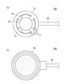
- FIG. 1 schematically shows top views of a sealed object 100 and a sealed structure 200 before and after molding.
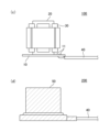
- FIG. 2 schematically shows side views of the sealed object 100 and the sealed structure 200 before and after molding.
- (a) and (c) schematically represent the sealed object 100 before molding
- (b) and (d) schematically represent the sealed structure 200 after molding.
- the sealing structure 200 in this embodiment includes a substrate 10 on which an electronic component 11 is mounted, a stator core 20 fixed on one surface of the substrate 10 and having a plurality of slots 21 formed in the circumferential direction, and a stator core 20 having a plurality of slots 21 formed in the circumferential direction.
- the sealed body 100 sealed with the molding resin composition of the present embodiment is fixed on the substrate 10 on which the electronic component 11 is mounted and on one surface of the substrate 10.
- the stator core 20 includes a stator core 20 having a plurality of slots 21 formed in the circumferential direction, and a plurality of coils 30 accommodated in the slots 21.
- the board 10 is, for example, a board on which electronic components 11 are mounted on one or both of one surface and the other surface opposite to the one surface.
- the substrate 10 has, for example, a flat plate shape.
- the substrate 10 may have a solder resist layer on one surface on which the electronic component 11 is mounted, for example.
- the solder resist layer can be formed using a solder resist forming resin composition commonly used in the field of semiconductor devices.
- a solder resist layer can be provided on one side and the other side of the substrate 10, for example.
- the solder resist layer provided on one surface or both of the one surface and the other surface of the substrate 10 is formed of, for example, a resin composition containing a silicone compound. Thereby, a solder resist layer with excellent surface smoothness can be realized.
- the electronic component 11 is mounted, for example, on one surface and the other surface of the substrate 10, as shown in FIG. 1(a). On the other hand, the electronic component 11 may be provided only on one surface of the substrate 10 and may not be provided on the other surface of the substrate 10.
- Examples of the electronic components 11 include light emitting elements such as LED chips, biometric meters that detect biopotentials such as electroencephalograms and myoelectric potentials, and bioactivity such as blood pressure and pulse, pressure, temperature, position, humidity, light, sound, etc. Examples include general measuring meters that detect environmental information such as acceleration, elements such as portable power supplies such as capacitors, acoustic modules, and communication modules, and wiring that connects the above elements.
- a lead wire 40 is connected to the substrate 10 and the electronic component 11. Since the lead wire 40 is connected to the substrate 10 and the electronic component 11 before being sealed with the molding resin composition of this embodiment, the lead wire 40, the substrate 10 and the electronic component The connection portion with the component 11 can be sealed all at once, and as a result, the waterproofness of the sealed structure 200 of this embodiment can be improved.
- the stator core 20 is provided with a plurality of slots 21 formed in the circumferential direction when viewed from the axial end.
- four slots 21 are provided.
- the stator core 20 is fixed on one surface of the substrate 10 on which the electronic component 11 is mounted, as shown in FIG. 2(c).
- the stator core 20 may be provided by laminating a plurality of electromagnetic steel plates in the axial direction and tightly fixing them, or may be provided by molding a resin composition.
- the coil 30 has a U-shape, for example, a rectangular wire, and is wound so as to be accommodated in two spaced apart slots 21.
- Coil 30 has a first coil end and a second coil end. The first coil end protrudes to one side of the stator core 20 in the axial direction. The second coil end protrudes toward the other axial side of stator core 20. That is, the coil 30 has a pair of coil ends that respectively protrude on both sides of the stator core 20 in the axial direction.
- the sealing member 50 is fixed to the substrate 10 on which the electronic component 11 described above is mounted, and is fixed on one surface of the substrate 10 and formed in the circumferential direction.
- the stator core 20 having a plurality of slots 21 and the plurality of coils 30 housed in the slots 21 are sealed together. That is, the sealing member 50 includes the substrate 10 on which the electronic component 11 is mounted, the stator core 20 fixed on one surface of the substrate 10 and having a plurality of slots 21 formed in the circumferential direction, and the stator core 20 accommodated in the slot 21. It is provided so as to cover part or all of the object to be sealed 100 including the plurality of coils 30 .
- the material for the sealing member 50 the above-mentioned molding resin composition is used.
- the connecting portions between the lead wire 40, the substrate 10, and the electronic component 11 be sealed all at once with a sealing member 50.
- the waterproofness of the sealing structure 200 of this embodiment can be improved.
- the manufacturing method of the sealing structure of this embodiment includes a mold in a transfer molding machine that includes a substrate on which electronic components are mounted, and a stator core fixed on the substrate having a plurality of slots formed in the circumferential direction. and a plurality of coils accommodated in the slots, and a step of arranging the substrate in the mold with the molding resin composition of the present embodiment by a transfer molding method using the transfer molding machine. , a step of obtaining a sealed structure by sealing and molding the stator core and the coil.
- the step of obtaining the sealed structure is performed, for example, at a temperature of 80° C. or more and less than 180° C. and a pressure of 1 MPa or more and 15 MPa or less.
- the above step is performed at a temperature of 120° C. or more and 170° C. or less and a pressure of 3 MPa or more and 12 MPa or less.
- sealing molding be performed at a temperature equal to or lower than the Tg of the cured resin composition for molding.
- the step of obtaining the sealed structure includes: (A) A molding process using methods such as transfer molding and compression molding, (B) After the molding step, it may include a post-curing step of heating the molded body.
- a preferable aspect of this embodiment is to perform only the molding step (A) without performing the post-curing step (B).
- productivity is improved, and thermal damage due to post-curing, that is, thermal damage to the stator core, coil, and substrate to be sealed, can be suppressed, and a good sealed structure can be obtained.
- the molding resin composition is configured such that the flexural modulus (according to JIS K6911:2006) at 25°C is 0.1 GPa or more and 30 GPa or less in a cured product cured at 140°C for 2 minutes. Therefore, even if (B) is omitted, a good crosslinked structure can be obtained.
- the molding temperature in (A) is preferably at most Tg (°C) of the cured product obtained from the molding resin composition, more preferably at most (Tg-10°C). , most preferably (Tg-30°C) or lower. Further, the molding temperature is preferably 160°C or lower, more preferably 140°C or lower, and most preferably 130°C or lower. By molding at such a low temperature, thermal damage to the stator core, coil, and substrate to be sealed can be suppressed, and a good sealed structure can be obtained.
- the lower limit of the molding temperature is not particularly limited as long as the molding resin composition can be sufficiently cured. For example, it can be set to (Tg - 80°C) or higher, and can be set to 90°C or higher.
- the post-curing temperature in the case of performing the post-curing (B) above is also preferably in the same range as the molding temperature. That is, the temperature is preferably at most Tg (°C) of the cured product obtained from the molding resin composition, more preferably at most (Tg - 10°C), most preferably at most (Tg - 30°C). be. Further, the molding temperature is preferably 160°C or lower, more preferably 140°C or lower, and most preferably 130°C or lower. By post-curing at such a low temperature, thermal damage to the object to be sealed can be suppressed and a good sealed structure can be obtained. There is no particular restriction on the lower limit of the molding temperature, but it can be, for example, (Tg - 80°C) or higher, or 90°C or higher.
- the temperature of the above (A) and the above (B) is usually set to a temperature exceeding the Tg (°C) of the cured product obtained from the molding resin composition.
- the temperature range of the above-mentioned low temperature range is preferable.
- the molding resin composition is configured such that the flexural modulus at 25°C (based on JIS K6911:2006) of the cured product cured at 140°C for 2 minutes is 0.1 GPa or more and 30 GPa or less. Therefore, a good crosslinked structure can be obtained even if the temperature in (A) or (B) is lowered.
- Example 1 ⁇ Preparation of resin composition for molding>
- a molding resin composition was prepared as follows. First, the components shown in Table 1 were mixed using a mixer. Next, the obtained mixture was roll-kneaded, cooled, and pulverized to obtain a molding resin composition in the form of powder.
- Inorganic filler ⁇ Inorganic filler 1: Fused spherical silica (manufactured by Denka Co., Ltd., product name "FB-950") ⁇ Inorganic filler 2: Fused spherical silica (manufactured by Denka Co., Ltd., product name "FB-105”) ⁇ Inorganic filler 3: Alumina (manufactured by Denka Co., Ltd., product name "DAW-02")
- Coupled N-phenyl-3-aminopropyltrimethoxysilane (manufactured by Dow Corning Toray Co., Ltd., product name "CF-4083")
- Epoxy resin (Epoxy resin) ⁇ Epoxy resin 1: Orthocresol novolac type epoxy resin (manufactured by DIC, product name "EPICRON N-670")
- Curing agent 1 Biphenylene skeleton-containing phenol aralkyl resin (manufactured by Meiwa Kasei Co., Ltd., product name "MEH-7851SS”)
- Curing agent 2 Trisphenylmethane type phenol novolak resin (manufactured by Meiwa Kasei Co., Ltd., product name "MEH-7500”)
- Adhesion aid 3-amino-1,2,4-triazole
- Carbon black manufactured by Mitsubishi Chemical Corporation, product name "Carbon #5"
- a 23 mm ⁇ x 0.9 mm glass epoxy substrate (a substrate with an IC package and an aluminum electrolytic capacitor mounted on it) was molded at a mold temperature of 140°C using a low-pressure transfer molding machine (manufactured by Kotaki Seiki Co., Ltd., KTS-30).
- the resin composition was injection molded onto the substrate to a thickness of 2 cm under conditions of an injection pressure of 3 to 5 MPa and a curing time of 2 minutes to obtain a substrate sealed body without post-curing. Thereafter, the substrate sealed body was immersed in a pure water pool with a depth of 15 to 100 cm for 1000 hours. Thereafter, after air drying, continuity of the circuit wiring on the board was confirmed using a tester.
- linear expansion coefficient ⁇ 1 The linear expansion coefficient of the obtained molding resin composition was measured for each Example and each Comparative Example. Injection molding was performed using a low-pressure transfer molding machine (KTS-30 manufactured by Kotaki Seiki Co., Ltd.) under the conditions of a mold temperature of 175°C, an injection pressure of 9.8 MPa, and a curing time of 3 minutes to form a 15 mm x 4 mm x 4 mm mold. I got the item. Next, the obtained molded article was post-cured at 175° C. for 4 hours to prepare a test piece.
- KTS-30 low-pressure transfer molding machine
- test piece was measured using a thermomechanical analyzer (TMA100, manufactured by Seiko Instruments Inc.) under conditions of a measurement temperature range of 0°C to 400°C and a heating rate of 5°C/min.
- TMA100 thermomechanical analyzer
- the average linear expansion coefficient ⁇ 1 (ppm/°C) at 25-70°C was measured.
- Glass transition temperature (Tg) Glass transition temperature of the molding resin composition of each Example and each Comparative Example was measured according to JIS K 6911:2006. That is, the molding resin compositions of each Example and each Comparative Example were cured using a transfer molding machine (manufactured by Kotaki Seiki Co., Ltd., "KTS-15") at a mold temperature of 175° C. and an injection pressure of 6.9 MPa. A test piece of 80 mm x 10 mm x 4 mm was molded in 90 seconds. Then, it was post-cured at 175°C for 2 hours.
- KTS-15 transfer molding machine
- thermomechanical analyzer (TMA/SS6000, manufactured by Seiko Instruments)
- Tg glass transition temperature
- the molding resin compositions of each Example and each Comparative Example were molded using a transfer molding machine (manufactured by Kotaki Seiki Co., Ltd., "KTS-15") at a mold temperature of 175°C, an injection pressure of 6.9 MPa, and a curing time of 90. Injection molding was performed in seconds to obtain a molded product measuring 80 mm x 10 mm x 4 mm. Next, the obtained molded body was post-cured at 175° C. for 2 hours to obtain a test piece. Thermal diffusivity of the obtained test piece was measured using a laser flash method (Xenon Flash Analyzer LFA447 manufactured by NETZSCH).
- the specific gravity of the test piece used for thermal conductivity measurement was measured.
- a differential scanning calorimeter DSC8230 manufactured by Rigaku Co., Ltd. the specific heat of the test piece used for the thermal conductivity and specific gravity measurement was measured.
- the thermal conductivity (W/m ⁇ K) of the test piece in the thickness direction was calculated from the measured values of thermal diffusivity, specific gravity, and specific heat.
- room temperature storage Room temperature storage stability was measured for the molding resin compositions of each Example and each Comparative Example.
- a low-pressure transfer molding machine KTS-30 manufactured by Kotaki Seiki Co., Ltd.
- the resin composition was injected, the flow length was measured, and the spiral flow at this time was defined as S1 .
- the flow length was measured under the same conditions as above, and the spiral flow at this time was designated as S2 .
- the above S 1 and S 2 were evaluated based on the following criteria. A: S 2 ⁇ 0.8 ⁇ S 1 is satisfied. B: Satisfies S 2 ⁇ 0.8 ⁇ S 1 .
- All of the molding resin compositions of Examples could be cured at low temperatures and had excellent adhesion and waterproof properties when sealing structures such as electronic components or stators.
Landscapes
- Chemical & Material Sciences (AREA)
- Health & Medical Sciences (AREA)
- Chemical Kinetics & Catalysis (AREA)
- Medicinal Chemistry (AREA)
- Polymers & Plastics (AREA)
- Organic Chemistry (AREA)
- Epoxy Resins (AREA)
- Structures Or Materials For Encapsulating Or Coating Semiconductor Devices Or Solid State Devices (AREA)
- Compositions Of Macromolecular Compounds (AREA)
- Encapsulation Of And Coatings For Semiconductor Or Solid State Devices (AREA)
Priority Applications (2)
| Application Number | Priority Date | Filing Date | Title |
|---|---|---|---|
| JP2023552516A JP7501801B2 (ja) | 2022-03-31 | 2023-03-23 | 成形用樹脂組成物、封止構造体の製造方法および封止構造体 |
| CN202380027928.6A CN118872047A (zh) | 2022-03-31 | 2023-03-23 | 成型用树脂组合物、密封结构体的制造方法和密封结构体 |
Applications Claiming Priority (2)
| Application Number | Priority Date | Filing Date | Title |
|---|---|---|---|
| JP2022058500 | 2022-03-31 | ||
| JP2022-058500 | 2022-03-31 |
Publications (1)
| Publication Number | Publication Date |
|---|---|
| WO2023189996A1 true WO2023189996A1 (ja) | 2023-10-05 |
Family
ID=88201921
Family Applications (1)
| Application Number | Title | Priority Date | Filing Date |
|---|---|---|---|
| PCT/JP2023/011406 Ceased WO2023189996A1 (ja) | 2022-03-31 | 2023-03-23 | 成形用樹脂組成物、封止構造体の製造方法および封止構造体 |
Country Status (4)
| Country | Link |
|---|---|
| JP (1) | JP7501801B2 (https=) |
| CN (1) | CN118872047A (https=) |
| TW (1) | TW202348678A (https=) |
| WO (1) | WO2023189996A1 (https=) |
Citations (5)
| Publication number | Priority date | Publication date | Assignee | Title |
|---|---|---|---|---|
| JP2001196400A (ja) * | 2000-01-11 | 2001-07-19 | Sanyo Electric Co Ltd | 半導体装置の製造方法 |
| JP2010110198A (ja) * | 2008-09-30 | 2010-05-13 | Canon Inc | インナーロータ型ブラシレスモータ |
| JP2015000941A (ja) * | 2013-06-14 | 2015-01-05 | 日立化成株式会社 | エポキシ樹脂組成物及び電子部品装置 |
| JP2017206631A (ja) * | 2016-05-19 | 2017-11-24 | パナソニックIpマネジメント株式会社 | 封止用樹脂組成物、その硬化物、及び半導体装置 |
| JP2021015932A (ja) * | 2019-07-16 | 2021-02-12 | 住友ベークライト株式会社 | 封止樹脂組成物およびモールドコイル |
Family Cites Families (2)
| Publication number | Priority date | Publication date | Assignee | Title |
|---|---|---|---|---|
| JP7302166B2 (ja) * | 2018-12-10 | 2023-07-04 | 住友ベークライト株式会社 | ステータコア絶縁用樹脂組成物 |
| AU2020431621B2 (en) * | 2020-02-26 | 2023-07-06 | Mitsubishi Electric Corporation | Stator, Motor, Fan, Air Conditioner, and Manufacturing Method of Stator |
-
2023
- 2023-03-23 JP JP2023552516A patent/JP7501801B2/ja active Active
- 2023-03-23 WO PCT/JP2023/011406 patent/WO2023189996A1/ja not_active Ceased
- 2023-03-23 CN CN202380027928.6A patent/CN118872047A/zh active Pending
- 2023-03-27 TW TW112111513A patent/TW202348678A/zh unknown
Patent Citations (5)
| Publication number | Priority date | Publication date | Assignee | Title |
|---|---|---|---|---|
| JP2001196400A (ja) * | 2000-01-11 | 2001-07-19 | Sanyo Electric Co Ltd | 半導体装置の製造方法 |
| JP2010110198A (ja) * | 2008-09-30 | 2010-05-13 | Canon Inc | インナーロータ型ブラシレスモータ |
| JP2015000941A (ja) * | 2013-06-14 | 2015-01-05 | 日立化成株式会社 | エポキシ樹脂組成物及び電子部品装置 |
| JP2017206631A (ja) * | 2016-05-19 | 2017-11-24 | パナソニックIpマネジメント株式会社 | 封止用樹脂組成物、その硬化物、及び半導体装置 |
| JP2021015932A (ja) * | 2019-07-16 | 2021-02-12 | 住友ベークライト株式会社 | 封止樹脂組成物およびモールドコイル |
Also Published As
| Publication number | Publication date |
|---|---|
| TW202348678A (zh) | 2023-12-16 |
| CN118872047A (zh) | 2024-10-29 |
| JPWO2023189996A1 (https=) | 2023-10-05 |
| JP7501801B2 (ja) | 2024-06-18 |
Similar Documents
| Publication | Publication Date | Title |
|---|---|---|
| EP2613426B1 (en) | Fixing resin composition for use in rotor | |
| JP6469943B2 (ja) | ローター固定用樹脂組成物およびローター | |
| JP5994961B1 (ja) | 封止用樹脂組成物、車載用電子制御ユニットの製造方法、および車載用電子制御ユニット | |
| JP6766360B2 (ja) | 樹脂組成物 | |
| JP5971176B2 (ja) | ロータに用いる固定用樹脂組成物 | |
| JP2016182032A (ja) | ローター固定用樹脂組成物、ローター、および自動車 | |
| JP7501801B2 (ja) | 成形用樹脂組成物、封止構造体の製造方法および封止構造体 | |
| WO2024225223A1 (ja) | エポキシ樹脂組成物粒子、タブレット、および柱状タブレットの製造方法 | |
| JP6989044B1 (ja) | 封止構造体の製造方法およびタブレット | |
| JP7845585B2 (ja) | タブレット状のエポキシ樹脂成形材料、柱状タブレットおよび柱状タブレットの製造方法 | |
| JP6275946B2 (ja) | ローター固定用樹脂組成物およびローター | |
| JP7552931B2 (ja) | 封止用樹脂組成物および片面封止構造体の製造方法 | |
| KR102681999B1 (ko) | 봉지용 수지 조성물 | |
| JP6686457B2 (ja) | 封止用樹脂組成物および電子装置 | |
| CN107531982A (zh) | 密封用树脂组合物和电子部件装置 | |
| JP5246377B2 (ja) | ロータに用いる固定用樹脂組成物およびロータ | |
| JP2024156625A (ja) | エポキシ樹脂組成物粒子、タブレット、および柱状タブレットの製造方法 |
Legal Events
| Date | Code | Title | Description |
|---|---|---|---|
| WWE | Wipo information: entry into national phase |
Ref document number: 2023552516 Country of ref document: JP |
|
| 121 | Ep: the epo has been informed by wipo that ep was designated in this application |
Ref document number: 23780007 Country of ref document: EP Kind code of ref document: A1 |
|
| WWE | Wipo information: entry into national phase |
Ref document number: 202380027928.6 Country of ref document: CN |
|
| NENP | Non-entry into the national phase |
Ref country code: DE |
|
| 122 | Ep: pct application non-entry in european phase |
Ref document number: 23780007 Country of ref document: EP Kind code of ref document: A1 |