WO2023189868A1 - ヒータ装置 - Google Patents
ヒータ装置 Download PDFInfo
- Publication number
- WO2023189868A1 WO2023189868A1 PCT/JP2023/011052 JP2023011052W WO2023189868A1 WO 2023189868 A1 WO2023189868 A1 WO 2023189868A1 JP 2023011052 W JP2023011052 W JP 2023011052W WO 2023189868 A1 WO2023189868 A1 WO 2023189868A1
- Authority
- WO
- WIPO (PCT)
- Prior art keywords
- slits
- heat generating
- heater device
- heat
- heat insulating
- Prior art date
- Legal status (The legal status is an assumption and is not a legal conclusion. Google has not performed a legal analysis and makes no representation as to the accuracy of the status listed.)
- Ceased
Links
Images






Classifications
-
- F—MECHANICAL ENGINEERING; LIGHTING; HEATING; WEAPONS; BLASTING
- F28—HEAT EXCHANGE IN GENERAL
- F28F—DETAILS OF HEAT-EXCHANGE AND HEAT-TRANSFER APPARATUS, OF GENERAL APPLICATION
- F28F3/00—Plate-like or laminated elements; Assemblies of plate-like or laminated elements
- F28F3/08—Elements constructed for building-up into stacks, e.g. capable of being taken apart for cleaning
- F28F3/10—Arrangements for sealing the margins
-
- H—ELECTRICITY
- H05—ELECTRIC TECHNIQUES NOT OTHERWISE PROVIDED FOR
- H05B—ELECTRIC HEATING; ELECTRIC LIGHT SOURCES NOT OTHERWISE PROVIDED FOR; CIRCUIT ARRANGEMENTS FOR ELECTRIC LIGHT SOURCES, IN GENERAL
- H05B3/00—Ohmic-resistance heating
- H05B3/20—Heating elements having extended surface area substantially in a two-dimensional [2D] plane, e.g. plate-heater
- H05B3/34—Heating elements having extended surface area substantially in a two-dimensional [2D] plane, e.g. plate-heater flexible, e.g. heating nets or webs
-
- F—MECHANICAL ENGINEERING; LIGHTING; HEATING; WEAPONS; BLASTING
- F28—HEAT EXCHANGE IN GENERAL
- F28F—DETAILS OF HEAT-EXCHANGE AND HEAT-TRANSFER APPARATUS, OF GENERAL APPLICATION
- F28F2275/00—Fastening; Joining
- F28F2275/02—Fastening; Joining by using bonding materials; by embedding elements in particular materials
- F28F2275/025—Fastening; Joining by using bonding materials; by embedding elements in particular materials by using adhesives
-
- H—ELECTRICITY
- H05—ELECTRIC TECHNIQUES NOT OTHERWISE PROVIDED FOR
- H05B—ELECTRIC HEATING; ELECTRIC LIGHT SOURCES NOT OTHERWISE PROVIDED FOR; CIRCUIT ARRANGEMENTS FOR ELECTRIC LIGHT SOURCES, IN GENERAL
- H05B2203/00—Aspects relating to Ohmic resistive heating covered by group H05B3/00
- H05B2203/013—Heaters using resistive films or coatings
-
- H—ELECTRICITY
- H05—ELECTRIC TECHNIQUES NOT OTHERWISE PROVIDED FOR
- H05B—ELECTRIC HEATING; ELECTRIC LIGHT SOURCES NOT OTHERWISE PROVIDED FOR; CIRCUIT ARRANGEMENTS FOR ELECTRIC LIGHT SOURCES, IN GENERAL
- H05B2203/00—Aspects relating to Ohmic resistive heating covered by group H05B3/00
- H05B2203/02—Heaters using heating elements having a positive temperature coefficient
Definitions
- the present disclosure relates to a heater device.
- heater devices including a surface layer portion, a heat generating portion, and a heat insulating portion are known (see, for example, Patent Document 1).
- a surface layer part, a heat generating part, and a heat insulating part are laminated in this order with a curable adhesive interposed therebetween.
- the present inventors studied a structure in which a surface layer and a heat insulating part are attached to a flexible heat generating part using an adhesive. did.
- An object of the present disclosure is to provide a heater device that can suppress unintended deformation of the heater surface while ensuring followability to the external shape of an installation target.
- the heater device is a flexible heat generating part; a surface layer part that covers the surface side of the heat generating part; A heat insulating part that covers the back side of the heat generating part and blocks the heat generated by the heat generating part,
- the heat generating part, the surface layer part, and the heat insulating part are configured as a laminate in which the surface layer part, the heat generating part, and the heat insulating part are laminated in this order via an adhesive, A plurality of slits are provided in the laminate to suppress deformation due to differences in linear expansion coefficients of the heat generating part, the surface layer part, and the heat insulating part.
- the heater device of the present disclosure it is possible to suppress the occurrence of unintended deformation of the heater surface while ensuring followability to the external shape of the installation target.
- the "adhesive” is also called a pressure-sensitive adhesive.
- “Adhesives” maintain their viscosity even over time, and are clearly distinguished from curable adhesives that harden over time. Curable adhesives can be expected to suppress deformation due to differences in linear expansion coefficients due to their curing properties, but they cannot be used because they do not satisfy the heat resistance required for heater devices and there is also the problem of odor due to volatile components.
- the term “flexibility” as used herein refers to the property of an object being flexible and capable of bending.
- slit in this specification includes not only a cut or a slit that does not penetrate an object but also one that penetrates an object, such as a straight line, a curve, an L-shape, an x-shape, etc.
- the length and the like are not particularly limited.
- FIG. 2 is a schematic diagram showing a vehicle interior space in which the heater device according to the first embodiment is installed.
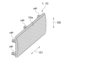
- FIG. 1 is a schematic perspective view of a heater device according to a first embodiment. It is a typical sectional view of a heater main part of a heater device concerning a 1st embodiment.
- FIG. 7 is an explanatory diagram for explaining thermal stress and the like that occur when the heat generating portion of the heater device as a first comparative example generates heat.
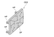
- FIG. 6 is an explanatory diagram for explaining deformation that occurs when the heat generating portion of the heater device as a first comparative example generates heat.
- 4 is a schematic plan view of the VI portion of FIG. 3.
- FIG. 7 is a sectional view taken along line VII-VII of FIG. 6.
- FIG. 3 is an explanatory diagram for explaining thermal stress and the like that occur when the heat generating portion of the heater device according to the first embodiment generates heat.
- FIG. 7 is an explanatory diagram for explaining thermal stress and the like that occur when the heat generating portion of the heater device according to the first modification of the first embodiment generates heat.
- FIG. 7 is an explanatory diagram for explaining thermal stress and the like that occur when the heat generating portion of the heater device according to the second modification of the first embodiment generates heat.
- FIG. 7 is an explanatory diagram for explaining thermal stress and the like that occur when the heat generating portion of the heater device according to the third modification of the first embodiment generates heat.
- FIG. 7 is an explanatory diagram for explaining thermal stress and the like that occur when the heat generating portion of the heater device that is a fourth modification of the first embodiment generates heat. It is an explanatory view for explaining thermal stress etc. which occur when heat is generated in the heat generating part of the heater device which is the fifth modification of the first embodiment.
- FIG. 3 is a schematic perspective view of a heater device according to a second embodiment.
- FIG. 7 is an explanatory diagram for explaining deformation that occurs when the heat generating portion of the heater device as a second comparative example generates heat.
- FIG. 7 is a schematic plan view of a heat insulating section of a heater device according to a second embodiment. It is a typical sectional view of a heater main part of a heater device concerning a 3rd embodiment. It is a typical sectional view of a heater main part of a heater device concerning a 4th embodiment.
- the heater device 1 includes a sheet-shaped heater main body 10 and a heater control section (not shown).
- the heater main body portion 10 is installed below the steering column SC that supports the steering wheel HL.
- the heater main body 10 radiates radiant heat H from the heater surface 10a toward the feet of the occupant seated on the seat S.
- the steering column SC is the installation target of the heater device 1.
- the heater control section is a control section that controls the operation of the heater main body section 10.
- the heater control section includes a microcomputer including a processor, a memory, and its peripheral circuits.
- the heater main body 10 has a substantially rectangular outer shape on the side of the heater surface 10a.
- the heater main body 10 is installed with its longitudinal direction D1 extending along the width direction of the vehicle.
- the heater main body portion 10 may be installed, for example, in a posture in which the short direction D2 extends along the width direction of the vehicle.
- the heater main body 10 is provided with a plurality of claws HP on the back side of the heater surface 10a for attachment to an installation target. By attaching this claw portion HP to the installation target side, the heater main body 10 is fixed to the installation target.
- the heater main body portion 10 includes a flexible heat generating portion 12, a surface layer portion 14, a heat insulating portion 16, and a case portion 18.
- the heat generating part 12, the heat generating part 12, and the heat insulating part 16 are arranged in order from the heater surface 10a side.
- the heat generating unit 12 is a heater that generates heat by itself and radiates radiant heat H when energized.
- the heat generating unit 12 of the present embodiment is constituted by a film heater in which a heat generating element is mounted on a thin film-like flexible substrate so as to be able to follow the external shape of the installation target.
- the surface layer portion 14 is arranged on the surface side of the heat generating portion 12 and covers the surface side of the heat generating portion 12.
- the surface layer portion 14 is located at the outermost side of the heater main body portion 10.
- the surface of the surface layer portion 14 constitutes the heater surface 10a.
- the surface layer portion 14 is made of a material having a smaller coefficient of linear expansion than the constituent material of the heat generating portion 12 .
- the surface layer portion 14 is made of a fabric material.
- the fabric material is made of, for example, resin fibers such as polyester fibers.
- the heat insulating section 16 is arranged between the heat generating section 12 and the installation target to suppress heat transfer due to heat conduction from the heat generating section 12 to the installation target.
- the heat insulating part 16 is arranged on the back side of the heat generating part 12 and covers the back side of the heat generating part 12.
- the heat insulating section 16 blocks the heat generated by the heat generating section 12.
- the heat insulating section 16 is made of a material having a smaller coefficient of linear expansion than the constituent material of the heat generating section 12 .
- the heat insulating section 16 is made of a resin material such as urethane foam.
- the heat insulating part 16 has a certain degree of flexibility so that it can follow the external shape of the installation target.
- the case part 18 holds the laminate ST of the surface layer part 14, the heat generating part 12, and the heat insulating part 16.
- the case portion 18 has a bottom portion 181 disposed on the back side of the heat insulating portion 16 .
- the above-mentioned claw portion HP is arranged on the opposite side of the heat insulating portion 16.
- the case portion 18 is made of synthetic resin or the like.
- the heat generating part 12 is not bonded to the surface layer part 14 and the heat insulating part 16, an unintended gap will be formed between the surface layer part 14, the heat generating part 12, and the heat insulating part 16 when the heater device 1 is installed. It becomes easy to be attacked. This is not preferable because it becomes a factor that reduces the ability to follow the external shape of the installation target. For example, when the heater main body 10 is placed near the passenger as in this embodiment, it may be required to follow a design including a curved surface, but the heat generating part 12 is placed in the surface layer 14 and the heat insulating part 16. If it is not bonded, it cannot be applied to design surfaces including concave shapes.
- the same reference numerals as in the heater device 1 of this embodiment are attached to the components corresponding to the heater device 1 of this embodiment in the heater device CE1 of the first comparative example.
- the heat generating part 12 when the heat generating part 12 generates heat, the heat generating part 12 tends to expand in the direction of the arrow AR1.
- the surface layer part 14 tries to expand upon receiving the heat of the heat generating part 12, but since the coefficient of linear expansion is smaller than that of the heat generating part 12, a force to cause it to contract in the direction of the arrow AR2 acts on the surface layer part 14. do.
- the heat insulating part 16 tries to expand upon receiving the heat of the heat generating part 12, but since its coefficient of linear expansion is smaller than that of the heat generating part 12, the force that causes it to contract in the direction of arrow AR3 is act.
- the heat generating part 12 is distorted due to thermal stress due to the difference in linear expansion coefficient of each member, and as shown in FIG.
- Unintended deformation DF such as the following easily occurs.
- Such unintended deformation DF is undesirable because it causes deterioration in the design of the product or installation target.
- the heater device 1 is configured as a laminate ST in which 16 layers are stacked in this order.
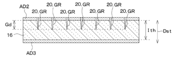
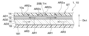
- the laminate ST is provided with a plurality of slits 20 for suppressing deformation DF caused by differences in linear expansion coefficients of the heat generating part 12, the surface layer part 14, and the heat insulating part 16.
- the heat insulating section 16 is attached to the case section 18 using an adhesive AD3.
- a plurality of slits 20 are formed in the heat insulating section 16.
- the plurality of slits 20 are formed so as to extend along one predetermined direction on the opposing surface of the heat insulating section 16 that faces the heat generating section 12 .
- the dimension in the "predetermined direction” in the plane perpendicular to the stacking direction Dst of the laminate ST is larger than the dimension in "other directions.”
- the longitudinal direction D1 of the heater main body 10 corresponds to a "predetermined direction”
- the short direction D2 of the heater main body 10 corresponds to "another direction”.
- the plurality of slits 20 extend along a direction intersecting the longitudinal direction D1, which is a "predetermined direction.” Specifically, the plurality of slits 20 extend along the short direction D2, which is the "other direction”.
- the longitudinal dimension Ls of the plurality of slits 20 is set so that a plurality of slits 20 can be provided in the longitudinal direction of the slit 20.
- the lengthwise dimension Ls of the slit 20 of this embodiment is less than half the length Lw of the heater main body 10 in the short direction D2. If the longitudinal dimension Ls of the slit 20 is too large, the shape of the heat insulating part 16 will not be stable and the shape of the heat insulating part 16 will easily collapse. It is desirable that the length is 1/3 or less of the dimension Lw in the short direction D2.
- the longitudinal dimension Ls of the plurality of slits 20 may be the same or different.
- the plurality of slits 20 are arranged in a staggered manner, with adjacent slits 20 in the lateral direction being shifted from each other in the longitudinal direction of the slits 20.
- slits 20 adjacent to each other in the lateral direction are arranged such that the longitudinal ends of the slits 20 do not coincide in the lateral direction.
- the distance between adjacent slits 20 is smaller than the longitudinal dimension Ls of the slits 20.
- the interval Li1 between the slits 20 adjacent to each other in the longitudinal direction of the slits 20 is smaller than the dimension Ls of the slits 20 in the longitudinal direction.
- the interval Li2 between the slits 20 adjacent to each other in the transverse direction of the slits 20 is smaller than the dimension Ls of the slits 20 in the longitudinal direction.
- one of the intervals Li1 between the slits 20 adjacent to each other in the longitudinal direction of the slits 20 and the interval Li2 between the slits 20 adjacent to each other in the lateral direction of the slits 20 is equal to or larger than the longitudinal dimension Ls of the slits 20. It may be.
- the plurality of slits 20 are configured not as through holes TH but as bottomed grooves GR.
- This bottomed groove GR is formed in a portion of the heat insulating portion 16 that faces the heat generating portion 12 . If the groove depth Gd of the bottomed groove GR is too large, the shape of the heat insulating part 16 will not be stable and the shape of the heat insulating part 16 will easily collapse. It is desirable that the thickness Ith of the heat insulating portion 16 in the stacking direction Dst is less than half.
- the heat insulating part 16 tends to contract in the direction of the arrow AR3a due to the difference in linear expansion coefficient with the heat generating part 12, but the slit 20 is not provided.
- the body tries to displace in the direction of arrow AR3b, which is opposite to arrow AR3a. That is, the heat insulating section 16 can easily follow the expansion of the heat generating section 12 near the slit 20. In this case, thermal stress due to the difference in linear expansion coefficient between the heat generating part 12 and the heat insulating part 16 is relaxed, so that unintended deformation DF such as unevenness and wrinkles is less likely to occur on the heater surface 10a.
- the amount of deformation in the stacking direction Dst such as wrinkles that occurs on the heater surface 10a when the heat generating portion 12 generates heat is 0.3 mm or more, It has been found that this tends to affect the appearance and appearance of the heater surface 10a.
- the amount of deformation in the stacking direction Dst such as wrinkles that occurs on the heater surface 10a is 0.2 mm or less, and the appearance and appearance of the heater surface 10a are It was found that there was almost no effect on the
- the surface layer portion 14 and the heat insulating portion 16 are bonded and laminated to the flexible heat generating portion 12 using adhesives AD1 and AD2. According to such a configuration, formation of an unintended gap between the surface layer portion 14, the heat generating portion 12, and the heat insulating portion 16 is suppressed, so that it is possible to ensure followability to the external shape of the installation target. can. Even if the steering column SC to be installed includes a concave shape, the heater device 1 of this embodiment can have a shape that follows the concave shape.
- a plurality of slits 20 are provided in the laminate ST of the surface layer portion 14, heat generating portion 12, and heat insulating portion 16. According to this, by imparting elasticity to the laminate ST, the thermal stress caused by the difference in the coefficient of linear expansion of each member is alleviated in the plurality of slits 20. Deformed DF can be suppressed.
- the heater device 1 of this embodiment it is possible to suppress the occurrence of unintended deformation DF of the heater surface 10a while ensuring followability to the external shape of the installation target. Since the heater device 1 of this embodiment does not require an increase in the number of parts, improved productivity and lower costs can be expected.
- the heater device 1 of this embodiment has the following features.
- the plurality of slits 20 are composed of bottomed grooves GR formed in the heat insulating part 16. In this way, when the plurality of slits 20 are configured as bottomed grooves GR, the shape of the heat insulating portion 16 is easily maintained. This is also very effective in suppressing the occurrence of unintended deformation DF due to differences in linear expansion coefficients of each member. Furthermore, the fact that the shape of the heat insulating portion 16 is easily maintained also contributes to improved productivity. The same applies to the case where a plurality of bottomed slits 20 are provided in the heat generating part 12 and the surface layer part 14.
- the plurality of slits 20 are provided in the heat insulating section 16 of the laminate ST. According to this, the plurality of slits 20 provided in the heat insulating part 16 can suppress unintended deformation DF due to the difference in coefficient of linear expansion between the heat generating part 12 and the heat insulating part 16.
- the plurality of slits 20 are formed to extend along one predetermined direction on the opposing surface of the heat insulating section 16 that faces the heat generating section 12. According to this, the thermal stress acting in a direction intersecting one predetermined direction can be relaxed by the slit 20, so that deformation DF due to the thermal stress can be suppressed.
- the plurality of slits 20 extend along a direction intersecting the longitudinal direction D1. According to this, since the thermal stress acting in the longitudinal direction D1 can be relaxed by the slit 20, it is possible to suppress the occurrence of deformation DF of the heater surface 10a due to the thermal stress.
- At least some of the plurality of slits 20 have a longitudinal dimension Ls set so that a plurality of slits 20 can be provided in the longitudinal direction of the slit 20.
- the slit 20 is provided so as to extend from one end to the other end in the longitudinal direction D1 of the heat insulating part 16, the shape of the heat insulating part 16 will not be stable, and the shape of the heat insulating part 16 will easily collapse.
- the longitudinal dimension Ls of the slit 20 is set to a dimension that allows a plurality of slits 20 to be provided in the longitudinal direction of the slit 20, the shape of the heat insulating section 16 can be easily maintained. This is also very effective in suppressing the occurrence of deformation DF of the heater surface 10a caused by thermal stress.
- the distance between adjacent slits 20 is smaller than the longitudinal dimension Ls of the slits 20. In this way, if the distance between adjacent slits 20 is small, it becomes easier to relieve the thermal stress caused by the difference in the linear expansion coefficient of each member, thereby suppressing the generation of heater surface 10a caused by the thermal stress. be able to.
- the plurality of slits 20 are arranged such that adjacent ones in the lateral direction of the slits 20 are shifted from each other in the longitudinal direction of the slit 20. In this way, if the plurality of slits 20 are arranged in a staggered manner, the thermal stress due to the difference in the coefficient of linear expansion of each member can be easily alleviated, thereby preventing the occurrence of deformation DF of the heater surface 10a due to the thermal stress. can be suppressed.
- the plurality of slits 20 may be configured, for example, as through holes TH penetrating the front and back sides of the heat insulating section 16, as shown in FIG. 9, instead of the bottomed grooves GR.
- the heat insulating part 16 tends to contract in the direction of the arrow AR3a due to the difference in linear expansion coefficient with the heat generating part 12, but the slit 20 is not provided.
- the body tries to displace in the direction of arrow AR3b, which is opposite to arrow AR3a. That is, the heat insulating section 16 can easily follow the expansion of the heat generating section 12 near the slit 20. In this case, thermal stress due to the difference in linear expansion coefficient between the heat generating part 12 and the heat insulating part 16 is relaxed, so that unintended deformation DF such as unevenness and wrinkles is less likely to occur on the heater surface 10a.
- each of the plurality of slits 20 be configured as a bottomed groove GR.
- the plurality of slits 20 described in the first embodiment have a longitudinal dimension Ls that is less than half the dimension Lw in the short direction D2 of the heat insulating section 16, the present invention is not limited thereto.
- the longitudinal dimension Ls of the plurality of slits 20 may be larger than half the dimension Lw in the short direction D2 of the heat insulating section 16.
- only one of the plurality of slits 20 is labeled with a reference numeral.
- the present invention is not limited thereto.
- the plurality of slits 20 may extend along directions intersecting each of the long direction D1 and the short direction D2.
- the plurality of slits 20 extend along a direction inclined with respect to the longitudinal direction D1
- the longitudinal dimension Ls of the plurality of slits 20 is set so that a plurality of slits 20 can be provided in the longitudinal direction of the slit 20.
- FIG. 12 in order to avoid complication of the drawing, only one of the plurality of slits 20 is labeled with a reference numeral.
- the present invention is not limited to this, and for example, as shown in FIG. 13, the slits 20 may extend along the long direction D1. .
- the longitudinal dimension Ls of the plurality of slits 20 is set so that a plurality of slits 20 can be provided in the longitudinal direction of the slit 20.
- FIG. 13 in order to avoid complication of the drawing, only one of the plurality of slits 20 is labeled with a reference numeral.
- the heater main body 10 of this embodiment has a substantially square outer shape on the heater surface 10a side. That is, in the heater main body portion 10, the vertical dimension Lv and the horizontal dimension Lh are approximately the same.
- the heater body 10 having the shape shown in FIG. do.
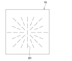
- the heater device 1 of the present embodiment has a structure in which the opposing surface of the heat insulating section 16 facing the heat generating section 12 is aligned along a plurality of predetermined directions in response to the deformed DF formed in various directions.
- a plurality of slits 20 are provided. Specifically, as shown in FIG. 16, the plurality of slits 20 are formed to extend radially around a substantially central portion of the heater surface 10a. Note that in FIG. 16, only one of the plurality of slits 20 is labeled with a reference numeral in order to avoid complicating the drawing.
- the heater device 1 of this embodiment can obtain the same effects as the first embodiment from the same configuration or equivalent configuration as the first embodiment.
- the heater device 1 of this embodiment has the following features.
- the plurality of slits 20 are formed to extend along a plurality of predetermined directions on the opposing surface of the heat insulating section 16 that faces the heat generating section 12. According to this, the thermal stress acting in a direction intersecting a plurality of predetermined directions can be relaxed by the slit 20, so that deformation DF due to the thermal stress can be suppressed. For example, in the heater device 1 of this embodiment, deformation DF as shown in FIG. 15 can be suppressed.
- the plurality of slits 20 in the second embodiment are formed to extend radially around the approximate center of the heater surface 10a, but are not limited to this, and may be formed to extend in a direction different from that described above. You can leave it there.
- a plurality of slits 20A are provided not in the heat insulating part 16 but in the heat generating part 12. Since the heat generating part 12 includes a heat generating element, electric wiring, etc., unlike the heat insulating part 16, the shape is easily maintained even if the slit 20A is formed. For this reason, the slit 20A is configured not as a bottomed groove GR but as a through hole TH. Note that the dimensions, arrangement, etc. of the slit 20A are the same as those of the slit 20 described in the first embodiment, so a description thereof will be omitted.
- the heat generating part 12 when the heat generating part 12 generates heat, the heat generating part 12 tries to expand in the direction of the arrow AR1a, but the direction of the arrow AR1b opposite to the arrow AR1a is expanded in the region where the slit 20A is provided. attempts to move in the direction of .
- the expansion of the heat generating part 12 is suppressed, and the thermal stress caused by the difference in linear expansion coefficients of the heat generating part 12, the surface layer part 14, and the heat insulating part 16 is alleviated, so that unevenness, wrinkles, etc. can be formed on the heater surface 10a. This makes it difficult for deformed DF to occur.
- the heater device 1 of this embodiment can obtain the same effects as the first embodiment from the same configuration or equivalent configuration as the first embodiment.
- the heater device 1 of this embodiment has the following features.
- the plurality of slits 20A are provided in the heat generating portion 12 of the laminate ST. According to this, the plurality of slits 20A provided in the heat generating part 12 can reduce the thermal stress due to the difference in linear expansion coefficient between the heat generating part 12 and the heat insulating part 16, or the thermal stress due to the difference in the linear expansion coefficient between the heat generating part 12 and the surface layer part 14. can be alleviated. As a result, it is possible to suppress unintended deformation DF due to differences in linear expansion coefficients of each member of the laminate ST.
- the plurality of slits 20A may be configured, for example, as bottomed grooves GR instead of the through holes TH.
- the bottomed groove GR may be formed in at least one of a portion of the heat generating portion 12 facing the heat insulating portion 16 and a portion of the heat generating portion 12 facing the surface layer portion 14 .
- the plurality of slits 20A may be formed in the manners shown in the second to fifth modifications of the first embodiment.
- the slit 20B is provided for the heat generating part 12, but the slit 20B is not limited to this, and for example, the slit 20 is provided not only for the heat generating part 12 but also for the heat insulating part 16. A plurality of them may be provided.
- a plurality of slits 20B are provided not in the heat insulating part 16 but in the surface layer part 14. Since the surface side of the surface layer portion 14 becomes the heater surface 10a, the slit 20B is configured not as a through hole TH but as a bottomed groove GR. This bottomed groove GR is formed in a portion of the surface layer portion 14 that faces the heat generating portion 12 . Note that the dimensions, arrangement, etc. of the slit 20B are the same as those of the slit 20 described in the first embodiment, so a description thereof will be omitted.
- the surface layer part 14 tends to contract in the direction of the arrow AR2a due to the difference in linear expansion coefficient with the heat generating part 12, but the slit 20B is provided.
- the body tries to displace in the direction of arrow AR2b, which is opposite to arrow AR2a. That is, the surface layer portion 14 easily follows the expansion of the heat generating portion 12 near the slit 20B. In this case, thermal stress due to the difference in linear expansion coefficient between the heat generating portion 12 and the surface layer portion 14 is relaxed, making it difficult for unintended deformation DF such as unevenness and wrinkles to occur on the heater surface 10a.
- the heater device 1 of this embodiment can obtain the same effects as the first embodiment from the same configuration or equivalent configuration as the first embodiment.
- the plurality of slits 20B are provided in the surface layer portion 14 of the laminate ST. According to this, thermal stress due to the difference in linear expansion coefficient between the heat generating portion 12 and the surface layer portion 14 can be alleviated by the plurality of slits 20B provided in the surface layer portion 14. As a result, it is possible to suppress unintended deformation DF due to differences in linear expansion coefficients of each member of the laminate ST.
- the slit 20B is provided in the surface layer portion 14, but the slit 20B is not limited thereto.
- a plurality of slits 20A may be provided not only in the surface layer portion 14, but also in the heat generating portion 12, or a plurality of slits 20 may be provided in the heat insulating portion 16, for example.
- the plurality of slits 20B may be formed in the manners shown in the second to fifth modifications of the first embodiment.
- the components of the heater device 1 have been specifically described, but some of the components of the heater device 1 may be different from those described above.
- the heater main body 10 may have a shape other than a rectangular shape.
- the heater main body 10 of the above-described embodiment includes the case portion 18, the case portion 18 is not an essential component and may be omitted. Further, although the heater main body 10 in the above-described embodiment is installed on the steering column SC, the heater body 10 is not limited thereto, and may be installed on, for example, an instrument panel, a glove box, the back of the backrest of the seat S, etc. Good too.
- the heater device 1 of the present disclosure is applied to a heating device that warms the interior of a vehicle, but the heater device 1 of the present disclosure is applicable to a heating device that warms an indoor space, a portable heating device, etc. It is also widely applicable.
Landscapes
- Engineering & Computer Science (AREA)
- Physics & Mathematics (AREA)
- Thermal Sciences (AREA)
- Mechanical Engineering (AREA)
- General Engineering & Computer Science (AREA)
- Surface Heating Bodies (AREA)
Priority Applications (3)
| Application Number | Priority Date | Filing Date | Title |
|---|---|---|---|
| CN202380028737.1A CN118901282A (zh) | 2022-03-30 | 2023-03-21 | 加热器装置 |
| DE112023001672.0T DE112023001672T5 (de) | 2022-03-30 | 2023-03-21 | Heizungsvorrichtung |
| US18/897,997 US20250020417A1 (en) | 2022-03-30 | 2024-09-26 | Heater device |
Applications Claiming Priority (2)
| Application Number | Priority Date | Filing Date | Title |
|---|---|---|---|
| JP2022-055510 | 2022-03-30 | ||
| JP2022055510A JP7786282B2 (ja) | 2022-03-30 | 2022-03-30 | ヒータ装置 |
Related Child Applications (1)
| Application Number | Title | Priority Date | Filing Date |
|---|---|---|---|
| US18/897,997 Continuation US20250020417A1 (en) | 2022-03-30 | 2024-09-26 | Heater device |
Publications (1)
| Publication Number | Publication Date |
|---|---|
| WO2023189868A1 true WO2023189868A1 (ja) | 2023-10-05 |
Family
ID=88201308
Family Applications (1)
| Application Number | Title | Priority Date | Filing Date |
|---|---|---|---|
| PCT/JP2023/011052 Ceased WO2023189868A1 (ja) | 2022-03-30 | 2023-03-21 | ヒータ装置 |
Country Status (5)
| Country | Link |
|---|---|
| US (1) | US20250020417A1 (https=) |
| JP (1) | JP7786282B2 (https=) |
| CN (1) | CN118901282A (https=) |
| DE (1) | DE112023001672T5 (https=) |
| WO (1) | WO2023189868A1 (https=) |
Cited By (1)
| Publication number | Priority date | Publication date | Assignee | Title |
|---|---|---|---|---|
| WO2025192290A1 (ja) * | 2024-03-11 | 2025-09-18 | 株式会社デンソー | フィルムヒータ |
Citations (6)
| Publication number | Priority date | Publication date | Assignee | Title |
|---|---|---|---|---|
| JPS4925043U (https=) * | 1972-06-01 | 1974-03-04 | ||
| JPS6288391U (https=) * | 1985-11-25 | 1987-06-05 | ||
| JPH09245945A (ja) * | 1996-03-05 | 1997-09-19 | Hitachi Home Tec Ltd | 面状採暖具 |
| JP2004103451A (ja) * | 2002-09-11 | 2004-04-02 | Kowa Dennetsu Keiki:Kk | 板状ヒーター |
| JP2005251509A (ja) * | 2004-03-03 | 2005-09-15 | Susumu Kiyokawa | 面状ヒーター |
| JP2019150232A (ja) * | 2018-03-01 | 2019-09-12 | ロレアル | 可撓性加熱装置 |
Family Cites Families (4)
| Publication number | Priority date | Publication date | Assignee | Title |
|---|---|---|---|---|
| JPH09318090A (ja) * | 1996-05-28 | 1997-12-12 | Matsushita Electric Works Ltd | 面状採暖器具 |
| JP2009110786A (ja) * | 2007-10-30 | 2009-05-21 | Kurabe Ind Co Ltd | ヒータユニット及びその製造方法 |
| JP6447753B2 (ja) | 2016-01-25 | 2019-01-09 | 株式会社デンソー | ヒータ装置 |
| JP7518716B2 (ja) | 2020-09-29 | 2024-07-18 | 富士紡ホールディングス株式会社 | 保持パッド |
-
2022
- 2022-03-30 JP JP2022055510A patent/JP7786282B2/ja active Active
-
2023
- 2023-03-21 DE DE112023001672.0T patent/DE112023001672T5/de active Pending
- 2023-03-21 CN CN202380028737.1A patent/CN118901282A/zh active Pending
- 2023-03-21 WO PCT/JP2023/011052 patent/WO2023189868A1/ja not_active Ceased
-
2024
- 2024-09-26 US US18/897,997 patent/US20250020417A1/en active Pending
Patent Citations (6)
| Publication number | Priority date | Publication date | Assignee | Title |
|---|---|---|---|---|
| JPS4925043U (https=) * | 1972-06-01 | 1974-03-04 | ||
| JPS6288391U (https=) * | 1985-11-25 | 1987-06-05 | ||
| JPH09245945A (ja) * | 1996-03-05 | 1997-09-19 | Hitachi Home Tec Ltd | 面状採暖具 |
| JP2004103451A (ja) * | 2002-09-11 | 2004-04-02 | Kowa Dennetsu Keiki:Kk | 板状ヒーター |
| JP2005251509A (ja) * | 2004-03-03 | 2005-09-15 | Susumu Kiyokawa | 面状ヒーター |
| JP2019150232A (ja) * | 2018-03-01 | 2019-09-12 | ロレアル | 可撓性加熱装置 |
Cited By (1)
| Publication number | Priority date | Publication date | Assignee | Title |
|---|---|---|---|---|
| WO2025192290A1 (ja) * | 2024-03-11 | 2025-09-18 | 株式会社デンソー | フィルムヒータ |
Also Published As
| Publication number | Publication date |
|---|---|
| CN118901282A (zh) | 2024-11-05 |
| JP2023147796A (ja) | 2023-10-13 |
| JP7786282B2 (ja) | 2025-12-16 |
| US20250020417A1 (en) | 2025-01-16 |
| DE112023001672T5 (de) | 2025-02-27 |
Similar Documents
| Publication | Publication Date | Title |
|---|---|---|
| JP7674438B2 (ja) | 制振材 | |
| WO2023189868A1 (ja) | ヒータ装置 | |
| JP7020439B2 (ja) | オーゼティック構造を用いて面外変形する薄型変形パネル | |
| JP7180487B2 (ja) | 車両の吸遮音構造、及び車両の吸遮音構造の製造方法 | |
| WO2014175048A1 (ja) | ワイヤハーネス取付構造 | |
| JP7074092B2 (ja) | 自律的に面外変形する薄型変形パネル | |
| US10886038B2 (en) | Exterior member-equipped wire | |
| JP5939098B2 (ja) | ワイヤハーネス | |
| JP2016210356A (ja) | ワイヤハーネス付き防音材 | |
| KR20180061785A (ko) | 차량용 히트 프로텍터 | |
| JP6998828B2 (ja) | 複合材料構造体 | |
| WO2022079999A1 (ja) | 電子部品およびその製造方法 | |
| JP7416181B2 (ja) | 配線部材 | |
| JP2010221919A (ja) | 車両天井構造 | |
| WO2016133018A1 (ja) | ワイヤーハーネス | |
| JP7014624B2 (ja) | パネル部材 | |
| KR102404248B1 (ko) | 다자유도 온도 조절 플렉시블 댐퍼 및 이를 포함하는 다자유도 플랫폼 시스템 | |
| KR20210035932A (ko) | Pct 필름을 절연 피복층으로 하는 ffc 및 그의 제조방법 | |
| JP6313550B2 (ja) | ワイヤハーネス保護構造 | |
| JP7010716B2 (ja) | パネル部材 | |
| JP6481035B2 (ja) | アクチュエータ装置およびその製造方法 | |
| KR100750862B1 (ko) | 건축용 복합 단열재 | |
| JP7302452B2 (ja) | 車体構造 | |
| JP5626904B2 (ja) | 車両用天井材 | |
| JP5248263B2 (ja) | 建物構造体及び建物ユニット |
Legal Events
| Date | Code | Title | Description |
|---|---|---|---|
| 121 | Ep: the epo has been informed by wipo that ep was designated in this application |
Ref document number: 23779882 Country of ref document: EP Kind code of ref document: A1 |
|
| WWE | Wipo information: entry into national phase |
Ref document number: 202380028737.1 Country of ref document: CN |
|
| WWE | Wipo information: entry into national phase |
Ref document number: 112023001672 Country of ref document: DE |
|
| WWP | Wipo information: published in national office |
Ref document number: 112023001672 Country of ref document: DE |
|
| 122 | Ep: pct application non-entry in european phase |
Ref document number: 23779882 Country of ref document: EP Kind code of ref document: A1 |