WO2023181547A1 - サマリウム-鉄-窒素系磁石粉末およびサマリウム-鉄-窒素系磁石 - Google Patents
サマリウム-鉄-窒素系磁石粉末およびサマリウム-鉄-窒素系磁石 Download PDFInfo
- Publication number
- WO2023181547A1 WO2023181547A1 PCT/JP2022/047146 JP2022047146W WO2023181547A1 WO 2023181547 A1 WO2023181547 A1 WO 2023181547A1 JP 2022047146 W JP2022047146 W JP 2022047146W WO 2023181547 A1 WO2023181547 A1 WO 2023181547A1
- Authority
- WO
- WIPO (PCT)
- Prior art keywords
- iron
- samarium
- nitrogen
- powder
- magnet powder
- Prior art date
- Legal status (The legal status is an assumption and is not a legal conclusion. Google has not performed a legal analysis and makes no representation as to the accuracy of the status listed.)
- Ceased
Links
Images




Classifications
-
- H—ELECTRICITY
- H01—ELECTRIC ELEMENTS
- H01F—MAGNETS; INDUCTANCES; TRANSFORMERS; SELECTION OF MATERIALS FOR THEIR MAGNETIC PROPERTIES
- H01F1/00—Magnets or magnetic bodies characterised by the magnetic materials therefor; Selection of materials for their magnetic properties
- H01F1/01—Magnets or magnetic bodies characterised by the magnetic materials therefor; Selection of materials for their magnetic properties of inorganic materials
- H01F1/03—Magnets or magnetic bodies characterised by the magnetic materials therefor; Selection of materials for their magnetic properties of inorganic materials characterised by their coercivity
- H01F1/032—Magnets or magnetic bodies characterised by the magnetic materials therefor; Selection of materials for their magnetic properties of inorganic materials characterised by their coercivity of hard-magnetic materials
- H01F1/04—Magnets or magnetic bodies characterised by the magnetic materials therefor; Selection of materials for their magnetic properties of inorganic materials characterised by their coercivity of hard-magnetic materials metals or alloys
- H01F1/047—Alloys characterised by their composition
- H01F1/053—Alloys characterised by their composition containing rare earth metals
- H01F1/055—Alloys characterised by their composition containing rare earth metals and magnetic transition metals, e.g. SmCo5
- H01F1/059—Alloys characterised by their composition containing rare earth metals and magnetic transition metals, e.g. SmCo5 and Va elements, e.g. Sm2Fe17N2
-
- B—PERFORMING OPERATIONS; TRANSPORTING
- B22—CASTING; POWDER METALLURGY
- B22F—WORKING METALLIC POWDER; MANUFACTURE OF ARTICLES FROM METALLIC POWDER; MAKING METALLIC POWDER; APPARATUS OR DEVICES SPECIALLY ADAPTED FOR METALLIC POWDER
- B22F1/00—Metallic powder; Treatment of metallic powder, e.g. to facilitate working or to improve properties
- B22F1/05—Metallic powder characterised by the size or surface area of the particles
-
- B—PERFORMING OPERATIONS; TRANSPORTING
- B22—CASTING; POWDER METALLURGY
- B22F—WORKING METALLIC POWDER; MANUFACTURE OF ARTICLES FROM METALLIC POWDER; MAKING METALLIC POWDER; APPARATUS OR DEVICES SPECIALLY ADAPTED FOR METALLIC POWDER
- B22F1/00—Metallic powder; Treatment of metallic powder, e.g. to facilitate working or to improve properties
- B22F1/14—Treatment of metallic powder
- B22F1/142—Thermal or thermo-mechanical treatment
-
- B—PERFORMING OPERATIONS; TRANSPORTING
- B22—CASTING; POWDER METALLURGY
- B22F—WORKING METALLIC POWDER; MANUFACTURE OF ARTICLES FROM METALLIC POWDER; MAKING METALLIC POWDER; APPARATUS OR DEVICES SPECIALLY ADAPTED FOR METALLIC POWDER
- B22F1/00—Metallic powder; Treatment of metallic powder, e.g. to facilitate working or to improve properties
- B22F1/17—Metallic particles coated with metal
-
- B—PERFORMING OPERATIONS; TRANSPORTING
- B22—CASTING; POWDER METALLURGY
- B22F—WORKING METALLIC POWDER; MANUFACTURE OF ARTICLES FROM METALLIC POWDER; MAKING METALLIC POWDER; APPARATUS OR DEVICES SPECIALLY ADAPTED FOR METALLIC POWDER
- B22F9/00—Making metallic powder or suspensions thereof
- B22F9/02—Making metallic powder or suspensions thereof using physical processes
- B22F9/023—Hydrogen absorption
-
- B—PERFORMING OPERATIONS; TRANSPORTING
- B22—CASTING; POWDER METALLURGY
- B22F—WORKING METALLIC POWDER; MANUFACTURE OF ARTICLES FROM METALLIC POWDER; MAKING METALLIC POWDER; APPARATUS OR DEVICES SPECIALLY ADAPTED FOR METALLIC POWDER
- B22F9/00—Making metallic powder or suspensions thereof
- B22F9/16—Making metallic powder or suspensions thereof using chemical processes
- B22F9/18—Making metallic powder or suspensions thereof using chemical processes with reduction of metal compounds
- B22F9/20—Making metallic powder or suspensions thereof using chemical processes with reduction of metal compounds starting from solid metal compounds
- B22F9/22—Making metallic powder or suspensions thereof using chemical processes with reduction of metal compounds starting from solid metal compounds using gaseous reductors
-
- C—CHEMISTRY; METALLURGY
- C22—METALLURGY; FERROUS OR NON-FERROUS ALLOYS; TREATMENT OF ALLOYS OR NON-FERROUS METALS
- C22C—ALLOYS
- C22C33/00—Making ferrous alloys
- C22C33/02—Making ferrous alloys by powder metallurgy
- C22C33/0257—Making ferrous alloys by powder metallurgy characterised by the range of the alloying elements
- C22C33/0278—Making ferrous alloys by powder metallurgy characterised by the range of the alloying elements with at least one alloying element having a minimum content above 5%
-
- C—CHEMISTRY; METALLURGY
- C22—METALLURGY; FERROUS OR NON-FERROUS ALLOYS; TREATMENT OF ALLOYS OR NON-FERROUS METALS
- C22C—ALLOYS
- C22C38/00—Ferrous alloys, e.g. steel alloys
-
- C—CHEMISTRY; METALLURGY
- C22—METALLURGY; FERROUS OR NON-FERROUS ALLOYS; TREATMENT OF ALLOYS OR NON-FERROUS METALS
- C22C—ALLOYS
- C22C38/00—Ferrous alloys, e.g. steel alloys
- C22C38/001—Ferrous alloys, e.g. steel alloys containing N
-
- C—CHEMISTRY; METALLURGY
- C22—METALLURGY; FERROUS OR NON-FERROUS ALLOYS; TREATMENT OF ALLOYS OR NON-FERROUS METALS
- C22C—ALLOYS
- C22C38/00—Ferrous alloys, e.g. steel alloys
- C22C38/002—Ferrous alloys, e.g. steel alloys containing In, Mg, or other elements not provided for in one single group C22C38/001 - C22C38/60
-
- C—CHEMISTRY; METALLURGY
- C22—METALLURGY; FERROUS OR NON-FERROUS ALLOYS; TREATMENT OF ALLOYS OR NON-FERROUS METALS
- C22C—ALLOYS
- C22C38/00—Ferrous alloys, e.g. steel alloys
- C22C38/005—Ferrous alloys, e.g. steel alloys containing rare earths, i.e. Sc, Y, Lanthanides
-
- C—CHEMISTRY; METALLURGY
- C22—METALLURGY; FERROUS OR NON-FERROUS ALLOYS; TREATMENT OF ALLOYS OR NON-FERROUS METALS
- C22C—ALLOYS
- C22C38/00—Ferrous alloys, e.g. steel alloys
- C22C38/12—Ferrous alloys, e.g. steel alloys containing tungsten, tantalum, molybdenum, vanadium, or niobium
-
- H—ELECTRICITY
- H01—ELECTRIC ELEMENTS
- H01F—MAGNETS; INDUCTANCES; TRANSFORMERS; SELECTION OF MATERIALS FOR THEIR MAGNETIC PROPERTIES
- H01F1/00—Magnets or magnetic bodies characterised by the magnetic materials therefor; Selection of materials for their magnetic properties
- H01F1/01—Magnets or magnetic bodies characterised by the magnetic materials therefor; Selection of materials for their magnetic properties of inorganic materials
- H01F1/03—Magnets or magnetic bodies characterised by the magnetic materials therefor; Selection of materials for their magnetic properties of inorganic materials characterised by their coercivity
- H01F1/032—Magnets or magnetic bodies characterised by the magnetic materials therefor; Selection of materials for their magnetic properties of inorganic materials characterised by their coercivity of hard-magnetic materials
- H01F1/04—Magnets or magnetic bodies characterised by the magnetic materials therefor; Selection of materials for their magnetic properties of inorganic materials characterised by their coercivity of hard-magnetic materials metals or alloys
- H01F1/047—Alloys characterised by their composition
- H01F1/053—Alloys characterised by their composition containing rare earth metals
- H01F1/055—Alloys characterised by their composition containing rare earth metals and magnetic transition metals, e.g. SmCo5
- H01F1/059—Alloys characterised by their composition containing rare earth metals and magnetic transition metals, e.g. SmCo5 and Va elements, e.g. Sm2Fe17N2
- H01F1/0596—Alloys characterised by their composition containing rare earth metals and magnetic transition metals, e.g. SmCo5 and Va elements, e.g. Sm2Fe17N2 of rhombic or rhombohedral Th2Zn17 structure or hexagonal Th2Ni17 structure
-
- H—ELECTRICITY
- H01—ELECTRIC ELEMENTS
- H01F—MAGNETS; INDUCTANCES; TRANSFORMERS; SELECTION OF MATERIALS FOR THEIR MAGNETIC PROPERTIES
- H01F1/00—Magnets or magnetic bodies characterised by the magnetic materials therefor; Selection of materials for their magnetic properties
- H01F1/01—Magnets or magnetic bodies characterised by the magnetic materials therefor; Selection of materials for their magnetic properties of inorganic materials
- H01F1/03—Magnets or magnetic bodies characterised by the magnetic materials therefor; Selection of materials for their magnetic properties of inorganic materials characterised by their coercivity
- H01F1/032—Magnets or magnetic bodies characterised by the magnetic materials therefor; Selection of materials for their magnetic properties of inorganic materials characterised by their coercivity of hard-magnetic materials
- H01F1/04—Magnets or magnetic bodies characterised by the magnetic materials therefor; Selection of materials for their magnetic properties of inorganic materials characterised by their coercivity of hard-magnetic materials metals or alloys
- H01F1/06—Magnets or magnetic bodies characterised by the magnetic materials therefor; Selection of materials for their magnetic properties of inorganic materials characterised by their coercivity of hard-magnetic materials metals or alloys in the form of particles, e.g. powder
-
- B—PERFORMING OPERATIONS; TRANSPORTING
- B22—CASTING; POWDER METALLURGY
- B22F—WORKING METALLIC POWDER; MANUFACTURE OF ARTICLES FROM METALLIC POWDER; MAKING METALLIC POWDER; APPARATUS OR DEVICES SPECIALLY ADAPTED FOR METALLIC POWDER
- B22F1/00—Metallic powder; Treatment of metallic powder, e.g. to facilitate working or to improve properties
- B22F1/14—Treatment of metallic powder
- B22F1/145—Chemical treatment, e.g. passivation or decarburisation
-
- B—PERFORMING OPERATIONS; TRANSPORTING
- B22—CASTING; POWDER METALLURGY
- B22F—WORKING METALLIC POWDER; MANUFACTURE OF ARTICLES FROM METALLIC POWDER; MAKING METALLIC POWDER; APPARATUS OR DEVICES SPECIALLY ADAPTED FOR METALLIC POWDER
- B22F2201/00—Treatment under specific atmosphere
- B22F2201/01—Reducing atmosphere
- B22F2201/013—Hydrogen
-
- B—PERFORMING OPERATIONS; TRANSPORTING
- B22—CASTING; POWDER METALLURGY
- B22F—WORKING METALLIC POWDER; MANUFACTURE OF ARTICLES FROM METALLIC POWDER; MAKING METALLIC POWDER; APPARATUS OR DEVICES SPECIALLY ADAPTED FOR METALLIC POWDER
- B22F2201/00—Treatment under specific atmosphere
- B22F2201/01—Reducing atmosphere
- B22F2201/016—NH3
-
- B—PERFORMING OPERATIONS; TRANSPORTING
- B22—CASTING; POWDER METALLURGY
- B22F—WORKING METALLIC POWDER; MANUFACTURE OF ARTICLES FROM METALLIC POWDER; MAKING METALLIC POWDER; APPARATUS OR DEVICES SPECIALLY ADAPTED FOR METALLIC POWDER
- B22F2301/00—Metallic composition of the powder or its coating
- B22F2301/35—Iron
- B22F2301/355—Rare Earth - Fe intermetallic alloys
-
- B—PERFORMING OPERATIONS; TRANSPORTING
- B22—CASTING; POWDER METALLURGY
- B22F—WORKING METALLIC POWDER; MANUFACTURE OF ARTICLES FROM METALLIC POWDER; MAKING METALLIC POWDER; APPARATUS OR DEVICES SPECIALLY ADAPTED FOR METALLIC POWDER
- B22F2304/00—Physical aspects of the powder
- B22F2304/10—Micron size particles, i.e. above 1 micrometer up to 500 micrometer
-
- B—PERFORMING OPERATIONS; TRANSPORTING
- B22—CASTING; POWDER METALLURGY
- B22F—WORKING METALLIC POWDER; MANUFACTURE OF ARTICLES FROM METALLIC POWDER; MAKING METALLIC POWDER; APPARATUS OR DEVICES SPECIALLY ADAPTED FOR METALLIC POWDER
- B22F2999/00—Aspects linked to processes or compositions used in powder metallurgy
-
- B—PERFORMING OPERATIONS; TRANSPORTING
- B22—CASTING; POWDER METALLURGY
- B22F—WORKING METALLIC POWDER; MANUFACTURE OF ARTICLES FROM METALLIC POWDER; MAKING METALLIC POWDER; APPARATUS OR DEVICES SPECIALLY ADAPTED FOR METALLIC POWDER
- B22F9/00—Making metallic powder or suspensions thereof
- B22F9/16—Making metallic powder or suspensions thereof using chemical processes
- B22F9/30—Making metallic powder or suspensions thereof using chemical processes with decomposition of metal compounds, e.g. by pyrolysis
-
- C—CHEMISTRY; METALLURGY
- C22—METALLURGY; FERROUS OR NON-FERROUS ALLOYS; TREATMENT OF ALLOYS OR NON-FERROUS METALS
- C22C—ALLOYS
- C22C2200/00—Crystalline structure
-
- C—CHEMISTRY; METALLURGY
- C22—METALLURGY; FERROUS OR NON-FERROUS ALLOYS; TREATMENT OF ALLOYS OR NON-FERROUS METALS
- C22C—ALLOYS
- C22C2202/00—Physical properties
- C22C2202/02—Magnetic
Definitions
- the present invention relates to samarium-iron-nitrogen magnet powder and samarium-iron-nitrogen magnet.
- Samarium-iron-nitrogen magnets have a high Curie temperature of 477°C, small temperature changes in magnetic properties, and a high anisotropic magnetic field of 260 kOe, which is the theoretical value of coercive force. Therefore, it is expected to be a high-performance magnet.
- samarium-iron-nitrogen magnet powder has a problem in that its magnetic properties deteriorate when it is sintered at high temperatures.
- the coercive force of samarium-iron-nitrogen magnets is greatly reduced by the sintering process.
- Patent Document 1 describes adding bismuth to samarium-iron-nitrogen magnet powder. That is, it is described that the coercive force of the magnet powder can be increased by using samarium-iron-bismuth-nitrogen based magnet powder.
- the present invention was made in view of this background, and an object of the present invention is to provide a samarium-iron-nitrogen magnet powder that has both high magnetization and high coercive force. Another object of the present invention is to provide a samarium-iron-nitrogen magnet that has both high magnetization and high coercive force.
- a samarium-iron-nitrogen magnet powder Contains lanthanoids (Ln), iron (Fe), bismuth (Bi), tungsten (W), and nitrogen (N),
- the lanthanoid includes samarium (Sm),
- the ratio of bismuth to the sum of lanthanoids + iron + bismuth + tungsten ((Bi/(Ln+Fe+Bi+W)) is 1.00 at% or less
- the ratio of tungsten to the sum of lanthanoid + iron + bismuth + tungsten ((W / (Ln + Fe + Bi + W)) is 0.05 at% or more and 0.60 at% or less
- a samarium-iron-nitrogen magnet powder is provided in which the atomic ratio of tungsten to bismuth (W/Bi) is 1.0 or more and 30.0 or less.
- the present invention can provide samarium-iron-nitrogen magnet powder that has both high magnetization and high coercive force. Furthermore, the present invention can provide a samarium-iron-nitrogen magnet that has both high magnetization and high coercive force.
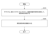
- FIG. 1 is a flow diagram schematically showing an example of a method for manufacturing samarium-iron-nitrogen magnet powder according to an embodiment of the present invention.
- 1 is a flow diagram schematically showing an example of a method for manufacturing a samarium-iron-bismuth-tungsten-nitrogen based sintered magnet using samarium-iron-nitrogen based magnet powder according to an embodiment of the present invention.
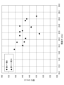
- FIG. 2 is a flow diagram schematically showing an example of a method for manufacturing a samarium-iron-bismuth-tungsten-nitrogen non-sintered magnet using samarium-iron-nitrogen magnet powder according to an embodiment of the present invention. It is a graph showing the relationship between coercive force and magnetization obtained in each example.
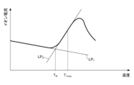
- FIG. 3 is a diagram schematically showing a graph obtained when measuring nitrogen release temperature.
- FIG. 2 is a diagram schematically showing a graph obtained during measurement of decomposition temperature. It is a graph showing the rate of change ⁇ Pa (%) of the lattice constant in the a-axis direction and the rate of change ⁇ Pc (%) of the lattice constant in the c-axis direction for each magnet powder.
- the inventors of the present application have been conducting intensive research and development on samarium-iron-nitrogen magnet powder that has both high magnetization and high coercive force.
- the present inventors found that when samarium-iron-bismuth-tungsten-nitrogen magnet powder was obtained by co-adding a predetermined amount of bismuth and tungsten to samarium-iron-nitrogen magnet powder, the magnetization of the magnet powder It has been discovered that the coercive force can be significantly increased, leading to the present invention.
- samarium-iron-nitrogen magnet powder Contains lanthanoids (Ln), iron (Fe), bismuth (Bi), tungsten (W), and nitrogen (N),
- the lanthanoid includes samarium (Sm)
- the ratio of bismuth to the sum of lanthanoids + iron + bismuth + tungsten ((Bi/(Ln+Fe+Bi+W)) is 1.00 at% or less
- the ratio of tungsten to the sum of lanthanoid + iron + bismuth + tungsten (W / (Ln + Fe + Bi + W)) is 0.05 at% or more and 0.60 at% or less
- a samarium-iron-nitrogen magnet powder is provided in which the atomic ratio of tungsten to bismuth (W/Bi) is 1.0 or more and 30.0 or less.
- the samarium-iron-bismuth-tungsten-nitrogen magnet powder according to an embodiment of the present invention is also referred to as "samarium-iron-nitrogen magnet powder.”
- the ratio of bismuth to the sum of lanthanide (Ln) + iron + bismuth + tungsten is 1.00 at% or less.
- the ratio of tungsten to the sum of lanthanoids + iron + bismuth + tungsten is Tungsten is added in an amount of 0.05 at % or more and 0.60 at % or less.
- the ratio of tungsten to bismuth (W/Bi) is 1.0 or more and 30.0 or less.
- a magnet powder with high magnetization and high coercive force is obtained.
- the reason why magnet powder having high magnetization and high coercive force can be obtained by co-adding bismuth and tungsten has not yet been fully elucidated.
- the lattice constant Pa in the a-axis direction and the lattice in the c-axis direction are higher than the basic samarium-iron-nitrogen magnet powder. It is recognized that the constant Pc increases in both cases.
- samarium-iron-nitrogen magnet powder according to an embodiment of the present invention, (Bi/(Ln+Fe+Bi+W)) is preferably 0.1 at% or less, more preferably 0.05 at% or less.
- W/(Ln+Fe+Bi+W) is preferably 0.41 at% or less.
- the atomic ratio W/Bi is preferably 20.5 or less.
- a samarium-iron-nitrogen magnet powder according to an embodiment of the present invention contains lanthanoids.
- Lanthanoids may include only samarium, but also at least one additional element selected from the group consisting of lanthanum (La), cerium (Ce), erbium (Er), thulium (Tm), and ytterbium (Yb). It may have.
- the ratio of lanthanide to the sum of lanthanide + iron + bismuth + tungsten is, for example, in the range of 10.0 at% to 15.0 at%.
- the ratio of iron to the sum of lanthanide + iron + bismuth + tungsten is, for example, in the range of 85.0 at% to 90.0 at%.
- the magnetic powder of the present invention includes a large number of particles.
- the particles have a core portion, and a coating layer may be provided on at least a portion of the core portion.
- the coating layer may cover the entire core portion.
- the core of the particle contains lanthanides, iron, bismuth, tungsten, and nitrogen.
- the core portion of the particle usually has a Th 2 Zn 17 crystal structure.
- the core portion of the particle may have a lanthanide-iron-nitrogen compound phase, for example, a Ln 2 Fe 17 N 3 phase.
- a Ln 2 Fe 17 N 3 phase may be replaced with Bi and/or W.
- at least a portion of Fe in the Ln 2 Fe 17 N 3 phase may be replaced with Bi and/or W.
- the covering layer contains lanthanoids and/or iron, but has a crystal structure different from that of the core portion.
- the covering layer may contain more lanthanide than the core part. That is, the atomic ratio of lanthanide to iron (Ln/Fe) in the coating layer may be larger than the atomic ratio of lanthanide to iron (Ln/Fe) in the core portion.
- the average particle diameter of the particles is not particularly limited, but may be, for example, less than 1.5 ⁇ m. In this case, the coercive force of the magnet powder of the present invention can be further increased.
- the number of particles having an aspect ratio of 2.0 or more is 10% or less, preferably 8% or less.
- the coercive force of the magnet powder of the present invention can be further increased.
- the magnetic powder of the present invention is characterized by a high decomposition temperature.
- the nitrogen release temperature of the magnet powder of the present invention is 610° C. or higher.
- the coercive force of the magnet powder of the present invention before heat treatment is, for example, 17 kOe or more.
- the magnetization of the magnet powder of the present invention is, for example, 140 emu/g or more. Therefore, the magnet powder of the present invention can be used as a magnet powder that has both high magnetization and high coercive force. Note that in this application, magnetization means the value of magnetization when a magnetic field of 90 kOe is applied.
- the magnet powder of the present invention having the above-mentioned characteristics may be used in the production of high-performance samarium-iron-nitrogen magnets.
- a samarium-iron-nitrogen magnet (hereinafter also simply referred to as "the magnet of the present invention") according to an embodiment of the present invention contains the magnet powder of the present invention.
- the magnet of the present invention may be a samarium-iron-nitrogen sintered magnet or a samarium-iron-nitrogen bonded magnet.
- the rare earth magnet according to the present embodiment may have a metal phase other than the Sm-Fe-N magnet powder.
- a metal phase may be, for example, a Fe phase.
- the rare earth magnet according to the present embodiment contains at least one of the following elements, such as C, Al, Si, P, Ti, Cr, Mn, Co, Cu, Zn, Y, Zr, and Sn. It may further contain one type of element.
- the content of elements other than Sm, Fe, and N is preferably 10% by mass or less, more preferably 5% by mass or less.
- lanthanoid contains another lanthanide element (at least one of La, Ce, Er, Tm, and Yb) in addition to samarium. .
- FIG. 1 schematically shows an example of the flow of the first method.
- the first method is A step of preparing a precursor powder (S110); A step of reducing and diffusing the precursor powder in an inert gas atmosphere to prepare a samarium-iron-bismuth-tungsten alloy powder (S120); nitriding the samarium-iron-bismuth-tungsten-based alloy powder to prepare samarium-iron-bismuth-tungsten-nitrogen alloy powder (S130); a step of cleaning the samarium-iron-bismuth-tungsten-nitrogen alloy powder (S140); has.
- Step S110 First, a precursor powder is produced.
- the precursor powder may be, for example, a samarium-iron-bismuth-tungsten-based oxide powder or a samarium-iron-bismuth-tungsten-based hydroxide powder.
- samarium-iron-bismuth-tungsten-based oxide powder and samarium-iron-bismuth-tungsten-based hydroxide powder are also collectively referred to as samarium-iron-bismuth-tungsten-based (hydr)oxide powder.
- the samarium-iron-bismuth-tungsten (hydr)oxide powder can be prepared by a spray pyrolysis method.
- a solution containing samarium salt, iron salt, bismuth salt, and tungsten salt is prepared.
- the composition of the samarium-iron-nitrogen magnet powder can be controlled to a desired value by adjusting the amounts of samarium salt, iron salt, bismuth salt, and tungsten salt added.
- Water can be used as the solvent contained in the solution, but organic solvents such as ethanol may also be used.
- the counter ions in samarium salts, iron salts, bismuth salts, and tungsten salts may be inorganic ions such as chloride ions, sulfate ions, or nitrate ions.
- the counterion may be an organic ion such as an alkoxide.
- the prepared solution is supplied into the heated reaction tube, and the solution is thermally decomposed.
- a sprayer such as an ultrasonic type or a two-fluid nozzle type may be used.
- fine droplets are formed from the solution, and these droplets are introduced into the reaction tube together with a carrier gas.
- the supplied solution or droplets are thermally decomposed within the reaction tube.
- the temperature inside the reaction tube is, for example, in the range of 400°C to 1000°C.
- the resulting precursor powder may then be handled in a non-oxidizing atmosphere, such as a glove box, until the samarium-iron-nitrogen magnet powder is produced.
- a non-oxidizing atmosphere such as a glove box
- the oxygen concentration is preferably 1 ppm or less.
- the obtained precursor powder is preferably pre-reduced in a reducing atmosphere. This makes it possible to reduce the amount of calcium used in the subsequent reduction and diffusion step (step S120), and to suppress the generation of coarse samarium-iron-bismuth-tungsten alloy particles.
- Pre-reduction of the precursor powder may be carried out, for example, by heating the precursor powder to 400° C. or higher in a hydrogen atmosphere.
- the treatment temperature is preferably in the range of 500°C to 800°C.
- samarium-iron-bismuth-tungsten alloy particles with uniform particle sizes can be obtained in the subsequent step.
- Step S120 the precursor powder is subjected to a reduction diffusion treatment in an inert gas atmosphere to form a samarium-iron-bismuth-tungsten alloy powder (hereinafter simply referred to as "alloy powder I").
- Examples of methods for reducing and diffusing the precursor powder include mixing the precursor powder with calcium (Ca) or calcium hydride (CaH 2 ) and then heating the mixture to a temperature higher than the melting point of Ca (approximately 850° C.). can be mentioned.
- alloy powder I samarium reduced by calcium diffuses in the calcium melt and reacts with iron, bismuth, and tungsten, thereby forming alloy powder I.
- the average particle diameter of the particles contained in alloy powder I is preferably 3.0 ⁇ m or less. When the average particle diameter is 3.0 ⁇ m or less, the coercive force of the finally obtained magnet powder becomes even higher.
- alloy powder I containing particles with uniform particle sizes it is preferable to subject the precursor powder to a reduction and diffusion treatment at 850° C. to 1050° C. for about 1 minute to 2 hours in an inert gas atmosphere.
- Each particle of the alloy powder I undergoes crystallization as reduction and diffusion progresses, and for example, a core portion having a Th 2 Zn 17 structure is formed. At this time, a coating layer is formed on at least a portion of the surface of the core portion.
- alloy powder II samarium-iron-bismuth-tungsten-nitrogen alloy powder
- Examples of the method for nitriding the alloy powder I include a method of heat treating the alloy powder I at 300° C. to 500° C. in an atmosphere of ammonia, a mixed gas of ammonia and hydrogen, nitrogen, or a mixed gas of nitrogen and hydrogen. .
- alloy powder I When ammonia is used, alloy powder I can be nitrided in a short time. However, the nitrogen content in alloy powder II may be higher than the optimum value. In this case, it is preferable to anneal the alloy powder II in hydrogen after the nitriding treatment. This allows excess nitrogen to be discharged from the crystal lattice.
- composition of the particles contained in alloy powder II is preferably Sm 2 Fe 17 N 3 .
- alloy powder I is heat treated at 350° C. to 450° C. for 10 minutes to 2 hours in an ammonia-hydrogen mixed atmosphere, and then annealed at 350° C. to 450° C. for 30 minutes to 2 hours in a hydrogen atmosphere. Thereby, the nitrogen content in alloy powder II can be optimized.
- Step S140 Next, the alloy powder II formed in step S130 is cleaned.
- Alloy powder II formed in step S130 contains a calcium compound. A cleaning process is performed to remove such calcium compounds.
- the cleaning process is performed using a cleaning liquid such as water and/or alcohol, for example.
- a cleaning liquid such as water and/or alcohol, for example.
- most of the calcium compounds contained in alloy powder II can be removed by repeating the operations of adding water to alloy powder II, followed by stirring and decantation.
- the cleaning step may be performed before the nitriding treatment.
- step S150 may be performed on the samarium-iron-bismuth-tungsten-nitrogen magnet powder (hereinafter simply referred to as "manufactured powder") obtained in step S140.
- Step S150 The manufactured powder obtained in step S140 is preferably subjected to vacuum drying treatment.
- the drying temperature is not particularly limited, but is preferably in the range of room temperature to 100°C. By setting the drying temperature to 100° C. or lower, oxidation of the manufactured powder can be suppressed.
- the manufactured powder may be subjected to dehydrogenation treatment.
- the dehydrogenation treatment can remove hydrogen that has entered between crystal lattices during the cleaning treatment.
- the method of dehydrogenation treatment is not particularly limited.
- the dehydrogenation treatment may be performed by heating the produced powder under vacuum or an inert gas atmosphere.
- the dehydrogenation treatment may be performed by heat-treating the manufactured powder at 150° C. to 450° C. for 1 hour in an argon atmosphere.
- the manufactured powder may be subsequently crushed. This improves the residual magnetization and maximum energy product of the produced powder.
- disintegration means separating one or more particles from a plurality of particles that are aggregated together.
- grinding means dividing one particle into multiple smaller pieces.
- jet mills dry and wet ball mills, vibration mills, media stirring mills, etc.
- media stirring mills etc.
- the crushing process does not necessarily need to be carried out at this stage.
- the crushing step may be performed on the alloy powder I obtained in step S120.
- the second method will be explained using an example in which only samarium is included as lanthanoid (Ln).
- the lanthanoid (Ln) contains another lanthanide element (at least one of La, Ce, Er, Tm, and Yb) in addition to samarium. .
- FIG. 2 schematically shows an example of the flow of the second method.
- the second method is a step of molding samarium-iron-bismuth-tungsten-nitrogen magnet powder to form a compact (step S210); a step of sintering the molded body (step S220); has.
- Step S210 First, samarium-iron-bismuth-tungsten-nitrogen magnet powder having the characteristics described above is prepared. Further, this magnet powder is molded to form a molded body.
- the molding method is not particularly limited, and a general magnet powder molding method may be used.
- the pressure applied during molding is, for example, in the range of 10 MPa to 3000 MPa.
- the magnet powder may be molded while a magnetic field is applied to the magnet powder.
- the magnet powder contained in the compact is oriented in a specific direction, an anisotropic magnet with high magnetic properties can be obtained.
- Step S220 Next, the molded body is sintered.
- the sintering method is not particularly limited, and general sintering methods such as a discharge plasma method and a hot press method may be used.
- the sintering temperature may be in the range of 300°C to 650°C, for example.
- step S210 and step S220 may be performed using the same device.
- a samarium-iron-bismuth-tungsten-nitrogen sintered magnet can be manufactured.
- the third method will be explained using an example in which only samarium is included as lanthanoid (Ln).
- the lanthanoid (Ln) contains another lanthanide element (at least one of La, Ce, Er, Tm, and Yb) in addition to samarium. .
- FIG. 3 schematically shows an example of the flow of the third method.
- the third method is A step of producing pellets from samarium-iron-bismuth-tungsten-nitrogen magnet powder (step S310); a step of molding the pellet (step S320); has.
- Step S310 First, pellets are produced from samarium-iron-bismuth-tungsten-nitrogen magnet powder.
- the resin used may be a thermosetting resin or a thermoplastic resin.
- thermoplastic resins are preferred. Suitable thermoplastic resins include polyamide (PA), polyphenylene sulfide (PPS), and the like.
- this mixture is heated and kneaded, and the kneaded product is made into pellets using a pelletizer or the like.
- the heating temperature may be in the range of 150°C to 330°C, for example.
- Step S320 Next, the pellets produced in step S310 are molded.
- An injection molding method may be used for the molding process.
- a molded article injection-molded into a predetermined shape can be obtained from the pellets introduced into the injection molding apparatus.
- an anisotropic bonded magnet may be obtained by molding a pellet while applying a magnetic field to a mold.
- a samarium-iron-bismuth-tungsten-nitrogen non-sintered magnet can be manufactured.
- Examples of the present invention will be described below. In the following description, Examples 1 to 9 are examples, and Examples 11 to 16 are comparative examples.
- Example 1 Magnet powder was produced by the following method.
- 10.50 ml of nitric acid was added while stirring to dissolve each salt.
- the prepared solution was formed into droplets using a spray pyrolysis device, and the droplets were thermally decomposed.
- This device has an ultrasonic atomizer and a heated reaction tube on the inlet side, and a filter is installed at the outlet of the reaction tube.
- the solution introduced into the device is transformed into fine droplets by an ultrasonic atomizer.
- This droplet is supplied into the reaction tube together with a carrier gas (atmosphere).
- the reaction tube is preheated and the droplets are thermally decomposed within the reaction tube.
- the pyrolysis products are then collected by a filter.
- the temperature of the reaction tube was 900°C.
- the obtained thermal decomposition product was pre-reduced in a hydrogen atmosphere.
- the treatment temperature was 600°C and the treatment time was 6 hours.
- a precursor powder containing samarium and lanthanum as lanthanoids was obtained.
- alloy powder A alloy powder (hereinafter referred to as "alloy powder A”) was prepared.
- alloy powder A was heated to 420°C in a mixed atmosphere of ammonia and hydrogen at a volume ratio of 1:2, maintained at this temperature for 1 hour, and subjected to nitriding treatment. carried out.
- alloy powder B was produced.
- alloy powder B was further subjected to heat treatment.
- the heat treatment was performed by annealing alloy powder B at 420° C. for 1 hour in a hydrogen atmosphere, and then annealing alloy powder B at 420° C. for 0.5 hour in an argon atmosphere.
- alloy powder B whose nitrogen content was optimized was washed five times with pure water to remove calcium compounds and the like. As a result, alloy powder C was obtained.
- the alloy powder C was subjected to a dehydrogenation treatment at 200° C. for 3 hours under vacuum.
- each step after the pre-reduction treatment was performed in a glove box in an argon atmosphere.
- Example 2 to Example 6 Magnet powder was produced in the same manner as in Example 1. However, in these Examples 2 to 6, the composition of the precursor powder was changed from that in Example 1 to produce magnet powder. Other manufacturing conditions are the same as in Example 1.
- Example 7 Magnet powder was produced in the same manner as in Example 1. However, in this Example 7, no lanthanum compound was added when preparing the precursor powder. That is, a precursor powder containing only samarium was prepared as lanthanide Ln. Note that the reduction diffusion treatment temperature was 1025°C. Other manufacturing conditions are the same as in Example 1.
- Example 8 to Example 9 Magnet powder was produced in the same manner as in Example 1. However, in these Examples 8 and 9, the composition of the precursor powder was changed from that in Example 1 to produce magnet powder. Other manufacturing conditions are the same as in Example 1.
- Example 11 to Example 13 Magnet powder was produced in the same manner as in Example 1. However, in Examples 11 to 13, the lanthanum compound, bismuth compound, and tungsten compound were not added when preparing the precursor powder. That is, in Examples 11 to 13, samarium-iron precursor powders were produced. Other manufacturing conditions are the same as in Example 1.
- Example 14 Magnet powder was produced in the same manner as in Example 1. However, in this Example 14, the lanthanum compound and the tungsten compound were not added when preparing the precursor powder. That is, in Example 14, samarium-iron-bismuth-based precursor powder was produced. Note that the reduction diffusion treatment temperature was 920°C. Other manufacturing conditions are the same as in Example 1.
- Example 15 to Example 16 Magnet powder was produced in the same manner as in Example 1. However, in these Examples 15 and 16, the amount of each component contained in the precursor powder was changed from that in Example 1 to produce magnet powder. Note that the reduction diffusion temperature was 930°C in Example 15 and 975°C in Example 16. Other manufacturing conditions are the same as in Example 1.
- each magnet powder was measured by the inert gas melting-thermal conductivity method. As a result, the nitrogen content of each magnet powder was approximately 3.3% by mass.
- composition analysis The composition of each magnet powder was analyzed by high-frequency inductively coupled plasma emission spectroscopy.
- the magnet powders according to Examples 1 to 6 are samarium-lanthanum-iron-bismuth-tungsten-nitrogen magnet powders
- the magnet powders according to Example 7 are samarium-iron-bismuth-tungsten-nitrogen magnet powders. It was confirmed that the magnet powders according to Examples 8 and 9 were samarium-lanthanum-iron-bismuth-tungsten-nitrogen magnet powders.
- the magnet powders according to Examples 11 to 13 are samarium-iron-nitrogen magnet powders
- the magnet powders according to Example 14 are samarium-iron-bismuth-nitrogen magnet powders
- examples 15 to 16 The magnet powder was confirmed to be samarium-lanthanum-iron-bismuth-tungsten-nitrogen magnet powder.
- W/Bi means the ratio (atomic ratio) of the amount of tungsten to the amount of bismuth contained in the magnet powder.
- the average particle diameter of each magnet powder was measured using a scanning electron microscope (FE-SEM).
- the aspect ratio was calculated using each of the selected particles. From the results, the proportion of particles with an aspect ratio of 2.0 or more was determined. Note that the aspect ratio was determined as the value obtained by dividing the length of the long side by the length of the short side in a rectangle that circumscribes the contour of the particle and has the minimum area.
- a sample was prepared by collecting a portion of each magnet powder, kneading it with a thermosetting epoxy resin, and thermosetting it. Further, this sample was irradiated with a focused ion beam (FIB) and etched to expose the cross section of the sample.
- FIB focused ion beam
- the cross section of the sample was observed using a scanning transmission electron microscope (STEM) and energy dispersive X-ray spectroscopy (EDS) to confirm the presence or absence of a coating layer.
- STEM scanning transmission electron microscope
- EDS energy dispersive X-ray spectroscopy
- the composition of the core portion and coating layer was analyzed by energy dispersive X-ray spectroscopy (EDS). As a result, the atomic ratio of lanthanide to iron (Ln/Fe) in the coating layer was larger than the atomic ratio of lanthanide to iron (Ln/Fe) in the core portion.
- EDS energy dispersive X-ray spectroscopy
- Coercive force and magnetization were measured using the magnet powder according to each example.
- magnet powder and thermoplastic resin were mixed and then oriented in a 20 kOe magnetic field to prepare a sample for measurement.
- VSM vibrating sample magnetometer
- magnetization means the value of magnetization obtained when a magnetic field of 90 kOe is applied.
- FIG. 4 shows the relationship between coercive force and magnetization obtained for each magnet powder.
- the nitrogen release temperature and decomposition temperature of each magnet powder were measured using a thermogravimetry device connected to a mass spectrometer.
- the measurement conditions were an argon atmosphere and a temperature increase rate of 20° C./min.
- FIG. 5 schematically shows a graph obtained when measuring the nitrogen release temperature.
- the horizontal axis is the temperature
- the vertical axis is the ion current derived from N 2 + having a mass-to-charge ratio (m/z) of 28.
- the nitrogen release temperature is determined as follows: First, as shown in FIG. 5, a first approximate straight line LP1 is drawn to correspond to the change in ion current in the temperature range of 500°C to 550°C. Next, the temperature T 1max at which the change in ion current (the positive slope of the curve in FIG. 5) is maximum is determined, and in the region of T 1max ⁇ 10°C centered on the temperature T 1max , a second approximate straight line LP 2 is determined. draw
- the nitrogen release temperature T N is determined from the intersection point on the extended line of the two approximate straight lines LP 1 and LP 2 . If the first approximation straight line deviates significantly from the actual change in the ion current, find a temperature range with relatively little variation within the temperature range of 400°C to 600°C, and select the temperature range (temperature width is 50°C). (For example, 450° C. to 500° C.) A first approximate straight line LP1 was drawn.
- the nitrogen release temperatures of the magnet powders according to Examples 1 to 9 were all 610° C. or higher.
- FIG. 6 schematically shows a graph obtained when measuring the decomposition temperature.
- the horizontal axis is temperature and the vertical axis is weight change.
- the decomposition temperature is determined as follows: First, in FIG. 6, a first approximate straight line LQ 1 is drawn to correspond to the weight change in the temperature range of 500° C. to 550° C. Next, the temperature T 2max at which the negative change in the weight change curve (the negative slope of the curve in FIG. 6) is maximum is determined, and the second approximation is applied in the region of T 2max ⁇ 10°C centered on the temperature T 2max . Draw a straight line LQ 2 .
- Decomposition temperature T d is determined from the intersection of two approximate straight lines LQ 1 and LQ 2 . If the first approximation straight line deviates significantly from the actual change in decomposition temperature, find a temperature range with relatively little variation within the temperature range of 400°C to 600°C, and select the temperature range (temperature width is 50°C). (for example, 450°C to 500°C), the first approximate straight line LQ 1 was drawn.
- the decomposition temperatures of the magnet powders according to Examples 1 to 9 were all 630°C or higher.
- the lattice constant of each magnet powder was measured by the following method.
- a borosilicate glass capillary with an inner diameter of 0.3 mm was filled with magnet powder.
- diffraction peaks were measured using a synchrotron radiation X-ray diffraction method (transmission method) using a large Debye-Scherrer camera at beamline BL19B2 of SPring-8 (manufactured by High Brightness Photon Research Institute (JASRI)).
- the wavelength of the X-rays was 0.496103 ⁇ , and a semiconductor detector was used as the detector. Further, the exposure time for one time was 60 seconds, and the results of four exposures were integrated. Measurements were performed at room temperature.
- the lattice constant of the magnet powder was calculated by Rietveld analysis.
- FIG. 7 shows the measurement results of the lattice constants obtained for each magnet powder.
- the horizontal axis is the rate of change ⁇ Pa (%) of the lattice constant of the magnet powder in the a-axis direction
- the vertical axis is the rate of change ⁇ Pc (%) of the lattice constant of the magnet powder in the c-axis direction.
- ⁇ Pa and ⁇ Pc are determined as follows.
- the magnet powder to be evaluated (for example, the magnet powder according to Example 1) is determined.
- Such magnet powder is hereinafter referred to as "target powder.”
- the base powder is a samarium-iron-nitrogen magnet powder and therefore does not contain lanthanides (Ln) other than samarium, bismuth, and tungsten. Note that samarium, iron, and nitrogen in the base powder have the same composition ratio as in the target powder.
- the lattice constant Pa (ref) in the a-axis direction and the lattice constant Pc (ref) in the c-axis direction of the base powder are measured. Furthermore, the lattice constant Pa in the a-axis direction and the lattice constant Pc in the c-axis direction of the target powder are measured.
- the lattice constant change rate ⁇ Pa exceeds 100%, it means that the a-axis direction of the target powder is expanded compared to the a-axis direction of the base powder. Conversely, when the lattice constant change rate ⁇ Pa is less than 100%, it means that the a-axis direction of the target powder is contracted compared to the a-axis direction of the base powder.
- the lattice constant change rates ⁇ Pa and ⁇ Pc are both greater than 100%. That is, it was found that in the magnet powders according to Examples 1 to 4, the lattice expanded in both the a-axis direction and the c-axis direction compared to the respective base powders.
Landscapes
- Chemical & Material Sciences (AREA)
- Engineering & Computer Science (AREA)
- Materials Engineering (AREA)
- Mechanical Engineering (AREA)
- Metallurgy (AREA)
- Organic Chemistry (AREA)
- Power Engineering (AREA)
- Chemical Kinetics & Catalysis (AREA)
- General Chemical & Material Sciences (AREA)
- Inorganic Chemistry (AREA)
- Crystallography & Structural Chemistry (AREA)
- Physics & Mathematics (AREA)
- Thermal Sciences (AREA)
- Hard Magnetic Materials (AREA)
- Powder Metallurgy (AREA)
Abstract
Description
ランタノイド(Ln)、鉄(Fe)、ビスマス(Bi)、タングステン(W)、および窒素(N)を含み、
前記ランタノイドは、サマリウム(Sm)を含み、
原子比で、ランタノイド+鉄+ビスマス+タングステンの和に対するビスマスの比((Bi/(Ln+Fe+Bi+W))は、1.00at%以下であり、
原子比で、ランタノイド+鉄+ビスマス+タングステンの和に対するタングステンの比((W/(Ln+Fe+Bi+W))は、0.05at%以上、0.60at%以下であり、
原子比で、ビスマスに対するタングステンの比(W/Bi)は、1.0以上、30.0以下である、サマリウム-鉄-窒素系磁石粉末が提供される。
ランタノイド(Ln)、鉄(Fe)、ビスマス(Bi)、タングステン(W)、および窒素(N)を含み、
前記ランタノイドは、サマリウム(Sm)を含み、
原子比で、ランタノイド+鉄+ビスマス+タングステンの和に対するビスマスの比((Bi/(Ln+Fe+Bi+W))は、1.00at%以下であり、
原子比で、ランタノイド+鉄+ビスマス+タングステンの和に対するタングステンの比((W/(Ln+Fe+Bi+W))は、0.05at%以上、0.60at%以下であり、
原子比で、ビスマスに対するタングステンの比(W/Bi)は、1.0以上、30.0以下である、サマリウム-鉄-窒素系磁石粉末が提供される。
以下、本発明の一実施形態によるサマリウム-鉄-窒素系磁石粉末のその他の特徴について説明する。
本発明の一実施形態によるサマリウム-鉄-窒素系磁石粉末(以下、単に「本発明の磁石粉末」とも称する)は、ランタノイドを含む。ランタノイドは、サマリウムのみを含んでもよいが、さらに、ランタン(La)、セリウム(Ce)、エルビウム(Er)、ツリウム(Tm)、およびイッテルビウム(Yb)からなる群から選定された少なくとも1つの追加元素を有してもよい。
本発明の磁石粉末は、多数の粒子を含む。粒子は、コア部を有し、該コア部の少なくとも一部には、被覆層が設置されていてもよい。被覆層は、コア部全体を被覆してもよい。ただし、被覆層を含まない粒子、コア部のみで構成された粒子も存在し得る。
本発明の一実施形態によるサマリウム-鉄-窒素系磁石(以下、単に「本発明の磁石」とも称する)は、本発明の磁石粉末を含有する。
次に、図1を参照して、本発明の一実施形態によるサマリウム-鉄-窒素系磁石粉末の製造方法の一例(以下、「第1の方法」と称する)について説明する。
前駆体粉末を調製する工程(S110)と、
前記前駆体粉末を不活性ガス雰囲気下で還元拡散して、サマリウム-鉄-ビスマス-タングステン系合金粉末を調製する工程(S120)と、
前記サマリウム-鉄-ビスマス-タングステン系合金粉末を窒化して、サマリウム-鉄-ビスマス-タングステン-窒素系合金粉末を調製する工程(S130)と、
前記サマリウム-鉄-ビスマス-タングステン-窒素系合金粉末を洗浄する工程(S140)と、
を有する。
まず、前駆体粉末が作製される。
次に、前駆体粉末が不活性ガス雰囲気下で還元拡散処理され、サマリウム-鉄-ビスマス-タングステン系合金粉末(以下、単に「合金粉末I」と称する)が形成される。
次に、得られた合金粉末Iが窒化処理され、サマリウム-鉄-ビスマス-タングステン-窒素系合金粉末(以下、単に「合金粉末II」と称する)が形成される。
次に、工程S130で形成された合金粉末IIが洗浄される。
工程S140で得られた製造粉末は、真空乾燥処理することが好ましい。
次に、図2を参照して、本発明の磁石粉末を用いて、サマリウム-鉄-ビスマス-タングステン-窒素系焼結磁石を製造する方法の一例(以下、「第2の方法」と称する)について説明する。
サマリウム-鉄-ビスマス-タングステン-窒素系磁石粉末を成形して、成形体を形成する工程(工程S210)と、
前記成形体を焼結させる工程(工程S220)と、
を有する。
まず、前述のような特徴を有するサマリウム-鉄-ビスマス-タングステン-窒素系磁石粉末が準備される。また、この磁石粉末が成形され、成形体が形成される。
次に、成形体が焼結処理される。
次に、図3を参照して、サマリウム-鉄-ビスマス-タングステン-窒素系非焼結磁石を製造する方法の一例(以下、「第3の方法」と称する)について説明する。
サマリウム-鉄-ビスマス-タングステン-窒素系磁石粉末からペレットを作製する工程(工程S310)と、
前記ペレットを成形する工程(工程S320)と、
を有する。
まず、サマリウム-鉄-ビスマス-タングステン-窒素系磁石粉末からペレットが作製される。
次に、工程S310で作製されたペレットが成形される。
以下の方法により、磁石粉末を作製した。
硝酸鉄九水和物63.10g、硝酸サマリウム六水和物12.63g、硝酸ランタン六水和物0.62g、硝酸ビスマス五水和物0.77g、およびタングステン酸アンモニウムパラ五水和物0.20gを水1800mlに加えた後、撹拌しながら、硝酸10.50mlを加え、各塩を溶解させた。
次に、前駆体粉末5gと、金属カルシウム2.5gとを鉄製るつぼに入れた後、975℃で1時間加熱することにより、前駆体粉末を還元拡散した。
次に、合金粉末Aを常温まで冷却した後、体積比が1:2のアンモニア+水素混合雰囲気下において、合金粉末Aを420℃まで昇温し、この温度に1時間保持し、窒化処理を実施した。
次に、窒素含有量が適正化された合金粉末Bを純水で5回洗浄し、カルシウム化合物等を除去した。これにより、合金粉末Cが得られた。
次に、合金粉末Cに残留した水を除去するため、合金粉末Cを2-プロパノール液に浸漬した後、合金Cを常温で真空乾燥処理した。
例1と同様の方法により、磁石粉末を作製した。ただし、これらの例2~例6では、前駆体粉末の組成を例1の場合とは変化させて、磁石粉末を作製した。その他の製造条件は、例1の場合と同様である。
例1と同様の方法により、磁石粉末を作製した。ただし、この例7では、前駆体粉末を調製する際に、ランタン化合物を添加しなかった。すなわち、ランタノイドLnとして、サマリウムのみを含む前駆体粉末を調製した。なお、還元拡散処理温度は、1025℃とした。
その他の製造条件は、例1の場合と同様である。
例1と同様の方法により、磁石粉末を作製した。ただし、これらの例8~例9では、前駆体粉末の組成を例1の場合とは変化させて、磁石粉末を作製した。その他の製造条件は、例1の場合と同様である。
例1と同様の方法により、磁石粉末を作製した。ただし、この例11~例13では、前駆体粉末を調製する際に、ランタン化合物、ビスマス化合物およびタングステン化合物を添加しなかった。すなわち、例11~例13では、サマリウム-鉄系の前駆体粉末を作製した。その他の製造条件は、例1の場合と同様である。
例1と同様の方法により、磁石粉末を作製した。ただし、この例14では、前駆体粉末を調製する際に、ランタン化合物およびタングステン化合物を添加しなかった。すなわち、例14では、サマリウム-鉄-ビスマス系の前駆体粉末を作製した。なお、還元拡散処理温度は、920℃とした。その他の製造条件は、例1の場合と同様である。
例1と同様の方法により、磁石粉末を作製した。ただし、これらの例15~例16では、前駆体粉末に含まれる各成分の添加量を例1の場合とは変化させて、磁石粉末を作製した。なお、還元拡散温度は、例15では930℃、例16では975℃とした。その他の製造条件は、例1の場合と同様である。
各例で得られた磁石粉末を用いて、以下の評価を実施した。
各例における磁石粉末を用いて、X線回折(XRD)スペクトルを測定した。その結果、いずれの磁石粉末においても、主相は、Th2Zn17構造を有することがわかった。
高周波誘導結合プラズマ発光分光分析法により、各磁石粉末の組成を分析した。その結果、例1~例6に係る磁石粉末は、サマリウム-ランタン-鉄-ビスマス-タングステン-窒素系磁石粉末であり、例7に係る磁石粉末は、サマリウム-鉄-ビスマス-タングステン-窒素系磁石粉末であり、例8~例9に係る磁石粉末は、サマリウム-ランタン-鉄-ビスマス-タングステン-窒素系磁石粉末であることが確認された。

なお、表1において、「W/Bi」とは、磁石粉末に含まれるビスマスの量に対するタングステンの量の比(原子比)を意味する。
走査型電子顕微鏡(FE-SEM)を用いて、各磁石粉末の平均粒子径を測定した。
以下の方法により、例1~例9に係る磁石粉末において、粒子のコア部の表面に被覆層が形成されているかどうかを評価した。
各例に係る磁石粉末を用いて、保磁力および磁化を測定した。

また、図4には、各磁石粉末において得られた保磁力と磁化の関係を示す。
質量分析計が接続されている熱重量測定装置により、各磁石粉末の窒素放出温度および分解温度を測定した。測定条件は、アルゴン雰囲気下、20℃/分の昇温速度とした。
まず、図5に示すように、500℃~550℃の温度範囲におけるイオン電流の変化に対応するように、第1の近似直線LP1を描く。次に、イオン電流の変化(図5における曲線の正の傾き)が最大となる温度T1maxを求め、該温度T1max中心とするT1max±10℃の領域において、第2の近似直線LP2を描く。
まず、図6において、500℃~550℃の温度範囲における重量変化に対応するように、第1の近似直線LQ1を描く。次に、重量変化曲線の負の変化(図6における曲線の負の傾き)が最大となる温度T2maxを求め、該温度T2max中心とするT2max±10℃の領域において、第2の近似直線LQ2を描く。
以下の方法により、各磁石粉末の格子定数を測定した。
ΔPa={Pa/Pa(ref)}×100、および
ΔPc={Pc/Pc(ref)}×100
として、格子定数変化率ΔPaおよびΔPcを評価した。
Claims (9)
- サマリウム-鉄-窒素系磁石粉末であって、
ランタノイド(Ln)、鉄(Fe)、ビスマス(Bi)、タングステン(W)、および窒素(N)を含み、
前記ランタノイドは、サマリウム(Sm)を含み、
原子比で、ランタノイド+鉄+ビスマス+タングステンの和に対するビスマスの比((Bi/(Ln+Fe+Bi+W))は、1.00at%以下であり、
原子比で、ランタノイド+鉄+ビスマス+タングステンの和に対するタングステンの比((W/(Ln+Fe+Bi+W))は、0.05at%以上、0.60at%以下であり、
原子比で、ビスマスに対するタングステンの比(W/Bi)は、1.0以上、30.0以下である、サマリウム-鉄-窒素系磁石粉末。 - 前記ランタノイドは、さらに、ランタン、セリウム、エルビウム、ツリウム、およびイッテルビウムからなる群から選定された少なくとも1つの追加元素を有する、請求項1に記載のサマリウム-鉄-窒素系磁石粉末。
- 当該サマリウム-鉄-窒素系磁石粉末は、コア部と、該コア部の少なくとも一部を被覆する被覆層とを有する粒子を有し、
前記粒子の前記コア部は、Th2Zn17結晶構造を有し、
前記粒子の被覆層は、前記コア部とは異なる結晶構造を有する、請求項1または2に記載のサマリウム-鉄-窒素系磁石粉末。 - 前記粒子の前記コア部は、Ln2Fe17N3相を有し、
ただし、該相において、Lnおよび/またはFeの少なくとも一部は、Biおよび/またはWで置換される、請求項3に記載のサマリウム-鉄-窒素系磁石粉末。 - 前記粒子の前記被覆層は、ランタノイドおよび鉄を含む、請求項3または4に記載のサマリウム-鉄-窒素系磁石粉末。
- 前記被覆層における鉄に対するランタノイドの原子比(Ln/Fe)は、前記コア部における鉄に対するランタノイドの原子比(Ln/Fe)よりも大きい、請求項5に記載のサマリウム-鉄-窒素系磁石粉末。
- 前記粒子は、平均粒子径が1.5μm未満であり、
アスペクト比が2.0以上である前記粒子の数は、10%以下である、請求項3乃至6のいずれか一項に記載のサマリウム-鉄-窒素系磁石粉末。 - 当該サマリウム-鉄-窒素系磁石粉末の窒素放出温度は、610℃以上である、請求項1乃至7のいずれか一項に記載のサマリウム-鉄-窒素系磁石粉末。
- サマリウム-鉄-窒素系磁石であって、
請求項1乃至8のいずれか一項に記載のサマリウム-鉄-窒素系磁石粉末を含有する、サマリウム-鉄-窒素系磁石。
Priority Applications (2)
| Application Number | Priority Date | Filing Date | Title |
|---|---|---|---|
| CN202280093762.3A CN118901109A (zh) | 2022-03-25 | 2022-12-21 | 钐-铁-氮系磁铁粉末和钐-铁-氮系磁铁 |
| US18/848,262 US20250210235A1 (en) | 2022-03-25 | 2022-12-21 | Samarium-iron-nitrogen based magnet powder and samarium-iron-nitrogen based magnet |
Applications Claiming Priority (2)
| Application Number | Priority Date | Filing Date | Title |
|---|---|---|---|
| JP2022-050743 | 2022-03-25 | ||
| JP2022050743A JP7850885B2 (ja) | 2022-03-25 | 2022-03-25 | サマリウム-鉄-窒素系磁石粉末およびサマリウム-鉄-窒素系磁石 |
Publications (1)
| Publication Number | Publication Date |
|---|---|
| WO2023181547A1 true WO2023181547A1 (ja) | 2023-09-28 |
Family
ID=88100878
Family Applications (1)
| Application Number | Title | Priority Date | Filing Date |
|---|---|---|---|
| PCT/JP2022/047146 Ceased WO2023181547A1 (ja) | 2022-03-25 | 2022-12-21 | サマリウム-鉄-窒素系磁石粉末およびサマリウム-鉄-窒素系磁石 |
Country Status (4)
| Country | Link |
|---|---|
| US (1) | US20250210235A1 (ja) |
| JP (1) | JP7850885B2 (ja) |
| CN (1) | CN118901109A (ja) |
| WO (1) | WO2023181547A1 (ja) |
Citations (6)
| Publication number | Priority date | Publication date | Assignee | Title |
|---|---|---|---|---|
| JPH08316018A (ja) * | 1994-07-12 | 1996-11-29 | Tdk Corp | 磁石およびボンディッド磁石 |
| JPH0913151A (ja) * | 1994-12-16 | 1997-01-14 | Matsushita Electric Ind Co Ltd | 希土類−鉄−窒素系磁性材料及びその製造方法 |
| JP2705985B2 (ja) * | 1988-11-14 | 1998-01-28 | 旭化成工業株式会社 | 磁性材料、それから成る磁石及びそれらの製造方法 |
| JP2000049006A (ja) * | 1998-05-26 | 2000-02-18 | Hitachi Metals Ltd | 希土類磁石材料およびそれを用いた希土類ボンド磁石 |
| JP2004006767A (ja) * | 2002-03-29 | 2004-01-08 | Tdk Corp | 永久磁石 |
| JP2020057779A (ja) * | 2018-09-28 | 2020-04-09 | Tdk株式会社 | サマリウム−鉄−ビスマス−窒素系磁石粉末及びサマリウム−鉄−ビスマス−窒素系焼結磁石 |
Family Cites Families (1)
| Publication number | Priority date | Publication date | Assignee | Title |
|---|---|---|---|---|
| JP4320701B2 (ja) * | 2001-11-09 | 2009-08-26 | 日立金属株式会社 | 永久磁石合金及びボンド磁石 |
-
2022
- 2022-03-25 JP JP2022050743A patent/JP7850885B2/ja active Active
- 2022-12-21 WO PCT/JP2022/047146 patent/WO2023181547A1/ja not_active Ceased
- 2022-12-21 CN CN202280093762.3A patent/CN118901109A/zh active Pending
- 2022-12-21 US US18/848,262 patent/US20250210235A1/en active Pending
Patent Citations (6)
| Publication number | Priority date | Publication date | Assignee | Title |
|---|---|---|---|---|
| JP2705985B2 (ja) * | 1988-11-14 | 1998-01-28 | 旭化成工業株式会社 | 磁性材料、それから成る磁石及びそれらの製造方法 |
| JPH08316018A (ja) * | 1994-07-12 | 1996-11-29 | Tdk Corp | 磁石およびボンディッド磁石 |
| JPH0913151A (ja) * | 1994-12-16 | 1997-01-14 | Matsushita Electric Ind Co Ltd | 希土類−鉄−窒素系磁性材料及びその製造方法 |
| JP2000049006A (ja) * | 1998-05-26 | 2000-02-18 | Hitachi Metals Ltd | 希土類磁石材料およびそれを用いた希土類ボンド磁石 |
| JP2004006767A (ja) * | 2002-03-29 | 2004-01-08 | Tdk Corp | 永久磁石 |
| JP2020057779A (ja) * | 2018-09-28 | 2020-04-09 | Tdk株式会社 | サマリウム−鉄−ビスマス−窒素系磁石粉末及びサマリウム−鉄−ビスマス−窒素系焼結磁石 |
Also Published As
| Publication number | Publication date |
|---|---|
| JP7850885B2 (ja) | 2026-04-24 |
| US20250210235A1 (en) | 2025-06-26 |
| CN118901109A (zh) | 2024-11-05 |
| JP2023143398A (ja) | 2023-10-06 |
Similar Documents
| Publication | Publication Date | Title |
|---|---|---|
| KR101482816B1 (ko) | 표면 개질된 희토류계 소결 자석의 제조 방법 및 표면 개질된 희토류계 소결 자석 | |
| RU2377681C2 (ru) | Редкоземельный постоянный магнит | |
| JP7017744B2 (ja) | サマリウム-鉄-窒素系磁石粉末及びその製造方法並びにサマリウム-鉄-窒素系磁石及びその製造方法 | |
| JP7683154B2 (ja) | Sm-Fe-N系磁石 | |
| CN113053608B (zh) | 稀土类铁氮系磁性粉末、粘结磁体用复合物、粘结磁体和稀土类铁氮系磁性粉末的制造方法 | |
| JP6845491B2 (ja) | サマリウム−鉄−窒素磁石粉末及びその製造方法 | |
| CN109982791B (zh) | 稀土类铁氮系磁性粉末及其制造方法 | |
| EP4173739B1 (en) | Rare earth-iron-nitrogen-based magnetic powder, compound for bond magnet, bond magnet, and method for producing rare earth-iron-nitrogen-based magnetic powder | |
| JP6980207B2 (ja) | 希土類鉄窒素系磁性粉末とその製造方法 | |
| CN110970187B (zh) | 钐-铁-铋-氮系磁铁粉末和钐-铁-铋-氮系烧结磁铁 | |
| US11804317B2 (en) | Soft magnetic metal powder and electronic component | |
| JP2000086685A (ja) | 珪化カルボニル鉄の製造方法及び珪化カルボニル鉄 | |
| JP2007119909A (ja) | 希土類―鉄―窒素系磁石粉末およびその製造方法 | |
| JP7318885B2 (ja) | サマリウム-鉄-ビスマス-窒素系磁石粉末及びサマリウム-鉄-ビスマス-窒素系焼結磁石 | |
| JP7850885B2 (ja) | サマリウム-鉄-窒素系磁石粉末およびサマリウム-鉄-窒素系磁石 | |
| JP7349173B2 (ja) | 準安定単結晶希土類磁石微粉及びその製造方法 | |
| JP2019206742A (ja) | 希土類遷移金属合金粉末の製造方法 | |
| Zhang et al. | Sol–gel-based chemical synthesis of NdFeB hard magnetic nanoparticles | |
| JP7725763B2 (ja) | Sm-Fe-N系磁石 | |
| JP7589402B2 (ja) | サマリウム-鉄-窒素系磁石の製造方法 | |
| JP2012204581A (ja) | 表面改質されたR−Fe−B系焼結磁石の製造方法 | |
| JP2017171974A (ja) | ポリマー被覆鉄ニッケル合金微粒子、その製造方法、及びそれを用いた印刷用組成物及び磁性体膜 | |
| WO2025205182A1 (ja) | Sm-Fe-N系焼結磁石およびその製造方法 | |
| TW202541054A (zh) | 稀土過渡金屬氮系磁性粉末 | |
| JP2007084918A (ja) | 希土類−鉄−窒素系磁石粉末およびその製造方法 |
Legal Events
| Date | Code | Title | Description |
|---|---|---|---|
| 121 | Ep: the epo has been informed by wipo that ep was designated in this application |
Ref document number: 22933674 Country of ref document: EP Kind code of ref document: A1 |
|
| WWE | Wipo information: entry into national phase |
Ref document number: 18848262 Country of ref document: US Ref document number: 202280093762.3 Country of ref document: CN |
|
| NENP | Non-entry into the national phase |
Ref country code: DE |
|
| 122 | Ep: pct application non-entry in european phase |
Ref document number: 22933674 Country of ref document: EP Kind code of ref document: A1 |
|
| WWP | Wipo information: published in national office |
Ref document number: 18848262 Country of ref document: US |