WO2023181291A1 - 電子機器 - Google Patents
電子機器 Download PDFInfo
- Publication number
- WO2023181291A1 WO2023181291A1 PCT/JP2022/014116 JP2022014116W WO2023181291A1 WO 2023181291 A1 WO2023181291 A1 WO 2023181291A1 JP 2022014116 W JP2022014116 W JP 2022014116W WO 2023181291 A1 WO2023181291 A1 WO 2023181291A1
- Authority
- WO
- WIPO (PCT)
- Prior art keywords
- plate
- rod
- base
- shaped
- electronic device
- Prior art date
- Legal status (The legal status is an assumption and is not a legal conclusion. Google has not performed a legal analysis and makes no representation as to the accuracy of the status listed.)
- Ceased
Links
Images


Classifications
-
- H—ELECTRICITY
- H01—ELECTRIC ELEMENTS
- H01G—CAPACITORS; CAPACITORS, RECTIFIERS, DETECTORS, SWITCHING DEVICES, LIGHT-SENSITIVE OR TEMPERATURE-SENSITIVE DEVICES OF THE ELECTROLYTIC TYPE
- H01G2/00—Details of capacitors not covered by a single one of groups H01G4/00-H01G11/00
- H01G2/10—Housing; Encapsulation
- H01G2/106—Fixing the capacitor in a housing
-
- H—ELECTRICITY
- H01—ELECTRIC ELEMENTS
- H01G—CAPACITORS; CAPACITORS, RECTIFIERS, DETECTORS, SWITCHING DEVICES, LIGHT-SENSITIVE OR TEMPERATURE-SENSITIVE DEVICES OF THE ELECTROLYTIC TYPE
- H01G2/00—Details of capacitors not covered by a single one of groups H01G4/00-H01G11/00
- H01G2/02—Mountings
- H01G2/06—Mountings specially adapted for mounting on a printed-circuit support
-
- H—ELECTRICITY
- H01—ELECTRIC ELEMENTS
- H01G—CAPACITORS; CAPACITORS, RECTIFIERS, DETECTORS, SWITCHING DEVICES, LIGHT-SENSITIVE OR TEMPERATURE-SENSITIVE DEVICES OF THE ELECTROLYTIC TYPE
- H01G4/00—Fixed capacitors; Processes of their manufacture
- H01G4/002—Details
- H01G4/224—Housing; Encapsulation
-
- H—ELECTRICITY
- H01—ELECTRIC ELEMENTS
- H01G—CAPACITORS; CAPACITORS, RECTIFIERS, DETECTORS, SWITCHING DEVICES, LIGHT-SENSITIVE OR TEMPERATURE-SENSITIVE DEVICES OF THE ELECTROLYTIC TYPE
- H01G4/00—Fixed capacitors; Processes of their manufacture
- H01G4/002—Details
- H01G4/228—Terminals
-
- H—ELECTRICITY
- H01—ELECTRIC ELEMENTS
- H01G—CAPACITORS; CAPACITORS, RECTIFIERS, DETECTORS, SWITCHING DEVICES, LIGHT-SENSITIVE OR TEMPERATURE-SENSITIVE DEVICES OF THE ELECTROLYTIC TYPE
- H01G4/00—Fixed capacitors; Processes of their manufacture
- H01G4/38—Multiple capacitors, i.e. structural combinations of fixed capacitors
-
- H—ELECTRICITY
- H02—GENERATION; CONVERSION OR DISTRIBUTION OF ELECTRIC POWER
- H02M—APPARATUS FOR CONVERSION BETWEEN AC AND AC, BETWEEN AC AND DC, OR BETWEEN DC AND DC, AND FOR USE WITH MAINS OR SIMILAR POWER SUPPLY SYSTEMS; CONVERSION OF DC OR AC INPUT POWER INTO SURGE OUTPUT POWER; CONTROL OR REGULATION THEREOF
- H02M7/00—Conversion of AC power input into DC power output; Conversion of DC power input into AC power output
- H02M7/003—Constructional details, e.g. physical layout, assembly, wiring or busbar connections
-
- H—ELECTRICITY
- H05—ELECTRIC TECHNIQUES NOT OTHERWISE PROVIDED FOR
- H05K—PRINTED CIRCUITS; CASINGS OR CONSTRUCTIONAL DETAILS OF ELECTRIC APPARATUS; MANUFACTURE OF ASSEMBLAGES OF ELECTRICAL COMPONENTS
- H05K7/00—Constructional details common to different types of electric apparatus
- H05K7/14—Mounting supporting structure in casing or on frame or rack
- H05K7/1422—Printed circuit boards receptacles, e.g. stacked structures, electronic circuit modules or box like frames
- H05K7/1427—Housings
- H05K7/1432—Housings specially adapted for power drive units or power converters
- H05K7/14329—Housings specially adapted for power drive units or power converters specially adapted for the configuration of power bus bars
-
- H—ELECTRICITY
- H01—ELECTRIC ELEMENTS
- H01G—CAPACITORS; CAPACITORS, RECTIFIERS, DETECTORS, SWITCHING DEVICES, LIGHT-SENSITIVE OR TEMPERATURE-SENSITIVE DEVICES OF THE ELECTROLYTIC TYPE
- H01G11/00—Hybrid capacitors, i.e. capacitors having different positive and negative electrodes; Electric double-layer [EDL] capacitors; Processes for the manufacture thereof or of parts thereof
- H01G11/78—Cases; Housings; Encapsulations; Mountings
- H01G11/82—Fixing or assembling a capacitive element in a housing, e.g. mounting electrodes, current collectors or terminals in containers or encapsulations
-
- H—ELECTRICITY
- H01—ELECTRIC ELEMENTS
- H01G—CAPACITORS; CAPACITORS, RECTIFIERS, DETECTORS, SWITCHING DEVICES, LIGHT-SENSITIVE OR TEMPERATURE-SENSITIVE DEVICES OF THE ELECTROLYTIC TYPE
- H01G2/00—Details of capacitors not covered by a single one of groups H01G4/00-H01G11/00
- H01G2/10—Housing; Encapsulation
-
- H—ELECTRICITY
- H01—ELECTRIC ELEMENTS
- H01G—CAPACITORS; CAPACITORS, RECTIFIERS, DETECTORS, SWITCHING DEVICES, LIGHT-SENSITIVE OR TEMPERATURE-SENSITIVE DEVICES OF THE ELECTROLYTIC TYPE
- H01G4/00—Fixed capacitors; Processes of their manufacture
- H01G4/32—Wound capacitors
-
- H—ELECTRICITY
- H01—ELECTRIC ELEMENTS
- H01G—CAPACITORS; CAPACITORS, RECTIFIERS, DETECTORS, SWITCHING DEVICES, LIGHT-SENSITIVE OR TEMPERATURE-SENSITIVE DEVICES OF THE ELECTROLYTIC TYPE
- H01G4/00—Fixed capacitors; Processes of their manufacture
- H01G4/40—Structural combinations of fixed capacitors with other electric elements, the structure mainly consisting of a capacitor, e.g. RC combinations
-
- H—ELECTRICITY
- H01—ELECTRIC ELEMENTS
- H01G—CAPACITORS; CAPACITORS, RECTIFIERS, DETECTORS, SWITCHING DEVICES, LIGHT-SENSITIVE OR TEMPERATURE-SENSITIVE DEVICES OF THE ELECTROLYTIC TYPE
- H01G9/00—Electrolytic capacitors, rectifiers, detectors, switching devices, light-sensitive or temperature-sensitive devices; Processes of their manufacture
- H01G9/004—Details
- H01G9/08—Housing; Encapsulation
Definitions
- the present disclosure relates to electronic equipment.
- Electronic devices such as propulsion control devices and power conversion devices mounted on railway vehicles, include a housing, and a plurality of electronic components are housed inside the housing.
- An example of this type of electronic device is disclosed in Patent Document 1.
- a power conversion device disclosed in Patent Document 1 as an example of an electronic device has a base plate attached to a housing, a semiconductor module attached to the base plate, a capacitor attached to the base plate, and a terminal of the capacitor and the semiconductor module. and a bus bar connected to the bus bar.
- a general-purpose capacitor has a cylindrical case that houses a capacitor element and is closed at both ends.
- a terminal is provided on one end surface of the case, and a mounting portion for fixing the capacitor to another member, such as a base plate, is formed on the other end surface of the case.
- the above-mentioned general-purpose capacitor is sometimes used as a capacitor included in the power conversion device disclosed in Patent Document 1.
- the capacitor In order to suppress the capacitor from vibrating due to vibrations caused by the running of the railway vehicle, the capacitor is fixed to the base by a fixing member attached to the mounting part with the mounting part of the capacitor facing the base.
- the bus bar that electrically connects the terminals of the capacitor and the semiconductor module attached to the base plate must be arranged while bypassing the above-mentioned fixing member and other electronic components, making the structure of the power converter complicated. It turns into
- the capacitor vibrates due to vibrations caused by the running of the railway vehicle.
- the above-mentioned problem is not limited to power converters, but may occur in electronic devices that are installed in environments subject to vibration and that include capacitors.
- the present disclosure has been made in view of the above-mentioned circumstances, and aims to provide an electronic device having a simple structure that suppresses vibrations of a capacitor.
- an electronic device of the present disclosure includes a plate-shaped base, a capacitor, a first plate member, one or more second plate members, and a fixing member.
- a capacitor has a capacitor element, a case which has a cylindrical shape with both ends closed, and which houses the capacitor element, and a capacitor which is electrically connected to the capacitor element and exposed to the outside from one end face of the case facing the base. It has a plurality of terminals and a mounting part provided on the outer surface of the case.
- a capacitor is attached to the first plate-shaped member using an attachment portion.
- the second plate member is provided between the first plate member and the base, and has a through hole through which the capacitor is inserted.
- the fixing member fixes the first plate-like member to one of the second plate-like members, and fixes one or more second plate-like members to the base.
- the electronic device of the present disclosure includes a first plate-like member to which a capacitor with a plurality of terminals faces the base is attached, the first plate-like member is fixed to one of the second plate-like members, and the second plate-like member is attached to the base. and a fixing member fixed to the fixing member. Vibration of the capacitor is suppressed by fixing the capacitor to the base via the first plate member, the second plate member, and the fixing member. Since the plurality of terminals of the capacitor face the base, the arrangement path of the bus bar connecting the terminals and the electronic components attached to the base is prevented from becoming complicated, and the structure of the electronic device is simple.
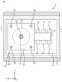
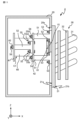
- Circuit diagram of electronic device according to Embodiment 1 Cross-sectional view of a capacitor according to Embodiment 1 Cross-sectional view of electronic device according to Embodiment 1 A sectional view taken along the line IV-IV in FIG. 3 of the electronic device according to Embodiment 1 A sectional view taken along the line V-V in FIG. 4 of the electronic device according to the first embodiment
- a sectional view taken along the line VI-VI in FIG. 3 of the electronic device according to Embodiment 1 A sectional view taken along the line VII-VII in FIG.
- An example of an electronic device is a DC-to-three-phase converter that is mounted on a railway vehicle and converts DC power supplied from a DC power supply into AC power to be supplied to a load device, and supplies the converted AC power to the load device.
- the electronic device 1 according to the first embodiment will be described using a DC-three-phase converter as an example.
- the electronic device 1 shown in FIG. 1 is mounted on a DC feeding type railway vehicle, converts supplied DC power into AC power to be supplied to a load device 71, and supplies the AC power to the load device 71.
- the load device 71 is, for example, a three-phase induction motor that generates propulsive force for a railway vehicle.
- the electronic device 1 has a terminal 1a that is connected to a power source via a contactor, a reactor, etc. (not shown), a terminal 1b that is grounded, and a terminal 1b that converts DC power supplied from the power source into three-phase AC power. It includes a power converter 11 that supplies power to a load device 71, and a capacitor C1 whose both ends are connected to terminals 1a and 1b.
- the terminal 1a is electrically connected to a current collector that obtains DC power supplied from a substation via a power supply line, for example.
- the current collector corresponds to a power source that supplies power to the electronic device 1.
- the power supply line is, for example, an overhead wire or a third rail.
- the current collector is a pantograph or a current collector shoe.
- the terminal 1b is grounded by being short-circuited to a rail via a grounding brush, a grounding ring, a wheel, etc. (not shown).
- the power converter 11 includes three sets of two switching elements 12 connected in series.
- the three sets of switching elements 12 correspond to the U phase, V phase, and W phase of three-phase AC power, respectively.
- Switching element 12 corresponding to U phase, switching element 12 corresponding to V phase, and switching element 12 corresponding to W phase are connected in parallel to each other between terminals 1a and 1b.
- connection point between the two switching elements 12 corresponding to the U phase, the connection point between the two switching elements 12 corresponding to the V phase, and the connection point between the two switching elements 12 corresponding to the W phase are electrically connected to the load device 71, respectively. connected.
- Each switching element 12 includes an IGBT (Insulated Gate Bipolar Transistor) 13 and a free wheel diode 14 whose anode is connected to the emitter terminal of the IGBT 13 and whose cathode is connected to the collector terminal of the IGBT 13. .
- a gate signal from a control section (not shown) is supplied to the gate terminal of the IGBT 13 included in each switching element 12 included in the power conversion section 11 to control on/off of each switching element 12.
- the power converter 11 converts DC power into three-phase AC power, and supplies the three-phase AC power to the load device 71.
- the capacitor C1 is charged with DC power supplied from the power source.
- the capacitor C1 forms an LC filter together with a reactor provided in the circuit between the terminal 1a and the power source, and reduces harmonic components generated by the switching operation of the power converter 11.
- the capacitor C1 includes a case 60 having a cylindrical shape, a plurality of terminals 61 exposed to the outside from one end surface of the case 60, and a mounting portion 62 provided on the other end surface of the case 60.
- a capacitor element 63 housed in a case 60, a lead tab 64 that electrically connects the capacitor element 63 and each terminal 61, and an insulating sealing member 65 that closes an opening of the case 60.
- the case 60 has a cylindrical shape with one end surface open, and the open end surface is closed by a sealing member 65.
- the case 60 included in the capacitor C1 has a cylindrical shape with both ends closed.
- the case 60 is made of a metal member having a cylindrical shape, such as aluminum.
- the case 60 is insulated from each terminal 61 by a sealing member 65.
- the capacitor C1 includes two terminals 61.
- One terminal 61 is electrically connected to the terminal 1a shown in FIG. 1 and the switching elements 12 of the upper arms of the U, V, and W phases of the power converter 11.
- the other terminal 61 is electrically connected to the terminal 1b and the lower arm switching elements 12 of each of the U-phase, V-phase, and W-phase provided in the power conversion section 11.
- the mounting portion 62 is provided on the closed end surface of the case 60, in other words, on the surface of the case 60 opposite to the surface on which each terminal 61 is provided.
- the attachment portion 62 is formed of a threaded protrusion that protrudes from the outer surface of the case 60 in the direction in which the central axis of the case 60 extends.
- the capacitor element 63 has two electrodes and a dielectric sandwiched between the two electrodes.
- the capacitor element 63 is a film capacitor formed by winding a dielectric film on which a positive electrode is formed and a dielectric film on which a negative electrode is formed.
- Each lead tab 64 is formed of a conductor. One lead tab 64 electrically connects one terminal 61 to the positive electrode of the capacitor element 63. The other lead tab 64 electrically connects the other terminal 61 to the negative electrode of the capacitor element 63.
- the sealing member 65 is made of an insulating material such as rubber or resin.
- the sealing member 65 seals the opening of the case 60 and insulates the case 60 and each terminal 61.
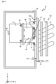
- the electronic device 1 includes a housing 20 that houses the components, a bus bar 15 that is housed in the housing 20 and connects each terminal 61 of the capacitor C1 to the switching element 12, and the housing 20.
- a plate-shaped base 21 that is attached to the base 21 is provided.
- the electronic device 1 further includes a first plate-like member 41 to which the capacitor C1 is attached, a second plate-like member 42 in which a through hole is formed through which the capacitor C1 is inserted, and a second plate-like member to which the first plate member 41 is attached.
- a fixing member is provided, which fixes the capacitor C1 to the base 21 by fixing it to the member 42 and fixing the second plate-like member 42 to the base 21.
- the electronic device 1 includes, as fixed members, a plurality of first rod-shaped members 44 whose one ends are attached to the base 21, and a plurality of first rod-shaped members 44 whose respective one ends are inserted through the second plate-shaped member 42 and attached to the first rod-shaped member 44. It has two rod-like members 45 and a plurality of first fasteners 46 that attach the first plate-like member 41 to the other end of each second rod-like member 45.
- the electronic device 1 further includes a cooling device 30 that is attached to the base 21 and cools the components of the electronic device 1.
- a cooling device 30 that is attached to the base 21 and cools the components of the electronic device 1.
- the X-axis extends in the lateral direction of the casing 20, and the Y-axis extends in the longitudinal direction of the casing 20.
- the X-axis corresponds to the width direction of the car body of the railway vehicle on which the electronic device 1 is mounted
- the Y-axis corresponds to the traveling direction of the railway vehicle.
- the X, Y, and Z axes are orthogonal to each other. When the railway vehicle on which the electronic device 1 is mounted is located in a horizontal place, the Z axis indicates the vertical direction. The same applies to subsequent figures.
- the housing 20 is installed under the floor of the car body of a railway vehicle.
- the casing 20 has such rigidity and strength that it will not deform even when subjected to the expected maximum vibration of the railway vehicle.
- the housing 20 is formed of a metal member such as iron or aluminum.
- An opening 20a is formed in a surface of the casing 20 that intersects with the X-axis.
- the base 21 is removably attached to the housing 20 with the first main surface 21a blocking the opening 20a of the housing 20.
- the base 21 only needs to be firmly attached to the casing 20 to such an extent that the relative positional relationship between the base 21 and the casing 20 does not change even if the base 21 receives vibrations during running of the railway vehicle.
- the base 21 is attached to the outer surface of the housing 20 by an attachment method such as fitting, brazing, welding, adhesion using an adhesive, or fastening using a fastening member.
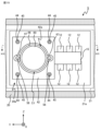
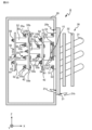
- the base 21 is a heat conductive plate-like member that is attached to the outer surface of the housing 20 while blocking the opening 20a. At least one electronic component that generates heat when energized is attached to the first main surface 21a of the base 21. For example, as shown in FIG. 3 and FIG. 4, which is a sectional view taken along the line IV--IV in FIG. 3, six switching elements 12 are attached to the first main surface 21a of the base 21.
- the capacitor C1 is further fixed to the first main surface 21a of the base 21 by the above-mentioned fixing member.
- the base 21 is made of a material with high thermal conductivity, such as metal such as copper or aluminum, to allow heat to be transferred from the switching element 12 attached to the first main surface 21a to the cooling device 30. It is preferable.
- a cooling device 30 that radiates heat transferred from the switching element 12 attached to the first main surface 21a is attached to the second main surface 21b located opposite to the first main surface 21a.
- the base 21 is attached to the outer surface of the housing 20 with the switching element 12 and the capacitor C1 attached to the first principal surface 21a and the cooling device 30 attached to the second principal surface 21b.
- the cooling device 30 includes a heat pipe 31 attached to the base 21 and a plurality of fins 32 attached to the heat pipe 31 with the heat pipe 31 inserted therethrough.
- the heat pipe 31 is provided on the base 21 and has a main pipe extending in the Y-axis direction and a branch pipe communicating with the main pipe, away from the base 21, and extending vertically upward.
- the main tube is inserted into a groove formed in the base 21 and fixed to the base 21 by a fixing method such as adhesive bonding or soldering.
- the branch pipe is attached to the main pipe by a fixing method such as welding or soldering, and communicates with the main pipe.
- Both the main pipe and branch pipes forming the heat pipe 31 are made of a material with high thermal conductivity, for example, metal such as copper or aluminum.
- a refrigerant is sealed inside the heat pipe 31 .
- the refrigerant is a substance such as water, which is vaporized by heat transferred from the electronic components and liquefied by dissipating the heat to the air around the cooling device 30 via the heat pipes 31 and fins 32.
- the fin 32 is formed of a flat plate member, and is attached to the heat pipe 31 with its main surface parallel to the ZY plane.
- the fins 32 are made of a material with high thermal conductivity, for example, a metal such as copper or aluminum.
- the bus bar 15 electrically connects at least one of the terminals 61 of the capacitor C1 and at least one of the electronic components attached to the base 21. Specifically, the bus bar 15 electrically connects one terminal 61 to the switching element 12 of the upper arm of each of the U phase, V phase, and W phase provided in the power conversion section 11, and connects the other terminal 61 and the switching element 12 of the upper arm of each of the U phase, V phase, and W phase provided The switching elements 12 of the lower arms of each of the U-phase, V-phase, and W-phase included in the conversion unit 11 are electrically connected.
- the bus bar 15 is formed of, for example, a laminate bus bar in which a plurality of conductors and a plurality of insulating layers are laminated.
- the bus bar 15 has a flat plate shape extending along the first main surface 21a of the base 21.
- the capacitor C1 is attached to the first plate member 41. Specifically, the mounting portion 62 of the capacitor C1 is inserted into the through hole formed in the first plate member 41, and the nut 43 is inserted into the mounting portion 62 with the first plate member 41 and the case 60 in contact with each other. By fastening, the capacitor C1 is attached to the first plate member 41.
- the first plate member 41 is formed of a plate member whose main surface has a square shape. It is preferable that the first plate member 41 has enough rigidity and strength that it will not deform even when subjected to the expected maximum vibration of the railway vehicle.
- the first plate-shaped member 41 is formed of a plate-shaped metal member such as iron, stainless steel, or aluminum, or a plate-shaped fiber-reinforced plastic material having a thickness of 10 mm or more.
- the first plate member 41 is formed with an insertion hole 41a through which the first fastener 46 is inserted.
- the second plate member 42 is provided between the first plate member 41 and the base 21, as shown in FIGS. 3 and 5. As shown in FIG. 6, which is a sectional view taken along the line VI-VI in FIG. 3, a through hole 42a is formed in the second plate member 42, into which the capacitor C1 is inserted. The edge of the through hole 42a faces the outer peripheral surface of the case 60 with a space therebetween.
- the second plate member 42 is formed of a plate member whose main surface has a square shape. It is preferable that the second plate member 42 has enough rigidity and strength that it will not deform even when subjected to the expected maximum vibration of the railway vehicle.
- the second plate-shaped member 42 is formed of a plate-shaped metal member such as iron, stainless steel, or aluminum, or a plate-shaped fiber-reinforced plastic material having a thickness of 10 mm or more.
- the second plate member 42 is formed with an insertion hole 42b through which the second rod member 45 is inserted.
- the electronic device 1 includes four first rod-shaped members 44.
- each first rod-shaped member 44 is a hexagonal column with one end tapered. One end of each first rod-shaped member 44 is threaded.
- a first screw hole 44a is formed at the other end of each first rod-shaped member 44. The wall surface of the first screw hole 44a is threaded.
- each first rod-shaped member 44 has such rigidity and strength that it does not deform even when subjected to the expected maximum vibration of the railway vehicle.
- the first rod-shaped member 44 is made of a metal member such as iron, stainless steel, or aluminum, or fiber-reinforced plastic.
- each first rod-shaped member 44 is screwed into a hole 21c formed in the base 21 and whose wall surface is threaded.
- Each first rod member 44 is fixed to the base 21 by screwing one end of each first rod member 44 into the hole 21c.
- the electronic device 1 includes four second rod-shaped members 45.
- each second rod-shaped member 45 is a hexagonal column with one end tapered, similarly to the first rod-shaped member 44.
- One end of each second rod-shaped member 45 is threaded.
- a second screw hole 45a is formed at the other end of each second rod-shaped member 45.
- the wall surface of the second screw hole 45a is threaded.
- each second rod-shaped member 45 has enough rigidity and strength that it will not deform even when subjected to the expected maximum vibration of the railway vehicle.
- the second rod-shaped member 45 is formed of a metal member such as iron, stainless steel, or aluminum, or fiber-reinforced plastic.
- each second rod-shaped member 45 is inserted into the insertion hole 42b of the second plate-shaped member 42 and screwed into the first screw hole 44a of the first rod-shaped member 44.
- the second plate-shaped member 42 is fixed to the base 21 via the first rod-shaped member 44.
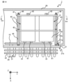
- the electronic device 1 includes four first fasteners 46. As shown in FIG. 5, the first fastener 46 is inserted into the insertion hole 41a of the first plate member 41 and screwed into the second screw hole 45a of the second rod member 45. As shown in FIG. By attaching the first fastener 46 to the second rod-shaped member 45 as described above, the first plate-shaped member 41 is fixed to the base 21 via the second rod-shaped member 45 and the first rod-shaped member 44.
- the capacitor C1 is attached to the base 21 by the fixing members attached to each other as described above. Specifically, the capacitor C1 is fixed to the base 21 via the first plate member 41, the first fastener 46, the second rod member 45, and the first rod member 44.
- the casing 20 attached to the vehicle body vibrates. Vibration is transmitted from the casing 20 to the capacitor C1 via the base 21, the first bar member 44, the second bar member 45, the first fastener 46, and the first plate member 41.
- the first rod-shaped member 44 has one end fixed to the base 21 as a fulcrum, and the other end vibrates. The magnitude of vibration at the other end of the first rod-shaped member 44 is proportional to the length of the first rod-shaped member 44 in the extending direction.
- the second rod-shaped member 45 has one end fixed to the first rod-shaped member 44 as a fulcrum, and the other end vibrates. The magnitude of the vibration at the other end of the second rod-shaped member 45 is proportional to the length of the second rod-shaped member 45 in the extending direction.
- each of the first rod-like member 44 and the second rod-like member 45 in the extending direction is shorter than that of a single member that extends from the mounting portion of the capacitor to the base and fixes the capacitor to the base. Therefore, the vibration of the capacitor C1 included in the electronic device 1 is smaller than that of the capacitor fixed to the base using a single member.
- the capacitor C1 is fixed to the base 21 by the fixing member including the first rod-shaped member 44, the second rod-shaped member 45, and the first fastener 46. Since the capacitor C1 is fixed to the base 21 by the fixing member, the vibration of the capacitor C1 is small.
- the capacitor C1 is attached to the base 21 with each terminal 61 facing the base 21. Therefore, the distance of the bus bar 15 connecting each terminal 61 and each switching element 12 attached to the base 21 can be minimized.
- the bus bar 15 can be shaped like a flat plate along the first main surface 21a of the base 21. Therefore, the arrangement path of the bus bar 15 is simplified, and the structure of the electronic device 1 is simple. By shortening the distance between the bus bars 15, the parasitic inductance of the bus bars 15 is reduced, and the manufacturing cost of the electronic device 1 is also reduced.
- the potential of the case 60 of the capacitor C1 becomes the same potential as that of the casing 20. Therefore, if the housing 20 is grounded, the case 60 of the capacitor C1 is grounded.
- the structure for fixing the capacitor C1 to the base 21 is not limited to the above-mentioned example, and any structure can be used as long as the capacitor C1 can be fixed to the base 21 via a plurality of members.
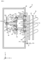
- An electronic device 2 in which a capacitor C1 is fixed to a base 21 with a structure different from that of the first embodiment will be described in a second embodiment, focusing on the differences from the first embodiment.
- the electronic device 2 shown in FIG. 8 includes a plurality of second plate members 42 and 47.
- the plurality of second plate members 42 and 47 are provided between the first plate member 41 and the base 21, and among the plurality of second plate members 42 and 47, the second plate member 47 is 1 is provided at a position adjacent to the plate-shaped member 41.
- the electronic device 2 has a plurality of first rod-like members 44 whose one ends are attached to the base 21 as fixed members, between the second plate-like members 42 and 47, and between the first plate-like member 41 and the second plate-like member 47. It has a plurality of third rod-shaped members 48 and 49 each provided between them, and a plurality of second fasteners 50 that attach the first plate-shaped member 41 to the third rod-shaped member 49.
- the shapes of the second plate members 42 and 47 are the same. Similar to the second plate member 42, the second plate member 47 has a through hole through which the capacitor C1 is inserted. The edge of the through hole faces the outer peripheral surface of the case 60 with a space therebetween.
- the second plate member 47 is formed of a plate member whose main surface has a square shape. It is preferable that the second plate-shaped member 47 has such rigidity and strength that it does not deform even when subjected to the expected maximum vibration of the railway vehicle.
- the second plate-shaped member 47 is formed of a plate-shaped metal member such as iron, stainless steel, or aluminum, or a plate-shaped fiber-reinforced plastic material having a thickness of 10 mm or more.
- the second plate member 47 is formed with an insertion hole 47a through which the third rod member 49 is inserted.
- the electronic device 2 includes four first rod-shaped members 44.
- the electronic device 2 further includes four third rod members 48 each having one end attached to the first rod member 44 and four third rod members 49 each having one end attached to the third rod member 48. .
- Each third rod-shaped member 48 is provided between the second plate-shaped members 42 and 47 adjacent to each other.
- Each of the third rod-shaped members 48 is a hexagonal column having a tapered shape at one end, similarly to the first rod-shaped member 44 .
- One end of each third rod-shaped member 48 is threaded.
- a third screw hole 48a is formed at the other end of each third rod-shaped member 48.
- the wall surface of the third screw hole 48a is threaded.
- each third rod-shaped member 48 has enough rigidity and strength that it will not deform even when subjected to the expected maximum vibration of the railway vehicle.
- the third rod-shaped member 48 is made of a metal member such as iron, stainless steel, or aluminum, or fiber-reinforced plastic.
- each third rod-shaped member 48 is inserted into the insertion hole 42b of the second plate-shaped member 42 and screwed into the first screw hole 44a of the first rod-shaped member 44.
- the third rod-shaped member 48 is inserted into the insertion hole 42b of the second plate-shaped member 42 and screwed into the first screw hole 44a of the first rod-shaped member 44.
- Each third rod member 49 is provided between the first plate member 41 and the second plate member 47.
- each third rod-like member 49 is a hexagonal column having a tapered shape at one end. One end of each third rod-shaped member 49 is threaded.
- a third screw hole 49a is formed at the other end of each third rod-shaped member 49. The wall surface of the third screw hole 49a is threaded. It is preferable that each third rod-shaped member 49 has enough rigidity and strength that it will not deform even when subjected to the expected maximum vibration of the railway vehicle.
- the third rod-shaped member 49 is formed of a metal member such as iron, stainless steel, or aluminum, or fiber-reinforced plastic.
- each third rod-like member 49 is inserted into the insertion hole 47a of the second plate-like member 47, and a third screw hole 48a of the third rod-like member 48 is provided at a position adjacent to the third rod-like member 49. to be screwed together.
- the third rod-shaped members 48 and 49 are attached to each other.
- the second plate-shaped member 47 is fixed to the base 21 via the third rod-shaped member 48 and the first rod-shaped member 44.
- the electronic device 2 includes four second fasteners 50 attached to the third rod-shaped member 49.
- the second fastener 50 is inserted into the insertion hole 41 a of the first plate member 41 and screwed into the third screw hole 49 a of the third rod member 49 .
- the first plate-shaped member 41 is attached to the base 21 via the third rod-shaped member 49, the third rod-shaped member 48, and the first rod-shaped member 44. Fixed.
- the capacitor C1 is attached to the base 21 by the fixing members attached to each other as described above. Specifically, the capacitor C1 is fixed to the base 21 via the first plate member 41, the first fastener 50, the third rod member 49, the third rod member 48, and the first rod member 44.
- the capacitor C1 is fixed to the base 21 by the fixing member having the first bar member 44, the third bar members 48, 49, and the first fastener 50. Ru. Since the capacitor C1 is fixed to the base 21 by the fixing member, the vibration of the capacitor C1 is small. Compared to the first embodiment, since the capacitor C1 is fixed to the base 21 through more members, the vibration of the capacitor C1 included in the electronic device 2 is smaller.
- the structure for fixing the capacitor C1 to the base 21 is not limited to the above-mentioned example, and any structure can be used as long as the capacitor C1 can be fixed to the base 21 via a plurality of members.
- An electronic device 3 in which a capacitor C1 is fixed to a base 21 with a structure different from that of the first and second embodiments will be described in a third embodiment, focusing on the differences from the first embodiment.
- the electronic device 3 according to the third embodiment shown in FIG. 10 and FIG. 11, which is a sectional view taken along the line XI-XI in FIG. It includes a spacer 51 and a plurality of second spacers 52 that come into contact with the first plate member 41 and the second plate member 42 .
- the electronic device 3 includes, as fixing members, a first fastening member 53 that fixes the first spacer 51 to the base 21, a second fastening member 54 that fixes the second plate member 42 to the first spacer 51, and a second spacer. 52 to the second plate-like member 42 , and a fourth fastening member 56 to fix the first plate-like member 41 to the second spacer 52 .
- the electronic device 3 includes four first spacers 51.
- Each first spacer 51 is formed of a columnar member having a T-shaped cross section perpendicular to the Y-axis. It is preferable that the first spacer 51 has such rigidity and strength that it will not be deformed even when subjected to the expected maximum vibration of the railway vehicle.
- the first spacer 51 is made of, for example, a metal member such as stainless steel or aluminum, or fiber-reinforced plastic. As an example, the first spacer 51 is formed by cutting out a metal block.
- the electronic device 3 includes two second spacers 52.
- Each second spacer 52 is formed of a columnar member having a T-shaped cross section perpendicular to the Y-axis. It is preferable that the second spacer 52 has such rigidity and strength that it will not deform even when subjected to the expected maximum vibration of the railway vehicle.
- the second spacer 52 is made of, for example, a metal member such as stainless steel or aluminum, or fiber-reinforced plastic. As an example, the second spacer 52 is formed by cutting out a metal block.
- the base 21 is formed with a hole 21d into which the first fastening member 53 is inserted.
- the wall surface of the hole 21d is threaded.
- the first plate member 41 is formed with an insertion hole 41b through which the fourth fastening member 56 is inserted.
- the second plate member 42 is formed with an insertion hole 42c through which the second fastening member 54 is inserted and an insertion hole 42d through which the third fastening member 55 is inserted.
- Two insertion holes 51a are formed in one end of the first spacer 51 that contacts the base 21, into which the first fastening member 53 is inserted, and in the other end of the first spacer 51, a second fastening member 54 is inserted.
- a first fastening hole 51b is formed.
- the wall surface of the first fastening hole 51b is threaded.
- Two insertion holes 52a through which the third fastening member 55 is inserted are formed at one end of the second spacer 52 that contacts the second plate member 42, and a fourth fastening member is formed at the other end of the second spacer 52.
- a second fastening hole 52b into which the second fastening hole 56 is inserted is formed.
- the first fastening member 53 has such rigidity and strength that it will not deform even when subjected to the expected maximum vibration of the railway vehicle.
- the first fastening member 53 is formed of a metal member such as iron, stainless steel, or aluminum, or fiber-reinforced plastic.
- the first fastening member 53 is, for example, a bolt whose tip is threaded, and is screwed into the hole 21d. Specifically, the first fastening member 53 is inserted into the insertion hole 51a of the first spacer 51 that is in contact with the base 21, and is screwed into the hole 21d of the base 21. As a result, the first spacer 51 is fixed to the base 21.
- the second fastening member 54 has such rigidity and strength that it will not deform even when subjected to the expected maximum vibration of the railway vehicle.
- the second fastening member 54 is formed of a metal member such as iron, stainless steel, or aluminum, or fiber-reinforced plastic.
- the second fastening member 54 is, for example, a bolt whose tip is threaded, and is screwed into the first fastening hole 51b of the first spacer 51. Specifically, the second fastening member 54 is inserted into the insertion hole 42c of the second plate member 42 that is in contact with the first spacer 51, and is screwed into the first fastening hole 51b of the first spacer 51. As a result, the second plate member 42 is fixed to the first spacer 51. As described above, by attaching the second fastening member 54 to the first spacer 51, the second plate member 42 is fixed to the base 21 via the first spacer 51.
- the third fastening member 55 includes a bolt 55a whose tip is threaded, and a nut 55b having an inner circumferential surface that is screwed into the bolt 55a. It is preferable that the third fastening member 55 has such rigidity and strength that it will not deform even when subjected to the expected maximum vibration of the railway vehicle.
- the third fastening member 55 is formed of a metal member such as iron, stainless steel, or aluminum, or fiber-reinforced plastic.
- the second spacer 52 is inserted into the second plate-like member 42. Fixed. As a result, the second spacer 52 is fixed to the base 21 via the second plate member 42 and the first spacer 51.
- the fourth fastening member 56 has such rigidity and strength that it will not deform even when subjected to the expected maximum vibration of the railway vehicle.
- the fourth fastening member 56 is formed of a metal member such as iron, stainless steel, or aluminum, or fiber reinforced plastic.
- the fourth fastening member 56 is, for example, a bolt whose tip is threaded, and is screwed into the second fastening hole 52b of the second spacer 52. Specifically, the fourth fastening member 56 is inserted into the insertion hole 41b of the first plate member 41 and screwed into the second fastening hole 52b of the second spacer 52. As a result, the first plate member 41 is fixed to the second spacer 52. As described above, by attaching the fourth fastening member 56 to the second spacer 52, the first plate member 41 is attached to the base 21 via the second spacer 52, the second plate member 42, and the first spacer 51. Fixed.
- the capacitor C1 is attached to the base 21 by the fixing members attached to each other as described above.
- the capacitor C1 includes the first plate member 41, the fourth fastening member 56, the second spacer 52, the third fastening member 55, the second plate member 42, the second fastening member 54, the first spacer 51, and It is fixed to the base 21 via the first fastening member 53.
- the first spacer 51, the second spacer 52, the first fastening member 53, the second fastening member 54, the third fastening member 55, and the fourth fastening member 56 Capacitor C1 is fixed to base 21 by a fixing member having. Since the first spacer 51 and the second spacer 52 are arranged, the vibration of the capacitor C1 included in the electronic device 3 is small.
- the structure for fixing the capacitor C1 to the base 21 is not limited to the above-mentioned example, and any structure can be used as long as the capacitor C1 can be fixed to the base 21 via a plurality of members.
- An electronic device 4 in which a capacitor C1 is fixed to a base 21 with a structure different from that in Embodiment 1-3 will be described in Embodiment 4, focusing on the differences from Embodiment 1.
- the electronic device 4 includes the second plate-like member 42 and four first spacers 51 that come into contact with the base 21.
- the electronic device 4 includes a first plate member 57 having a shape extending toward the base 21 from the other end surface of the case 60, specifically, from the end surface where the mounting portion 62 is provided.
- the electronic device 4 includes, as fixing members, a first fastening member 53 that fixes the first spacer 51 to the base 21 and a second fastening member that fixes the first plate member 57 and the second plate member 42 to the first spacer 51. It has a member 54.
- the first plate member 57 is formed by bending a flat plate member. A portion of the first plate member 57 contacts the second plate member 42 .
- the second fastening member 54 is inserted through the first plate-like member 57 and the second plate-like member 42 that are in contact with each other, and is screwed into a first fastening hole (not shown) of the first spacer 51.
- the first plate member 57 is fixed to the base 21 via the second plate member 42 and the first spacer 51.
- the capacitor C1 is fixed to the base 21 by the fixing member including the first spacer 51, the first fastening member 53, and the second fastening member 54. Since the first spacer 51 is arranged, the vibration of the capacitor C1 included in the electronic device 4 is small.
- the electronic device 1 includes a first spacer 51 and a first fastening member 53 instead of the first rod-like member 44, and the second rod-like member 45 is screwed into the first fastening hole 51b of the first spacer 51. It's okay.
- the capacitor C1 included in the electronic device 5 may include a mounting portion 66 that covers the outer peripheral surface of the case 60 and is attached to the case 60.
- the attachment portion 66 has two protrusions 67 that protrude in a direction away from the outer peripheral surface of the case 60.
- the electronic device 5 includes a bolt 58 that is inserted through the protrusion 67 and the first plate member 41 and has a threaded tip, and a nut 59 that is screwed onto the bolt 58.
- the capacitor C1 is fixed to the first plate member 41 by screwing the bolt 58 and the nut 59 together.
- the case 60 of the capacitor C1 included in the electronic device 6 may have two protrusions 67 protruding from the outer peripheral surface of the case 60.
- the protrusion 67 may be formed integrally with the case 60.
- the capacitor C1 is fixed to the first plate member 41 by screwing the bolt 58 inserted through the protrusion 67 and the first plate member 41 with the nut 59. .
- the electronic device 1-6 includes one capacitor C1, the number of capacitors is arbitrary.
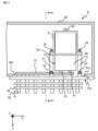
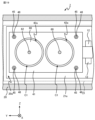
- An electronic device 7 including a plurality of capacitors C1 is shown in FIGS. 18 and 19.
- the electronic device 7 includes two capacitors C1 arranged in the Y-axis direction.
- the electronic device 7 includes a fixing member similar to the electronic device 1.
- the attachment portion 62 of each capacitor C1 is inserted into the first plate member 41, and the nut 43 is fastened to the attachment portion 62, so that each capacitor C1 is attached to the first plate member 41.
- a first plate member 41 to which two capacitors C1 are attached is fixed to the base 21 by a first rod member 44, a second rod member 45, and a first fastener 46, as in the first embodiment. .
- two capacitors C1 are fixed to the base 21.
- the number of second plate members 42, 47 included in the electronic device 2 is not limited to two as in the above example, but is any number greater than or equal to two.
- the electronic device 2 further includes one or more second plate members 47 and a plurality of third rod members 48 provided between the second plate members 47 adjacent to each other. and may also be provided.
- FIG. 20 shows an electronic device 8 including a plurality of second plate members 42.
- the electronic device 8 has a plurality of second plate-like members 42 , a position where the second plate-like members 42 of the plurality of second plate-like members 42 are in contact with each other, and a position where the first plate-like member 41 and the second plate-like member 42 contact each other.
- the second plate-like member 42 is provided at a position adjacent to the first plate-like member 41, and a plurality of second spacers 52 are provided at positions in contact with the second plate-like member 42.
- the first fastening member 53 fixes the first spacer 51 to the base 21.
- the second fastening member 54 fixes the second plate member 42 that contacts the first spacer 51 to the first spacer 51 .
- the third fastening member 55 fixes the second spacer 52 to the second plate member 42 that abuts the second spacer 52 .
- the fourth fastening member 56 fixes the first plate member 41 to the second spacer 52 that abuts the first plate member 41 .
- the circuit configuration of the power conversion unit 11 is not limited to the above example, and may be any circuit as long as it includes the switching element 12, which is an electronic component that generates heat.
- An elastic member may be provided in the gap between the through hole 42a and the case 60. The provision of the elastic member prevents the capacitor C1 from coming into contact with the second plate member 42 when the capacitor C1 vibrates.
- the shapes of the main surfaces of the first plate-like member 41 and the second plate-like members 42, 47 are not limited to square, but may be rectangular, circular, oval, etc.
- the capacitor C1 is not limited to the above example, but is arbitrary. As an example, a three-terminal capacitor may be used as the capacitor C1.
- the shape of the case 60 is not limited to the above example, and may have a cylindrical shape with a square or rectangular outer shape.
- the first fastening member 53, the second fastening member 54, the third fastening member 55, and the fourth fastening member 56 may be fastened by riveting.
- fastening is performed by riveting, the above-mentioned thread cutting process is not necessary.
- the load device 71 is not limited to an electric motor, but is any electronic device such as a lighting device or an air conditioner that operates by receiving power from the electronic device 1-8.
- the circuit configuration of the electronic device 1-8 is not limited to the above-mentioned example, and may be any circuit as long as it includes the capacitor C1.
- the electronic device 1-8 may be a power conversion device that converts AC power supplied from a power source into AC power to be supplied to the load device 71.
- the orientation in which the electronic device 1-8 is installed is not limited to the above example.
- the first main surface 21a of the base 21 may be attached to a railway vehicle in a horizontal direction.
- the first main surface 21a of the base 21 may be attached to a railway vehicle in a direction perpendicular to the traveling direction of the railway vehicle.
- the electronic device 1-8 is not limited to being provided under the floor of the car body of the railway vehicle, but may be provided on the roof of the car body of the railway vehicle.
- the electronic device 1-8 is not limited to a DC-feeding railway vehicle, but may be mounted on an AC-feeding railway vehicle.
- the AC power obtained by the current collector from the substation via the power supply line is stepped down by the transformer, and converted from AC power to DC by the converter.
- the DC power that is converted into electric power and output by the converter may be supplied to the electronic device 1-8.
- the electronic device 1-8 is not limited to a railway vehicle, and may be mounted on any moving body such as an automobile, an aircraft, or a ship, or may be installed at any location subject to vibration.
Landscapes
- Engineering & Computer Science (AREA)
- Power Engineering (AREA)
- Microelectronics & Electronic Packaging (AREA)
- Manufacturing & Machinery (AREA)
- Electric Propulsion And Braking For Vehicles (AREA)
- Electric Double-Layer Capacitors Or The Like (AREA)
- Mounting Components In General For Electric Apparatus (AREA)
Priority Applications (6)
| Application Number | Priority Date | Filing Date | Title |
|---|---|---|---|
| JP2024509606A JP7555520B2 (ja) | 2022-03-24 | 2022-03-24 | 電子機器 |
| EP22933431.3A EP4503073A4 (en) | 2022-03-24 | 2022-03-24 | ELECTRONIC DEVICE |
| US18/728,988 US20250112561A1 (en) | 2022-03-24 | 2022-03-24 | Electronic apparatus |
| DE112022006891.4T DE112022006891T5 (de) | 2022-03-24 | 2022-03-24 | Elektronische einrichtung |
| PCT/JP2022/014116 WO2023181291A1 (ja) | 2022-03-24 | 2022-03-24 | 電子機器 |
| CN202290000897.6U CN223218129U (zh) | 2022-03-24 | 2022-03-24 | 电子设备 |
Applications Claiming Priority (1)
| Application Number | Priority Date | Filing Date | Title |
|---|---|---|---|
| PCT/JP2022/014116 WO2023181291A1 (ja) | 2022-03-24 | 2022-03-24 | 電子機器 |
Publications (1)
| Publication Number | Publication Date |
|---|---|
| WO2023181291A1 true WO2023181291A1 (ja) | 2023-09-28 |
Family
ID=88100693
Family Applications (1)
| Application Number | Title | Priority Date | Filing Date |
|---|---|---|---|
| PCT/JP2022/014116 Ceased WO2023181291A1 (ja) | 2022-03-24 | 2022-03-24 | 電子機器 |
Country Status (6)
| Country | Link |
|---|---|
| US (1) | US20250112561A1 (https=) |
| EP (1) | EP4503073A4 (https=) |
| JP (1) | JP7555520B2 (https=) |
| CN (1) | CN223218129U (https=) |
| DE (1) | DE112022006891T5 (https=) |
| WO (1) | WO2023181291A1 (https=) |
Citations (6)
| Publication number | Priority date | Publication date | Assignee | Title |
|---|---|---|---|---|
| JPH052589U (ja) * | 1991-06-19 | 1993-01-14 | 株式会社東芝 | インバータ装置 |
| JP2002252327A (ja) | 2001-02-26 | 2002-09-06 | Hitachi Ltd | 電力変換装置 |
| JP2005353894A (ja) * | 2004-06-11 | 2005-12-22 | Hitachi Aic Inc | ケース入りコンデンサ |
| JP2010123651A (ja) * | 2008-11-18 | 2010-06-03 | Panasonic Corp | 大型コンデンサの固定構造 |
| JP2013171995A (ja) * | 2012-02-21 | 2013-09-02 | Hitachi Aic Inc | コンデンサユニット |
| JP2019195003A (ja) * | 2016-09-07 | 2019-11-07 | パナソニックIpマネジメント株式会社 | 電子部品実装体および電子制御装置、ならびにサーボモータ |
Family Cites Families (15)
| Publication number | Priority date | Publication date | Assignee | Title |
|---|---|---|---|---|
| JPS59171324U (ja) * | 1983-04-30 | 1984-11-16 | 日本電気ホームエレクトロニクス株式会社 | 電子部品の保持装置 |
| JPS61109131U (https=) * | 1984-12-21 | 1986-07-10 | ||
| JP2003283072A (ja) * | 2002-03-20 | 2003-10-03 | Canon Inc | プリント配線板ユニット |
| JP4305730B2 (ja) * | 2003-04-01 | 2009-07-29 | 日立エーアイシー株式会社 | 金属製の有底筒状ケース入りコンデンサの製造方法およびそのケースの製造方法 |
| US8194393B2 (en) * | 2007-02-16 | 2012-06-05 | Panasonic Corporation | Capacitor unit and its manufacturing method |
| JP5018119B2 (ja) * | 2007-02-16 | 2012-09-05 | パナソニック株式会社 | 蓄電ユニット |
| DE102012202539A1 (de) * | 2012-02-20 | 2013-08-22 | Siemens Aktiengesellschaft | Montagebaugruppe für elektrische oder elektronische Bauelemente |
| JP5975916B2 (ja) * | 2013-03-22 | 2016-08-23 | 株式会社日立製作所 | コンデンサ装置および電力変換装置 |
| US9179544B1 (en) * | 2014-04-28 | 2015-11-03 | General Electric Company | Method and apparatus for mechanical load reduction on the electrical terminals of a capacitor |
| DE102014116058B3 (de) * | 2014-11-04 | 2015-12-17 | Semikron Elektronik Gmbh & Co. Kg | Leistungshalbleitereinrichtung |
| JP6493788B2 (ja) * | 2015-02-24 | 2019-04-03 | 日立金属株式会社 | アンテナ装置 |
| CN104916431A (zh) * | 2015-05-26 | 2015-09-16 | 浙江海得新能源有限公司 | 一种电容固定安装结构 |
| DE102016112777B4 (de) * | 2016-07-12 | 2021-03-18 | Semikron Elektronik Gmbh & Co. Kg | Leistungshalbleitereinrichtung |
| KR102534240B1 (ko) * | 2017-06-30 | 2023-05-18 | 교세라 에이브이엑스 컴포넌츠 코포레이션 | 울트라커패시터 모듈용 밸런싱 회로로부터 열 소산 |
| JP2020181919A (ja) * | 2019-04-26 | 2020-11-05 | 株式会社豊田自動織機 | 半導体装置 |
-
2022
- 2022-03-24 WO PCT/JP2022/014116 patent/WO2023181291A1/ja not_active Ceased
- 2022-03-24 EP EP22933431.3A patent/EP4503073A4/en active Pending
- 2022-03-24 DE DE112022006891.4T patent/DE112022006891T5/de active Pending
- 2022-03-24 CN CN202290000897.6U patent/CN223218129U/zh active Active
- 2022-03-24 JP JP2024509606A patent/JP7555520B2/ja active Active
- 2022-03-24 US US18/728,988 patent/US20250112561A1/en active Pending
Patent Citations (6)
| Publication number | Priority date | Publication date | Assignee | Title |
|---|---|---|---|---|
| JPH052589U (ja) * | 1991-06-19 | 1993-01-14 | 株式会社東芝 | インバータ装置 |
| JP2002252327A (ja) | 2001-02-26 | 2002-09-06 | Hitachi Ltd | 電力変換装置 |
| JP2005353894A (ja) * | 2004-06-11 | 2005-12-22 | Hitachi Aic Inc | ケース入りコンデンサ |
| JP2010123651A (ja) * | 2008-11-18 | 2010-06-03 | Panasonic Corp | 大型コンデンサの固定構造 |
| JP2013171995A (ja) * | 2012-02-21 | 2013-09-02 | Hitachi Aic Inc | コンデンサユニット |
| JP2019195003A (ja) * | 2016-09-07 | 2019-11-07 | パナソニックIpマネジメント株式会社 | 電子部品実装体および電子制御装置、ならびにサーボモータ |
Non-Patent Citations (1)
| Title |
|---|
| See also references of EP4503073A4 |
Also Published As
| Publication number | Publication date |
|---|---|
| US20250112561A1 (en) | 2025-04-03 |
| JPWO2023181291A1 (https=) | 2023-09-28 |
| DE112022006891T5 (de) | 2025-01-02 |
| EP4503073A1 (en) | 2025-02-05 |
| CN223218129U (zh) | 2025-08-12 |
| EP4503073A4 (en) | 2025-10-22 |
| JP7555520B2 (ja) | 2024-09-24 |
Similar Documents
| Publication | Publication Date | Title |
|---|---|---|
| US11296613B2 (en) | Power conversion device | |
| US20160037654A1 (en) | Power Converter | |
| US11588413B2 (en) | Power conversion device | |
| WO2014061447A1 (ja) | 電力変換装置 | |
| JP2000152662A (ja) | 電源平滑用コンデンサ搭載型インバータ装置 | |
| JP4538474B2 (ja) | インバータ装置 | |
| JPWO2015053139A1 (ja) | 電力変換装置 | |
| JP2015100223A (ja) | 電力変換装置 | |
| JP2013169075A (ja) | 電力変換装置 | |
| US12043130B2 (en) | Cooling structure, charging apparatus, and vehicle | |
| WO2015083476A1 (ja) | 電力変換装置 | |
| JP6647350B2 (ja) | 電力変換装置 | |
| JP7555520B2 (ja) | 電子機器 | |
| WO2019193903A1 (ja) | 電力変換装置及びコンデンサモジュール | |
| JP7180265B2 (ja) | 電力変換装置 | |
| JP7005732B1 (ja) | 電力変換装置及びその製造方法 | |
| CN120226107A (zh) | 电容器装置 | |
| JP7294247B2 (ja) | 電気ユニット | |
| JP2019062739A (ja) | 電力変換装置 | |
| JP6932219B1 (ja) | 電力変換装置 | |
| WO2023203754A1 (ja) | コンデンサユニットおよび電子機器 | |
| JP4421132B2 (ja) | 鉄道車両用電力変換装置 | |
| JP7507974B2 (ja) | 電子機器 | |
| JP2017204917A (ja) | 電力変換装置 | |
| US12487256B2 (en) | Voltage sensor and power conversion device |
Legal Events
| Date | Code | Title | Description |
|---|---|---|---|
| 121 | Ep: the epo has been informed by wipo that ep was designated in this application |
Ref document number: 22933431 Country of ref document: EP Kind code of ref document: A1 |
|
| WWE | Wipo information: entry into national phase |
Ref document number: 2024509606 Country of ref document: JP |
|
| WWE | Wipo information: entry into national phase |
Ref document number: 18728988 Country of ref document: US |
|
| WWE | Wipo information: entry into national phase |
Ref document number: 202427068038 Country of ref document: IN |
|
| WWE | Wipo information: entry into national phase |
Ref document number: 202290000897.6 Country of ref document: CN |
|
| WWE | Wipo information: entry into national phase |
Ref document number: 112022006891 Country of ref document: DE Ref document number: 2022933431 Country of ref document: EP |
|
| ENP | Entry into the national phase |
Ref document number: 2022933431 Country of ref document: EP Effective date: 20241024 |
|
| WWP | Wipo information: published in national office |
Ref document number: 18728988 Country of ref document: US |
|
| WWP | Wipo information: published in national office |
Ref document number: 202290000897.6 Country of ref document: CN |