WO2023176200A1 - 塗工装置および塗膜付きウェブの製造方法 - Google Patents
塗工装置および塗膜付きウェブの製造方法 Download PDFInfo
- Publication number
- WO2023176200A1 WO2023176200A1 PCT/JP2023/004046 JP2023004046W WO2023176200A1 WO 2023176200 A1 WO2023176200 A1 WO 2023176200A1 JP 2023004046 W JP2023004046 W JP 2023004046W WO 2023176200 A1 WO2023176200 A1 WO 2023176200A1
- Authority
- WO
- WIPO (PCT)
- Prior art keywords
- coating
- web
- bar
- coating liquid
- width direction
- Prior art date
- Legal status (The legal status is an assumption and is not a legal conclusion. Google has not performed a legal analysis and makes no representation as to the accuracy of the status listed.)
- Ceased
Links
Images







Classifications
-
- B—PERFORMING OPERATIONS; TRANSPORTING
- B05—SPRAYING OR ATOMISING IN GENERAL; APPLYING FLUENT MATERIALS TO SURFACES, IN GENERAL
- B05C—APPARATUS FOR APPLYING FLUENT MATERIALS TO SURFACES, IN GENERAL
- B05C1/00—Apparatus in which liquid or other fluent material is applied to the surface of the work by contact with a member carrying the liquid or other fluent material, e.g. a porous member loaded with a liquid to be applied as a coating
- B05C1/04—Apparatus in which liquid or other fluent material is applied to the surface of the work by contact with a member carrying the liquid or other fluent material, e.g. a porous member loaded with a liquid to be applied as a coating for applying liquid or other fluent material to work of indefinite length
- B05C1/08—Apparatus in which liquid or other fluent material is applied to the surface of the work by contact with a member carrying the liquid or other fluent material, e.g. a porous member loaded with a liquid to be applied as a coating for applying liquid or other fluent material to work of indefinite length using a roller or other rotating member which contacts the work along a generating line
- B05C1/0813—Apparatus in which liquid or other fluent material is applied to the surface of the work by contact with a member carrying the liquid or other fluent material, e.g. a porous member loaded with a liquid to be applied as a coating for applying liquid or other fluent material to work of indefinite length using a roller or other rotating member which contacts the work along a generating line characterised by means for supplying liquid or other fluent material to the roller
-
- B—PERFORMING OPERATIONS; TRANSPORTING
- B05—SPRAYING OR ATOMISING IN GENERAL; APPLYING FLUENT MATERIALS TO SURFACES, IN GENERAL
- B05C—APPARATUS FOR APPLYING FLUENT MATERIALS TO SURFACES, IN GENERAL
- B05C1/00—Apparatus in which liquid or other fluent material is applied to the surface of the work by contact with a member carrying the liquid or other fluent material, e.g. a porous member loaded with a liquid to be applied as a coating
- B05C1/04—Apparatus in which liquid or other fluent material is applied to the surface of the work by contact with a member carrying the liquid or other fluent material, e.g. a porous member loaded with a liquid to be applied as a coating for applying liquid or other fluent material to work of indefinite length
- B05C1/08—Apparatus in which liquid or other fluent material is applied to the surface of the work by contact with a member carrying the liquid or other fluent material, e.g. a porous member loaded with a liquid to be applied as a coating for applying liquid or other fluent material to work of indefinite length using a roller or other rotating member which contacts the work along a generating line
- B05C1/086—Apparatus in which liquid or other fluent material is applied to the surface of the work by contact with a member carrying the liquid or other fluent material, e.g. a porous member loaded with a liquid to be applied as a coating for applying liquid or other fluent material to work of indefinite length using a roller or other rotating member which contacts the work along a generating line a pool of coating material being formed between a roller, e.g. a dosing roller and an element cooperating therewith
-
- B—PERFORMING OPERATIONS; TRANSPORTING
- B05—SPRAYING OR ATOMISING IN GENERAL; APPLYING FLUENT MATERIALS TO SURFACES, IN GENERAL
- B05C—APPARATUS FOR APPLYING FLUENT MATERIALS TO SURFACES, IN GENERAL
- B05C1/00—Apparatus in which liquid or other fluent material is applied to the surface of the work by contact with a member carrying the liquid or other fluent material, e.g. a porous member loaded with a liquid to be applied as a coating
- B05C1/04—Apparatus in which liquid or other fluent material is applied to the surface of the work by contact with a member carrying the liquid or other fluent material, e.g. a porous member loaded with a liquid to be applied as a coating for applying liquid or other fluent material to work of indefinite length
- B05C1/08—Apparatus in which liquid or other fluent material is applied to the surface of the work by contact with a member carrying the liquid or other fluent material, e.g. a porous member loaded with a liquid to be applied as a coating for applying liquid or other fluent material to work of indefinite length using a roller or other rotating member which contacts the work along a generating line
- B05C1/0847—Apparatus in which liquid or other fluent material is applied to the surface of the work by contact with a member carrying the liquid or other fluent material, e.g. a porous member loaded with a liquid to be applied as a coating for applying liquid or other fluent material to work of indefinite length using a roller or other rotating member which contacts the work along a generating line the circumferential speed of the coating roller and the work speed having same direction but different value
-
- B—PERFORMING OPERATIONS; TRANSPORTING
- B05—SPRAYING OR ATOMISING IN GENERAL; APPLYING FLUENT MATERIALS TO SURFACES, IN GENERAL
- B05C—APPARATUS FOR APPLYING FLUENT MATERIALS TO SURFACES, IN GENERAL
- B05C1/00—Apparatus in which liquid or other fluent material is applied to the surface of the work by contact with a member carrying the liquid or other fluent material, e.g. a porous member loaded with a liquid to be applied as a coating
- B05C1/04—Apparatus in which liquid or other fluent material is applied to the surface of the work by contact with a member carrying the liquid or other fluent material, e.g. a porous member loaded with a liquid to be applied as a coating for applying liquid or other fluent material to work of indefinite length
- B05C1/16—Apparatus in which liquid or other fluent material is applied to the surface of the work by contact with a member carrying the liquid or other fluent material, e.g. a porous member loaded with a liquid to be applied as a coating for applying liquid or other fluent material to work of indefinite length only at particular parts of the work
- B05C1/165—Apparatus in which liquid or other fluent material is applied to the surface of the work by contact with a member carrying the liquid or other fluent material, e.g. a porous member loaded with a liquid to be applied as a coating for applying liquid or other fluent material to work of indefinite length only at particular parts of the work using a roller or other rotating member which contacts the work along a generating line
-
- B—PERFORMING OPERATIONS; TRANSPORTING
- B05—SPRAYING OR ATOMISING IN GENERAL; APPLYING FLUENT MATERIALS TO SURFACES, IN GENERAL
- B05D—PROCESSES FOR APPLYING FLUENT MATERIALS TO SURFACES, IN GENERAL
- B05D1/00—Processes for applying liquids or other fluent materials
- B05D1/28—Processes for applying liquids or other fluent materials performed by transfer from the surfaces of elements carrying the liquid or other fluent material, e.g. brushes, pads, rollers
-
- B—PERFORMING OPERATIONS; TRANSPORTING
- B05—SPRAYING OR ATOMISING IN GENERAL; APPLYING FLUENT MATERIALS TO SURFACES, IN GENERAL
- B05D—PROCESSES FOR APPLYING FLUENT MATERIALS TO SURFACES, IN GENERAL
- B05D2252/00—Sheets
- B05D2252/02—Sheets of indefinite length
-
- B—PERFORMING OPERATIONS; TRANSPORTING
- B05—SPRAYING OR ATOMISING IN GENERAL; APPLYING FLUENT MATERIALS TO SURFACES, IN GENERAL
- B05D—PROCESSES FOR APPLYING FLUENT MATERIALS TO SURFACES, IN GENERAL
- B05D7/00—Processes, other than flocking, specially adapted for applying liquids or other fluent materials to particular surfaces or for applying particular liquids or other fluent materials
- B05D7/02—Processes, other than flocking, specially adapted for applying liquids or other fluent materials to particular surfaces or for applying particular liquids or other fluent materials to macromolecular substances, e.g. rubber
- B05D7/04—Processes, other than flocking, specially adapted for applying liquids or other fluent materials to particular surfaces or for applying particular liquids or other fluent materials to macromolecular substances, e.g. rubber to surfaces of films or sheets
Definitions
- the present invention relates to a coating device and a method for producing a coated web.
- a bar coating method as a method for uniformly applying a coating liquid to the surface of a web such as a thermoplastic resin film being transported. This is done by pressing a coating bar extending in the width direction of the web against the lower surface of the running web and rotating it by the frictional force generated between it and the web or by the driving force provided by a motor etc. This is a method of scraping off (measuring) the excess amount of coating liquid that has been supplied.
- the coating bar is generally cylindrical with a diameter of several tens of mm and a length of several hundred to several thousand mm, it is likely to be bent due to its own weight or the force received from the web.
- a support body having a V-shaped or arc-shaped cross section extending in the width direction of the coating bar is placed from below against the coating bar.
- a configuration in which the coating bar is supported in contact is often adopted, and in this configuration, the upstream side and downstream side of the coating bar are partitioned by a support body.
- the coating liquid supplied from the upstream side is supplied to the upstream side of the coating bar, and the coating liquid supplied from the downstream side is supplied to the downstream side of the coating bar. Since the amount of coating liquid supplied to each can be adjusted individually, the amount of coating liquid can be easily adjusted to prevent the above-mentioned air entrainment.
- the bar coating method is applied to the in-line coating method, which is introduced in the middle of the web film production line to coat and dry the web during film formation, and the mechanism that unwinds the web wound into a roll.
- the in-line coating method is used to apply heat to stretched films such as PET films and PP films before being conveyed to a tenter oven, where the ends of the web are held with clips or pins while being heated and stretched in the width direction of the web.
- the ends of the web are gripped with clips, pins, etc., so it is important not to apply the coating liquid to the ends so as not to affect gripping.
- the width of the web varies depending on the product, the width to which the coating liquid is applied (hereinafter referred to as the coating width) and the width to which the coating liquid is not applied (hereinafter referred to as the non-coating width) are determined appropriately. Coating equipment is required to have a mechanism that allows for adjustment.
- Patent Document 2 discloses a method of forming a non-coating width at the ends by lifting both ends of the web with a member or the like and making the web non-contact with the coating device.
- Patent Document 3 discloses a coating device having a structure in which the width of the device can be varied according to the coating width.
- Patent Document 4 discloses a method for adjusting the width of a liquid pool in a container. The method disclosed in Patent Document 4 has good workability, and the coating width can be freely adjusted during coating, so the coating width can be changed without deteriorating productivity.
- the present invention makes it possible to individually control the flow rate of the coating liquid upstream and downstream of the coating bar, to form a non-coated part at the end of the web, and to adjust the coating width without reducing productivity.
- the present invention which solves the above problems, is a coating device that coats a running web with a coating liquid, and includes a coating bar extending in the width direction of the web, and a coating device disposed vertically below the coating bar, A partition member extending in the width direction, and a side plate disposed inside in the web width direction from both ends of the partition member in the web width direction, and located on the upstream and downstream sides in the web conveyance direction with the partition member in between.
- It has an upstream container and a downstream container that are arranged to store the coating liquid
- the partition member is a member that partitions the upstream container and the downstream container
- the partition member is a member that partitions the upstream container and the downstream container
- the partition member is a member that partitions the upstream container and the downstream container
- a flow path is formed for discharging the coating liquid from a position outside the side plate in the web width direction.
- the coating apparatus of the present invention preferably has any one or more of the following embodiments (1) to (6).
- the flow path for discharging the coating liquid is a plane that is inclined vertically downward from a position vertically below the coating bar toward the upstream side or the downstream side in the web conveyance direction.
- the flow path for discharging the coating liquid is one or more grooves whose bottom surfaces are inclined vertically downward from a position vertically below the coating bar toward the upstream or downstream side in the web conveyance direction. be.
- a channel for discharging the coating liquid extends from a position vertically below the coating bar, penetrates the inside of the partition member, and extends to the upstream or downstream side of the partition member in the web conveyance direction. One or more holes leading to the hole.
- the side plate is slidable in the width direction of the web.
- the partition member supports the coating bar from below.
- Supports that support the coating bar from below are arranged at intervals in the web width direction.
- the configuration of the coating apparatus of the present invention does not include the web to be coated.
- the method for producing a coated web of the present invention uses the coating apparatus of the present invention, and the coating liquid is transported from the upstream side to the downstream side at a predetermined speed while supplying the coating liquid to the upstream container and the downstream container.
- the coating bar is pressed against the web, and the coating liquid is applied to the web.
- the "web conveyance direction” refers to the direction in which the web to be coated by the coating device is conveyed.
- Web width direction refers to the width direction of the web coated by the coating device.
- the “upstream side” refers to the side where the coating device is installed facing the direction in which the web is conveyed when it is installed on the web conveyance line.
- the “downstream side” refers to the side where the coating device is installed facing the direction in which the web is transported when it is installed on the web transport line.
- the longitudinal direction of the coating device is the Y direction
- the direction perpendicular to the Y direction is the X direction
- the direction perpendicular to the X and Y directions is the Z direction.
- the X direction corresponds to the web conveyance direction
- the Z direction corresponds to the vertical direction of the coating device.
- the coating liquid is discharged from the coating device and does not adhere to the coating bar outside the coating width, so no matter the coating conditions, A non-coated portion can be formed at the end of the web, and the coating width can be adjusted without reducing productivity.
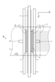
- FIG. 1 is a schematic perspective view of a first coating device of the present invention.
- FIG. 2 is a sectional view taken along an XZ plane outside the side plate of the coating device shown in FIG. 1;
- FIG. 2 is a top view of the coating apparatus of FIG. 1;
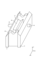
- FIG. 2 is a schematic perspective view of the coating device of FIG. 1 with a coating bar removed.
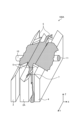
- It is a schematic perspective view of the second coating device of this invention. It is a diagram illustrating a state in which a coating liquid is supplied to a second coating device of the present invention, and the coating bar is omitted from the illustration.
- It is a sectional view of the XZ plane outside the side plate of the conventional coating device.
- FIG. 2 is a cross-sectional view of the coating device taken along the XZ plane, illustrating the coating process when the coating liquid supplied to the upstream container is insufficient.
- FIG. 3 is a cross-sectional view of the coating device taken along the XZ plane, illustrating the coating process when the coating liquid supplied to the downstream container is insufficient.
- FIG. 3 is a schematic perspective view of the coating device of Patent Document 4 with the coating bar removed.
- FIG. 1 is a schematic perspective view of the first coating device
- FIG. 2 is a cross-sectional view of the first coating device on the XZ plane
- FIG. 3 is a top view of the first coating device in the XY plane looking down from vertically above.
- the first coating device 100 includes a coating bar 1 extending in the web width direction with respect to the web 9, and a partition member disposed vertically below the axial center of the coating bar 1 and extending in the web width direction. 2.
- An upstream main plate 3 and a downstream main plate 4 arranged parallel to each other on the upstream and downstream sides of the web conveyance direction with the partition member 2 in between, the inner side in the web width direction of both ends of the partition member 2 in the web width direction It is provided so as to be in contact with the side plate 5, the partition member 2, the upstream main plate 3, the downstream main plate 4, and the side plate 5, which are arranged on the upstream side.
- a bottom plate (not shown) forming the container 20 and the downstream container 21 is provided.
- the coating liquid 12 is supplied to the upstream container 20 and the downstream container 21 from the upstream container coating liquid supply port 10 and the downstream container coating liquid supply port 11, respectively.
- the width L2 between the two side plates 5 is the width over which the coating liquid is applied to the web 9, that is, the width set as the desired coating width.
- the side plate 5 may be slidable in the web width direction, and in that case, the sliding range of the side plate 5 becomes the adjustment margin for the coating width.
- FIG. 4 is a schematic perspective view of the first coating device with the coating bar removed.
- the partition member 2 is a plate-shaped member, and a V-shaped support portion 2a is formed on the side that supports the coating bar 1, and the coating bar 1 is supported by the support portion 2a.
- the support portion 2a is V-shaped, but may be arc-shaped as long as it can support the coating bar 1.
- the support portion 2a of the partition member 2 is formed with an inclined surface 6 for discharging the coating liquid from a position within the range of the web width L1 of the web 9 to be coated and outside the side plate 5 in the web width direction. ing.
- the inclined surface 6 is formed by cutting out the downstream surface of the support section 2a, and functions as a flow path through which the coating liquid flows out from between the coating bar 1 and the support section 2a.
- the inclined surface 6 is formed to be inclined vertically downward from a position vertically below the coating bar 1 toward the downstream side in the web conveyance direction.
- the inclined surface 6 may be a flat surface that slopes vertically downward toward the upstream side in the web conveyance direction, as long as it can discharge the coating liquid from between the coating bar 1 and the partition member 2.
- both ends of the partition member 2 are all sloped surfaces, but the sloped surface 6 is provided only around the side plate 5, and the support portion 2a remains as it is without forming the sloped surface 6 on the end side. You can also use it as
- the coating bar 1 for example, a wire bar with grooves formed by winding wire on the outer circumferential surface of the bar, a rolled bar with grooves formed on the outer circumferential surface of the bar by rolling processing, a small-diameter gravure roll, etc. can be used. can.
- the material of the coating bar 1 is preferably stainless steel, particularly SUS304 or SUS316.
- the surface of the coating bar 1 may be subjected to surface treatment such as hard chrome plating. If the diameter of the coating bar 1 is too large, streak-like coating defects along the conveyance direction called rib streaks are likely to occur, and if it is too small, the deflection of the coating bar 1 will become large. is preferably 4 to 20 mm.
- the coating bar may be rotated in a so-called driven rotation state in which the coating bar 1 is pressed against the web 9 and rotated by the frictional force with the web 9, or may be rotated by a drive device such as a motor.
- a drive device When rotated by a drive device, it is preferable that the coating bar 1 be rotated in the transport direction of the web 9 at substantially the same speed as the transport speed of the web 9 in order to prevent the web 9 from being damaged.
- substantially the same speed means that the speed difference between the circumferential speed of the coating bar 1 and the conveyance speed of the web 9 is within a range of ⁇ 10%.
- the coating bar 1 may be rotated at a speed different from the transport speed of the web 9 or in a direction opposite to the transport direction.
- the side plate 5 has a gap of 0.3 mm between each component in order to prevent the coating liquid from leaking outside the coating width, to improve the sealing of the container as much as possible, and to not impair sliding properties. It is preferable to do the following.
- the material is not particularly limited, but a resin material with high sliding properties is preferred.
- the means for sliding the side plate 5 in the width direction may be a motor, an air cylinder, or manually. By making the side plate 5 slidable without disassembling the device, the coating width can be easily adjusted when changing production types.
- the partition member 2 is installed to partition the flow path of the coating liquid supplied to the upstream side and the downstream side with respect to the web conveyance direction of the coating bar 1.
- its shape is not particularly limited, and it does not need to be in contact with the coating bar 1 as long as it is sufficiently close to it. It is preferable that the gap between the parts closest to the coating bar is 1 mm or less.
- FIG. 5 is a schematic perspective view of a second coating apparatus 100A of the present invention.
- the support portion 2a of the partition member 2A is provided with a flow path for discharging the coating liquid, the bottom of which extends vertically downward from a position vertically below the coating bar 1 toward the downstream side in the web conveyance direction.
- Four grooves 7 are provided which are inclined to the side. It is sufficient that at least one groove 7 is provided within the range of the web width of the partition member 2A and outside of the side plate 5 in the web width direction, and within the range of the web width of the partition member 2A and outside of the side plate 5 in the web width direction. It is preferable to provide them at both outer ends in the width direction.
- the reason why four grooves 7 are provided in the second coating device 100A is to accommodate changes in web width, and four or more grooves 7 may be provided.
- the bottom surface of the groove 7 may be inclined vertically downward toward the upstream side in the web conveyance direction.
- the size of the groove 7 is preferably determined depending on the flow rate of the coating liquid to be discharged.
- the shape of the cross section of the groove 7 in the web width direction is not particularly limited as long as it satisfies the discharge function, such as a rectangular or elliptical shape. If there is a part where the coating bar 1 is not supported in the range where the coating width is adjusted, if the coating width adjustment range is significantly widened, the deflection of the coating bar 1 at that part will increase, which will affect the coating quality.
- the partition member 2A directly contacts and supports the coating bar 1 from below over the entire coating width, the coating bar 1 is supported in the portion where the groove 7 is formed.
- the coating bar 1 is not supported locally and does not have a large effect on the deflection of the coating bar 1. Therefore, even within the range in which the coating width can be adjusted, stable coating can be achieved without degrading the coating quality, and the range in which the coating width can be adjusted is dramatically expanded.
- FIG. 6 is a diagram illustrating how the coating liquid 12 is being supplied to the second coating device 100A, and the coating bar 1 is omitted from the illustration.
- the coating liquid 12 supplied from the upstream container coating liquid supply port 10 and the downstream container coating liquid supply port 11 accumulates in the upstream container 20 and the downstream container 21, and is transmitted from the upper surface of the partition member 2A to the support portion 2a.
- the web spreads toward both ends in the web width direction. Since the support part 2a of the partition member 2A has a groove 7 on the outer side in the web width direction than the side plate 5, the coating liquid is discharged from the groove 7 to the outside of each container, and the coating liquid is on the upper surface of the partition member 2A. It never accumulates.
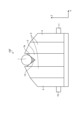
- FIG. 7 is a cross-sectional view of the conventional coating apparatus 100' taken along the XZ plane at the end in the width direction.
- FIG. 8 is a diagram illustrating a state in which a coating liquid is supplied to a conventional coating apparatus 100', and the coating bar 1 is omitted from the illustration.
- the support portion 2a of the partition member 2' that supports the coating bar 1 extends across the entire width of the web with the same cross section.
- the coating liquid In order to support the coating bar 1, it is necessary to contact the partition member 2' from below, but since the coating bar 1 has a cylindrical shape, a commonly used partition having a V-shaped support part 2a is used.
- the coating liquid accumulates in the gap 13 between the coating bar 1 and the support portion 2a provided on the partition member 2'.
- the coating liquid spreads in the width direction along this gap 13 and is not discharged, so that the coating liquid spreads to the outside of the side plate 5 and the coating bar 1 becomes wet, as shown in FIG. That is, the coating liquid is applied to the web even outside the side plate 5, and no uncoated portions can be formed.
- FIG. 9 is a schematic perspective view of a third coating apparatus 100B of the present invention.
- the third coating device 100B serves as a flow path for discharging the coating liquid, and extends from a position vertically below the coating bar 1 through the interior of the partition member 2B to a downstream side of the partition member 2B in the web conveyance direction. It has four holes 8 extending to the sides. It is sufficient that at least one hole 8 is provided within the range of the web width of the partition member 2B and outside of the side plate 5 in the web width direction; It is preferable to provide them at both outer ends in the width direction.
- the reason why the four holes 8 are provided in the third coating device 100B is to accommodate changes in the web width, and four or more holes 8 may be provided.
- the hole 8 may penetrate through the inside of the partition member 2B and reach the upstream side surface of the partition member 2 in the web conveyance direction.
- the cross-sectional shape of the hole 8 is not limited to a circular, oval, or rectangular shape, and its size is determined depending on the flow rate of the coating liquid used.
- the partition member 2B directly contacts and supports the coating bar 1 from below, and can support the coating bar 1 even within the range where the hole 8 is formed. 1, and stable coating can be performed without degrading the coating quality even within the range where the coating width is adjusted.
- FIG. 10 is a schematic perspective view of a fourth coating apparatus 100C of the present invention.
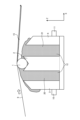
- FIG. 11 is a cross-sectional view on the XZ plane of a portion of the fourth coating device 100C where the support body 14 is present.
- FIG. 12 is a schematic perspective view of the partition member 2C in a portion where the support body 14 is present.
- the fourth coating apparatus 100C includes partition members extending in the web width direction, while supports 14 that support the coating bar 1 from below are arranged at intervals in the web width direction.
- 2C is a coating device arranged vertically below the axial center of the coating bar 1. As shown in FIG.
- the partition member 2 extending in the web width direction separates the coating bar 1 from the upstream side and the downstream side vertically below the axial center of the coating bar 1. It is partitioned on the side.
- the flow path for discharging the coating liquid is formed by passing through the inside of the partition member 2 from a position vertically below the coating bar 1 at a location where the support 14 is not present in the web width direction.
- a form having an inclined surface 6C vertically downward is shown.
- FIG. 12 shows an embodiment in which the support body 14 is a roller. The outer periphery of the roller of the support body 14 is in contact with the coating bar 1, and since it rotates together with the coating bar 1 about the shaft 22 attached to the partition member 2C as the rotation axis, the coating bar 1 and the support body 14 are not worn.
- support by rollers is shown in FIGS. 10, 11, and 12 as the support 14, it may be a V-shaped support, an arc-shaped support, or a support that supports the coating bar 1 while rotating.
- the form is not limited as long as it can support the coating bar 1, such as a ball.
- the material of the support body 14 in order to reduce wear of the coating bar 1, it is preferable to use a material whose hardness is lower than that of the coating bar 1 for the surface layer of the support body.
- the spacing between the supports 14 arranged along the longitudinal direction of the coating bar 1 is preferably narrow, since if the spacing is too wide, the deflection of the coating bar 1 will increase.
- As a guideline it is preferable to arrange the coating bar 1 so that its deflection is 10 ⁇ m or less.
- the amount of deflection is calculated by applying the reaction force in the out-of-plane direction of the web 9 calculated from the tension applied to the running direction of the web 9 as a uniformly distributed load applied to the coating bar 1, using the support 14 as a support point, and applying the reaction force in the out-of-plane direction of the web 9 to the coating bar It can be determined from a material mechanics formula using a moment of inertia of 1 and Young's modulus.
- the coating bar 1 is contacted and supported from below by the support 14, so that the deflection of the coating bar 1 can be suppressed and the coating quality can be improved. Can be applied stably without dropping.
- the support 14 may be provided within the range of the inclined surface 6 of the partition member 2 as well.
- Examples of the material for the support 14 include metals such as iron, stainless steel, aluminum, and copper, nylon, acrylic resin, vinyl chloride resin, synthetic resins such as tetrafluoroethylene, and rubber. Moreover, the shape may be plate-like or block-like.
- Coating method A method of coating a web using the first to fourth coating devices 100, 100A, 100B and 100C will be described.
- Coating liquid 12 is supplied from upstream container coating liquid supply port 10 and downstream container coating liquid supply port 11 to upstream container 20 and downstream container 21, respectively. Coating is performed on the conveyed web 9 by raising the coating device and pressing the coating bar 1 against the lower surface of the web 9 from below.
- the angle at which the web 9 wraps the coating bar 1 is not particularly limited, it is more preferably 0 degrees or more and 20 degrees or less.
- the coating liquid supply means gear pumps, diaphragm pumps, and Mono pumps having quantitative properties and low pulsation properties are preferable.
- the coating liquid 12 discharged from the pump may be supplied to the container via a filter or defoaming means.
- the coating liquid supplied from the coating liquid tank to the container via the pump and the supply port is circulated to the coating liquid tank via the flow paths of the coating apparatuses 100, 100A, 100B, and 100C.
- FIG. 13 is a diagram illustrating a situation when the coating liquid 12 supplied to the upstream container 20 is insufficient
- FIG. 14 is a diagram illustrating a situation when the coating liquid 12 supplied to the downstream container 21 is insufficient.
- FIG. 3 is a diagram illustrating the situation, and both are cross-sectional views of the coating device on the XZ plane.
- the partition member 2 and are generated as air bubbles 15 on the upstream side of the coating bar 1, and then pass between the web 9 and the coating bar 1, and the air bubbles 15 are mixed into the coating film. Put it away. If the air bubbles 15 are mixed into the coating film as described above, defects such as coating omissions due to the air bubbles will occur. Alternatively, if the air bubbles 15 continue to remain between the web 9 and the coating bar 1, a streak-like defect occurs. On the other hand, if the supplied flow rate is too large, problems such as an increase in foreign matter and air bubbles passing through the filter occur.
- the balance between the flow rate of the coating liquid 12 supplied to the upstream container 20 and the flow rate of the coating liquid 12 supplied to the downstream container 21 is adjusted to minimize air bubbles. It is preferable to set the flow rate so that this does not occur.
- the coating liquid 12 supplied to the upstream container 20 and the downstream container 21 is preferably adjusted according to coating conditions such as the thickness of the coating film, the conveyance speed of the web 9, and the rotation speed of the coating bar 1. Further, the web targeted by this coating method is not particularly limited as long as it is in the form of a long sheet such as paper, film, or metal foil.
- the viscosity of the coating liquid 12 used in the coating apparatus according to this embodiment is preferably 0.1 Pa ⁇ s or less. When the viscosity of the coating liquid 12 is high, a living phenomenon may occur and coating streaks may occur.
- the coating amount of the coating liquid 12 is preferably 100 g/m 2 or less in a wet state immediately after coating. Generally, in the bar coating method, the coating quality is better when the coating weight is low, so the coating weight is preferably in the range of 4 to 50 g/m 2 .
- the amount of coating can be adjusted by adjusting the size of the groove formed in the coating bar 1.
- the size of the groove can be determined by changing the wire diameter of the wire to be wound if the coating bar 1 is a wire bar, or by rolling with a die with a different groove depth and/or groove pitch if the coating bar 1 is a rolling bar. It can be changed by processing.
- PET polyethylene terephthalate
- an intrinsic viscosity also called intrinsic viscosity
- 0.62 dl/g measured in o-chlorophenol at 25°C according to the standard of JIS K7367-5 (2000 edition)
- this unstretched film was heated with a group of rolls heated to 80°C, further stretched by a factor of 3.2 in the longitudinal direction while being heated with an infrared heater, and then stretched with cooling rolls adjusted to 50°C. It was cooled to form a uniaxially stretched resin film.
- the width of the resin film was 1700 mm.
- the coating liquid 12 was applied to the lower surface of this resin film traveling at a speed of 200 m/min.
- the resin film coated with the coating liquid 12 is guided into an oven at 90°C and heated, and then the coating liquid 12 is dried in an oven at 100°C, and the resin film is stretched in the width direction.
- the resin film was stretched by 3.7 times and then heat-set while being subjected to a relaxation treatment of 5% in the width direction in an oven at 220°C. In this way, a biaxially stretched film having a film formed with the coating liquid 12 on one side was obtained.
- the tension between the longitudinal stretching machine and the transverse stretching machine was controlled by a dancer roll so that the tension per unit width in the running direction of the resin film was 8000 N/m.
- Coating liquid 12 is an emulsion of a polyester copolymer (components: 90 mol% terephthalic acid, 10 mol% 5-sodium sulfoisophthalic acid, solvent: 96 mol% ethylene glycol, 3 mol% neopentyl glycol, 1 mol% diethylene glycol).
- a polyester copolymer components: 90 mol% terephthalic acid, 10 mol% 5-sodium sulfoisophthalic acid, solvent: 96 mol% ethylene glycol, 3 mol% neopentyl glycol, 1 mol% diethylene glycol.
- a melamine crosslinking agent manufactured by Nippon Carbide Kogyo Co., Ltd.: MW-390
- colloidal silica particles having an average particle size of 0.1 ⁇ m were added to prepare a mixed solution.
- This coating liquid 12 was 2 mPa ⁇ s at a temperature of 25°C.
- This coating liquid is applied to the upstream container coating liquid supply port 10 and the downstream container coating liquid supply port 11 of the first coating device 100 in FIG. It was supplied to the upstream container 20 and the downstream container 21.
- As the coating bar 1 a stainless steel round bar with a diameter of 12.7 mm and a length of 2000 mm was wound with a wire having a linear diameter of 0.1 mm (manufactured by Kano Shoji Co., Ltd.).
- the side plates 5 were arranged so that the side plate interval L2 was 1600 mm (L3: 1000 mm).
- the first coating device 100 coating was carried out while pressing the coating bar 1 against the conveyed web 9 and rotating the coating bar 1 in a driven manner.
- the coating bar 1 was supported by a V-shaped support portion 2a of the partition member 2.
- the partition member 2 has a V-shaped sloped surface 6 with the downstream side cut off in the coating adjustment width (300 mm on each side).
- the coating results are shown in Table 1. With respect to the side plate spacing L2 (1600 mm), the width of the coating on the web was L2+8 mm, and it was confirmed that the film could be formed without any problems.
- the coating bar 1 was removed once, and the coating liquid was continued to flow at a rate of 50 L/min for 3 minutes, and then the coating bar 1 was removed again. I attached it and applied the coating, but I was able to form the uncoated areas without any problems.
- the supply rate of the coating liquid without bubbles from both the upstream side and the downstream side was 10 L/min on the upstream side and 27 L/min on the downstream side.
- Example 2 Using the second coating device 100A, the coating bar 1 was supported over its entire width by the V-shaped support portion 2a of the partition member 2A, as shown in FIG. Regarding the coating adjustment width of the partition member 2A, a V-shaped support portion 2a having grooves 7 intermittently dug in the web width direction was used. The grooves 7 had a width of 10 mm and a depth of 20 mm, and the center distance between the grooves in the web width direction was 140 mm. Coating was carried out in the same manner as in Example 1 except for this. The coating results are shown in Table 1.
- the width coated on the web was L2+10 mm, and it was confirmed that the film could be formed without any problems. Further, in the same manner as in Example 1, even if the coating liquid was continued to flow for 3 minutes at a supply rate of 50 L/min and then coated again, a non-coated portion could be formed.
- the supply rate of the coating liquid without any bubbles from both the upstream side and the downstream side was 10 L/min on the upstream side and 25 L/min on the downstream side.
- Example 3 Using the third coating device 100B, the coating bar 1 was supported over its entire width by the V-shaped support portion 2a of the partition member 2B, as shown in FIG. Regarding the coating adjustment width of the partition member 2B, a V-shaped support portion 2a having holes 8 disposed intermittently in the web width direction was used. The hole 8 had a diameter of 8 mm and communicated with the outside of the partition member 2B at a position 10 mm downward in the Z direction. The center distance between the holes in the web width direction was 142 mm. Coating was carried out in the same manner as in Example 1 except for this. The coating results are shown in Table 1.
- the width coated on the web was L2+11 mm, and it was confirmed that the film could be formed without any problems. Further, in the same manner as in Example 1, even if the coating liquid was continued to flow for 3 minutes at a supply rate of 50 L/min and then coated again, a non-coated portion could be formed.
- the supply rate of the coating liquid without any bubbles from both the upstream side and the downstream side was 10 L/min on the upstream side and 25 L/min on the downstream side.
- the coating bar 1 was supported by rollers (supports 14) arranged intermittently in the web width direction, as shown in FIG.
- the holes 8 are arranged intermittently in the width direction of the web in the part where the support 14 is not present, and the coating bar 1 is in the shape where the holes 8 are arranged intermittently in the web width direction in the part where the support 14 is present.
- a shape having an inclined surface 6C that is inclined vertically downward by 5 degrees toward the downstream side in the web conveyance direction from a vertically downward position was applied.
- the hole 8 had a diameter of 8 mm and communicated with the outside of the partition member 2B at a position 10 mm downward in the Z direction.
- the center distance between the holes in the web width direction was 192 mm.
- Coating was carried out in the same manner as in Example 1 except for this.
- the coating results are shown in Table 1.
- the width coated on the web was L2+8 mm, and it was confirmed that the film could be formed without any problems.
- the supply rate of the coating liquid without bubbles from both the upstream side and the downstream side was 10 L/min on the upstream side and 28 L/min on the downstream side.
- Example 1 A coating device similar to Example 1 except that a partition plate having a V-shaped support portion 2a formed over the entire width is used, and the outside of the side plate is a V-shaped block (no flow path) with the same cross section. Coating was carried out under the same conditions. The coating results are shown in Table 1. With respect to the width L2 (1600 mm) between the side plates regulated by the side plates, the width coated on the web exceeded L2+30 mm, and the entire width of the web was coated. Thereafter, in the transverse stretching step, both ends of the web in the width direction were held with clips, but because the coating liquid was present between the clips and the web, the clips slipped and came off, making it impossible to stretch.
- Example 2 Further, in the same manner as in Example 1, after the coating liquid was continued to flow for 3 minutes at a supply rate of 50 L/min, coating was performed again, but no uncoated portion could be formed.
- the supply rate of the coating liquid without any bubbles from both the upstream side and the downstream side was 11 L/min on the upstream side and 25 L/min on the downstream side.
- FIG. 15 shows the coating apparatus described in Patent Document 4, with the coating bar removed.
- a container 17 is constructed by arranging a side plate 18 at the end of the coating device in the web width direction.
- the partition member 16 has a V-shaped support portion.
- the partition member 16 has a length of 1250 mm in the web width direction, and when the coating width is adjusted to be wider than 1250 mm by sliding the side plate 18 outward in the web width direction, the side plate 18 at the end in the web width direction becomes a partition.
- the upstream and downstream containers are spaced apart from the member 16 and communicate with each other.
- Example 1 coating was carried out in the same manner as in Example 1, except that the coating width was adjusted to be wide so that the partition member 16 and the side plate 18 were separated from each other.
- the coating results are shown in Table 1. With respect to the width L2 (1600 mm) between the side plates regulated by the side plates 18, the width coated on the web was L2+11 mm, and it was confirmed that the film could be formed without any problems. Further, as in Example 1, even if the coating liquid was continued to flow for 3 minutes at a supply rate of 50 L/min and then coated again, a non-coated portion could be formed. The supply rate of the coating liquid without bubbles from both the upstream side and the downstream side was 20 L/min on the upstream side and 32 L/min on the downstream side.
- Controllability of coating fluid supply amount In order to prevent bubbles from being trapped during coating, it is better to have a large total of the upstream and downstream coating liquid supply amounts, but this poses the problem of increasing the capacity of the coating liquid supply pump. This may cause problems such as an increase in the amount of foreign matter passing through the filter. It is better to keep the total amount of coating liquid supplied as low as possible while preventing bubbles from being trapped during coating. Therefore, judging from the applicant's past coating experience, the controllability of the coating liquid supply amount was evaluated based on the following criteria. ⁇ (Good): The total supply amount of the coating liquid is 50 L/min or less. ⁇ (Poor): The total supply amount of the coating liquid exceeds 50 L/min.
- the coating device of the present invention can be used to coat a coating liquid onto a web-like object such as a film, paper, or metal foil.
Landscapes
- Coating Apparatus (AREA)
- Application Of Or Painting With Fluid Materials (AREA)
- Life Sciences & Earth Sciences (AREA)
- Engineering & Computer Science (AREA)
- Wood Science & Technology (AREA)
Priority Applications (5)
| Application Number | Priority Date | Filing Date | Title |
|---|---|---|---|
| CN202380025049.XA CN118829488A (zh) | 2022-03-15 | 2023-02-07 | 涂布装置及带涂膜的网的制造方法 |
| KR1020247028689A KR20240159572A (ko) | 2022-03-15 | 2023-02-07 | 도포 장치 및 도막이 부착된 웹의 제조 방법 |
| JP2023516616A JPWO2023176200A1 (https=) | 2022-03-15 | 2023-02-07 | |
| EP23770161.0A EP4494767A4 (en) | 2022-03-15 | 2023-02-07 | COATING DEVICE AND METHOD FOR MANUFACTURING A VEIL WITH A COATING FILM |
| US18/842,187 US20250178016A1 (en) | 2022-03-15 | 2023-02-07 | Coating device and method for producing web with coating film |
Applications Claiming Priority (2)
| Application Number | Priority Date | Filing Date | Title |
|---|---|---|---|
| JP2022-039893 | 2022-03-15 | ||
| JP2022039893 | 2022-03-15 |
Publications (1)
| Publication Number | Publication Date |
|---|---|
| WO2023176200A1 true WO2023176200A1 (ja) | 2023-09-21 |
Family
ID=88022779
Family Applications (1)
| Application Number | Title | Priority Date | Filing Date |
|---|---|---|---|
| PCT/JP2023/004046 Ceased WO2023176200A1 (ja) | 2022-03-15 | 2023-02-07 | 塗工装置および塗膜付きウェブの製造方法 |
Country Status (6)
| Country | Link |
|---|---|
| US (1) | US20250178016A1 (https=) |
| EP (1) | EP4494767A4 (https=) |
| JP (1) | JPWO2023176200A1 (https=) |
| KR (1) | KR20240159572A (https=) |
| CN (1) | CN118829488A (https=) |
| WO (1) | WO2023176200A1 (https=) |
Citations (7)
| Publication number | Priority date | Publication date | Assignee | Title |
|---|---|---|---|---|
| JP2003251256A (ja) * | 2002-03-06 | 2003-09-09 | Fuji Photo Film Co Ltd | 塗布装置および塗布方法 |
| JP2004074147A (ja) | 2002-06-12 | 2004-03-11 | Fuji Photo Film Co Ltd | 塗布装置および塗布方法 |
| JP2006082059A (ja) * | 2004-09-17 | 2006-03-30 | Fuji Photo Film Co Ltd | バー塗布方法及び装置 |
| JP2007326080A (ja) | 2006-06-09 | 2007-12-20 | Fujifilm Corp | ロッド塗布方法及び装置 |
| JP2009160552A (ja) | 2008-01-09 | 2009-07-23 | Nitto Denko Corp | 塗布装置及び積層シート |
| JP2013034980A (ja) * | 2011-08-11 | 2013-02-21 | Hirano Tecseed Co Ltd | 塗工装置 |
| JP2020000961A (ja) | 2018-06-25 | 2020-01-09 | 住友化学株式会社 | 液体塗布装置 |
Family Cites Families (4)
| Publication number | Priority date | Publication date | Assignee | Title |
|---|---|---|---|---|
| EP1293261A3 (en) * | 2001-09-13 | 2005-02-02 | Fuji Photo Film Co., Ltd. | Bar coating apparatus and bar coating method |
| US7048969B2 (en) * | 2001-09-28 | 2006-05-23 | Fuji Photo Film Co., Ltd. | Coating device and coating method |
| US7354479B2 (en) * | 2002-06-12 | 2008-04-08 | Fujifilm Corporation | Coating device, and coating method using said device |
| KR102306424B1 (ko) * | 2019-02-13 | 2021-09-28 | 삼성에스디아이 주식회사 | 분리막 코팅 장치 |
-
2023
- 2023-02-07 WO PCT/JP2023/004046 patent/WO2023176200A1/ja not_active Ceased
- 2023-02-07 KR KR1020247028689A patent/KR20240159572A/ko active Pending
- 2023-02-07 EP EP23770161.0A patent/EP4494767A4/en active Pending
- 2023-02-07 US US18/842,187 patent/US20250178016A1/en active Pending
- 2023-02-07 JP JP2023516616A patent/JPWO2023176200A1/ja active Pending
- 2023-02-07 CN CN202380025049.XA patent/CN118829488A/zh active Pending
Patent Citations (7)
| Publication number | Priority date | Publication date | Assignee | Title |
|---|---|---|---|---|
| JP2003251256A (ja) * | 2002-03-06 | 2003-09-09 | Fuji Photo Film Co Ltd | 塗布装置および塗布方法 |
| JP2004074147A (ja) | 2002-06-12 | 2004-03-11 | Fuji Photo Film Co Ltd | 塗布装置および塗布方法 |
| JP2006082059A (ja) * | 2004-09-17 | 2006-03-30 | Fuji Photo Film Co Ltd | バー塗布方法及び装置 |
| JP2007326080A (ja) | 2006-06-09 | 2007-12-20 | Fujifilm Corp | ロッド塗布方法及び装置 |
| JP2009160552A (ja) | 2008-01-09 | 2009-07-23 | Nitto Denko Corp | 塗布装置及び積層シート |
| JP2013034980A (ja) * | 2011-08-11 | 2013-02-21 | Hirano Tecseed Co Ltd | 塗工装置 |
| JP2020000961A (ja) | 2018-06-25 | 2020-01-09 | 住友化学株式会社 | 液体塗布装置 |
Non-Patent Citations (1)
| Title |
|---|
| See also references of EP4494767A4 |
Also Published As
| Publication number | Publication date |
|---|---|
| US20250178016A1 (en) | 2025-06-05 |
| CN118829488A (zh) | 2024-10-22 |
| EP4494767A1 (en) | 2025-01-22 |
| JPWO2023176200A1 (https=) | 2023-09-21 |
| EP4494767A4 (en) | 2026-03-18 |
| KR20240159572A (ko) | 2024-11-05 |
Similar Documents
| Publication | Publication Date | Title |
|---|---|---|
| JPS629381B2 (https=) | ||
| CN106794484B (zh) | 浆液涂覆装置以及浆液涂覆方法 | |
| TW200822977A (en) | Coating method and coating device | |
| CN1672805B (zh) | 涂层设备和涂层方法 | |
| US8733275B2 (en) | Application apparatus, application method and method for manufacturing web having coating film | |
| KR20080087753A (ko) | 웹 안내 롤러, 웹 안내 장치 및 웹 안내 방법 | |
| JPH044071A (ja) | 塗布方法 | |
| JP4760271B2 (ja) | 塗工・乾燥装置及び塗工・乾燥方法 | |
| US20090263626A1 (en) | Die coating apparatus, die coating method, and adhesive sheet and foamed sheet | |
| WO2023176200A1 (ja) | 塗工装置および塗膜付きウェブの製造方法 | |
| JP6387830B2 (ja) | 塗布装置、塗布方法および塗膜つき樹脂フィルムの製造方法 | |
| US20090151626A1 (en) | Coating apparatus | |
| KR101778837B1 (ko) | 기재에의 도포 방법 | |
| US20090133618A1 (en) | Coating apparatus | |
| JPH06254466A (ja) | 塗布装置 | |
| CN116600905B (zh) | 多层膜的制造方法及涂布装置 | |
| JP5062125B2 (ja) | 塗布方法および塗布装置 | |
| JP4743482B2 (ja) | 塗布液の塗布方法、および塗布装置 | |
| JP2002331267A (ja) | 塗布膜の乾燥方法 | |
| JP2005296699A (ja) | バー塗布方法及び装置 | |
| CN116529188A (zh) | 多层膜的制造方法 | |
| EP4084913A1 (en) | Die coating on air supported shell | |
| JPH11216411A (ja) | 塗布方法及び塗布装置 | |
| JPH0838995A (ja) | 凹凸表面層を有するウエッブ送り用ロールの製造方法および凹凸表面層を有するウエッブ送り用ロール | |
| JP2000312850A (ja) | ウェブへの塗布装置およびそれを用いた塗布方法 |
Legal Events
| Date | Code | Title | Description |
|---|---|---|---|
| WWE | Wipo information: entry into national phase |
Ref document number: 2023516616 Country of ref document: JP |
|
| 121 | Ep: the epo has been informed by wipo that ep was designated in this application |
Ref document number: 23770161 Country of ref document: EP Kind code of ref document: A1 |
|
| WWE | Wipo information: entry into national phase |
Ref document number: 18842187 Country of ref document: US |
|
| WWE | Wipo information: entry into national phase |
Ref document number: 202380025049.X Country of ref document: CN |
|
| WWE | Wipo information: entry into national phase |
Ref document number: 2023770161 Country of ref document: EP |
|
| NENP | Non-entry into the national phase |
Ref country code: DE |
|
| ENP | Entry into the national phase |
Ref document number: 2023770161 Country of ref document: EP Effective date: 20241015 |
|
| WWP | Wipo information: published in national office |
Ref document number: 18842187 Country of ref document: US |