WO2023176200A1 - Coating device and method for manufacturing web equipped with coating film - Google Patents
Coating device and method for manufacturing web equipped with coating film Download PDFInfo
- Publication number
- WO2023176200A1 WO2023176200A1 PCT/JP2023/004046 JP2023004046W WO2023176200A1 WO 2023176200 A1 WO2023176200 A1 WO 2023176200A1 JP 2023004046 W JP2023004046 W JP 2023004046W WO 2023176200 A1 WO2023176200 A1 WO 2023176200A1
- Authority
- WO
- WIPO (PCT)
- Prior art keywords
- coating
- web
- bar
- coating liquid
- width direction
- Prior art date
Links
- 238000000576 coating method Methods 0.000 title claims abstract description 459
- 239000011248 coating agent Substances 0.000 title claims abstract description 449
- 238000004519 manufacturing process Methods 0.000 title claims description 6
- 238000000034 method Methods 0.000 title description 13
- 239000007788 liquid Substances 0.000 claims abstract description 136
- 238000011144 upstream manufacturing Methods 0.000 claims abstract description 78
- 238000005192 partition Methods 0.000 claims description 73
- 238000007599 discharging Methods 0.000 claims description 11
- 238000003825 pressing Methods 0.000 claims description 4
- 238000000638 solvent extraction Methods 0.000 abstract 4
- 230000003247 decreasing effect Effects 0.000 abstract 1
- 229920005989 resin Polymers 0.000 description 9
- 239000011347 resin Substances 0.000 description 9
- 238000010586 diagram Methods 0.000 description 7
- 239000000463 material Substances 0.000 description 7
- 230000001105 regulatory effect Effects 0.000 description 5
- 238000007611 bar coating method Methods 0.000 description 4
- 230000007547 defect Effects 0.000 description 4
- 238000011156 evaluation Methods 0.000 description 4
- LYCAIKOWRPUZTN-UHFFFAOYSA-N Ethylene glycol Chemical compound OCCO LYCAIKOWRPUZTN-UHFFFAOYSA-N 0.000 description 3
- 230000000052 comparative effect Effects 0.000 description 3
- 230000000593 degrading effect Effects 0.000 description 3
- MTHSVFCYNBDYFN-UHFFFAOYSA-N diethylene glycol Chemical compound OCCOCCO MTHSVFCYNBDYFN-UHFFFAOYSA-N 0.000 description 3
- 229910052751 metal Inorganic materials 0.000 description 3
- 239000002184 metal Substances 0.000 description 3
- 238000005096 rolling process Methods 0.000 description 3
- 229910001220 stainless steel Inorganic materials 0.000 description 3
- 239000010935 stainless steel Substances 0.000 description 3
- XEEYBQQBJWHFJM-UHFFFAOYSA-N Iron Chemical compound [Fe] XEEYBQQBJWHFJM-UHFFFAOYSA-N 0.000 description 2
- KKEYFWRCBNTPAC-UHFFFAOYSA-N Terephthalic acid Chemical compound OC(=O)C1=CC=C(C(O)=O)C=C1 KKEYFWRCBNTPAC-UHFFFAOYSA-N 0.000 description 2
- 239000011888 foil Substances 0.000 description 2
- 239000002245 particle Substances 0.000 description 2
- 229920000139 polyethylene terephthalate Polymers 0.000 description 2
- 239000005020 polyethylene terephthalate Substances 0.000 description 2
- 238000004804 winding Methods 0.000 description 2
- ISPYQTSUDJAMAB-UHFFFAOYSA-N 2-chlorophenol Chemical compound OC1=CC=CC=C1Cl ISPYQTSUDJAMAB-UHFFFAOYSA-N 0.000 description 1
- 229920000178 Acrylic resin Polymers 0.000 description 1
- 239000004925 Acrylic resin Substances 0.000 description 1
- 229920002799 BoPET Polymers 0.000 description 1
- VYZAMTAEIAYCRO-UHFFFAOYSA-N Chromium Chemical compound [Cr] VYZAMTAEIAYCRO-UHFFFAOYSA-N 0.000 description 1
- RYGMFSIKBFXOCR-UHFFFAOYSA-N Copper Chemical compound [Cu] RYGMFSIKBFXOCR-UHFFFAOYSA-N 0.000 description 1
- 229920000877 Melamine resin Polymers 0.000 description 1
- 239000004677 Nylon Substances 0.000 description 1
- VYPSYNLAJGMNEJ-UHFFFAOYSA-N Silicium dioxide Chemical compound O=[Si]=O VYPSYNLAJGMNEJ-UHFFFAOYSA-N 0.000 description 1
- BZHJMEDXRYGGRV-UHFFFAOYSA-N Vinyl chloride Chemical compound ClC=C BZHJMEDXRYGGRV-UHFFFAOYSA-N 0.000 description 1
- 230000002411 adverse Effects 0.000 description 1
- 229910052782 aluminium Inorganic materials 0.000 description 1
- XAGFODPZIPBFFR-UHFFFAOYSA-N aluminium Chemical compound [Al] XAGFODPZIPBFFR-UHFFFAOYSA-N 0.000 description 1
- 230000015572 biosynthetic process Effects 0.000 description 1
- 238000005266 casting Methods 0.000 description 1
- 239000008119 colloidal silica Substances 0.000 description 1
- 238000001816 cooling Methods 0.000 description 1
- 229910052802 copper Inorganic materials 0.000 description 1
- 239000010949 copper Substances 0.000 description 1
- 239000003431 cross linking reagent Substances 0.000 description 1
- 238000005520 cutting process Methods 0.000 description 1
- 230000002542 deteriorative effect Effects 0.000 description 1
- 230000000694 effects Effects 0.000 description 1
- 239000000839 emulsion Substances 0.000 description 1
- 239000012530 fluid Substances 0.000 description 1
- 229910052742 iron Inorganic materials 0.000 description 1
- JDSHMPZPIAZGSV-UHFFFAOYSA-N melamine Chemical compound NC1=NC(N)=NC(N)=N1 JDSHMPZPIAZGSV-UHFFFAOYSA-N 0.000 description 1
- 150000002739 metals Chemical class 0.000 description 1
- 239000011259 mixed solution Substances 0.000 description 1
- SLCVBVWXLSEKPL-UHFFFAOYSA-N neopentyl glycol Chemical compound OCC(C)(C)CO SLCVBVWXLSEKPL-UHFFFAOYSA-N 0.000 description 1
- 229920001778 nylon Polymers 0.000 description 1
- 238000007747 plating Methods 0.000 description 1
- 229920000728 polyester Polymers 0.000 description 1
- -1 polyethylene terephthalate Polymers 0.000 description 1
- 229920000642 polymer Polymers 0.000 description 1
- 230000010349 pulsation Effects 0.000 description 1
- 238000007790 scraping Methods 0.000 description 1
- 238000007789 sealing Methods 0.000 description 1
- 239000002904 solvent Substances 0.000 description 1
- 239000002344 surface layer Substances 0.000 description 1
- 238000004381 surface treatment Methods 0.000 description 1
- 229920003002 synthetic resin Polymers 0.000 description 1
- 239000000057 synthetic resin Substances 0.000 description 1
- BFKJFAAPBSQJPD-UHFFFAOYSA-N tetrafluoroethene Chemical group FC(F)=C(F)F BFKJFAAPBSQJPD-UHFFFAOYSA-N 0.000 description 1
- 229920005992 thermoplastic resin Polymers 0.000 description 1
- 238000009736 wetting Methods 0.000 description 1
- 230000037303 wrinkles Effects 0.000 description 1
Images


Classifications
-
- B—PERFORMING OPERATIONS; TRANSPORTING
- B05—SPRAYING OR ATOMISING IN GENERAL; APPLYING FLUENT MATERIALS TO SURFACES, IN GENERAL
- B05C—APPARATUS FOR APPLYING FLUENT MATERIALS TO SURFACES, IN GENERAL
- B05C1/00—Apparatus in which liquid or other fluent material is applied to the surface of the work by contact with a member carrying the liquid or other fluent material, e.g. a porous member loaded with a liquid to be applied as a coating
- B05C1/04—Apparatus in which liquid or other fluent material is applied to the surface of the work by contact with a member carrying the liquid or other fluent material, e.g. a porous member loaded with a liquid to be applied as a coating for applying liquid or other fluent material to work of indefinite length
- B05C1/08—Apparatus in which liquid or other fluent material is applied to the surface of the work by contact with a member carrying the liquid or other fluent material, e.g. a porous member loaded with a liquid to be applied as a coating for applying liquid or other fluent material to work of indefinite length using a roller or other rotating member which contacts the work along a generating line
-
- B—PERFORMING OPERATIONS; TRANSPORTING
- B05—SPRAYING OR ATOMISING IN GENERAL; APPLYING FLUENT MATERIALS TO SURFACES, IN GENERAL
- B05C—APPARATUS FOR APPLYING FLUENT MATERIALS TO SURFACES, IN GENERAL
- B05C11/00—Component parts, details or accessories not specifically provided for in groups B05C1/00 - B05C9/00
- B05C11/10—Storage, supply or control of liquid or other fluent material; Recovery of excess liquid or other fluent material
-
- B—PERFORMING OPERATIONS; TRANSPORTING
- B05—SPRAYING OR ATOMISING IN GENERAL; APPLYING FLUENT MATERIALS TO SURFACES, IN GENERAL
- B05D—PROCESSES FOR APPLYING FLUENT MATERIALS TO SURFACES, IN GENERAL
- B05D1/00—Processes for applying liquids or other fluent materials
- B05D1/28—Processes for applying liquids or other fluent materials performed by transfer from the surfaces of elements carrying the liquid or other fluent material, e.g. brushes, pads, rollers
-
- B—PERFORMING OPERATIONS; TRANSPORTING
- B05—SPRAYING OR ATOMISING IN GENERAL; APPLYING FLUENT MATERIALS TO SURFACES, IN GENERAL
- B05D—PROCESSES FOR APPLYING FLUENT MATERIALS TO SURFACES, IN GENERAL
- B05D3/00—Pretreatment of surfaces to which liquids or other fluent materials are to be applied; After-treatment of applied coatings, e.g. intermediate treating of an applied coating preparatory to subsequent applications of liquids or other fluent materials
-
- B—PERFORMING OPERATIONS; TRANSPORTING
- B05—SPRAYING OR ATOMISING IN GENERAL; APPLYING FLUENT MATERIALS TO SURFACES, IN GENERAL
- B05D—PROCESSES FOR APPLYING FLUENT MATERIALS TO SURFACES, IN GENERAL
- B05D7/00—Processes, other than flocking, specially adapted for applying liquids or other fluent materials to particular surfaces or for applying particular liquids or other fluent materials
Definitions
- the present invention relates to a coating device and a method for producing a coated web.
- a bar coating method as a method for uniformly applying a coating liquid to the surface of a web such as a thermoplastic resin film being transported. This is done by pressing a coating bar extending in the width direction of the web against the lower surface of the running web and rotating it by the frictional force generated between it and the web or by the driving force provided by a motor etc. This is a method of scraping off (measuring) the excess amount of coating liquid that has been supplied.
- the coating bar is generally cylindrical with a diameter of several tens of mm and a length of several hundred to several thousand mm, it is likely to be bent due to its own weight or the force received from the web.
- a support body having a V-shaped or arc-shaped cross section extending in the width direction of the coating bar is placed from below against the coating bar.
- a configuration in which the coating bar is supported in contact is often adopted, and in this configuration, the upstream side and downstream side of the coating bar are partitioned by a support body.
- the coating liquid supplied from the upstream side is supplied to the upstream side of the coating bar, and the coating liquid supplied from the downstream side is supplied to the downstream side of the coating bar. Since the amount of coating liquid supplied to each can be adjusted individually, the amount of coating liquid can be easily adjusted to prevent the above-mentioned air entrainment.
- the bar coating method is applied to the in-line coating method, which is introduced in the middle of the web film production line to coat and dry the web during film formation, and the mechanism that unwinds the web wound into a roll.
- the in-line coating method is used to apply heat to stretched films such as PET films and PP films before being conveyed to a tenter oven, where the ends of the web are held with clips or pins while being heated and stretched in the width direction of the web.
- the ends of the web are gripped with clips, pins, etc., so it is important not to apply the coating liquid to the ends so as not to affect gripping.
- the width of the web varies depending on the product, the width to which the coating liquid is applied (hereinafter referred to as the coating width) and the width to which the coating liquid is not applied (hereinafter referred to as the non-coating width) are determined appropriately. Coating equipment is required to have a mechanism that allows for adjustment.
- Patent Document 2 discloses a method of forming a non-coating width at the ends by lifting both ends of the web with a member or the like and making the web non-contact with the coating device.
- Patent Document 3 discloses a coating device having a structure in which the width of the device can be varied according to the coating width.
- Patent Document 4 discloses a method for adjusting the width of a liquid pool in a container. The method disclosed in Patent Document 4 has good workability, and the coating width can be freely adjusted during coating, so the coating width can be changed without deteriorating productivity.
- the present invention makes it possible to individually control the flow rate of the coating liquid upstream and downstream of the coating bar, to form a non-coated part at the end of the web, and to adjust the coating width without reducing productivity.
- the present invention which solves the above problems, is a coating device that coats a running web with a coating liquid, and includes a coating bar extending in the width direction of the web, and a coating device disposed vertically below the coating bar, A partition member extending in the width direction, and a side plate disposed inside in the web width direction from both ends of the partition member in the web width direction, and located on the upstream and downstream sides in the web conveyance direction with the partition member in between.
- It has an upstream container and a downstream container that are arranged to store the coating liquid
- the partition member is a member that partitions the upstream container and the downstream container
- the partition member is a member that partitions the upstream container and the downstream container
- the partition member is a member that partitions the upstream container and the downstream container
- a flow path is formed for discharging the coating liquid from a position outside the side plate in the web width direction.
- the coating apparatus of the present invention preferably has any one or more of the following embodiments (1) to (6).
- the flow path for discharging the coating liquid is a plane that is inclined vertically downward from a position vertically below the coating bar toward the upstream side or the downstream side in the web conveyance direction.
- the flow path for discharging the coating liquid is one or more grooves whose bottom surfaces are inclined vertically downward from a position vertically below the coating bar toward the upstream or downstream side in the web conveyance direction. be.
- a channel for discharging the coating liquid extends from a position vertically below the coating bar, penetrates the inside of the partition member, and extends to the upstream or downstream side of the partition member in the web conveyance direction. One or more holes leading to the hole.
- the side plate is slidable in the width direction of the web.
- the partition member supports the coating bar from below.
- Supports that support the coating bar from below are arranged at intervals in the web width direction.
- the configuration of the coating apparatus of the present invention does not include the web to be coated.
- the method for producing a coated web of the present invention uses the coating apparatus of the present invention, and the coating liquid is transported from the upstream side to the downstream side at a predetermined speed while supplying the coating liquid to the upstream container and the downstream container.
- the coating bar is pressed against the web, and the coating liquid is applied to the web.
- the "web conveyance direction” refers to the direction in which the web to be coated by the coating device is conveyed.
- Web width direction refers to the width direction of the web coated by the coating device.
- the “upstream side” refers to the side where the coating device is installed facing the direction in which the web is conveyed when it is installed on the web conveyance line.
- the “downstream side” refers to the side where the coating device is installed facing the direction in which the web is transported when it is installed on the web transport line.
- the longitudinal direction of the coating device is the Y direction
- the direction perpendicular to the Y direction is the X direction
- the direction perpendicular to the X and Y directions is the Z direction.
- the X direction corresponds to the web conveyance direction
- the Z direction corresponds to the vertical direction of the coating device.
- the coating liquid is discharged from the coating device and does not adhere to the coating bar outside the coating width, so no matter the coating conditions, A non-coated portion can be formed at the end of the web, and the coating width can be adjusted without reducing productivity.
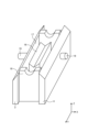
- FIG. 1 is a schematic perspective view of a first coating device of the present invention.
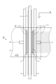
- FIG. 2 is a sectional view taken along an XZ plane outside the side plate of the coating device shown in FIG. 1;
- FIG. 2 is a top view of the coating apparatus of FIG. 1;
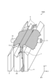
- FIG. 2 is a schematic perspective view of the coating device of FIG. 1 with a coating bar removed.
- It is a schematic perspective view of the second coating device of this invention. It is a diagram illustrating a state in which a coating liquid is supplied to a second coating device of the present invention, and the coating bar is omitted from the illustration.
- It is a sectional view of the XZ plane outside the side plate of the conventional coating device.
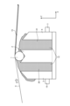
- FIG. 2 is a cross-sectional view of the coating device taken along the XZ plane, illustrating the coating process when the coating liquid supplied to the upstream container is insufficient.
- FIG. 3 is a cross-sectional view of the coating device taken along the XZ plane, illustrating the coating process when the coating liquid supplied to the downstream container is insufficient.
- FIG. 3 is a schematic perspective view of the coating device of Patent Document 4 with the coating bar removed.
- FIG. 1 is a schematic perspective view of the first coating device
- FIG. 2 is a cross-sectional view of the first coating device on the XZ plane
- FIG. 3 is a top view of the first coating device in the XY plane looking down from vertically above.
- the first coating device 100 includes a coating bar 1 extending in the web width direction with respect to the web 9, and a partition member disposed vertically below the axial center of the coating bar 1 and extending in the web width direction. 2.
- An upstream main plate 3 and a downstream main plate 4 arranged parallel to each other on the upstream and downstream sides of the web conveyance direction with the partition member 2 in between, the inner side in the web width direction of both ends of the partition member 2 in the web width direction It is provided so as to be in contact with the side plate 5, the partition member 2, the upstream main plate 3, the downstream main plate 4, and the side plate 5, which are arranged on the upstream side.
- a bottom plate (not shown) forming the container 20 and the downstream container 21 is provided.
- the coating liquid 12 is supplied to the upstream container 20 and the downstream container 21 from the upstream container coating liquid supply port 10 and the downstream container coating liquid supply port 11, respectively.
- the width L2 between the two side plates 5 is the width over which the coating liquid is applied to the web 9, that is, the width set as the desired coating width.
- the side plate 5 may be slidable in the web width direction, and in that case, the sliding range of the side plate 5 becomes the adjustment margin for the coating width.
- FIG. 4 is a schematic perspective view of the first coating device with the coating bar removed.
- the partition member 2 is a plate-shaped member, and a V-shaped support portion 2a is formed on the side that supports the coating bar 1, and the coating bar 1 is supported by the support portion 2a.
- the support portion 2a is V-shaped, but may be arc-shaped as long as it can support the coating bar 1.
- the support portion 2a of the partition member 2 is formed with an inclined surface 6 for discharging the coating liquid from a position within the range of the web width L1 of the web 9 to be coated and outside the side plate 5 in the web width direction. ing.
- the inclined surface 6 is formed by cutting out the downstream surface of the support section 2a, and functions as a flow path through which the coating liquid flows out from between the coating bar 1 and the support section 2a.
- the inclined surface 6 is formed to be inclined vertically downward from a position vertically below the coating bar 1 toward the downstream side in the web conveyance direction.
- the inclined surface 6 may be a flat surface that slopes vertically downward toward the upstream side in the web conveyance direction, as long as it can discharge the coating liquid from between the coating bar 1 and the partition member 2.
- both ends of the partition member 2 are all sloped surfaces, but the sloped surface 6 is provided only around the side plate 5, and the support portion 2a remains as it is without forming the sloped surface 6 on the end side. You can also use it as
- the coating bar 1 for example, a wire bar with grooves formed by winding wire on the outer circumferential surface of the bar, a rolled bar with grooves formed on the outer circumferential surface of the bar by rolling processing, a small-diameter gravure roll, etc. can be used. can.
- the material of the coating bar 1 is preferably stainless steel, particularly SUS304 or SUS316.
- the surface of the coating bar 1 may be subjected to surface treatment such as hard chrome plating. If the diameter of the coating bar 1 is too large, streak-like coating defects along the conveyance direction called rib streaks are likely to occur, and if it is too small, the deflection of the coating bar 1 will become large. is preferably 4 to 20 mm.
- the coating bar may be rotated in a so-called driven rotation state in which the coating bar 1 is pressed against the web 9 and rotated by the frictional force with the web 9, or may be rotated by a drive device such as a motor.
- a drive device When rotated by a drive device, it is preferable that the coating bar 1 be rotated in the transport direction of the web 9 at substantially the same speed as the transport speed of the web 9 in order to prevent the web 9 from being damaged.
- substantially the same speed means that the speed difference between the circumferential speed of the coating bar 1 and the conveyance speed of the web 9 is within a range of ⁇ 10%.
- the coating bar 1 may be rotated at a speed different from the transport speed of the web 9 or in a direction opposite to the transport direction.
- the side plate 5 has a gap of 0.3 mm between each component in order to prevent the coating liquid from leaking outside the coating width, to improve the sealing of the container as much as possible, and to not impair sliding properties. It is preferable to do the following.
- the material is not particularly limited, but a resin material with high sliding properties is preferred.
- the means for sliding the side plate 5 in the width direction may be a motor, an air cylinder, or manually. By making the side plate 5 slidable without disassembling the device, the coating width can be easily adjusted when changing production types.
- the partition member 2 is installed to partition the flow path of the coating liquid supplied to the upstream side and the downstream side with respect to the web conveyance direction of the coating bar 1.
- its shape is not particularly limited, and it does not need to be in contact with the coating bar 1 as long as it is sufficiently close to it. It is preferable that the gap between the parts closest to the coating bar is 1 mm or less.
- FIG. 5 is a schematic perspective view of a second coating apparatus 100A of the present invention.
- the support portion 2a of the partition member 2A is provided with a flow path for discharging the coating liquid, the bottom of which extends vertically downward from a position vertically below the coating bar 1 toward the downstream side in the web conveyance direction.
- Four grooves 7 are provided which are inclined to the side. It is sufficient that at least one groove 7 is provided within the range of the web width of the partition member 2A and outside of the side plate 5 in the web width direction, and within the range of the web width of the partition member 2A and outside of the side plate 5 in the web width direction. It is preferable to provide them at both outer ends in the width direction.
- the reason why four grooves 7 are provided in the second coating device 100A is to accommodate changes in web width, and four or more grooves 7 may be provided.
- the bottom surface of the groove 7 may be inclined vertically downward toward the upstream side in the web conveyance direction.
- the size of the groove 7 is preferably determined depending on the flow rate of the coating liquid to be discharged.
- the shape of the cross section of the groove 7 in the web width direction is not particularly limited as long as it satisfies the discharge function, such as a rectangular or elliptical shape. If there is a part where the coating bar 1 is not supported in the range where the coating width is adjusted, if the coating width adjustment range is significantly widened, the deflection of the coating bar 1 at that part will increase, which will affect the coating quality.
- the partition member 2A directly contacts and supports the coating bar 1 from below over the entire coating width, the coating bar 1 is supported in the portion where the groove 7 is formed.
- the coating bar 1 is not supported locally and does not have a large effect on the deflection of the coating bar 1. Therefore, even within the range in which the coating width can be adjusted, stable coating can be achieved without degrading the coating quality, and the range in which the coating width can be adjusted is dramatically expanded.
- FIG. 6 is a diagram illustrating how the coating liquid 12 is being supplied to the second coating device 100A, and the coating bar 1 is omitted from the illustration.
- the coating liquid 12 supplied from the upstream container coating liquid supply port 10 and the downstream container coating liquid supply port 11 accumulates in the upstream container 20 and the downstream container 21, and is transmitted from the upper surface of the partition member 2A to the support portion 2a.
- the web spreads toward both ends in the web width direction. Since the support part 2a of the partition member 2A has a groove 7 on the outer side in the web width direction than the side plate 5, the coating liquid is discharged from the groove 7 to the outside of each container, and the coating liquid is on the upper surface of the partition member 2A. It never accumulates.
- FIG. 7 is a cross-sectional view of the conventional coating apparatus 100' taken along the XZ plane at the end in the width direction.
- FIG. 8 is a diagram illustrating a state in which a coating liquid is supplied to a conventional coating apparatus 100', and the coating bar 1 is omitted from the illustration.
- the support portion 2a of the partition member 2' that supports the coating bar 1 extends across the entire width of the web with the same cross section.
- the coating liquid In order to support the coating bar 1, it is necessary to contact the partition member 2' from below, but since the coating bar 1 has a cylindrical shape, a commonly used partition having a V-shaped support part 2a is used.
- the coating liquid accumulates in the gap 13 between the coating bar 1 and the support portion 2a provided on the partition member 2'.
- the coating liquid spreads in the width direction along this gap 13 and is not discharged, so that the coating liquid spreads to the outside of the side plate 5 and the coating bar 1 becomes wet, as shown in FIG. That is, the coating liquid is applied to the web even outside the side plate 5, and no uncoated portions can be formed.
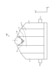
- FIG. 9 is a schematic perspective view of a third coating apparatus 100B of the present invention.
- the third coating device 100B serves as a flow path for discharging the coating liquid, and extends from a position vertically below the coating bar 1 through the interior of the partition member 2B to a downstream side of the partition member 2B in the web conveyance direction. It has four holes 8 extending to the sides. It is sufficient that at least one hole 8 is provided within the range of the web width of the partition member 2B and outside of the side plate 5 in the web width direction; It is preferable to provide them at both outer ends in the width direction.
- the reason why the four holes 8 are provided in the third coating device 100B is to accommodate changes in the web width, and four or more holes 8 may be provided.
- the hole 8 may penetrate through the inside of the partition member 2B and reach the upstream side surface of the partition member 2 in the web conveyance direction.
- the cross-sectional shape of the hole 8 is not limited to a circular, oval, or rectangular shape, and its size is determined depending on the flow rate of the coating liquid used.
- the partition member 2B directly contacts and supports the coating bar 1 from below, and can support the coating bar 1 even within the range where the hole 8 is formed. 1, and stable coating can be performed without degrading the coating quality even within the range where the coating width is adjusted.
- FIG. 10 is a schematic perspective view of a fourth coating apparatus 100C of the present invention.
- FIG. 11 is a cross-sectional view on the XZ plane of a portion of the fourth coating device 100C where the support body 14 is present.
- FIG. 12 is a schematic perspective view of the partition member 2C in a portion where the support body 14 is present.
- the fourth coating apparatus 100C includes partition members extending in the web width direction, while supports 14 that support the coating bar 1 from below are arranged at intervals in the web width direction.
- 2C is a coating device arranged vertically below the axial center of the coating bar 1. As shown in FIG.
- the partition member 2 extending in the web width direction separates the coating bar 1 from the upstream side and the downstream side vertically below the axial center of the coating bar 1. It is partitioned on the side.
- the flow path for discharging the coating liquid is formed by passing through the inside of the partition member 2 from a position vertically below the coating bar 1 at a location where the support 14 is not present in the web width direction.
- a form having an inclined surface 6C vertically downward is shown.
- FIG. 12 shows an embodiment in which the support body 14 is a roller. The outer periphery of the roller of the support body 14 is in contact with the coating bar 1, and since it rotates together with the coating bar 1 about the shaft 22 attached to the partition member 2C as the rotation axis, the coating bar 1 and the support body 14 are not worn.
- support by rollers is shown in FIGS. 10, 11, and 12 as the support 14, it may be a V-shaped support, an arc-shaped support, or a support that supports the coating bar 1 while rotating.
- the form is not limited as long as it can support the coating bar 1, such as a ball.
- the material of the support body 14 in order to reduce wear of the coating bar 1, it is preferable to use a material whose hardness is lower than that of the coating bar 1 for the surface layer of the support body.
- the spacing between the supports 14 arranged along the longitudinal direction of the coating bar 1 is preferably narrow, since if the spacing is too wide, the deflection of the coating bar 1 will increase.
- As a guideline it is preferable to arrange the coating bar 1 so that its deflection is 10 ⁇ m or less.
- the amount of deflection is calculated by applying the reaction force in the out-of-plane direction of the web 9 calculated from the tension applied to the running direction of the web 9 as a uniformly distributed load applied to the coating bar 1, using the support 14 as a support point, and applying the reaction force in the out-of-plane direction of the web 9 to the coating bar It can be determined from a material mechanics formula using a moment of inertia of 1 and Young's modulus.
- the coating bar 1 is contacted and supported from below by the support 14, so that the deflection of the coating bar 1 can be suppressed and the coating quality can be improved. Can be applied stably without dropping.
- the support 14 may be provided within the range of the inclined surface 6 of the partition member 2 as well.
- Examples of the material for the support 14 include metals such as iron, stainless steel, aluminum, and copper, nylon, acrylic resin, vinyl chloride resin, synthetic resins such as tetrafluoroethylene, and rubber. Moreover, the shape may be plate-like or block-like.
- Coating method A method of coating a web using the first to fourth coating devices 100, 100A, 100B and 100C will be described.
- Coating liquid 12 is supplied from upstream container coating liquid supply port 10 and downstream container coating liquid supply port 11 to upstream container 20 and downstream container 21, respectively. Coating is performed on the conveyed web 9 by raising the coating device and pressing the coating bar 1 against the lower surface of the web 9 from below.
- the angle at which the web 9 wraps the coating bar 1 is not particularly limited, it is more preferably 0 degrees or more and 20 degrees or less.
- the coating liquid supply means gear pumps, diaphragm pumps, and Mono pumps having quantitative properties and low pulsation properties are preferable.
- the coating liquid 12 discharged from the pump may be supplied to the container via a filter or defoaming means.
- the coating liquid supplied from the coating liquid tank to the container via the pump and the supply port is circulated to the coating liquid tank via the flow paths of the coating apparatuses 100, 100A, 100B, and 100C.
- FIG. 13 is a diagram illustrating a situation when the coating liquid 12 supplied to the upstream container 20 is insufficient
- FIG. 14 is a diagram illustrating a situation when the coating liquid 12 supplied to the downstream container 21 is insufficient.
- FIG. 3 is a diagram illustrating the situation, and both are cross-sectional views of the coating device on the XZ plane.
- the partition member 2 and are generated as air bubbles 15 on the upstream side of the coating bar 1, and then pass between the web 9 and the coating bar 1, and the air bubbles 15 are mixed into the coating film. Put it away. If the air bubbles 15 are mixed into the coating film as described above, defects such as coating omissions due to the air bubbles will occur. Alternatively, if the air bubbles 15 continue to remain between the web 9 and the coating bar 1, a streak-like defect occurs. On the other hand, if the supplied flow rate is too large, problems such as an increase in foreign matter and air bubbles passing through the filter occur.
- the balance between the flow rate of the coating liquid 12 supplied to the upstream container 20 and the flow rate of the coating liquid 12 supplied to the downstream container 21 is adjusted to minimize air bubbles. It is preferable to set the flow rate so that this does not occur.
- the coating liquid 12 supplied to the upstream container 20 and the downstream container 21 is preferably adjusted according to coating conditions such as the thickness of the coating film, the conveyance speed of the web 9, and the rotation speed of the coating bar 1. Further, the web targeted by this coating method is not particularly limited as long as it is in the form of a long sheet such as paper, film, or metal foil.
- the viscosity of the coating liquid 12 used in the coating apparatus according to this embodiment is preferably 0.1 Pa ⁇ s or less. When the viscosity of the coating liquid 12 is high, a living phenomenon may occur and coating streaks may occur.
- the coating amount of the coating liquid 12 is preferably 100 g/m 2 or less in a wet state immediately after coating. Generally, in the bar coating method, the coating quality is better when the coating weight is low, so the coating weight is preferably in the range of 4 to 50 g/m 2 .
- the amount of coating can be adjusted by adjusting the size of the groove formed in the coating bar 1.
- the size of the groove can be determined by changing the wire diameter of the wire to be wound if the coating bar 1 is a wire bar, or by rolling with a die with a different groove depth and/or groove pitch if the coating bar 1 is a rolling bar. It can be changed by processing.
- PET polyethylene terephthalate
- an intrinsic viscosity also called intrinsic viscosity
- 0.62 dl/g measured in o-chlorophenol at 25°C according to the standard of JIS K7367-5 (2000 edition)
- this unstretched film was heated with a group of rolls heated to 80°C, further stretched by a factor of 3.2 in the longitudinal direction while being heated with an infrared heater, and then stretched with cooling rolls adjusted to 50°C. It was cooled to form a uniaxially stretched resin film.
- the width of the resin film was 1700 mm.
- the coating liquid 12 was applied to the lower surface of this resin film traveling at a speed of 200 m/min.
- the resin film coated with the coating liquid 12 is guided into an oven at 90°C and heated, and then the coating liquid 12 is dried in an oven at 100°C, and the resin film is stretched in the width direction.
- the resin film was stretched by 3.7 times and then heat-set while being subjected to a relaxation treatment of 5% in the width direction in an oven at 220°C. In this way, a biaxially stretched film having a film formed with the coating liquid 12 on one side was obtained.
- the tension between the longitudinal stretching machine and the transverse stretching machine was controlled by a dancer roll so that the tension per unit width in the running direction of the resin film was 8000 N/m.
- Coating liquid 12 is an emulsion of a polyester copolymer (components: 90 mol% terephthalic acid, 10 mol% 5-sodium sulfoisophthalic acid, solvent: 96 mol% ethylene glycol, 3 mol% neopentyl glycol, 1 mol% diethylene glycol).
- a polyester copolymer components: 90 mol% terephthalic acid, 10 mol% 5-sodium sulfoisophthalic acid, solvent: 96 mol% ethylene glycol, 3 mol% neopentyl glycol, 1 mol% diethylene glycol.
- a melamine crosslinking agent manufactured by Nippon Carbide Kogyo Co., Ltd.: MW-390
- colloidal silica particles having an average particle size of 0.1 ⁇ m were added to prepare a mixed solution.
- This coating liquid 12 was 2 mPa ⁇ s at a temperature of 25°C.
- This coating liquid is applied to the upstream container coating liquid supply port 10 and the downstream container coating liquid supply port 11 of the first coating device 100 in FIG. It was supplied to the upstream container 20 and the downstream container 21.
- As the coating bar 1 a stainless steel round bar with a diameter of 12.7 mm and a length of 2000 mm was wound with a wire having a linear diameter of 0.1 mm (manufactured by Kano Shoji Co., Ltd.).
- the side plates 5 were arranged so that the side plate interval L2 was 1600 mm (L3: 1000 mm).
- the first coating device 100 coating was carried out while pressing the coating bar 1 against the conveyed web 9 and rotating the coating bar 1 in a driven manner.
- the coating bar 1 was supported by a V-shaped support portion 2a of the partition member 2.
- the partition member 2 has a V-shaped sloped surface 6 with the downstream side cut off in the coating adjustment width (300 mm on each side).
- the coating results are shown in Table 1. With respect to the side plate spacing L2 (1600 mm), the width of the coating on the web was L2+8 mm, and it was confirmed that the film could be formed without any problems.
- the coating bar 1 was removed once, and the coating liquid was continued to flow at a rate of 50 L/min for 3 minutes, and then the coating bar 1 was removed again. I attached it and applied the coating, but I was able to form the uncoated areas without any problems.
- the supply rate of the coating liquid without bubbles from both the upstream side and the downstream side was 10 L/min on the upstream side and 27 L/min on the downstream side.
- Example 2 Using the second coating device 100A, the coating bar 1 was supported over its entire width by the V-shaped support portion 2a of the partition member 2A, as shown in FIG. Regarding the coating adjustment width of the partition member 2A, a V-shaped support portion 2a having grooves 7 intermittently dug in the web width direction was used. The grooves 7 had a width of 10 mm and a depth of 20 mm, and the center distance between the grooves in the web width direction was 140 mm. Coating was carried out in the same manner as in Example 1 except for this. The coating results are shown in Table 1.
- the width coated on the web was L2+10 mm, and it was confirmed that the film could be formed without any problems. Further, in the same manner as in Example 1, even if the coating liquid was continued to flow for 3 minutes at a supply rate of 50 L/min and then coated again, a non-coated portion could be formed.
- the supply rate of the coating liquid without any bubbles from both the upstream side and the downstream side was 10 L/min on the upstream side and 25 L/min on the downstream side.
- Example 3 Using the third coating device 100B, the coating bar 1 was supported over its entire width by the V-shaped support portion 2a of the partition member 2B, as shown in FIG. Regarding the coating adjustment width of the partition member 2B, a V-shaped support portion 2a having holes 8 disposed intermittently in the web width direction was used. The hole 8 had a diameter of 8 mm and communicated with the outside of the partition member 2B at a position 10 mm downward in the Z direction. The center distance between the holes in the web width direction was 142 mm. Coating was carried out in the same manner as in Example 1 except for this. The coating results are shown in Table 1.
- the width coated on the web was L2+11 mm, and it was confirmed that the film could be formed without any problems. Further, in the same manner as in Example 1, even if the coating liquid was continued to flow for 3 minutes at a supply rate of 50 L/min and then coated again, a non-coated portion could be formed.
- the supply rate of the coating liquid without any bubbles from both the upstream side and the downstream side was 10 L/min on the upstream side and 25 L/min on the downstream side.
- the coating bar 1 was supported by rollers (supports 14) arranged intermittently in the web width direction, as shown in FIG.
- the holes 8 are arranged intermittently in the width direction of the web in the part where the support 14 is not present, and the coating bar 1 is in the shape where the holes 8 are arranged intermittently in the web width direction in the part where the support 14 is present.
- a shape having an inclined surface 6C that is inclined vertically downward by 5 degrees toward the downstream side in the web conveyance direction from a vertically downward position was applied.
- the hole 8 had a diameter of 8 mm and communicated with the outside of the partition member 2B at a position 10 mm downward in the Z direction.
- the center distance between the holes in the web width direction was 192 mm.
- Coating was carried out in the same manner as in Example 1 except for this.
- the coating results are shown in Table 1.
- the width coated on the web was L2+8 mm, and it was confirmed that the film could be formed without any problems.
- the supply rate of the coating liquid without bubbles from both the upstream side and the downstream side was 10 L/min on the upstream side and 28 L/min on the downstream side.
- Example 1 A coating device similar to Example 1 except that a partition plate having a V-shaped support portion 2a formed over the entire width is used, and the outside of the side plate is a V-shaped block (no flow path) with the same cross section. Coating was carried out under the same conditions. The coating results are shown in Table 1. With respect to the width L2 (1600 mm) between the side plates regulated by the side plates, the width coated on the web exceeded L2+30 mm, and the entire width of the web was coated. Thereafter, in the transverse stretching step, both ends of the web in the width direction were held with clips, but because the coating liquid was present between the clips and the web, the clips slipped and came off, making it impossible to stretch.
- Example 2 Further, in the same manner as in Example 1, after the coating liquid was continued to flow for 3 minutes at a supply rate of 50 L/min, coating was performed again, but no uncoated portion could be formed.
- the supply rate of the coating liquid without any bubbles from both the upstream side and the downstream side was 11 L/min on the upstream side and 25 L/min on the downstream side.
- FIG. 15 shows the coating apparatus described in Patent Document 4, with the coating bar removed.
- a container 17 is constructed by arranging a side plate 18 at the end of the coating device in the web width direction.
- the partition member 16 has a V-shaped support portion.
- the partition member 16 has a length of 1250 mm in the web width direction, and when the coating width is adjusted to be wider than 1250 mm by sliding the side plate 18 outward in the web width direction, the side plate 18 at the end in the web width direction becomes a partition.
- the upstream and downstream containers are spaced apart from the member 16 and communicate with each other.
- Example 1 coating was carried out in the same manner as in Example 1, except that the coating width was adjusted to be wide so that the partition member 16 and the side plate 18 were separated from each other.
- the coating results are shown in Table 1. With respect to the width L2 (1600 mm) between the side plates regulated by the side plates 18, the width coated on the web was L2+11 mm, and it was confirmed that the film could be formed without any problems. Further, as in Example 1, even if the coating liquid was continued to flow for 3 minutes at a supply rate of 50 L/min and then coated again, a non-coated portion could be formed. The supply rate of the coating liquid without bubbles from both the upstream side and the downstream side was 20 L/min on the upstream side and 32 L/min on the downstream side.
- Controllability of coating fluid supply amount In order to prevent bubbles from being trapped during coating, it is better to have a large total of the upstream and downstream coating liquid supply amounts, but this poses the problem of increasing the capacity of the coating liquid supply pump. This may cause problems such as an increase in the amount of foreign matter passing through the filter. It is better to keep the total amount of coating liquid supplied as low as possible while preventing bubbles from being trapped during coating. Therefore, judging from the applicant's past coating experience, the controllability of the coating liquid supply amount was evaluated based on the following criteria. ⁇ (Good): The total supply amount of the coating liquid is 50 L/min or less. ⁇ (Poor): The total supply amount of the coating liquid exceeds 50 L/min.
- the coating device of the present invention can be used to coat a coating liquid onto a web-like object such as a film, paper, or metal foil.
Abstract
Provided is a coating device that can form a non-coated portion on an end part of a web and that can adjust the coating width without decreasing productivity. A coating device according to the present invention comprises: a coating bar extending in the web width direction; a partitioning member arranged vertically below the axial center of the coating bar and extending in the web width direction; and an upstream container and a downstream container having side plates of which both ends in the web width direction are arranged further inward in the web width direction than both ends of the partitioning member in the web width direction, the upstream container and the downstream container being arranged at the upstream side and the downstream side, respectively, in the web conveyance direction, with the partitioning member interposed therebetween. A flow passage whereby a coating liquid is discharged from a position within the range of the web width and further outward in the web width direction than the side plates is formed in the partitioning member.
Description
本発明は、塗工装置および塗膜付きウェブの製造方法に関する。
The present invention relates to a coating device and a method for producing a coated web.
従来、搬送される熱可塑性樹脂フィルム等のウェブの表面に塗液を均一に塗工する方法として、バーコート法がある。これは、ウェブの幅方向に延在する塗工バーを、走行するウェブの下面に押し付け、ウェブとの間に生じる摩擦力、もしくはモーター等によって付与される駆動力によって回転することで予めウェブに供給した過剰量の塗液を掻き落とす(計量する)方法である。
Conventionally, there is a bar coating method as a method for uniformly applying a coating liquid to the surface of a web such as a thermoplastic resin film being transported. This is done by pressing a coating bar extending in the width direction of the web against the lower surface of the running web and rotating it by the frictional force generated between it and the web or by the driving force provided by a motor etc. This is a method of scraping off (measuring) the excess amount of coating liquid that has been supplied.
しかしながら、バーコート法による塗液の塗布は、塗液を掻き落とす際に塗膜中に気泡を噛み込み、スジや欠点となる問題が発生することがある。これは走行するウェブによって随伴される空気の影響で、塗工部の上流側で濡れ始める際に塗液中に空気を巻き込むことや、回転する塗工バーによって随伴される空気の影響で、塗工バー近傍の気液界面において塗液中に空気を巻き込むことなどが原因であった。これに対して特許文献1で開示されているように、塗工バーの上流側と下流側のそれぞれに液を供給することで空気の巻き込みを防止する装置構成が一般的に知られている。例えば上流側から下流側へ走行するウェブの速度が大きい場合には、上流側からの液供給を増やすことで走行するウェブによって随伴される空気の巻き込みを防止し、走行するウェブに対して順回転する塗工バーの回転速度が大きい場合には、下流側からの液供給を増やすことで、回転する塗工バーの回転によって随伴される空気の巻き込みを防止する。このように塗工条件に合わせて塗工バーの上流側と下流側に供給される塗液の量を調節することで空気の巻き込みを防止している。また塗工バーは一般的に直径数十mm、長さ数百mm~数千mmの円柱形状であるため、自重やウェブから受ける力によって撓みが生じやすい。この撓みを防止する方法として、特許文献1が開示しているように、塗工バーの幅方向に延在するV字形状や円弧形状の断面を有する支持体を塗工バーに対して下から接触させて支持する構成が採用されることが多く、この構成は塗工バーの上流側と下流側を支持体で仕切る構成となっている。上流側と下流側を仕切ることによって、上記上流側から供給された塗液は塗工バーの上流側に、下流側から供給された塗液は塗工バーの下流側へ供給されるようになっており、それぞれに供給する塗液の量を個別に調節できるので、前述の空気の巻き込みに対して塗液の量を容易に調節できる。
However, when applying a coating liquid using the bar coating method, air bubbles may be trapped in the coating film when the coating liquid is scraped off, causing problems such as streaks and defects. This is due to the influence of air entrained by the running web, which causes air to be drawn into the coating liquid when it starts to get wet on the upstream side of the coating area, and due to the influence of air entrained by the rotating coating bar. The cause was air being drawn into the coating liquid at the air-liquid interface near the coating bar. On the other hand, as disclosed in Patent Document 1, a device configuration is generally known that prevents air entrainment by supplying liquid to each of the upstream and downstream sides of the coating bar. For example, when the speed of the web running from the upstream side to the downstream side is high, increasing the liquid supply from the upstream side prevents the entrainment of air entrained by the running web, and rotates in the same direction as the running web. When the rotational speed of the coating bar is high, increasing the liquid supply from the downstream side prevents air entrainment caused by the rotation of the rotating coating bar. In this way, air entrainment is prevented by adjusting the amount of coating liquid supplied to the upstream and downstream sides of the coating bar in accordance with the coating conditions. Furthermore, since the coating bar is generally cylindrical with a diameter of several tens of mm and a length of several hundred to several thousand mm, it is likely to be bent due to its own weight or the force received from the web. As a method for preventing this deflection, as disclosed in Patent Document 1, a support body having a V-shaped or arc-shaped cross section extending in the width direction of the coating bar is placed from below against the coating bar. A configuration in which the coating bar is supported in contact is often adopted, and in this configuration, the upstream side and downstream side of the coating bar are partitioned by a support body. By separating the upstream and downstream sides, the coating liquid supplied from the upstream side is supplied to the upstream side of the coating bar, and the coating liquid supplied from the downstream side is supplied to the downstream side of the coating bar. Since the amount of coating liquid supplied to each can be adjusted individually, the amount of coating liquid can be easily adjusted to prevent the above-mentioned air entrainment.
バーコート法の適用先として、ウェブの製膜ラインの途中に導入して製膜中のウェブに対して塗工と乾燥を行うインラインコーティング法と、ロール状に巻かれたウェブを巻き出す機構と巻き取る機構とを備えたラインの途中に導入して、搬送されるウェブに対して塗工と乾燥を行うオフラインコーティング法がある。このうちインラインコーティング法では、ウェブの中でも特にPETフィルムやPPフィルムなどの延伸フィルムにおいて、加熱しつつクリップやピンでウェブ端部を把持してウェブ幅方向に延伸を行うテンターオーブンに搬送される前に、コーティングを行うことが知られている。インラインコーティング法においてはウェブの端部をクリップやピン等で把持するため、把持に影響が出ないよう端部には塗液を塗工しないことが重要である。また製品によってウェブの幅はさまざまであるため、塗液を塗工する幅(以下、塗工幅と表記する)と塗液を塗工しない幅(以下、非塗工幅と表記する)を適切に調整できる機構が塗工装置には求められる。
The bar coating method is applied to the in-line coating method, which is introduced in the middle of the web film production line to coat and dry the web during film formation, and the mechanism that unwinds the web wound into a roll. There is an offline coating method that is introduced in the middle of a line equipped with a winding mechanism and coats and dries the web being transported. Among these methods, the in-line coating method is used to apply heat to stretched films such as PET films and PP films before being conveyed to a tenter oven, where the ends of the web are held with clips or pins while being heated and stretched in the width direction of the web. It is known that coating is applied to In the in-line coating method, the ends of the web are gripped with clips, pins, etc., so it is important not to apply the coating liquid to the ends so as not to affect gripping. In addition, since the width of the web varies depending on the product, the width to which the coating liquid is applied (hereinafter referred to as the coating width) and the width to which the coating liquid is not applied (hereinafter referred to as the non-coating width) are determined appropriately. Coating equipment is required to have a mechanism that allows for adjustment.
前述のオフラインコーティング法においても製品幅に合わせて塗工幅を調整することで、必要以上に塗液を消費しないように端部を非塗工にする場合があり、塗工装置に塗工幅を調整できる機能が備わっていることは生産性を向上させる上で重要である。
そこで、例えば特許文献2では、ウェブの両端を部材などによって持ち上げ、塗工装置と非接触にすることで端部に非塗工幅を形成する方法を開示している。また、特許文献3では、塗工幅に合わせて装置の幅を可変することができる構造の塗工装置を開示している。さらに特許文献4では、容器内の液だまり幅を調整する方法を開示している。この特許文献4が開示している方法は作業性がよく、塗工中に自由に塗工幅を調整することができるため、生産性を悪化させることなく塗工幅を変更できる。 Even in the offline coating method mentioned above, by adjusting the coating width according to the product width, the edges may be left uncoated to avoid consuming more coating liquid than necessary. Having the ability to adjust is important in improving productivity.
Therefore, for example,Patent Document 2 discloses a method of forming a non-coating width at the ends by lifting both ends of the web with a member or the like and making the web non-contact with the coating device. Further, Patent Document 3 discloses a coating device having a structure in which the width of the device can be varied according to the coating width. Further, Patent Document 4 discloses a method for adjusting the width of a liquid pool in a container. The method disclosed in Patent Document 4 has good workability, and the coating width can be freely adjusted during coating, so the coating width can be changed without deteriorating productivity.
そこで、例えば特許文献2では、ウェブの両端を部材などによって持ち上げ、塗工装置と非接触にすることで端部に非塗工幅を形成する方法を開示している。また、特許文献3では、塗工幅に合わせて装置の幅を可変することができる構造の塗工装置を開示している。さらに特許文献4では、容器内の液だまり幅を調整する方法を開示している。この特許文献4が開示している方法は作業性がよく、塗工中に自由に塗工幅を調整することができるため、生産性を悪化させることなく塗工幅を変更できる。 Even in the offline coating method mentioned above, by adjusting the coating width according to the product width, the edges may be left uncoated to avoid consuming more coating liquid than necessary. Having the ability to adjust is important in improving productivity.
Therefore, for example,
しかしながら、特許文献2が開示している方法では、ウェブに折れジワなどが発生して搬送に悪影響をおよぼすことがある。また、特許文献3が開示している塗工装置では、製品の品種を切り替える際には塗工装置を分解した後に再組立をしなければならず、生産性を悪化させてしまう。さらに、特許文献4が開示している方法では、塗工幅を変更する部材の摺動域においては、上流側容器と下流側容器が連通しているため、上流側と下流側を仕切ることができていない。その結果、塗工する幅によっては塗工バーの上流側と下流側に供給される塗液の流量を個別に調整することができない。
However, in the method disclosed in Patent Document 2, folds and wrinkles may occur in the web, which may adversely affect conveyance. Further, in the coating device disclosed in Patent Document 3, when changing the product type, the coating device must be disassembled and then reassembled, which deteriorates productivity. Furthermore, in the method disclosed in Patent Document 4, in the sliding area of the member that changes the coating width, the upstream side container and the downstream side container communicate with each other, so it is not possible to partition the upstream side and the downstream side. I haven't been able to do it. As a result, depending on the width to be coated, it is not possible to individually adjust the flow rates of the coating liquid supplied to the upstream and downstream sides of the coating bar.
本発明は、塗工バーの上流と下流の塗液の流量を個別に制御でき、ウェブの端部に非塗工の部分を形成でき、かつ生産性を低下させることなく塗工幅を調整できる塗工装置および塗工方法を提供する。
The present invention makes it possible to individually control the flow rate of the coating liquid upstream and downstream of the coating bar, to form a non-coated part at the end of the web, and to adjust the coating width without reducing productivity. Provides coating equipment and coating methods.
上記課題を解決する本発明は、走行するウェブに塗液を塗工する塗工装置であって、ウェブ幅方向に延在する塗工バーと、上記塗工バーの鉛直下方に配置され、ウェブ幅方向に延在する仕切り部材と、前記仕切り部材のウェブ幅方向の両端よりもウェブ幅方向の内側に配置された側板を備え、上記仕切り部材を挟んでウェブ搬送方向の上流側および下流側にそれぞれ配置され、塗液を貯留する上流側容器および下流側容器と、を有し、上記仕切り部材は、前記上流側容器と前記下流側容器とを仕切る部材であって、ウェブ幅の範囲内、かつ上記側板よりもウェブ幅方向の外側の位置から塗液を排出する流路が形成されている。
The present invention, which solves the above problems, is a coating device that coats a running web with a coating liquid, and includes a coating bar extending in the width direction of the web, and a coating device disposed vertically below the coating bar, A partition member extending in the width direction, and a side plate disposed inside in the web width direction from both ends of the partition member in the web width direction, and located on the upstream and downstream sides in the web conveyance direction with the partition member in between. It has an upstream container and a downstream container that are arranged to store the coating liquid, and the partition member is a member that partitions the upstream container and the downstream container, and the partition member is a member that partitions the upstream container and the downstream container, and the partition member is a member that partitions the upstream container and the downstream container, and Further, a flow path is formed for discharging the coating liquid from a position outside the side plate in the web width direction.
本発明の塗工装置は、以下の(1)~(6)のいずれか、または複数の態様であることが好ましい。
(1)上記塗液を排出する流路が、上記塗工バーの鉛直下方の位置からウェブ搬送方向の上流側または下流側に向かうにつれて鉛直下方に傾斜している平面である。
(2)上記塗液を排出する流路が、底面が上記塗工バーの鉛直下方の位置からウェブ搬送方向の上流側または下流側に向かうにつれて鉛直下方に傾斜している1つ以上の溝である。
(3)上記塗液を排出する流路が、上記塗工バーの鉛直下方の位置から、上記仕切り部材の内部を貫通して、上記仕切り部材のウェブ搬送方向の上流側または下流側の側面に至る1つ以上の穴である。
(4)上記側板がウェブ幅方向に摺動可能である。
(5)上記仕切り部材が上記塗工バーを下方から支持する。
(6)上記塗工バーを下方から支持する支持体がウェブ幅方向に間をあけて配置されている。
ただし、本発明の塗工装置の構成には、塗工対象のウェブは含まない。 The coating apparatus of the present invention preferably has any one or more of the following embodiments (1) to (6).
(1) The flow path for discharging the coating liquid is a plane that is inclined vertically downward from a position vertically below the coating bar toward the upstream side or the downstream side in the web conveyance direction.
(2) The flow path for discharging the coating liquid is one or more grooves whose bottom surfaces are inclined vertically downward from a position vertically below the coating bar toward the upstream or downstream side in the web conveyance direction. be.
(3) A channel for discharging the coating liquid extends from a position vertically below the coating bar, penetrates the inside of the partition member, and extends to the upstream or downstream side of the partition member in the web conveyance direction. One or more holes leading to the hole.
(4) The side plate is slidable in the width direction of the web.
(5) The partition member supports the coating bar from below.
(6) Supports that support the coating bar from below are arranged at intervals in the web width direction.
However, the configuration of the coating apparatus of the present invention does not include the web to be coated.
本発明の塗膜付きウェブの製造方法は、本発明の塗工装置を用い、上記上流側容器および上記下流側容器に塗液を供給しつつ、所定の速度で上流側から下流側へ搬送されるウェブに上記塗工バーを押し当て、上記塗液を上記ウェブに塗工する。
次に本発明における用語の意味を説明する。
「ウェブ搬送方向」とは、塗工装置で塗工されるウェブが搬送される方向のことを言う。
「ウェブ幅方向」とは、塗工装置で塗工されるウェブの幅の方向のことを言う。
「上流側」とは、塗工装置をウェブの搬送ラインに設置したときに、ウェブが搬送されて来る方向に向けて設置される側のことを言う。
「下流側」とは、塗工装置をウェブの搬送ラインに設置したときに、ウェブが搬送されて行く方向に向けて設置される側のことを言う。
本願の各図において、塗工装置の長手方向をY方向、このY方向と直交する方向をX方向、X方向およびY方向と直交する方向をZ方向とする。X方向はウェブの搬送方向に相当し、Z方向は塗工装置の上下方向に相当する。 The method for producing a coated web of the present invention uses the coating apparatus of the present invention, and the coating liquid is transported from the upstream side to the downstream side at a predetermined speed while supplying the coating liquid to the upstream container and the downstream container. The coating bar is pressed against the web, and the coating liquid is applied to the web.
Next, the meanings of terms used in the present invention will be explained.
The "web conveyance direction" refers to the direction in which the web to be coated by the coating device is conveyed.
"Web width direction" refers to the width direction of the web coated by the coating device.
The "upstream side" refers to the side where the coating device is installed facing the direction in which the web is conveyed when it is installed on the web conveyance line.
The "downstream side" refers to the side where the coating device is installed facing the direction in which the web is transported when it is installed on the web transport line.
In each figure of the present application, the longitudinal direction of the coating device is the Y direction, the direction perpendicular to the Y direction is the X direction, and the direction perpendicular to the X and Y directions is the Z direction. The X direction corresponds to the web conveyance direction, and the Z direction corresponds to the vertical direction of the coating device.
本発明の塗工装置および方法によれば、塗工幅よりも外側においては、塗工装置から塗液が排出されて塗工バーに塗液が付着することがないため、いかなる塗工条件でもウェブの端部に非塗工の部分を形成でき、かつ生産性を低下させることなく塗工幅を調整することができる。
According to the coating device and method of the present invention, the coating liquid is discharged from the coating device and does not adhere to the coating bar outside the coating width, so no matter the coating conditions, A non-coated portion can be formed at the end of the web, and the coating width can be adjusted without reducing productivity.
以下、本発明の実施形態の例を、図を参照しながら説明する。
[第一の塗工装置]
本発明の第一の塗工装置の装置構成について説明する。図1は第一の塗工装置の概略斜視図であり、図2は第一の塗工装置のXZ平面の断面図であって、塗工装置の長手方向において側板よりも外側で、塗液が排出されている様子を示す断面図である。図3は、第一の塗工装置を鉛直上方から見下ろしたXY平面の上面図である。 Examples of embodiments of the present invention will be described below with reference to the drawings.
[First coating device]
The device configuration of the first coating device of the present invention will be explained. FIG. 1 is a schematic perspective view of the first coating device, and FIG. 2 is a cross-sectional view of the first coating device on the XZ plane. FIG. FIG. 3 is a top view of the first coating device in the XY plane looking down from vertically above.
図1と図3を参照する。第一の塗工装置100は、ウェブ9に対して、ウェブ幅方向に延在する塗工バー1、塗工バー1の軸中心より鉛直下方に配置され、ウェブ幅方向に延在する仕切り部材2、仕切り部材2を挟んでウェブ搬送方向の上流側および下流側にそれぞれ平行に配置された上流側主板3および下流側主板4、仕切り部材2のウェブ幅方向の両端よりもウェブ幅方向の内側に配置される側板5、仕切り部材2、上流側主板3、下流側主板4および側板5と接するように設けられ、仕切り部材2、上流側主板3、下流側主板4および側板5とともに、上流側容器20および下流側容器21を構成する図示しない底板と、を備える。上流側容器20および下流側容器21には、上流側容器塗液供給口10および下流側容器塗液供給口11からそれぞれ塗液12が供給される。2つの側板5間の幅L2がウェブ9に塗液が塗工される幅、即ち所望の塗工幅として設定する幅である。側板5はウェブ幅方向に摺動できるようになっていてもよく、その場合、側板5の摺動範囲が塗工幅の調整代となる。
Please refer to Figures 1 and 3. The first coating device 100 includes a coating bar 1 extending in the web width direction with respect to the web 9, and a partition member disposed vertically below the axial center of the coating bar 1 and extending in the web width direction. 2. An upstream main plate 3 and a downstream main plate 4 arranged parallel to each other on the upstream and downstream sides of the web conveyance direction with the partition member 2 in between, the inner side in the web width direction of both ends of the partition member 2 in the web width direction It is provided so as to be in contact with the side plate 5, the partition member 2, the upstream main plate 3, the downstream main plate 4, and the side plate 5, which are arranged on the upstream side. A bottom plate (not shown) forming the container 20 and the downstream container 21 is provided. The coating liquid 12 is supplied to the upstream container 20 and the downstream container 21 from the upstream container coating liquid supply port 10 and the downstream container coating liquid supply port 11, respectively. The width L2 between the two side plates 5 is the width over which the coating liquid is applied to the web 9, that is, the width set as the desired coating width. The side plate 5 may be slidable in the web width direction, and in that case, the sliding range of the side plate 5 becomes the adjustment margin for the coating width.
図2および4を参照する。図4は第一の塗工装置の塗工バーを外した状態での概略斜視図である。仕切り部材2は、板状の部材であり、塗工バー1を支持する側にV字状の支持部2aが形成され、支持部2aにより塗工バー1を支持している。第一の塗工装置100では、支持部2aはV字状としているが、塗工バー1を支持できれば円弧状であってもよい。また、仕切り部材2の支持部2aには、塗工対象のウェブ9のウェブ幅L1の範囲内、かつ側板5よりもウェブ幅方向の外側の位置から塗液を排出する傾斜面6が形成されている。傾斜面6は、支持部2aを構成する下流側の面を切り欠いて形成したものであり、塗工バー1と支持部2aとの間から塗液が流れ出る流路として機能する。傾斜面6は、塗工バー1の鉛直下方の位置からウェブ搬送方向の下流側に向かうにつれて鉛直下方に傾斜するように形成されている。傾斜面6は、ウェブ搬送方向の上流側に向かうにつれて鉛直下方に傾斜する平面であってもよく、塗工バー1と仕切り部材2との間から塗液を排出することができればよい。また、本実施形態では、仕切り部材2の両端部をすべて傾斜面としているが、側板5の周辺のみに傾斜面6を設け、端部側に傾斜面6を形成せずに支持部2aのままとしてもよい。
See Figures 2 and 4. FIG. 4 is a schematic perspective view of the first coating device with the coating bar removed. The partition member 2 is a plate-shaped member, and a V-shaped support portion 2a is formed on the side that supports the coating bar 1, and the coating bar 1 is supported by the support portion 2a. In the first coating device 100, the support portion 2a is V-shaped, but may be arc-shaped as long as it can support the coating bar 1. Further, the support portion 2a of the partition member 2 is formed with an inclined surface 6 for discharging the coating liquid from a position within the range of the web width L1 of the web 9 to be coated and outside the side plate 5 in the web width direction. ing. The inclined surface 6 is formed by cutting out the downstream surface of the support section 2a, and functions as a flow path through which the coating liquid flows out from between the coating bar 1 and the support section 2a. The inclined surface 6 is formed to be inclined vertically downward from a position vertically below the coating bar 1 toward the downstream side in the web conveyance direction. The inclined surface 6 may be a flat surface that slopes vertically downward toward the upstream side in the web conveyance direction, as long as it can discharge the coating liquid from between the coating bar 1 and the partition member 2. Further, in this embodiment, both ends of the partition member 2 are all sloped surfaces, but the sloped surface 6 is provided only around the side plate 5, and the support portion 2a remains as it is without forming the sloped surface 6 on the end side. You can also use it as
[塗工バー]
塗工バー1としては、例えばバーの外周面にワイヤーを巻いて溝を形成したワイヤーバー、バーの外周面に転造加工で溝を形成した転造バーや小径のグラビアロールなどを用いることができる。塗工バー1の材質はステンレスが好ましく、特にSUS304またはSUS316が好ましい。塗工バー1の表面にはハードクロムメッキなどの表面処理を施してもよい。塗工バー1の直径は、大き過ぎるとリブスジと呼ばれる搬送方向に沿ったスジ状の塗工欠点が発生しやすく、小さ過ぎると塗工バー1の撓みが大きくなるため、例えば塗工バーの直径は4~20mmが好ましい。また塗工バーの回転は、塗工バー1をウェブ9に押し当て、ウェブ9との摩擦力によって回転する、いわゆる従動回転の状態であっても、モーター等の駆動装置による回転でもよい。駆動装置によって回転させる場合、ウェブ9に傷が入ることを防止するため、塗工バー1はウェブ9の搬送方向に、ウェブ9の搬送速度と実質的にほぼ同一の速度で回転させることが好ましい。ここで、「実質的にほぼ同一の速度」とは、塗工バー1の周速とウェブ9の搬送速度との速度差を±10%の範囲内で回転させることを言う。ただし、製品の用途等により、ウェブの傷が問題にならない場合は塗工バー1をウェブ9の搬送速度と異なる速度や搬送方向と逆方向で回転させてもよい。 [Coating bar]
As thecoating bar 1, for example, a wire bar with grooves formed by winding wire on the outer circumferential surface of the bar, a rolled bar with grooves formed on the outer circumferential surface of the bar by rolling processing, a small-diameter gravure roll, etc. can be used. can. The material of the coating bar 1 is preferably stainless steel, particularly SUS304 or SUS316. The surface of the coating bar 1 may be subjected to surface treatment such as hard chrome plating. If the diameter of the coating bar 1 is too large, streak-like coating defects along the conveyance direction called rib streaks are likely to occur, and if it is too small, the deflection of the coating bar 1 will become large. is preferably 4 to 20 mm. Further, the coating bar may be rotated in a so-called driven rotation state in which the coating bar 1 is pressed against the web 9 and rotated by the frictional force with the web 9, or may be rotated by a drive device such as a motor. When rotated by a drive device, it is preferable that the coating bar 1 be rotated in the transport direction of the web 9 at substantially the same speed as the transport speed of the web 9 in order to prevent the web 9 from being damaged. . Here, "substantially the same speed" means that the speed difference between the circumferential speed of the coating bar 1 and the conveyance speed of the web 9 is within a range of ±10%. However, depending on the application of the product, if scratches on the web are not a problem, the coating bar 1 may be rotated at a speed different from the transport speed of the web 9 or in a direction opposite to the transport direction.
塗工バー1としては、例えばバーの外周面にワイヤーを巻いて溝を形成したワイヤーバー、バーの外周面に転造加工で溝を形成した転造バーや小径のグラビアロールなどを用いることができる。塗工バー1の材質はステンレスが好ましく、特にSUS304またはSUS316が好ましい。塗工バー1の表面にはハードクロムメッキなどの表面処理を施してもよい。塗工バー1の直径は、大き過ぎるとリブスジと呼ばれる搬送方向に沿ったスジ状の塗工欠点が発生しやすく、小さ過ぎると塗工バー1の撓みが大きくなるため、例えば塗工バーの直径は4~20mmが好ましい。また塗工バーの回転は、塗工バー1をウェブ9に押し当て、ウェブ9との摩擦力によって回転する、いわゆる従動回転の状態であっても、モーター等の駆動装置による回転でもよい。駆動装置によって回転させる場合、ウェブ9に傷が入ることを防止するため、塗工バー1はウェブ9の搬送方向に、ウェブ9の搬送速度と実質的にほぼ同一の速度で回転させることが好ましい。ここで、「実質的にほぼ同一の速度」とは、塗工バー1の周速とウェブ9の搬送速度との速度差を±10%の範囲内で回転させることを言う。ただし、製品の用途等により、ウェブの傷が問題にならない場合は塗工バー1をウェブ9の搬送速度と異なる速度や搬送方向と逆方向で回転させてもよい。 [Coating bar]
As the
[側板]
側板5は、塗工幅よりも外側に塗液が漏れないようにして、できるだけ容器の密閉性を高めるため、かつ摺動性を損なわないようにするため、各部品との間隙を0.3mm以下にすることが好ましい。また材質としては特に限定されないが、摺動性の高い樹脂材料が好ましい。側板5を幅方向で摺動させる手段はモーターを用いてもよいし、エアシリンダを用いてもよいし、手動で行ってもよい。装置を分解せずに側板5を摺動できるようにしておくことで、生産品種の切り替え時に容易に塗工幅を調整することができる。 [Side plate]
Theside plate 5 has a gap of 0.3 mm between each component in order to prevent the coating liquid from leaking outside the coating width, to improve the sealing of the container as much as possible, and to not impair sliding properties. It is preferable to do the following. The material is not particularly limited, but a resin material with high sliding properties is preferred. The means for sliding the side plate 5 in the width direction may be a motor, an air cylinder, or manually. By making the side plate 5 slidable without disassembling the device, the coating width can be easily adjusted when changing production types.
側板5は、塗工幅よりも外側に塗液が漏れないようにして、できるだけ容器の密閉性を高めるため、かつ摺動性を損なわないようにするため、各部品との間隙を0.3mm以下にすることが好ましい。また材質としては特に限定されないが、摺動性の高い樹脂材料が好ましい。側板5を幅方向で摺動させる手段はモーターを用いてもよいし、エアシリンダを用いてもよいし、手動で行ってもよい。装置を分解せずに側板5を摺動できるようにしておくことで、生産品種の切り替え時に容易に塗工幅を調整することができる。 [Side plate]
The
[仕切り部材]
仕切り部材2は、塗工バー1のウェブ搬送方向に対して、上流側と下流側に供給される塗液の流路を仕切るために設置される。上流側と下流側に供給する塗液の量を調整できるようになっていれば、その形状は特に限定されず塗工バー1と十分に近接していれば接触していなくてもよいが、塗工バーと最も近接する箇所の間隙は1mm以下であることが好ましい。 [Partition member]
Thepartition member 2 is installed to partition the flow path of the coating liquid supplied to the upstream side and the downstream side with respect to the web conveyance direction of the coating bar 1. As long as the amount of coating liquid supplied to the upstream and downstream sides can be adjusted, its shape is not particularly limited, and it does not need to be in contact with the coating bar 1 as long as it is sufficiently close to it. It is preferable that the gap between the parts closest to the coating bar is 1 mm or less.
仕切り部材2は、塗工バー1のウェブ搬送方向に対して、上流側と下流側に供給される塗液の流路を仕切るために設置される。上流側と下流側に供給する塗液の量を調整できるようになっていれば、その形状は特に限定されず塗工バー1と十分に近接していれば接触していなくてもよいが、塗工バーと最も近接する箇所の間隙は1mm以下であることが好ましい。 [Partition member]
The
[第二の塗工装置]
図5を参照する。図5は本発明の第二の塗工装置100Aの概略斜視図である。第二の塗工装置100Aでは、仕切り部材2Aの支持部2aに、塗液を排出する流路として、底面が塗工バー1の鉛直下方の位置からウェブ搬送方向の下流側に向かうにつれて鉛直下方に傾斜している4つの溝7を設けている。溝7は、仕切り部材2Aのウェブ幅の範囲内、かつ側板5よりもウェブ幅方向の外側に少なくとも1つ設けていればよく、仕切り部材2Aのウェブ幅の範囲内、かつ側板5よりもウェブ幅方向の外側の両端にそれぞれ設けることが好ましい。第二の塗工装置100Aで4つの溝7を設けるのは、ウェブ幅の変更に対応するためであり、4つ以上の溝7を設けてもよい。溝7は、底面がウェブ搬送方向の上流側に向かうにつれて鉛直下方に傾斜していてもよい。溝7の大きさは排出する塗液の流量に応じて決めるのが良い。溝7のウェブ幅方向の断面の形状は、矩形や楕円形状など排出機能を満たせば特に限定されない。塗工幅を調整する範囲において塗工バー1を支持していない箇所がある場合、塗工幅の調整範囲を著しく広くすると、その箇所での塗工バー1の撓みが大きくなり、塗工品位が悪化する懸念がある。第2の塗工装置100Aでは、仕切り部材2Aが塗工バー1を塗工幅全体にわたって下方から直接接触して支持しているため、溝7が形成されている部分では塗工バー1を支持することができないが、局所的に支持していないだけであり、塗工バー1の撓みに大きな影響を与えることがない。従って塗工幅を調整する範囲でも塗工品位を下げずに安定して塗工でき、塗工幅を調整できる範囲が飛躍的に拡大する。 [Second coating device]
See FIG. 5. FIG. 5 is a schematic perspective view of asecond coating apparatus 100A of the present invention. In the second coating device 100A, the support portion 2a of the partition member 2A is provided with a flow path for discharging the coating liquid, the bottom of which extends vertically downward from a position vertically below the coating bar 1 toward the downstream side in the web conveyance direction. Four grooves 7 are provided which are inclined to the side. It is sufficient that at least one groove 7 is provided within the range of the web width of the partition member 2A and outside of the side plate 5 in the web width direction, and within the range of the web width of the partition member 2A and outside of the side plate 5 in the web width direction. It is preferable to provide them at both outer ends in the width direction. The reason why four grooves 7 are provided in the second coating device 100A is to accommodate changes in web width, and four or more grooves 7 may be provided. The bottom surface of the groove 7 may be inclined vertically downward toward the upstream side in the web conveyance direction. The size of the groove 7 is preferably determined depending on the flow rate of the coating liquid to be discharged. The shape of the cross section of the groove 7 in the web width direction is not particularly limited as long as it satisfies the discharge function, such as a rectangular or elliptical shape. If there is a part where the coating bar 1 is not supported in the range where the coating width is adjusted, if the coating width adjustment range is significantly widened, the deflection of the coating bar 1 at that part will increase, which will affect the coating quality. There are concerns that this will worsen. In the second coating device 100A, since the partition member 2A directly contacts and supports the coating bar 1 from below over the entire coating width, the coating bar 1 is supported in the portion where the groove 7 is formed. However, the coating bar 1 is not supported locally and does not have a large effect on the deflection of the coating bar 1. Therefore, even within the range in which the coating width can be adjusted, stable coating can be achieved without degrading the coating quality, and the range in which the coating width can be adjusted is dramatically expanded.
図5を参照する。図5は本発明の第二の塗工装置100Aの概略斜視図である。第二の塗工装置100Aでは、仕切り部材2Aの支持部2aに、塗液を排出する流路として、底面が塗工バー1の鉛直下方の位置からウェブ搬送方向の下流側に向かうにつれて鉛直下方に傾斜している4つの溝7を設けている。溝7は、仕切り部材2Aのウェブ幅の範囲内、かつ側板5よりもウェブ幅方向の外側に少なくとも1つ設けていればよく、仕切り部材2Aのウェブ幅の範囲内、かつ側板5よりもウェブ幅方向の外側の両端にそれぞれ設けることが好ましい。第二の塗工装置100Aで4つの溝7を設けるのは、ウェブ幅の変更に対応するためであり、4つ以上の溝7を設けてもよい。溝7は、底面がウェブ搬送方向の上流側に向かうにつれて鉛直下方に傾斜していてもよい。溝7の大きさは排出する塗液の流量に応じて決めるのが良い。溝7のウェブ幅方向の断面の形状は、矩形や楕円形状など排出機能を満たせば特に限定されない。塗工幅を調整する範囲において塗工バー1を支持していない箇所がある場合、塗工幅の調整範囲を著しく広くすると、その箇所での塗工バー1の撓みが大きくなり、塗工品位が悪化する懸念がある。第2の塗工装置100Aでは、仕切り部材2Aが塗工バー1を塗工幅全体にわたって下方から直接接触して支持しているため、溝7が形成されている部分では塗工バー1を支持することができないが、局所的に支持していないだけであり、塗工バー1の撓みに大きな影響を与えることがない。従って塗工幅を調整する範囲でも塗工品位を下げずに安定して塗工でき、塗工幅を調整できる範囲が飛躍的に拡大する。 [Second coating device]
See FIG. 5. FIG. 5 is a schematic perspective view of a
図6を参照する。図6は、第二の塗工装置100Aに塗液12を供給している様子を図示した図であり、塗工バー1を省略して図示している。上流側容器塗液供給口10と下流側容器塗液供給口11からそれぞれ供給された塗液12は、上流側容器20と下流側容器21に溜まり、仕切り部材2Aの上面から支持部2aを伝ってウェブ幅方向の両端部に向かって広がっていく。仕切り部材2Aの支持部2aには側板5よりもウェブ幅方向の外側に溝7があるため、溝7からそれぞれの容器の外へ塗液が排出されて、仕切り部材2Aの上面に塗液が溜まることがない。そのため、塗液が排出される溝7よりもウェブ幅方向の外側においては、塗工バー1が塗液で濡れることがなく、非塗工の部分を形成することができる。
図7、8を参照する。図7は従来の塗工装置100’の幅方向端部におけるXZ平面の断面図である。図8は、従来の塗工装置100’に塗液を供給している様子を図示した図であり、塗工バー1を省略して図示している。図7に示すように、従来の塗工装置100’では塗工バー1を支持する仕切り部材2’の支持部2aがウェブ幅方向の全域に亘って、同一の断面で延在している。塗工バー1を支持するためには下部から仕切り部材2’を接触させる必要があるが、塗工バー1は円柱形状をしているため、一般に用いられるV字形状の支持部2aを有する仕切り部材2’では、塗工バー1と仕切り部材2’に設けられた支持部2aとのすき間13に塗液が溜まる。このすき間13を伝って塗液が幅方向に広がり、塗液が排出されないため、図8に示すように、側板5よりも外側にまで塗液が広がって、塗工バー1が濡れてしまう。すなわち側板5よりも外側でもウェブに塗液が塗工され、非塗工の部分を形成することができない。 See FIG. 6. FIG. 6 is a diagram illustrating how thecoating liquid 12 is being supplied to the second coating device 100A, and the coating bar 1 is omitted from the illustration. The coating liquid 12 supplied from the upstream container coating liquid supply port 10 and the downstream container coating liquid supply port 11 accumulates in the upstream container 20 and the downstream container 21, and is transmitted from the upper surface of the partition member 2A to the support portion 2a. The web spreads toward both ends in the web width direction. Since the support part 2a of the partition member 2A has a groove 7 on the outer side in the web width direction than the side plate 5, the coating liquid is discharged from the groove 7 to the outside of each container, and the coating liquid is on the upper surface of the partition member 2A. It never accumulates. Therefore, the coating bar 1 is not wetted with the coating liquid on the outer side in the web width direction from the groove 7 through which the coating liquid is discharged, and a non-coated portion can be formed.
Refer to FIGS. 7 and 8. FIG. 7 is a cross-sectional view of the conventional coating apparatus 100' taken along the XZ plane at the end in the width direction. FIG. 8 is a diagram illustrating a state in which a coating liquid is supplied to a conventional coating apparatus 100', and thecoating bar 1 is omitted from the illustration. As shown in FIG. 7, in the conventional coating apparatus 100', the support portion 2a of the partition member 2' that supports the coating bar 1 extends across the entire width of the web with the same cross section. In order to support the coating bar 1, it is necessary to contact the partition member 2' from below, but since the coating bar 1 has a cylindrical shape, a commonly used partition having a V-shaped support part 2a is used. In the member 2', the coating liquid accumulates in the gap 13 between the coating bar 1 and the support portion 2a provided on the partition member 2'. The coating liquid spreads in the width direction along this gap 13 and is not discharged, so that the coating liquid spreads to the outside of the side plate 5 and the coating bar 1 becomes wet, as shown in FIG. That is, the coating liquid is applied to the web even outside the side plate 5, and no uncoated portions can be formed.
図7、8を参照する。図7は従来の塗工装置100’の幅方向端部におけるXZ平面の断面図である。図8は、従来の塗工装置100’に塗液を供給している様子を図示した図であり、塗工バー1を省略して図示している。図7に示すように、従来の塗工装置100’では塗工バー1を支持する仕切り部材2’の支持部2aがウェブ幅方向の全域に亘って、同一の断面で延在している。塗工バー1を支持するためには下部から仕切り部材2’を接触させる必要があるが、塗工バー1は円柱形状をしているため、一般に用いられるV字形状の支持部2aを有する仕切り部材2’では、塗工バー1と仕切り部材2’に設けられた支持部2aとのすき間13に塗液が溜まる。このすき間13を伝って塗液が幅方向に広がり、塗液が排出されないため、図8に示すように、側板5よりも外側にまで塗液が広がって、塗工バー1が濡れてしまう。すなわち側板5よりも外側でもウェブに塗液が塗工され、非塗工の部分を形成することができない。 See FIG. 6. FIG. 6 is a diagram illustrating how the
Refer to FIGS. 7 and 8. FIG. 7 is a cross-sectional view of the conventional coating apparatus 100' taken along the XZ plane at the end in the width direction. FIG. 8 is a diagram illustrating a state in which a coating liquid is supplied to a conventional coating apparatus 100', and the
[第三の塗工装置]
図9を参照する。図9は本発明の第三の塗工装置100Bの概略斜視図である。第三の塗工装置100Bは、塗液を排出する流路として、塗工バー1の鉛直下方の位置から、仕切り部材2Bの内部を貫通して、仕切り部材2Bのウェブ搬送方向の下流側の側面に至る4つの穴8を有している。穴8は、仕切り部材2Bのウェブ幅の範囲内、かつ側板5よりもウェブ幅方向の外側に少なくとも1つ設けていればよく、仕切り部材2Bのウェブ幅の範囲内、かつ側板5よりもウェブ幅方向の外側の両端にそれぞれ設けることが好ましい。第三の塗工装置100Bで4つの穴8を設けるのは、ウェブ幅の変更に対応するためであり、4つ以上の穴8を設けてもよい。穴8は、仕切り部材2Bの内部を貫通して、仕切り部材2のウェブ搬送方向の上流側の側面に至っていてもよい。穴8の断面形状は円、楕円、矩形など限定されず、その大きさは使用する塗液の流量に応じて決められる。塗工装置100Bでは仕切り部材2Bが塗工バー1に下方から直接接触して支持しており、穴8が形成されている範囲内でも塗工バー1を支持することができるため、塗工バー1の撓みを悪化させることがなく、塗工幅を調整する範囲においても塗工品位を落とさずに安定して塗工できる。 [Third coating device]
See FIG. 9. FIG. 9 is a schematic perspective view of athird coating apparatus 100B of the present invention. The third coating device 100B serves as a flow path for discharging the coating liquid, and extends from a position vertically below the coating bar 1 through the interior of the partition member 2B to a downstream side of the partition member 2B in the web conveyance direction. It has four holes 8 extending to the sides. It is sufficient that at least one hole 8 is provided within the range of the web width of the partition member 2B and outside of the side plate 5 in the web width direction; It is preferable to provide them at both outer ends in the width direction. The reason why the four holes 8 are provided in the third coating device 100B is to accommodate changes in the web width, and four or more holes 8 may be provided. The hole 8 may penetrate through the inside of the partition member 2B and reach the upstream side surface of the partition member 2 in the web conveyance direction. The cross-sectional shape of the hole 8 is not limited to a circular, oval, or rectangular shape, and its size is determined depending on the flow rate of the coating liquid used. In the coating device 100B, the partition member 2B directly contacts and supports the coating bar 1 from below, and can support the coating bar 1 even within the range where the hole 8 is formed. 1, and stable coating can be performed without degrading the coating quality even within the range where the coating width is adjusted.
図9を参照する。図9は本発明の第三の塗工装置100Bの概略斜視図である。第三の塗工装置100Bは、塗液を排出する流路として、塗工バー1の鉛直下方の位置から、仕切り部材2Bの内部を貫通して、仕切り部材2Bのウェブ搬送方向の下流側の側面に至る4つの穴8を有している。穴8は、仕切り部材2Bのウェブ幅の範囲内、かつ側板5よりもウェブ幅方向の外側に少なくとも1つ設けていればよく、仕切り部材2Bのウェブ幅の範囲内、かつ側板5よりもウェブ幅方向の外側の両端にそれぞれ設けることが好ましい。第三の塗工装置100Bで4つの穴8を設けるのは、ウェブ幅の変更に対応するためであり、4つ以上の穴8を設けてもよい。穴8は、仕切り部材2Bの内部を貫通して、仕切り部材2のウェブ搬送方向の上流側の側面に至っていてもよい。穴8の断面形状は円、楕円、矩形など限定されず、その大きさは使用する塗液の流量に応じて決められる。塗工装置100Bでは仕切り部材2Bが塗工バー1に下方から直接接触して支持しており、穴8が形成されている範囲内でも塗工バー1を支持することができるため、塗工バー1の撓みを悪化させることがなく、塗工幅を調整する範囲においても塗工品位を落とさずに安定して塗工できる。 [Third coating device]
See FIG. 9. FIG. 9 is a schematic perspective view of a
[第四の塗工装置]
図10、11、12を参照する。図10は本発明の第四の塗工装置100Cの概略斜視図である。図11は、第四の塗工装置100Cの支持体14が存在する部分におけるXZ平面の断面図である。図12は、支持体14が存在する部分における仕切り部材2Cの概略斜視図である。図10に示すように、第四の塗工装置100Cは、塗工バー1を下方から支持する支持体14がウェブ幅方向に間をあけて配置されつつ、ウェブ幅方向に延在する仕切り部材2Cが塗工バー1の軸中心よりも鉛直下方に配置された塗工装置である。図11に示すように、支持体14が存在する断面においても、ウェブ幅方向に延在する仕切り部材2が塗工バー1の軸中心よりも鉛直下方にて塗工バー1を上流側と下流側に仕切っている。図10と図11においては塗液を排出する流路として、ウェブ幅方向で支持体14が存在しない箇所において塗工バー1の鉛直下方の位置から、仕切り部材2の内部を貫通して、仕切り部材2のウェブ搬送方向の下流側の側面に至る穴8を4つ有し、支持体14が存在する部分においては、塗工バー1の鉛直下方の位置からウェブ搬送方向の下流側に向かうにつれて鉛直下方に傾斜面6Cを有する形態を示している。穴8は、仕切り部材2Cのウェブ幅の範囲内、かつ側板5よりもウェブ幅方向の外側に少なくとも1つ設けていればよく、仕切り部材2Cのウェブ幅の範囲内、かつ側板5よりもウェブ幅方向の外側の両端にそれぞれ設けることが好ましい。第四の塗工装置100Cで4つの穴8を設けるのは、ウェブ幅の変更に対応するためであり、4つ以上の穴8を設けてもよい。流路は、傾斜面6Cを設けず、間欠的に配置された溝や穴のみであってもよい。図12は、支持体14がローラの態様を示している。支持体14のローラの外周は塗工バー1に接しており、仕切り部材2Cに取り付けられたシャフト22を回転軸として、塗工バー1とともに回転するため、塗工バー1および支持体14の摩耗を軽減することができる。支持体14としては、図10、図11および図12においてはローラによる支持を示しているが、V字形状の支持体や円弧形状の支持体、あるいは、回転しながら塗工バー1を支持するボール等、塗工バー1を支持できればその態様は限定されない。また、支持体14の材料については、塗工バー1の摩耗を軽減するために、支持体の表層には塗工バー1より硬度が低い材料を用いることが好ましい。 [Fourth coating device]
See FIGS. 10, 11, and 12. FIG. 10 is a schematic perspective view of afourth coating apparatus 100C of the present invention. FIG. 11 is a cross-sectional view on the XZ plane of a portion of the fourth coating device 100C where the support body 14 is present. FIG. 12 is a schematic perspective view of the partition member 2C in a portion where the support body 14 is present. As shown in FIG. 10, the fourth coating apparatus 100C includes partition members extending in the web width direction, while supports 14 that support the coating bar 1 from below are arranged at intervals in the web width direction. 2C is a coating device arranged vertically below the axial center of the coating bar 1. As shown in FIG. 11, even in the cross section where the support 14 exists, the partition member 2 extending in the web width direction separates the coating bar 1 from the upstream side and the downstream side vertically below the axial center of the coating bar 1. It is partitioned on the side. In FIGS. 10 and 11, the flow path for discharging the coating liquid is formed by passing through the inside of the partition member 2 from a position vertically below the coating bar 1 at a location where the support 14 is not present in the web width direction. There are four holes 8 extending to the downstream side of the member 2 in the web conveyance direction, and in the part where the support 14 is present, the hole 8 extends from the position vertically below the coating bar 1 toward the downstream side in the web conveyance direction. A form having an inclined surface 6C vertically downward is shown. It is sufficient that at least one hole 8 is provided within the range of the web width of the partition member 2C and outside of the side plate 5 in the web width direction; It is preferable to provide them at both outer ends in the width direction. The reason why four holes 8 are provided in the fourth coating device 100C is to accommodate changes in web width, and four or more holes 8 may be provided. The flow path may be only grooves or holes arranged intermittently without providing the inclined surface 6C. FIG. 12 shows an embodiment in which the support body 14 is a roller. The outer periphery of the roller of the support body 14 is in contact with the coating bar 1, and since it rotates together with the coating bar 1 about the shaft 22 attached to the partition member 2C as the rotation axis, the coating bar 1 and the support body 14 are not worn. can be reduced. Although support by rollers is shown in FIGS. 10, 11, and 12 as the support 14, it may be a V-shaped support, an arc-shaped support, or a support that supports the coating bar 1 while rotating. The form is not limited as long as it can support the coating bar 1, such as a ball. Regarding the material of the support body 14, in order to reduce wear of the coating bar 1, it is preferable to use a material whose hardness is lower than that of the coating bar 1 for the surface layer of the support body.
図10、11、12を参照する。図10は本発明の第四の塗工装置100Cの概略斜視図である。図11は、第四の塗工装置100Cの支持体14が存在する部分におけるXZ平面の断面図である。図12は、支持体14が存在する部分における仕切り部材2Cの概略斜視図である。図10に示すように、第四の塗工装置100Cは、塗工バー1を下方から支持する支持体14がウェブ幅方向に間をあけて配置されつつ、ウェブ幅方向に延在する仕切り部材2Cが塗工バー1の軸中心よりも鉛直下方に配置された塗工装置である。図11に示すように、支持体14が存在する断面においても、ウェブ幅方向に延在する仕切り部材2が塗工バー1の軸中心よりも鉛直下方にて塗工バー1を上流側と下流側に仕切っている。図10と図11においては塗液を排出する流路として、ウェブ幅方向で支持体14が存在しない箇所において塗工バー1の鉛直下方の位置から、仕切り部材2の内部を貫通して、仕切り部材2のウェブ搬送方向の下流側の側面に至る穴8を4つ有し、支持体14が存在する部分においては、塗工バー1の鉛直下方の位置からウェブ搬送方向の下流側に向かうにつれて鉛直下方に傾斜面6Cを有する形態を示している。穴8は、仕切り部材2Cのウェブ幅の範囲内、かつ側板5よりもウェブ幅方向の外側に少なくとも1つ設けていればよく、仕切り部材2Cのウェブ幅の範囲内、かつ側板5よりもウェブ幅方向の外側の両端にそれぞれ設けることが好ましい。第四の塗工装置100Cで4つの穴8を設けるのは、ウェブ幅の変更に対応するためであり、4つ以上の穴8を設けてもよい。流路は、傾斜面6Cを設けず、間欠的に配置された溝や穴のみであってもよい。図12は、支持体14がローラの態様を示している。支持体14のローラの外周は塗工バー1に接しており、仕切り部材2Cに取り付けられたシャフト22を回転軸として、塗工バー1とともに回転するため、塗工バー1および支持体14の摩耗を軽減することができる。支持体14としては、図10、図11および図12においてはローラによる支持を示しているが、V字形状の支持体や円弧形状の支持体、あるいは、回転しながら塗工バー1を支持するボール等、塗工バー1を支持できればその態様は限定されない。また、支持体14の材料については、塗工バー1の摩耗を軽減するために、支持体の表層には塗工バー1より硬度が低い材料を用いることが好ましい。 [Fourth coating device]
See FIGS. 10, 11, and 12. FIG. 10 is a schematic perspective view of a
塗工バー1の長手方向に沿って配置された支持体14の配置間隔は、広すぎると塗工バー1の撓みが大きくなるため、狭いことが好ましい。目安として、塗工バー1の撓みが10μm以下となるように配置するとよい。撓み量は、ウェブ9の走行方向にかかる張力から算出されるウェブ9の面外方向への反力を塗工バー1にかかる等分布荷重として与え、支持体14を支持点とし、塗工バー1の断面二次モーメントおよびヤング率を用いて材料力学の式より求めることができる。この塗工装置では、塗工幅を調整する範囲においても、支持体14によって塗工バー1を下方から接触して支持するので、塗工バー1の撓みを抑えることができ、塗工品位を落とさずに安定して塗工ができる。なお、前述の第一の塗工装置100においても同様に、仕切り部材2の傾斜面6の範囲に支持体14を設けてもよい。支持体14を設けることで、傾斜面6の範囲、すなわち塗工幅を調整する範囲においても塗工バー1の撓みを抑制して、塗工品位を落とさずに安定して塗工ができる。
支持体14の材質としては、鉄、ステンレス、アルミニウム、銅等の金属類、ナイロン、アクリル樹脂、塩化ビニール樹脂、四フッ化エチレン等の合成脂類、あるいはゴム等が挙げられる。また形状は板状のものでも、ブロック状のものでもよい。 The spacing between thesupports 14 arranged along the longitudinal direction of the coating bar 1 is preferably narrow, since if the spacing is too wide, the deflection of the coating bar 1 will increase. As a guideline, it is preferable to arrange the coating bar 1 so that its deflection is 10 μm or less. The amount of deflection is calculated by applying the reaction force in the out-of-plane direction of the web 9 calculated from the tension applied to the running direction of the web 9 as a uniformly distributed load applied to the coating bar 1, using the support 14 as a support point, and applying the reaction force in the out-of-plane direction of the web 9 to the coating bar It can be determined from a material mechanics formula using a moment of inertia of 1 and Young's modulus. In this coating device, even in the range where the coating width is adjusted, the coating bar 1 is contacted and supported from below by the support 14, so that the deflection of the coating bar 1 can be suppressed and the coating quality can be improved. Can be applied stably without dropping. Note that in the first coating apparatus 100 described above, the support 14 may be provided within the range of the inclined surface 6 of the partition member 2 as well. By providing the support body 14, the deflection of the coating bar 1 is suppressed even in the range of the inclined surface 6, that is, the range where the coating width is adjusted, and stable coating can be performed without degrading the coating quality.
Examples of the material for thesupport 14 include metals such as iron, stainless steel, aluminum, and copper, nylon, acrylic resin, vinyl chloride resin, synthetic resins such as tetrafluoroethylene, and rubber. Moreover, the shape may be plate-like or block-like.
支持体14の材質としては、鉄、ステンレス、アルミニウム、銅等の金属類、ナイロン、アクリル樹脂、塩化ビニール樹脂、四フッ化エチレン等の合成脂類、あるいはゴム等が挙げられる。また形状は板状のものでも、ブロック状のものでもよい。 The spacing between the
Examples of the material for the
[塗工方法]
第一~第四の塗工装置100、100A、100Bおよび100Cを用いてウェブに塗工する方法について説明する。上流側容器塗液供給口10と下流側容器塗液供給口11から上流側容器20と下流側容器21にそれぞれ塗液12を供給する。搬送されるウェブ9に対して、塗工装置を上昇させてウェブ9の下方から塗工バー1をウェブ9の下面に押し当てることで、塗工を行う。ウェブ9が塗工バー1をラップする角度は特に限定されないが、0度以上20度以下とすることがより好ましい。塗液供給手段としては、定量性および低脈動性を有するギヤポンプやダイヤフラムポンプ、モーノポンプが好ましい。また、ポンプから吐出した塗液12をフィルターや脱泡手段を介して容器に供給してもよい。塗液タンクからポンプ、供給口を介して容器に供給された塗液は、塗工装置100、100A、100Bおよび100Cの流路を介して、塗液タンクに循環する。塗工を始める前に、塗液の供給流量を多めに設定して送液することで、供給流路内や塗工装置の容器内部の泡抜きをしておくことが好ましい。この際塗工バー1を外し、塗液12を流し続け上流側容器20および下流側容器21から泡がなくなったことを確認するのが好ましい。 [Coating method]
A method of coating a web using the first to fourth coating devices 100, 100A, 100B and 100C will be described. Coating liquid 12 is supplied from upstream container coating liquid supply port 10 and downstream container coating liquid supply port 11 to upstream container 20 and downstream container 21, respectively. Coating is performed on the conveyed web 9 by raising the coating device and pressing the coating bar 1 against the lower surface of the web 9 from below. Although the angle at which the web 9 wraps the coating bar 1 is not particularly limited, it is more preferably 0 degrees or more and 20 degrees or less. As the coating liquid supply means, gear pumps, diaphragm pumps, and Mono pumps having quantitative properties and low pulsation properties are preferable. Alternatively, the coating liquid 12 discharged from the pump may be supplied to the container via a filter or defoaming means. The coating liquid supplied from the coating liquid tank to the container via the pump and the supply port is circulated to the coating liquid tank via the flow paths of the coating apparatuses 100, 100A, 100B, and 100C. Before starting coating, it is preferable to remove bubbles from inside the supply flow path and the inside of the container of the coating device by setting the supply flow rate of the coating liquid to be relatively large and feeding the liquid. At this time, it is preferable to remove the coating bar 1 and continue to flow the coating liquid 12 to confirm that there are no bubbles from the upstream container 20 and the downstream container 21.
第一~第四の塗工装置100、100A、100Bおよび100Cを用いてウェブに塗工する方法について説明する。上流側容器塗液供給口10と下流側容器塗液供給口11から上流側容器20と下流側容器21にそれぞれ塗液12を供給する。搬送されるウェブ9に対して、塗工装置を上昇させてウェブ9の下方から塗工バー1をウェブ9の下面に押し当てることで、塗工を行う。ウェブ9が塗工バー1をラップする角度は特に限定されないが、0度以上20度以下とすることがより好ましい。塗液供給手段としては、定量性および低脈動性を有するギヤポンプやダイヤフラムポンプ、モーノポンプが好ましい。また、ポンプから吐出した塗液12をフィルターや脱泡手段を介して容器に供給してもよい。塗液タンクからポンプ、供給口を介して容器に供給された塗液は、塗工装置100、100A、100Bおよび100Cの流路を介して、塗液タンクに循環する。塗工を始める前に、塗液の供給流量を多めに設定して送液することで、供給流路内や塗工装置の容器内部の泡抜きをしておくことが好ましい。この際塗工バー1を外し、塗液12を流し続け上流側容器20および下流側容器21から泡がなくなったことを確認するのが好ましい。 [Coating method]
A method of coating a web using the first to
図13、14を参照する。図13は、上流側容器20へ供給する塗液12が不足しているときの様子を図示した図であり、図14は、下流側容器21へ供給する塗液12が不足しているときの様子を図示した図であり、どちらも塗工装置のXZ平面の断面図である。塗工中、上流側容器20に供給される塗液12が少ない場合、図13に示すように、ウェブ9によって随伴される空気が塗工バー1にまで到達することで、濡れ不良が起こり、ウェブ9と塗工バー1の間を空気がすり抜けて、塗膜に気泡15が混入する。一方、下流側容器21に供給される塗液12が少ない場合には、図14に示すように、塗工バー1の下流側において塗工バー1の回転によって随伴された空気が、塗工バー1と仕切り部材2との間をすり抜けて、気泡15として塗工バー1の上流側に発生し、その後ウェブ9と塗工バー1との間をすり抜けて、塗膜に気泡15が混入してしまう。このように気泡15が塗膜に混入すると、気泡由来の塗工抜け状の欠点になる。あるいは、ウェブ9と塗工バー1との間に気泡15が滞留し続けた場合にはスジ状の欠点となる。逆に供給される流量が多すぎる場合には、フィルターを通過してしまう異物や気泡が増加してしまう、といった問題が発生する。そのため、このような気泡の混入を発生させないように、上流側容器20に供給する塗液12の流量と下流側容器21に供給する塗液12の流量のバランスを調整し、最小の流量で気泡発生がないように流量を設定することが好ましい。上流側容器20と下流側容器21とに供給する塗液12は、塗膜の厚さ、ウェブ9の搬送速度、塗工バー1の回転速度などの塗工条件によって調整することが好ましい。
また本塗工方法が対象とするウェブは、紙、フィルム、金属箔など長尺シート状であれば特に限定されない。 Refer to FIGS. 13 and 14. FIG. 13 is a diagram illustrating a situation when thecoating liquid 12 supplied to the upstream container 20 is insufficient, and FIG. 14 is a diagram illustrating a situation when the coating liquid 12 supplied to the downstream container 21 is insufficient. FIG. 3 is a diagram illustrating the situation, and both are cross-sectional views of the coating device on the XZ plane. During coating, when the coating liquid 12 supplied to the upstream container 20 is small, as shown in FIG. 13, air entrained by the web 9 reaches the coating bar 1, resulting in poor wetting. Air passes between the web 9 and the coating bar 1, and air bubbles 15 are mixed into the coating film. On the other hand, when the amount of coating liquid 12 supplied to the downstream container 21 is small, as shown in FIG. 1 and the partition member 2, and are generated as air bubbles 15 on the upstream side of the coating bar 1, and then pass between the web 9 and the coating bar 1, and the air bubbles 15 are mixed into the coating film. Put it away. If the air bubbles 15 are mixed into the coating film as described above, defects such as coating omissions due to the air bubbles will occur. Alternatively, if the air bubbles 15 continue to remain between the web 9 and the coating bar 1, a streak-like defect occurs. On the other hand, if the supplied flow rate is too large, problems such as an increase in foreign matter and air bubbles passing through the filter occur. Therefore, in order to prevent such air bubbles from being mixed in, the balance between the flow rate of the coating liquid 12 supplied to the upstream container 20 and the flow rate of the coating liquid 12 supplied to the downstream container 21 is adjusted to minimize air bubbles. It is preferable to set the flow rate so that this does not occur. The coating liquid 12 supplied to the upstream container 20 and the downstream container 21 is preferably adjusted according to coating conditions such as the thickness of the coating film, the conveyance speed of the web 9, and the rotation speed of the coating bar 1.
Further, the web targeted by this coating method is not particularly limited as long as it is in the form of a long sheet such as paper, film, or metal foil.
また本塗工方法が対象とするウェブは、紙、フィルム、金属箔など長尺シート状であれば特に限定されない。 Refer to FIGS. 13 and 14. FIG. 13 is a diagram illustrating a situation when the
Further, the web targeted by this coating method is not particularly limited as long as it is in the form of a long sheet such as paper, film, or metal foil.
[塗液]
本実施形態にかかる塗工装置で用いる塗液12の粘度は0.1Pa・s以下が好ましい。塗液12の粘度が高い場合には、リビング現象が発生し、塗工スジが生じることがある。
塗液12の塗工量は、塗工直後の湿潤状態において100g/m2以下が好ましい。一般的にバーコート法は低塗工量の方が塗工品位がすぐれるため、塗工量は4~50g/m2の範囲であることがより好ましい。塗工量は塗工バー1に形成された溝の大きさによって調節することができる。溝の大きさは、塗工バー1がワイヤーバーの場合は巻き付けるワイヤーの線径を変更し、塗工バー1が転造バーの場合は溝深さおよび/または溝ピッチの異なるダイスで転造加工することで変更することができる。 [Coating liquid]
The viscosity of thecoating liquid 12 used in the coating apparatus according to this embodiment is preferably 0.1 Pa·s or less. When the viscosity of the coating liquid 12 is high, a living phenomenon may occur and coating streaks may occur.
The coating amount of thecoating liquid 12 is preferably 100 g/m 2 or less in a wet state immediately after coating. Generally, in the bar coating method, the coating quality is better when the coating weight is low, so the coating weight is preferably in the range of 4 to 50 g/m 2 . The amount of coating can be adjusted by adjusting the size of the groove formed in the coating bar 1. The size of the groove can be determined by changing the wire diameter of the wire to be wound if the coating bar 1 is a wire bar, or by rolling with a die with a different groove depth and/or groove pitch if the coating bar 1 is a rolling bar. It can be changed by processing.
本実施形態にかかる塗工装置で用いる塗液12の粘度は0.1Pa・s以下が好ましい。塗液12の粘度が高い場合には、リビング現象が発生し、塗工スジが生じることがある。
塗液12の塗工量は、塗工直後の湿潤状態において100g/m2以下が好ましい。一般的にバーコート法は低塗工量の方が塗工品位がすぐれるため、塗工量は4~50g/m2の範囲であることがより好ましい。塗工量は塗工バー1に形成された溝の大きさによって調節することができる。溝の大きさは、塗工バー1がワイヤーバーの場合は巻き付けるワイヤーの線径を変更し、塗工バー1が転造バーの場合は溝深さおよび/または溝ピッチの異なるダイスで転造加工することで変更することができる。 [Coating liquid]
The viscosity of the
The coating amount of the
次に、実施例に基づいて上記実施形態を具体的に説明するが、上記実施形態は必ずしも以下の実施例に限定されるものではない。
[実施例1]
極限粘度(固有粘度ともいう)0.62dl/g(JIS K7367-5(2000年版)の規格に従い、25℃のo-クロロフェノール中で測定)のポリエチレンテレフタレート(以下PETと省略する)のチップを、160℃で十分に真空乾燥させた。真空乾燥させたチップを押出機に供給して285℃で溶融させた。溶融したポリマーをT字型口金よりシート状に押し出し、静電印加キャスト法を用いて表面温度23℃の鏡面キャストドラムに巻き付けて冷却固化して未延伸フィルムとした。続いて縦延伸機において、この未延伸フィルムを80℃に加熱したロール群で加熱し、さらに赤外線ヒータにて加熱しながら長手方向に3.2倍で延伸し、50℃に調整した冷却ロールで冷却し、一軸延伸の樹脂フィルムとした。樹脂フィルムの幅は1700mmであった。続いて塗工装置として図1、2に図示する第一の塗工装置100を用い、速度200m/分で走行するこの樹脂フィルムの下面に塗液12を塗工した。続いて横延伸機において、塗液12が塗工された樹脂フィルムを90℃のオーブン内に導いて加熱し、引き続き100℃のオーブン内で塗液12を乾燥させ、かつ樹脂フィルムを幅方向に3.7倍で延伸し、さらに220℃のオーブン内で幅方向に5%弛緩処理しつつ樹脂フィルムの熱固定を行った。このようにして、片面に塗液12による膜を形成した二軸延伸フィルムを得た。縦延伸機と横延伸機の間の張力は、樹脂フィルムの走行方向にかかる単位幅当たりの張力が8000N/mとなるようにダンサーロールで制御した。 Next, the above embodiment will be specifically described based on Examples, but the above embodiment is not necessarily limited to the following Examples.
[Example 1]
A polyethylene terephthalate (hereinafter abbreviated as PET) chip with an intrinsic viscosity (also called intrinsic viscosity) of 0.62 dl/g (measured in o-chlorophenol at 25°C according to the standard of JIS K7367-5 (2000 edition)) was used. , and was sufficiently vacuum dried at 160°C. The vacuum-dried chips were fed into an extruder and melted at 285°C. The molten polymer was extruded into a sheet through a T-shaped nozzle, wound around a specular cast drum with a surface temperature of 23° C. using an electrostatic casting method, and cooled and solidified to obtain an unstretched film. Next, in a longitudinal stretching machine, this unstretched film was heated with a group of rolls heated to 80°C, further stretched by a factor of 3.2 in the longitudinal direction while being heated with an infrared heater, and then stretched with cooling rolls adjusted to 50°C. It was cooled to form a uniaxially stretched resin film. The width of the resin film was 1700 mm. Subsequently, using thefirst coating apparatus 100 shown in FIGS. 1 and 2 as a coating apparatus, the coating liquid 12 was applied to the lower surface of this resin film traveling at a speed of 200 m/min. Next, in the transverse stretching machine, the resin film coated with the coating liquid 12 is guided into an oven at 90°C and heated, and then the coating liquid 12 is dried in an oven at 100°C, and the resin film is stretched in the width direction. The resin film was stretched by 3.7 times and then heat-set while being subjected to a relaxation treatment of 5% in the width direction in an oven at 220°C. In this way, a biaxially stretched film having a film formed with the coating liquid 12 on one side was obtained. The tension between the longitudinal stretching machine and the transverse stretching machine was controlled by a dancer roll so that the tension per unit width in the running direction of the resin film was 8000 N/m.
[実施例1]
極限粘度(固有粘度ともいう)0.62dl/g(JIS K7367-5(2000年版)の規格に従い、25℃のo-クロロフェノール中で測定)のポリエチレンテレフタレート(以下PETと省略する)のチップを、160℃で十分に真空乾燥させた。真空乾燥させたチップを押出機に供給して285℃で溶融させた。溶融したポリマーをT字型口金よりシート状に押し出し、静電印加キャスト法を用いて表面温度23℃の鏡面キャストドラムに巻き付けて冷却固化して未延伸フィルムとした。続いて縦延伸機において、この未延伸フィルムを80℃に加熱したロール群で加熱し、さらに赤外線ヒータにて加熱しながら長手方向に3.2倍で延伸し、50℃に調整した冷却ロールで冷却し、一軸延伸の樹脂フィルムとした。樹脂フィルムの幅は1700mmであった。続いて塗工装置として図1、2に図示する第一の塗工装置100を用い、速度200m/分で走行するこの樹脂フィルムの下面に塗液12を塗工した。続いて横延伸機において、塗液12が塗工された樹脂フィルムを90℃のオーブン内に導いて加熱し、引き続き100℃のオーブン内で塗液12を乾燥させ、かつ樹脂フィルムを幅方向に3.7倍で延伸し、さらに220℃のオーブン内で幅方向に5%弛緩処理しつつ樹脂フィルムの熱固定を行った。このようにして、片面に塗液12による膜を形成した二軸延伸フィルムを得た。縦延伸機と横延伸機の間の張力は、樹脂フィルムの走行方向にかかる単位幅当たりの張力が8000N/mとなるようにダンサーロールで制御した。 Next, the above embodiment will be specifically described based on Examples, but the above embodiment is not necessarily limited to the following Examples.
[Example 1]
A polyethylene terephthalate (hereinafter abbreviated as PET) chip with an intrinsic viscosity (also called intrinsic viscosity) of 0.62 dl/g (measured in o-chlorophenol at 25°C according to the standard of JIS K7367-5 (2000 edition)) was used. , and was sufficiently vacuum dried at 160°C. The vacuum-dried chips were fed into an extruder and melted at 285°C. The molten polymer was extruded into a sheet through a T-shaped nozzle, wound around a specular cast drum with a surface temperature of 23° C. using an electrostatic casting method, and cooled and solidified to obtain an unstretched film. Next, in a longitudinal stretching machine, this unstretched film was heated with a group of rolls heated to 80°C, further stretched by a factor of 3.2 in the longitudinal direction while being heated with an infrared heater, and then stretched with cooling rolls adjusted to 50°C. It was cooled to form a uniaxially stretched resin film. The width of the resin film was 1700 mm. Subsequently, using the
塗液12はポリエステル共重合体のエマルジョン(含有成分:テレフタル酸90モル%、5-ナトリウムスルホイソフタル酸10モル%、溶媒:エチレングリコール96モル%、ネオペンチルグリコール3モル%、ジエチレングリコール1モル%)100質量部に対し、メラミン系架橋剤(日本カーバイト工業社製:MW-390)を5質量部、平均粒径が0.1μmのコロイダルシリカ粒子を1質量部添加した混合液とした。この塗液12の粘度は、温度25℃において、2mPa・sであった。
この塗液をモーノポンプ(兵神装備株式会社製)を2台用いて、図1の第一の塗工装置100の上流側容器塗液供給口10および下流側容器塗液供給口11から、それぞれ上流側容器20および下流側容器21へ供給した。塗工バー1は、直径が12.7mm、長さが2000mmのステンレス製の丸棒材に、線形が0.1mmのワイヤーを巻いたもの(加納商事株式会社製)を用いた。側板5は、側板間隔L2が1600mm(L3:1000mm)となるように配置した。
第一の塗工装置100を用いて、塗工バー1を搬送されるウェブ9に押し当てて従動回転させながら塗工を実施した。なお、塗工バー1は仕切り部材2のV字形状の支持部2aで支持した。仕切り部材2は図1および図2に示す通り、塗工調整幅(片側につき300mm)においては、V字形状の下流側を削り落とした傾斜面6とした。塗工の結果を表1に示す。側板間隔L2(1600mm)に対して、ウェブ上に塗工された幅はL2+8mmであり、問題無く製膜できることを確認した。また供給流路と塗工装置の容器内の泡抜きをするため、塗工バー1を1度取り外し、塗液を3分間50L/分の供給量でそれぞれ流し続けた後、再び塗工バー1を取り付けて塗工を行ったが、問題なく非塗工の部分を形成することができた。上流側からも下流側からも泡の噛み込みがない塗液の供給量は上流側10L/分、下流側27L/分であった。 Coatingliquid 12 is an emulsion of a polyester copolymer (components: 90 mol% terephthalic acid, 10 mol% 5-sodium sulfoisophthalic acid, solvent: 96 mol% ethylene glycol, 3 mol% neopentyl glycol, 1 mol% diethylene glycol). To 100 parts by mass, 5 parts by mass of a melamine crosslinking agent (manufactured by Nippon Carbide Kogyo Co., Ltd.: MW-390) and 1 part by mass of colloidal silica particles having an average particle size of 0.1 μm were added to prepare a mixed solution. The viscosity of this coating liquid 12 was 2 mPa·s at a temperature of 25°C.
This coating liquid is applied to the upstream container coatingliquid supply port 10 and the downstream container coating liquid supply port 11 of the first coating device 100 in FIG. It was supplied to the upstream container 20 and the downstream container 21. As the coating bar 1, a stainless steel round bar with a diameter of 12.7 mm and a length of 2000 mm was wound with a wire having a linear diameter of 0.1 mm (manufactured by Kano Shoji Co., Ltd.). The side plates 5 were arranged so that the side plate interval L2 was 1600 mm (L3: 1000 mm).
Using thefirst coating device 100, coating was carried out while pressing the coating bar 1 against the conveyed web 9 and rotating the coating bar 1 in a driven manner. Note that the coating bar 1 was supported by a V-shaped support portion 2a of the partition member 2. As shown in FIGS. 1 and 2, the partition member 2 has a V-shaped sloped surface 6 with the downstream side cut off in the coating adjustment width (300 mm on each side). The coating results are shown in Table 1. With respect to the side plate spacing L2 (1600 mm), the width of the coating on the web was L2+8 mm, and it was confirmed that the film could be formed without any problems. In addition, in order to remove bubbles from the supply channel and the container of the coating device, the coating bar 1 was removed once, and the coating liquid was continued to flow at a rate of 50 L/min for 3 minutes, and then the coating bar 1 was removed again. I attached it and applied the coating, but I was able to form the uncoated areas without any problems. The supply rate of the coating liquid without bubbles from both the upstream side and the downstream side was 10 L/min on the upstream side and 27 L/min on the downstream side.
この塗液をモーノポンプ(兵神装備株式会社製)を2台用いて、図1の第一の塗工装置100の上流側容器塗液供給口10および下流側容器塗液供給口11から、それぞれ上流側容器20および下流側容器21へ供給した。塗工バー1は、直径が12.7mm、長さが2000mmのステンレス製の丸棒材に、線形が0.1mmのワイヤーを巻いたもの(加納商事株式会社製)を用いた。側板5は、側板間隔L2が1600mm(L3:1000mm)となるように配置した。
第一の塗工装置100を用いて、塗工バー1を搬送されるウェブ9に押し当てて従動回転させながら塗工を実施した。なお、塗工バー1は仕切り部材2のV字形状の支持部2aで支持した。仕切り部材2は図1および図2に示す通り、塗工調整幅(片側につき300mm)においては、V字形状の下流側を削り落とした傾斜面6とした。塗工の結果を表1に示す。側板間隔L2(1600mm)に対して、ウェブ上に塗工された幅はL2+8mmであり、問題無く製膜できることを確認した。また供給流路と塗工装置の容器内の泡抜きをするため、塗工バー1を1度取り外し、塗液を3分間50L/分の供給量でそれぞれ流し続けた後、再び塗工バー1を取り付けて塗工を行ったが、問題なく非塗工の部分を形成することができた。上流側からも下流側からも泡の噛み込みがない塗液の供給量は上流側10L/分、下流側27L/分であった。 Coating
This coating liquid is applied to the upstream container coating
Using the
[実施例2]
第二の塗工装置100Aを用いて、図5のように塗工バー1を仕切り部材2AのV字形状の支持部2aで全幅支持した。仕切り部材2Aの塗工調整幅においては、V字形状の支持部2aに溝7がウェブ幅方向に間欠的に掘り込まれた形状のものを適用した。溝7は幅10mm、深さ20mmとし、ウェブ幅方向における溝同士の中心距離は140mmとした。それ以外は実施例1と同様にして塗工を実施した。塗工の結果を表1に示す。側板5によって規制される側板間幅L2(1600mm)に対して、ウェブ上に塗工された幅はL2+10mmであり、問題無く製膜できることを確認した。また実施例1と同様に、塗液を3分間50L/分の供給量で流し続けた後、再び塗工しても非塗工の部分を形成することができた。上流側からも下流側からも泡の噛み込みがない塗液の供給量は上流側10L/分、下流側25L/分であった。 [Example 2]
Using thesecond coating device 100A, the coating bar 1 was supported over its entire width by the V-shaped support portion 2a of the partition member 2A, as shown in FIG. Regarding the coating adjustment width of the partition member 2A, a V-shaped support portion 2a having grooves 7 intermittently dug in the web width direction was used. The grooves 7 had a width of 10 mm and a depth of 20 mm, and the center distance between the grooves in the web width direction was 140 mm. Coating was carried out in the same manner as in Example 1 except for this. The coating results are shown in Table 1. With respect to the width L2 (1600 mm) between the side plates regulated by the side plates 5, the width coated on the web was L2+10 mm, and it was confirmed that the film could be formed without any problems. Further, in the same manner as in Example 1, even if the coating liquid was continued to flow for 3 minutes at a supply rate of 50 L/min and then coated again, a non-coated portion could be formed. The supply rate of the coating liquid without any bubbles from both the upstream side and the downstream side was 10 L/min on the upstream side and 25 L/min on the downstream side.
第二の塗工装置100Aを用いて、図5のように塗工バー1を仕切り部材2AのV字形状の支持部2aで全幅支持した。仕切り部材2Aの塗工調整幅においては、V字形状の支持部2aに溝7がウェブ幅方向に間欠的に掘り込まれた形状のものを適用した。溝7は幅10mm、深さ20mmとし、ウェブ幅方向における溝同士の中心距離は140mmとした。それ以外は実施例1と同様にして塗工を実施した。塗工の結果を表1に示す。側板5によって規制される側板間幅L2(1600mm)に対して、ウェブ上に塗工された幅はL2+10mmであり、問題無く製膜できることを確認した。また実施例1と同様に、塗液を3分間50L/分の供給量で流し続けた後、再び塗工しても非塗工の部分を形成することができた。上流側からも下流側からも泡の噛み込みがない塗液の供給量は上流側10L/分、下流側25L/分であった。 [Example 2]
Using the
[実施例3]
第三の塗工装置100Bを用いて、図9のように塗工バー1を仕切り部材2BのV字形状の支持部2aで全幅支持した。仕切り部材2Bの塗工調整幅においては、V字形状の支持部2aに穴8がウェブ幅方向に間欠的に配置された形状のものを適用した。穴8は直径を8mmとし、Z方向下向きに10mmの位置で仕切り部材2Bの外側と連通するようにした。ウェブ幅方向における穴同士の中心距離は142mmとした。それ以外は実施例1と同様にして塗工を実施した。塗工の結果を表1に示す。側板5によって規制される側板間幅L2(1600mm)に対して、ウェブ上に塗工された幅はL2+11mmであり、問題無く製膜できることを確認した。また実施例1と同様に、塗液を3分間50L/分の供給量で流し続けた後、再び塗工しても非塗工の部分を形成することができた。上流側からも下流側からも泡の噛み込みがない塗液の供給量は上流側10L/分、下流側25L/分であった。 [Example 3]
Using thethird coating device 100B, the coating bar 1 was supported over its entire width by the V-shaped support portion 2a of the partition member 2B, as shown in FIG. Regarding the coating adjustment width of the partition member 2B, a V-shaped support portion 2a having holes 8 disposed intermittently in the web width direction was used. The hole 8 had a diameter of 8 mm and communicated with the outside of the partition member 2B at a position 10 mm downward in the Z direction. The center distance between the holes in the web width direction was 142 mm. Coating was carried out in the same manner as in Example 1 except for this. The coating results are shown in Table 1. With respect to the width L2 (1600 mm) between the side plates regulated by the side plates 5, the width coated on the web was L2+11 mm, and it was confirmed that the film could be formed without any problems. Further, in the same manner as in Example 1, even if the coating liquid was continued to flow for 3 minutes at a supply rate of 50 L/min and then coated again, a non-coated portion could be formed. The supply rate of the coating liquid without any bubbles from both the upstream side and the downstream side was 10 L/min on the upstream side and 25 L/min on the downstream side.
第三の塗工装置100Bを用いて、図9のように塗工バー1を仕切り部材2BのV字形状の支持部2aで全幅支持した。仕切り部材2Bの塗工調整幅においては、V字形状の支持部2aに穴8がウェブ幅方向に間欠的に配置された形状のものを適用した。穴8は直径を8mmとし、Z方向下向きに10mmの位置で仕切り部材2Bの外側と連通するようにした。ウェブ幅方向における穴同士の中心距離は142mmとした。それ以外は実施例1と同様にして塗工を実施した。塗工の結果を表1に示す。側板5によって規制される側板間幅L2(1600mm)に対して、ウェブ上に塗工された幅はL2+11mmであり、問題無く製膜できることを確認した。また実施例1と同様に、塗液を3分間50L/分の供給量で流し続けた後、再び塗工しても非塗工の部分を形成することができた。上流側からも下流側からも泡の噛み込みがない塗液の供給量は上流側10L/分、下流側25L/分であった。 [Example 3]
Using the
[実施例4]
第四の塗工装置100Cを用いて、図10のように塗工バー1をウェブ幅方向に間欠的に配置したローラ(支持体14)で支持した。仕切り部材2の塗工調整幅においては、支持体14が存在しない部分では仕切り部材2に穴8がウェブ幅方向に間欠的に配置された形状、支持体14が存在する部分では塗工バー1の鉛直下方の位置からウェブ搬送方向の下流側に向かうにつれて鉛直下方に5°傾斜する傾斜面6Cを有する形状のものを適用した。穴8は直径を8mmとし、Z方向下向きに10mmの位置で仕切り部材2Bの外側と連通するようにした。ウェブ幅方向における穴同士の中心距離は192mmとした。それ以外は実施例1と同様にして塗工を実施した。塗工の結果を表1に示す。側板5によって規制される側板間幅L2(1600mm)に対して、ウェブ上に塗工された幅はL2+8mmであり、問題無く製膜できることを確認した。また実施例1と同様に、塗液を3分間50L/分の供給量で流し続けた後、再び塗工をしても非塗工幅を形成することができた。上流側からも下流側からも泡の噛み込みがない塗液の供給量は上流側10L/分、下流側28L/分であった。 [Example 4]
Using thefourth coating device 100C, the coating bar 1 was supported by rollers (supports 14) arranged intermittently in the web width direction, as shown in FIG. In the coating adjustment width of the partition member 2, the holes 8 are arranged intermittently in the width direction of the web in the part where the support 14 is not present, and the coating bar 1 is in the shape where the holes 8 are arranged intermittently in the web width direction in the part where the support 14 is present. A shape having an inclined surface 6C that is inclined vertically downward by 5 degrees toward the downstream side in the web conveyance direction from a vertically downward position was applied. The hole 8 had a diameter of 8 mm and communicated with the outside of the partition member 2B at a position 10 mm downward in the Z direction. The center distance between the holes in the web width direction was 192 mm. Coating was carried out in the same manner as in Example 1 except for this. The coating results are shown in Table 1. With respect to the width L2 (1600 mm) between the side plates regulated by the side plates 5, the width coated on the web was L2+8 mm, and it was confirmed that the film could be formed without any problems. Further, as in Example 1, even if the coating liquid was continued to flow for 3 minutes at a supply rate of 50 L/min and then coated again, a non-coated width could be formed. The supply rate of the coating liquid without bubbles from both the upstream side and the downstream side was 10 L/min on the upstream side and 28 L/min on the downstream side.
第四の塗工装置100Cを用いて、図10のように塗工バー1をウェブ幅方向に間欠的に配置したローラ(支持体14)で支持した。仕切り部材2の塗工調整幅においては、支持体14が存在しない部分では仕切り部材2に穴8がウェブ幅方向に間欠的に配置された形状、支持体14が存在する部分では塗工バー1の鉛直下方の位置からウェブ搬送方向の下流側に向かうにつれて鉛直下方に5°傾斜する傾斜面6Cを有する形状のものを適用した。穴8は直径を8mmとし、Z方向下向きに10mmの位置で仕切り部材2Bの外側と連通するようにした。ウェブ幅方向における穴同士の中心距離は192mmとした。それ以外は実施例1と同様にして塗工を実施した。塗工の結果を表1に示す。側板5によって規制される側板間幅L2(1600mm)に対して、ウェブ上に塗工された幅はL2+8mmであり、問題無く製膜できることを確認した。また実施例1と同様に、塗液を3分間50L/分の供給量で流し続けた後、再び塗工をしても非塗工幅を形成することができた。上流側からも下流側からも泡の噛み込みがない塗液の供給量は上流側10L/分、下流側28L/分であった。 [Example 4]
Using the
[比較例1]
全幅にV字形状の支持部2aが形成された仕切り板を用い、側板より外側においても同一断面のV字ブロック(流路なし)となっていること以外は実施例1と同様の塗工装置により、同様の条件にて塗工を実施した。塗工の結果を表1に示す。側板によって規制される側板間幅L2(1600mm)に対して、ウェブ上に塗工された幅はL2+30mmを超え、ウェブの全幅に塗工された。その後、横延伸工程でウェブの幅方向両端部をクリップで把持したが、クリップとウェブの間に塗液が介在するためにクリップが滑って外れてしまい、延伸することができなかった。また実施例1と同様に、塗液を3分間50L/分の供給量で流し続けた後、再び塗工をしたが非塗工の部分を形成することができなかった。上流側からも下流側からも泡の噛み込みがない塗液の供給量は上流側11L/分、下流側25L/分であった。 [Comparative example 1]
A coating device similar to Example 1 except that a partition plate having a V-shapedsupport portion 2a formed over the entire width is used, and the outside of the side plate is a V-shaped block (no flow path) with the same cross section. Coating was carried out under the same conditions. The coating results are shown in Table 1. With respect to the width L2 (1600 mm) between the side plates regulated by the side plates, the width coated on the web exceeded L2+30 mm, and the entire width of the web was coated. Thereafter, in the transverse stretching step, both ends of the web in the width direction were held with clips, but because the coating liquid was present between the clips and the web, the clips slipped and came off, making it impossible to stretch. Further, in the same manner as in Example 1, after the coating liquid was continued to flow for 3 minutes at a supply rate of 50 L/min, coating was performed again, but no uncoated portion could be formed. The supply rate of the coating liquid without any bubbles from both the upstream side and the downstream side was 11 L/min on the upstream side and 25 L/min on the downstream side.
全幅にV字形状の支持部2aが形成された仕切り板を用い、側板より外側においても同一断面のV字ブロック(流路なし)となっていること以外は実施例1と同様の塗工装置により、同様の条件にて塗工を実施した。塗工の結果を表1に示す。側板によって規制される側板間幅L2(1600mm)に対して、ウェブ上に塗工された幅はL2+30mmを超え、ウェブの全幅に塗工された。その後、横延伸工程でウェブの幅方向両端部をクリップで把持したが、クリップとウェブの間に塗液が介在するためにクリップが滑って外れてしまい、延伸することができなかった。また実施例1と同様に、塗液を3分間50L/分の供給量で流し続けた後、再び塗工をしたが非塗工の部分を形成することができなかった。上流側からも下流側からも泡の噛み込みがない塗液の供給量は上流側11L/分、下流側25L/分であった。 [Comparative example 1]
A coating device similar to Example 1 except that a partition plate having a V-shaped
[比較例2]
図15を参照する。図15は特許文献4に記載の塗工装置であって、塗工バーを取り外した状態を示している。塗工装置のウェブ幅方向端部に側板18を配置することで容器17が構成されている。仕切り部材16にはV字形状の支持部を有するものを適用した。仕切り部材16はウェブ幅方向に長さ1250mmとし、側板18をウェブ幅方向の外側に摺動させて、塗工幅を1250mmよりも広く調整した際にはウェブ幅方向端部の側板18が仕切り部材16から離間して、上流側と下流側の容器が連通する構成となっている。この塗工装置を用いて、塗工幅を広く調整して、仕切り部材16と側板18とが離間した状態としたこと以外は実施例1と同様にして塗工を実施した。塗工の結果を表1に示す。側板18によって規制される側板間幅L2(1600mm)に対して、ウェブ上に塗工された幅はL2+11mmであり、問題無く製膜できることを確認した。また実施例1と同様に、塗液を3分間50L/分の供給量で流し続けた後、再び塗工をしても非塗工の部分を形成することができた。上流側からも下流側からも泡の噛み込みがない塗液の供給量は上流側20L/分、下流側32L/分であった。塗工バーの回転によって多くの塗液が連通した容器17内を塗液が自由に行き来するため、下流側と上流側の塗液の供給量を制御できず、多量の塗液を要する結果となった。
各実施例、比較例での塗工結果は以下の基準で評価した。 [Comparative example 2]
See FIG. 15. FIG. 15 shows the coating apparatus described inPatent Document 4, with the coating bar removed. A container 17 is constructed by arranging a side plate 18 at the end of the coating device in the web width direction. The partition member 16 has a V-shaped support portion. The partition member 16 has a length of 1250 mm in the web width direction, and when the coating width is adjusted to be wider than 1250 mm by sliding the side plate 18 outward in the web width direction, the side plate 18 at the end in the web width direction becomes a partition. The upstream and downstream containers are spaced apart from the member 16 and communicate with each other. Using this coating apparatus, coating was carried out in the same manner as in Example 1, except that the coating width was adjusted to be wide so that the partition member 16 and the side plate 18 were separated from each other. The coating results are shown in Table 1. With respect to the width L2 (1600 mm) between the side plates regulated by the side plates 18, the width coated on the web was L2+11 mm, and it was confirmed that the film could be formed without any problems. Further, as in Example 1, even if the coating liquid was continued to flow for 3 minutes at a supply rate of 50 L/min and then coated again, a non-coated portion could be formed. The supply rate of the coating liquid without bubbles from both the upstream side and the downstream side was 20 L/min on the upstream side and 32 L/min on the downstream side. Due to the rotation of the coating bar, the coating liquid moves freely within the container 17, which communicates with many coating liquids, making it impossible to control the amount of coating liquid supplied to the downstream and upstream sides, resulting in the need for a large amount of coating liquid. became.
The coating results in each Example and Comparative Example were evaluated based on the following criteria.
図15を参照する。図15は特許文献4に記載の塗工装置であって、塗工バーを取り外した状態を示している。塗工装置のウェブ幅方向端部に側板18を配置することで容器17が構成されている。仕切り部材16にはV字形状の支持部を有するものを適用した。仕切り部材16はウェブ幅方向に長さ1250mmとし、側板18をウェブ幅方向の外側に摺動させて、塗工幅を1250mmよりも広く調整した際にはウェブ幅方向端部の側板18が仕切り部材16から離間して、上流側と下流側の容器が連通する構成となっている。この塗工装置を用いて、塗工幅を広く調整して、仕切り部材16と側板18とが離間した状態としたこと以外は実施例1と同様にして塗工を実施した。塗工の結果を表1に示す。側板18によって規制される側板間幅L2(1600mm)に対して、ウェブ上に塗工された幅はL2+11mmであり、問題無く製膜できることを確認した。また実施例1と同様に、塗液を3分間50L/分の供給量で流し続けた後、再び塗工をしても非塗工の部分を形成することができた。上流側からも下流側からも泡の噛み込みがない塗液の供給量は上流側20L/分、下流側32L/分であった。塗工バーの回転によって多くの塗液が連通した容器17内を塗液が自由に行き来するため、下流側と上流側の塗液の供給量を制御できず、多量の塗液を要する結果となった。
各実施例、比較例での塗工結果は以下の基準で評価した。 [Comparative example 2]
See FIG. 15. FIG. 15 shows the coating apparatus described in
The coating results in each Example and Comparative Example were evaluated based on the following criteria.
[塗工幅の制御性]
側板間隔L2と比べた塗工幅の広がりが小さく、塗工再開時に非塗工の部分を形成できることがよい。そこで、塗工幅の広がりの好ましい基準は、本願出願人のこれまでの塗工実績から判断し、以下の基準で塗工幅の制御性を評価した。
○(良):側板間隔L2と比べた塗液の広がり幅が+30mm以下で、かつ塗工再開時に非塗工の部分が形成できる。
×(不良):側板間隔L2と比べた塗液の広がり幅が+30mmを超える、または塗工再開時に非塗工の部分が形成できない。 [Controllability of coating width]
It is preferable that the spread of the coating width is small compared to the side plate interval L2, and that an uncoated portion can be formed when coating is restarted. Therefore, the preferred criteria for expanding the coating width were determined from the applicant's past coating experience, and the controllability of the coating width was evaluated using the following criteria.
○ (Good): The spread width of the coating liquid compared to the side plate interval L2 is +30 mm or less, and an uncoated portion can be formed when coating is restarted.
× (Poor): The spread width of the coating liquid exceeds +30 mm compared to the side plate interval L2, or an uncoated portion cannot be formed when coating is restarted.
[塗液供給量の制御性]
塗工時に泡の噛み込みを発生させないためには、上流側の塗液供給量と下流側の塗液供給量の合計が多いほうがよいが、塗液供給用ポンプの容量が大きくなってしまう問題や、フィルターを通過する異物が増加する問題が発生する。塗工時の泡の噛み込みを防止しながら、塗液の供給量の合計は少ない方がよい。そこで、本願出願人のこれまでの塗工実績から判断し、以下の基準で塗液供給量の制御性を評価した。
○(良):塗液の合計の供給量が50L/分以下である。
×(不良):塗液の合計の供給量が50L/分を超える。
[総合評価]
総合評価は以下の基準で評価した。
○(良):塗工幅の制御性と塗液供給量の制御性の両方の評価が○(良)である。
×(不良):塗工幅の制御性と塗液供給量の制御性のいずれかの評価が×(不良)である。 [Controllability of coating fluid supply amount]
In order to prevent bubbles from being trapped during coating, it is better to have a large total of the upstream and downstream coating liquid supply amounts, but this poses the problem of increasing the capacity of the coating liquid supply pump. This may cause problems such as an increase in the amount of foreign matter passing through the filter. It is better to keep the total amount of coating liquid supplied as low as possible while preventing bubbles from being trapped during coating. Therefore, judging from the applicant's past coating experience, the controllability of the coating liquid supply amount was evaluated based on the following criteria.
○ (Good): The total supply amount of the coating liquid is 50 L/min or less.
× (Poor): The total supply amount of the coating liquid exceeds 50 L/min.
[comprehensive evaluation]
The overall evaluation was based on the following criteria.
○ (Good): Evaluation of both the controllability of coating width and the controllability of coating liquid supply amount is ○ (Good).
× (Poor): Evaluation of either the controllability of coating width or the controllability of coating liquid supply amount is × (Poor).

本発明の塗工装置は、フィルム、紙、金属箔などのウェブ状のものに塗液を塗工する際に利用できる。
The coating device of the present invention can be used to coat a coating liquid onto a web-like object such as a film, paper, or metal foil.
1 塗工バー
2 仕切り部材
2a 支持部
3 上流側主板
4 下流側主板
5 側板
6、6C 傾斜面
7 溝
8 穴
9 ウェブ
10 上流側容器塗液供給口
11 下流側容器塗液供給口
12 塗液
13 塗工バーと仕切り部材との隙間
14 支持体
15 気泡
16 支持部材
17 塗工液供給槽
18 可動式側板
19 供給口
20 上流側容器
21 下流側容器
22 シャフト
L1 ウェブ幅
L2 側板間幅
L3 支持部幅
100、100A、100B、100C、100’ 塗工装置 1Coating bar 2 Partition member 2a Support part 3 Upstream main plate 4 Downstream main plate 5 Side plates 6, 6C Inclined surface 7 Groove 8 Hole 9 Web 10 Upstream container coating liquid supply port 11 Downstream container coating liquid supply port 12 Coating liquid 13 Gap between coating bar and partition member 14 Support body 15 Air bubbles 16 Support member 17 Coating liquid supply tank 18 Movable side plate 19 Supply port
20Upstream container 21 Downstream container 22 Shaft L1 Web width L2 Width between side plates L3 Support width 100, 100A, 100B, 100C, 100' Coating device
2 仕切り部材
2a 支持部
3 上流側主板
4 下流側主板
5 側板
6、6C 傾斜面
7 溝
8 穴
9 ウェブ
10 上流側容器塗液供給口
11 下流側容器塗液供給口
12 塗液
13 塗工バーと仕切り部材との隙間
14 支持体
15 気泡
16 支持部材
17 塗工液供給槽
18 可動式側板
19 供給口
20 上流側容器
21 下流側容器
22 シャフト
L1 ウェブ幅
L2 側板間幅
L3 支持部幅
100、100A、100B、100C、100’ 塗工装置 1
20
Claims (8)
- 走行するウェブに塗液を塗工する塗工装置であって、
ウェブ幅方向に延在する塗工バーと、
前記塗工バーの軸中心より鉛直下方に配置され、ウェブ幅方向に延在する仕切り部材と、
前記仕切り部材のウェブ幅方向の両端よりもウェブ幅方向の内側に配置された側板を備え、前記仕切り部材を挟んでウェブ搬送方向の上流側および下流側にそれぞれ配置され、塗液を貯留する上流側容器および下流側容器と、を有し、
前記仕切り部材は、前記上流側容器と前記下流側容器とを仕切る部材であって、ウェブ幅の範囲内、かつ前記側板よりもウェブ幅方向の外側の位置から塗液を排出する流路が形成されている、
塗工装置。 A coating device for coating a running web with a coating liquid,
a coating bar extending in the web width direction;
a partition member disposed vertically below the axial center of the coating bar and extending in the web width direction;
Upstream side plates are provided with side plates disposed inward in the web width direction from both ends of the partition member in the web width direction, and are respectively disposed on the upstream side and the downstream side in the web conveyance direction with the partition member in between, and store the coating liquid. a side container and a downstream container;
The partition member is a member that partitions the upstream container and the downstream container, and has a flow path that discharges the coating liquid from a position within the web width and outside the side plate in the web width direction. has been,
Coating equipment. - 前記塗液を排出する流路が、前記塗工バーの鉛直下方の位置からウェブ搬送方向の上流側または下流側に向かうにつれて鉛直下方に傾斜している平面である、請求項1の塗工装置。 The coating device according to claim 1, wherein the flow path for discharging the coating liquid is a plane that is inclined vertically downward from a position vertically below the coating bar toward an upstream side or a downstream side in a web conveyance direction. .
- 前記塗液を排出する流路は、底面が前記塗工バーの鉛直下方の位置からウェブ搬送方向の上流側または下流側に向かうにつれて鉛直下方に傾斜している1つ以上の溝である、請求項1の塗工装置。 The channel for discharging the coating liquid is one or more grooves whose bottom surfaces are inclined vertically downward from a position vertically below the coating bar toward an upstream side or a downstream side in a web conveyance direction. Coating device of Item 1.
- 前記塗液を排出する流路が、前記塗工バーの鉛直下方の位置から、前記仕切り部材の内部を貫通して、前記仕切り部材のウェブ搬送方向の上流側または下流側の側面に至る1つ以上の穴である、請求項1の塗工装置。 One in which a channel for discharging the coating liquid passes through the interior of the partition member from a position vertically below the coating bar to a side surface of the partition member on the upstream side or downstream side in the web conveyance direction. The coating device according to claim 1, wherein the coating device has the above holes.
- 前記側板がウェブ幅方向に摺動可能である、請求項1~4のいずれかの塗工装置。 The coating device according to any one of claims 1 to 4, wherein the side plate is slidable in the width direction of the web.
- 前記仕切り部材が前記塗工バーを下方から支持する、請求項1~5のいずれかの塗工装置。 The coating apparatus according to any one of claims 1 to 5, wherein the partition member supports the coating bar from below.
- 前記塗工バーを下方から支持する支持体がウェブ幅方向に間をあけて配置された、請求項1~5のいずれかの塗工装置。 The coating apparatus according to any one of claims 1 to 5, wherein supports supporting the coating bar from below are arranged at intervals in the width direction of the web.
- 請求項1~7のいずれかの塗工装置を用い、前記上流側容器および前記下流側容器に塗液を供給しつつ、所定の速度で上流側から下流側へ搬送されるウェブに前記塗工バーを押し当てて前記塗液を前記ウェブに塗工する、塗膜付きウェブの製造方法。 Applying the coating to the web transported from the upstream side to the downstream side at a predetermined speed while supplying the coating liquid to the upstream side container and the downstream side container using the coating device according to any one of claims 1 to 7. A method for producing a coated web, comprising applying the coating liquid to the web by pressing a bar.
Applications Claiming Priority (2)
| Application Number | Priority Date | Filing Date | Title |
|---|---|---|---|
| JP2022-039893 | 2022-03-15 | ||
| JP2022039893 | 2022-03-15 |
Publications (1)
| Publication Number | Publication Date |
|---|---|
| WO2023176200A1 true WO2023176200A1 (en) | 2023-09-21 |
Family
ID=88022779
Family Applications (1)
| Application Number | Title | Priority Date | Filing Date |
|---|---|---|---|
| PCT/JP2023/004046 WO2023176200A1 (en) | 2022-03-15 | 2023-02-07 | Coating device and method for manufacturing web equipped with coating film |
Country Status (1)
| Country | Link |
|---|---|
| WO (1) | WO2023176200A1 (en) |
Citations (5)
| Publication number | Priority date | Publication date | Assignee | Title |
|---|---|---|---|---|
| JP2003251256A (en) * | 2002-03-06 | 2003-09-09 | Fuji Photo Film Co Ltd | Coating apparatus and coating method |
| JP2004074147A (en) * | 2002-06-12 | 2004-03-11 | Fuji Photo Film Co Ltd | Coating device and coating method |
| JP2006082059A (en) * | 2004-09-17 | 2006-03-30 | Fuji Photo Film Co Ltd | Method and apparatus for bar coating |
| JP2007326080A (en) * | 2006-06-09 | 2007-12-20 | Fujifilm Corp | Rod coating method and rod coating device |
| JP2013034980A (en) * | 2011-08-11 | 2013-02-21 | Hirano Tecseed Co Ltd | Coating device |
-
2023
- 2023-02-07 WO PCT/JP2023/004046 patent/WO2023176200A1/en active Application Filing
Patent Citations (5)
| Publication number | Priority date | Publication date | Assignee | Title |
|---|---|---|---|---|
| JP2003251256A (en) * | 2002-03-06 | 2003-09-09 | Fuji Photo Film Co Ltd | Coating apparatus and coating method |
| JP2004074147A (en) * | 2002-06-12 | 2004-03-11 | Fuji Photo Film Co Ltd | Coating device and coating method |
| JP2006082059A (en) * | 2004-09-17 | 2006-03-30 | Fuji Photo Film Co Ltd | Method and apparatus for bar coating |
| JP2007326080A (en) * | 2006-06-09 | 2007-12-20 | Fujifilm Corp | Rod coating method and rod coating device |
| JP2013034980A (en) * | 2011-08-11 | 2013-02-21 | Hirano Tecseed Co Ltd | Coating device |
Similar Documents
| Publication | Publication Date | Title |
|---|---|---|
| JPS629381B2 (en) | ||
| US8733275B2 (en) | Application apparatus, application method and method for manufacturing web having coating film | |
| TW200822977A (en) | Coating method and coating device | |
| JPH044071A (en) | Applying method | |
| KR20080087753A (en) | Web guide roller, web guide device, and method for guiding web | |
| US20090263626A1 (en) | Die coating apparatus, die coating method, and adhesive sheet and foamed sheet | |
| JP2005270877A (en) | Coating apparatus and coating method | |
| WO2023176200A1 (en) | Coating device and method for manufacturing web equipped with coating film | |
| JP6387830B2 (en) | Coating apparatus, coating method, and method for producing resin film with coating film | |
| US20090151626A1 (en) | Coating apparatus | |
| JP2008253867A (en) | Coating apparatus | |
| JPH06254466A (en) | Coating device | |
| KR101778837B1 (en) | Substrate coating method | |
| US20090133618A1 (en) | Coating apparatus | |
| JPH11197576A (en) | Coater and coating method | |
| US20230149967A1 (en) | Coating apparatus and coating method | |
| JP4743482B2 (en) | Coating liquid coating method and coating apparatus | |
| EP0679497A1 (en) | Extrusion nozzle with annealed end dam | |
| JP2009241019A (en) | Coating method | |
| JP5062125B2 (en) | Coating method and coating apparatus | |
| US20230001442A1 (en) | Die Coating on Air Supported Shell | |
| JP4980003B2 (en) | Coating device | |
| JP4979523B2 (en) | Bar coating apparatus, coating method using the bar coating apparatus, and optical film manufacturing method | |
| JP2005296699A (en) | Bar coating method and apparatus | |
| JPH06262118A (en) | Coating device |
Legal Events
| Date | Code | Title | Description |
|---|---|---|---|
| WWE | Wipo information: entry into national phase |
Ref document number: 2023516616 Country of ref document: JP |
|
| 121 | Ep: the epo has been informed by wipo that ep was designated in this application |
Ref document number: 23770161 Country of ref document: EP Kind code of ref document: A1 |