WO2023171825A1 - 固体電解質、固体電解質層及び固体電解質電池 - Google Patents
固体電解質、固体電解質層及び固体電解質電池 Download PDFInfo
- Publication number
- WO2023171825A1 WO2023171825A1 PCT/JP2023/009673 JP2023009673W WO2023171825A1 WO 2023171825 A1 WO2023171825 A1 WO 2023171825A1 JP 2023009673 W JP2023009673 W JP 2023009673W WO 2023171825 A1 WO2023171825 A1 WO 2023171825A1
- Authority
- WO
- WIPO (PCT)
- Prior art keywords
- solid electrolyte
- coo
- positive electrode
- negative electrode
- ooc
- Prior art date
Links
Images


Classifications
-
- H—ELECTRICITY
- H01—ELECTRIC ELEMENTS
- H01B—CABLES; CONDUCTORS; INSULATORS; SELECTION OF MATERIALS FOR THEIR CONDUCTIVE, INSULATING OR DIELECTRIC PROPERTIES
- H01B1/00—Conductors or conductive bodies characterised by the conductive materials; Selection of materials as conductors
- H01B1/06—Conductors or conductive bodies characterised by the conductive materials; Selection of materials as conductors mainly consisting of other non-metallic substances
-
- H—ELECTRICITY
- H01—ELECTRIC ELEMENTS
- H01M—PROCESSES OR MEANS, e.g. BATTERIES, FOR THE DIRECT CONVERSION OF CHEMICAL ENERGY INTO ELECTRICAL ENERGY
- H01M10/00—Secondary cells; Manufacture thereof
- H01M10/05—Accumulators with non-aqueous electrolyte
- H01M10/052—Li-accumulators
-
- H—ELECTRICITY
- H01—ELECTRIC ELEMENTS
- H01M—PROCESSES OR MEANS, e.g. BATTERIES, FOR THE DIRECT CONVERSION OF CHEMICAL ENERGY INTO ELECTRICAL ENERGY
- H01M10/00—Secondary cells; Manufacture thereof
- H01M10/05—Accumulators with non-aqueous electrolyte
- H01M10/056—Accumulators with non-aqueous electrolyte characterised by the materials used as electrolytes, e.g. mixed inorganic/organic electrolytes
- H01M10/0561—Accumulators with non-aqueous electrolyte characterised by the materials used as electrolytes, e.g. mixed inorganic/organic electrolytes the electrolyte being constituted of inorganic materials only
- H01M10/0562—Solid materials
-
- H—ELECTRICITY
- H01—ELECTRIC ELEMENTS
- H01M—PROCESSES OR MEANS, e.g. BATTERIES, FOR THE DIRECT CONVERSION OF CHEMICAL ENERGY INTO ELECTRICAL ENERGY
- H01M4/00—Electrodes
- H01M4/02—Electrodes composed of, or comprising, active material
- H01M4/13—Electrodes for accumulators with non-aqueous electrolyte, e.g. for lithium-accumulators; Processes of manufacture thereof
-
- H—ELECTRICITY
- H01—ELECTRIC ELEMENTS
- H01M—PROCESSES OR MEANS, e.g. BATTERIES, FOR THE DIRECT CONVERSION OF CHEMICAL ENERGY INTO ELECTRICAL ENERGY
- H01M4/00—Electrodes
- H01M4/02—Electrodes composed of, or comprising, active material
- H01M4/62—Selection of inactive substances as ingredients for active masses, e.g. binders, fillers
-
- Y—GENERAL TAGGING OF NEW TECHNOLOGICAL DEVELOPMENTS; GENERAL TAGGING OF CROSS-SECTIONAL TECHNOLOGIES SPANNING OVER SEVERAL SECTIONS OF THE IPC; TECHNICAL SUBJECTS COVERED BY FORMER USPC CROSS-REFERENCE ART COLLECTIONS [XRACs] AND DIGESTS
- Y02—TECHNOLOGIES OR APPLICATIONS FOR MITIGATION OR ADAPTATION AGAINST CLIMATE CHANGE
- Y02E—REDUCTION OF GREENHOUSE GAS [GHG] EMISSIONS, RELATED TO ENERGY GENERATION, TRANSMISSION OR DISTRIBUTION
- Y02E60/00—Enabling technologies; Technologies with a potential or indirect contribution to GHG emissions mitigation
- Y02E60/10—Energy storage using batteries
Definitions
- the present invention relates to a solid electrolyte, a solid electrolyte layer, and a solid electrolyte battery.
- solid electrolytes oxide-based solid electrolytes, sulfide-based solid electrolytes, complex hydride-based solid electrolytes, halide-based solid electrolytes, and the like are known.
- Non-Patent Document 1 describes that the ionic conductivity of Li 3 ScCl 6 , which is a halide solid electrolyte, is 3 mS/cm, and the potential window on the reduction side is 0.91 V (V vs. Li/Li + ).
- Halide-based solid electrolytes are said to have higher ionic conductivity than oxide-based solid electrolytes, sulfide-based solid electrolytes, complex hydride-based solid electrolytes, and the like.
- the ionic conductivity (3 mS/cm) of Li 3 ScCl 6 described in Non-Patent Document 1 is high, it is subject to various limitations, and there are cases where the characteristics described in Non-Patent Document 1 are not expressed as they are, or when another material is selected. Sometimes it is unavoidable. Therefore, there is a need for a configuration that can relatively improve ionic conductivity in solid electrolytes with similar structures.
- the present invention was made in view of the above problems, and aims to provide a solid electrolyte, a solid electrolyte layer, and a solid electrolyte battery that can improve ionic conductivity.
- the solid electrolyte according to the first aspect includes Li a A b E c (SO 4 ) d J e X f H h (1).
- A is at least one element selected from alkali metals and alkaline earth metals other than Li
- E is Al, Ga, In, Sc, Y, Ti, Zr, Hf, and lanthanoids.
- J is at least one element selected from the group consisting of OH, BO 2 , BO 3 , BO 4 , B 3 O 6 , B 4 O 7 , CO 3 , NO 3 , AlO 2 , SiO 3 , SiO4 , Si2O7 , Si3O9 , Si4O11 , Si6O18 , PO3 , PO4 , P2O7 , P3O10 , SO3 , SO5 , S2O3 , S2O4 , S2O5 , S2O6 , S2O7 , S2O8 , BF4 , PF6 , BOB , (COO) 2 , N, AlCl4 , CF3SO3 , CH3 COO, CF 3 COO, OOC-(CH 2 ) 2 -COO, OOC-CH 2 -COO, OOC-CH(OH)-CH(OH)-COO, OOC-CH(OH)-CH 2 -COO, O
- the solid electrolyte according to the above aspect may have an ionic conductivity of 1 mS/cm or more at 25°C.
- the solid electrolyte layer according to the second aspect includes the solid electrolyte according to the above aspect.
- a solid electrolyte battery includes a negative electrode, a positive electrode, and a solid electrolyte layer that is located between the negative electrode and the positive electrode and includes a solid electrolyte. At least one of the negative electrode, the positive electrode, and the solid electrolyte layer includes the solid electrolyte according to the above embodiment.
- a solid electrolyte battery according to a fourth aspect includes a negative electrode, a positive electrode, and a solid electrolyte layer according to the above aspect located between the negative electrode and the positive electrode.
- the solid electrolyte according to the above embodiment can improve ionic conductivity.
- FIG. 1 is a schematic cross-sectional view of a solid electrolyte battery 100 according to the present embodiment.
- the X-ray diffraction results of Comparative Example 4 are shown. It is a charge-discharge curve of Example 4 and Comparative Examples 3 and 4.
- Solid electrolyte A solid electrolyte is a substance that can move ions by applying an external electric field. When the ionic conductivity of the solid electrolyte is high, the transfer of ions in the solid electrolyte battery becomes smooth and the internal resistance becomes small.
- the solid electrolyte includes a halide solid electrolyte represented by Li a A b E c (SO 4 ) d J e X f H h (1).
- the solid electrolyte may also contain a material derived from the raw material powder.
- the substance originating from the raw material powder is, for example, Li 2 SO 4 .
- the solid electrolyte may be in the form of powder (particles) or may be in the form of a sintered body obtained by sintering the powder.
- solid electrolytes can be made by compressing powder, molding a mixture of powder and binder, or applying a paint containing powder, binder, and solvent and then heating to remove the solvent. A formed coating film may also be used.
- the main structure of the solid electrolyte may be amorphous or crystalline.
- Li is a lithium ion. a satisfies 0.5 ⁇ a ⁇ 6, preferably 2.0 ⁇ a ⁇ 4.0, and more preferably 2.5 ⁇ a ⁇ 3.5. When E is Zr or Hf, a is preferably 1.0 ⁇ a ⁇ 3.0, more preferably 1.5 ⁇ a ⁇ 2.5. In the compound represented by formula (1), if a is 0.5 ⁇ a ⁇ 6, the content of Li contained in the compound will be appropriate, and the ionic conductivity of the solid electrolyte layer 10 will be high.
- A is at least one element selected from alkali metals and alkaline earth metals other than Li.
- A is substituted with a portion of Li ions.
- A is, for example, Na or Ca.
- b satisfies 0 ⁇ b ⁇ 6. Further, a+b satisfies 0.5 ⁇ a+b ⁇ 6.
- E is an essential component and includes Al, Ga, In, Sc, Y, Ti, Zr, Hf, lanthanoids (La, Ce, Pr, Nd, Pm, Sm, Eu, Gd, Tb , Dy, Ho, Er, Tm, Yb, Lu).
- E preferably contains Al, Sc, Y, Zr, Hf, and La, and more preferably contains Zr and Y.
- E improves the ionic conductivity of the solid electrolyte.
- c is 0 ⁇ b ⁇ 2. Since the effect of including E can be obtained more effectively, c is preferably 0.6 ⁇ c.
- E is an element that forms the skeleton of the solid electrolyte. More preferably, c satisfies c ⁇ 1.
- SO 4 is sulfate.
- d satisfies 0.1 ⁇ d ⁇ 6.0, preferably satisfies 0.2 ⁇ d ⁇ 4.0, and more preferably satisfies 0.4 ⁇ d ⁇ 2.5.
- the potential window on the reduction side of the solid electrolyte becomes wider, making it difficult to be reduced.
- J is, for example, OH, BO 2 , BO 3 , BO 4 , B 3 O 6 , B 4 O 7 , CO 3 , NO 3 , AlO 2 , SiO 3 , SiO 4 , Si 2 O 7 , Si3O9 , Si4O11 , Si6O18 , PO3 , PO4 , P2O7 , P3O10 , SO3 , SO5 , S2O3 , S2O4 , S 2O5 , S2O6 , S2O7 , S2O8 , BF4 , PF6 , BOB ( bisoxalate borate), (COO) 2 , N , AlCl4 , CF3SO3 , CH 3 COO, CF 3 COO, OOC-(CH 2 ) 2 -COO (succinate), OOC-CH 2 -COO (malonate), OOC-CH(OH)-CH(OH)-COO (tartrate)
- e satisfies 0 ⁇ e ⁇ 6. It is preferable that e satisfies 0.5 ⁇ e because the effect of widening the potential window on the reduction side by including J becomes more pronounced. It is preferable that e ⁇ 3 so that the ionic conductivity of the solid electrolyte does not decrease due to too much J content. Further, d+e satisfies 0.1 ⁇ d ⁇ 6.0.
- X is at least one selected from the group consisting of F, Cl, Br, and I.
- X is preferably at least one member selected from the group consisting of Cl, Br, and I, preferably containing Br and/or I, and particularly containing I. It is preferable to include.
- F it preferably contains F and two or more selected from the group consisting of Cl, Br, and I, since X becomes a solid electrolyte with high ionic conductivity.
- the solid electrolyte When X is F, the solid electrolyte has sufficiently high ionic conductivity and excellent oxidation resistance. When X is Cl, the solid electrolyte has high ionic conductivity and a good balance between oxidation resistance and reduction resistance. When X is Br, the solid electrolyte has sufficiently high ionic conductivity and a good balance between oxidation resistance and reduction resistance. When X is I, the solid electrolyte has high ionic conductivity.
- f satisfies 0 ⁇ f ⁇ 6.1. It is preferable that d satisfies 1 ⁇ f.
- f is 1 ⁇ d, the strength of the pellet increases when the solid electrolyte is press-molded into a pellet. Moreover, when f is 1 ⁇ f, the ionic conductivity of the solid electrolyte becomes high. Further, f is preferably f ⁇ 5 so that the potential window of the solid electrolyte does not become narrow due to insufficient sulfate due to too large a content of X.
- H is hydrogen. h satisfies 0 ⁇ h ⁇ 0.2.
- the solid electrolyte is, for example, Li 2 ZrSO 4 Cl 4 , Li 3 YSO 4 Cl 4 , Li 3 ScSO 4 Cl 4 , Li 3 InSO 4 Cl 4 .
- FIG. 1 shows the results of X-ray diffraction (XRD) of the solid electrolyte according to this embodiment.
- the vertical axis in FIG. 1 is intensity, and the horizontal axis is 2 ⁇ .
- X-ray diffraction was performed using a Cu- ⁇ source.
- the X-ray diffraction pattern shown in FIG. 1 is obtained by removing the background data of the polyimide tape from the measurement results.
- FIG. 1 shows the X-ray diffraction results of Example 4, which will be described later.
- peaks are considered to be peaks derived from Li 2 SO 4 which is a raw material used when producing the compound of formula (1).
- FIG. 2 is an X-ray diffraction result of a solid electrolyte containing the compound of formula (1).
- the X-ray diffraction pattern shown in FIG. 2 is the measured raw data without removing the background data of the polyimide tape. The further you go from the front to the back of the page, the more the reactions between the raw materials progress.
- 3A and 3B are graphs showing the results of X-ray photoelectron spectroscopy of the solid electrolyte according to the present embodiment, in which the range in which the peak occurs is expanded.
- peaks are observed at, for example, 170 ⁇ 0.5 eV and 532 ⁇ 0.5 eV.
- the peak at 170 ⁇ 0.5eV is the peak derived from S2p of sulfur, which is confirmed when there is a structure in which sulfur and oxygen are bonded
- the peak at 532 ⁇ 0.5eV is the peak in which there is a structure in which sulfur and oxygen are bonded.
- This is a peak derived from oxygen O1s that is confirmed when there is oxygen. That is, it can be said that the solid electrolyte has a portion having an SO 4 structure, and this structure is thought to originate from the unreacted raw material powder (LiSO 4 ).
- the solid electrolyte according to this embodiment has a specific peak confirmed by X-ray diffraction and has high ionic conductivity.
- the ionic conductivity of the solid electrolyte according to this embodiment is 1 mS/cm or more. It is not clear why the ionic conductivity increases when the solid electrolyte has a specific peak in X-ray diffraction, but the remaining crystalline LiSO4 creates a microstructure within the solid electrolyte that has channels through which Li ions can conduct. It is thought that this is because it serves as a starting point for formation.
- FIG. 4 is a schematic cross-sectional view of the solid electrolyte battery 100 according to this embodiment.
- the solid electrolyte battery 100 shown in FIG. 4 includes a power generation element 40 and an exterior body 50. Exterior body 50 covers the periphery of power generation element 40 .
- the power generation element 40 is connected to the outside through a pair of connected terminals 60 and 62.
- FIG. 1 shows a stacked type battery, a wound type battery may also be used.
- the solid electrolyte battery 100 is used, for example, as a laminate battery, a square battery, a cylindrical battery, a coin battery, a button battery, or the like.
- the power generating element 40 includes a solid electrolyte layer 10, a positive electrode 20, and a negative electrode 30.
- the power generating element 40 is charged or discharged by transferring ions between the positive electrode 20 and the negative electrode 30 via the solid electrolyte layer 10 and transferring electrons via an external circuit.
- Solid electrolyte layer 10 is sandwiched between positive electrode 20 and negative electrode 30.
- the solid electrolyte layer 10 includes a solid electrolyte that can move ions by an externally applied voltage.
- solid electrolytes conduct lithium ions and inhibit the movement of electrons.
- the solid electrolyte layer 10 is, for example, a halide solid electrolyte.
- the solid electrolyte layer 10 includes, for example, the solid electrolyte described above.
- the solid electrolyte contained in the solid electrolyte layer 10 may not be the one described above.
- the positive electrode 20 includes a plate-shaped (foil-shaped) positive electrode current collector 22 and a positive electrode mixture layer 24.
- the positive electrode mixture layer 24 is in contact with at least one surface of the positive electrode current collector 22 .
- the positive electrode current collector 22 may be made of an electronically conductive material that can withstand oxidation during charging and is resistant to corrosion.
- the positive electrode current collector 22 is made of, for example, metal such as aluminum, stainless steel, nickel, or titanium, or conductive resin.
- the positive electrode current collector 22 may be in the form of powder, foil, punching, or expanded.
- the positive electrode mixture layer 24 contains a positive electrode active material, and, if necessary, a solid electrolyte, a binder, and a conductive aid.
- the positive electrode active material is not particularly limited as long as it is capable of reversibly occluding, deintercalating, and deintercalating lithium ions (intercalation/deintercalation), and can be used in known solid electrolyte batteries. It is possible to use the cathode active material that has been developed. Examples of the positive electrode active material include lithium-containing metal oxides and lithium-containing metal phosphorus oxides.
- the positive electrode active material may not contain lithium.
- Such positive electrode active materials include lithium-free metal oxides ( MnO2 , V2O5 , etc.), lithium-free metal sulfides ( MoS2, etc.), lithium-free fluorides ( FeF3 , VF3 , etc.). ), etc.
- the negative electrode is doped with lithium ions in advance, or a negative electrode containing lithium ions is used.
- the solid electrolyte included in the positive electrode 20 is, for example, the solid electrolyte described above.
- the solid electrolyte included in the positive electrode 20 may be a halide solid electrolyte other than the solid electrolyte described above.
- the content of the solid electrolyte in the positive electrode mixture layer 24 is not particularly limited, but may be 1% by mass to 50% by mass based on the total mass of the positive electrode active material, solid electrolyte, conductive aid, and binder. It is preferably 5% by mass to 30% by mass.
- the binder mutually binds the positive electrode active material, solid electrolyte, and conductive aid in the positive electrode mixture layer 24, and also firmly adheres the positive electrode mixture layer 24 and the positive electrode current collector 22. It is preferable that the positive electrode mixture layer 24 contains a binder. It is preferable that the binder has oxidation resistance and good adhesiveness.
- the binder used in the positive electrode mixture layer 24 includes polyvinylidene fluoride (PVDF) or its copolymer, polytetrafluoroethylene (PTFE), polyamide (PA), polyimide (PI), polyamideimide (PAI), polybenzimidazole ( PBI), polyethersulfone (PES), polyacrylic acid (PA) and its copolymers, metal ion crosslinked products of polyacrylic acid (PA) and its copolymers, polypropylene (PP) grafted with maleic anhydride , polyethylene (PE) grafted with maleic anhydride, or a mixture thereof.
- PVDF polyvinylidene fluoride
- PTFE polytetrafluoroethylene
- PA polyamide
- PI polyimide
- PAI polyamideimide
- PBI polybenzimidazole
- PES polyethersulfone
- PA polyacrylic acid
- PA polypropylene
- PP polypropylene
- PE polyethylene
- the content of the binder in the positive electrode mixture layer 24 is not particularly limited, but is preferably 1% by mass to 15% by mass based on the total mass of the positive electrode active material, solid electrolyte, conductive aid, and binder. , more preferably 3% by mass to 5% by mass. If the amount of binder is too small, there is a tendency that the positive electrode 20 with sufficient adhesive strength cannot be formed. On the other hand, if the amount of binder is too large, general binders are electrochemically inert and therefore do not contribute to discharge capacity, making it difficult to obtain sufficient volume or mass energy density.
- the conductive additive improves the electronic conductivity of the positive electrode mixture layer 24.
- a known conductive agent can be used.
- the conductive aid is, for example, a carbon material such as carbon black, graphite, carbon nanotube, or graphene, a metal such as aluminum, copper, nickel, stainless steel, iron, or an amorphous metal, a conductive oxide such as ITO, or a mixture thereof. be.
- the conductive aid may be in the form of powder or fiber.
- the content of the conductive additive in the positive electrode mixture layer 24 is not particularly limited.
- the mass ratio of the conductive aid is usually 0.5% to 20% by mass based on the total mass of the positive electrode active material, solid electrolyte, conductive aid, and binder.
- the amount is preferably 1% by mass to 5% by mass.
- the negative electrode 30 includes a negative electrode current collector 32 and a negative electrode mixture layer 34.
- the negative electrode mixture layer 34 is in contact with the negative electrode current collector 32 .
- the negative electrode current collector 32 only needs to have electron conductivity.
- the negative electrode current collector 32 is, for example, metal such as copper, aluminum, nickel, stainless steel, or iron, or conductive resin.
- the negative electrode current collector 32 may be in the form of powder, foil, punching, or expanded.
- the negative electrode mixture layer 34 contains a negative electrode active material, and if necessary, a solid electrolyte, a binder, and a conductive aid.
- the negative electrode active material is not particularly limited as long as it is capable of reversibly occluding and deintercalating lithium ions and intercalating and deintercalating lithium ions.
- negative electrode active materials used in known solid electrolyte batteries can be used.
- the negative electrode active material examples include natural graphite, artificial graphite, mesocarbon microbeads, mesocarbon fiber (MCF), coke, glassy carbon, carbon materials such as organic compound fired bodies, Si, SiO x , Sn, aluminum, etc. These include metals that can be combined with lithium, alloys thereof, composite materials of these metals and carbon materials, oxides such as lithium titanate (Li 4 Ti 5 O 12 ) and SnO 2 , metallic lithium, and the like.
- the negative electrode active material is preferably natural graphite.
- the solid electrolyte included in the negative electrode 30 is, for example, the solid electrolyte described above.
- the solid electrolyte included in the negative electrode 30 may be a halide solid electrolyte other than the solid electrolyte described above.
- the binder and conductive aid contained in the negative electrode 30 are the same as the binder and conductive aid contained in the positive electrode 20.
- the exterior body 50 houses the power generation element 40 therein.
- the exterior body 50 prevents moisture from entering from the outside to the inside.
- the exterior body 50 includes a metal foil 52 and a resin layer 54 laminated on each surface of the metal foil 52.
- the exterior body 50 is a metal laminate film in which a metal foil 52 is coated with resin layers 54 on both sides.
- the metal foil 52 is, for example, aluminum foil or stainless steel foil.
- a resin film made of polypropylene or the like can be used, for example.
- the material constituting the resin layer 54 may be different between the inside and outside.
- a high melting point polymer such as polyethylene terephthalate (PET), polyamide (PA), etc. can be used as the outer material, and polyethylene (PE), polypropylene (PP), etc. can be used as the inner material.
- Terminals 60 and 62 are connected to positive electrode 20 and negative electrode 30, respectively.
- Terminal 60 connected to positive electrode 20 is a positive electrode terminal
- terminal 62 connected to negative electrode 30 is a negative electrode terminal.
- Terminals 60 and 62 are responsible for electrical connection with the outside.
- the terminals 60, 62 are made of a conductive material such as aluminum, nickel, copper, or the like. The connection method may be welding or screwing.
- the terminals 60, 62 are preferably protected with insulating tape to prevent short circuits.
- the solid electrolyte can be manufactured, for example, by a method of mixing raw material powders containing a predetermined element at a predetermined molar ratio and causing a mechanochemical reaction. Adjustment is made so that unreacted raw materials remain in the solid electrolyte when performing a mechanochemical reaction. Specifically, unreacted components of the raw material can be made to remain by changing the rotation speed, revolution speed, synthesis time, and state of the raw material powder at the time of input of the planetary ball mill.
- the raw material powder contains a halide raw material
- the halide raw material tends to evaporate when the temperature is raised. Therefore, halogen gas may be present in the atmosphere during sintering to supplement the halogen.
- sintering may be performed by a hot press method using a highly airtight mold. In this case, since the mold is highly airtight, evaporation of the halide raw material due to sintering can be suppressed. By sintering in this manner, a solid electrolyte in the form of a sintered body made of a compound having a predetermined composition can be obtained.
- the positive electrode 20 is prepared.
- the positive electrode is manufactured by applying a paste containing a positive electrode active material onto the positive electrode current collector 22 and drying it to form the positive electrode mixture layer 24.
- the solid electrolyte described above may be added to the paste containing the positive electrode active material.
- the negative electrode 30 is prepared.
- the negative electrode is manufactured by applying a paste containing a negative electrode active material onto the negative electrode current collector 32 and drying it to form a negative electrode mixture layer 34.
- the solid electrolyte described above may be added to the paste containing the negative electrode active material.
- the power generation element 40 can be manufactured using, for example, a powder molding method.
- a guide having a hole is placed above the positive electrode 20, and a solid electrolyte is filled in the guide. Thereafter, the surface of the solid electrolyte is leveled, and the negative electrode 30 is placed on top of the solid electrolyte. As a result, the solid electrolyte is sandwiched between the positive electrode 20 and the negative electrode 30. Thereafter, pressure is applied to the positive electrode 20 and the negative electrode 30 to pressure mold the solid electrolyte.
- pressure molding a laminate in which the positive electrode 20, the solid electrolyte layer 10, and the negative electrode 30 are laminated in this order is obtained.
- the solid electrolyte battery 100 includes the above-described solid electrolyte, conduction of Li ions is smooth and internal resistance is low.
- Example 1 preparation of solid electrolyte
- the raw material powder was weighed so that the molar ratio of zirconium chloride (ZrCl 4 ) and lithium sulfate (Li 2 SO 4 ) was 1:8.
- ZrCl 4 zirconium chloride
- Li 2 SO 4 before mixing was pulverized for 1 hour using a planetary ball mill. The rotation speed during pulverization was 300 rpm.
- the raw material powder was introduced into a zirconia airtight container for a planetary ball mill in which zirconia balls had been placed in advance.
- the airtight container was covered with a lid, the lid was screwed to the container body, and the space between the lid and the container was further sealed with polyimide tape.
- Polyimide tape has the effect of blocking moisture.
- the zirconia airtight container was set in a planetary ball mill. The raw material powders were mixed at an autorotation speed of 200 rpm and a revolution speed of 200 rpm, with the rotation direction of the autorotation and the rotation direction of the revolution being opposite to each other, and a mechanochemical reaction was performed for 2 hours to form a solid electrolyte (Li 4 Zr 0.25 (SO 4 ) 2Cl ) was produced.
- Planetary ball mills are usually installed in the atmosphere (atmosphere).
- Zirconia airtight containers for planetary ball mills are screwed together and sealed with polyimide tape, so when a zirconia airtight container is set in a planetary ball mill, the zirconia airtight container is firmly pressed into place. Even in a normal atmosphere, it is thought that almost no moisture enters the zirconia sealed container from the atmosphere.
- XPS measurement In addition, X-ray photoelectron spectroscopy measurements were also performed. Sampling was carried out in a glove box with a dew point of about -70°C in which argon gas was circulated, and the sample was transported to an XPS measuring device without being exposed to the atmosphere. The XPS measurement was performed using Quantera 2 manufactured by PHI. As a result, peaks were confirmed at 170 ⁇ 0.5 eV and 532 ⁇ 0.5 eV in the produced solid electrolyte.
- the pressure molding die consists of a PEEK (polyetheretherketone) cylinder with a diameter of 10 mm, and an upper punch and a lower punch made of SKD11 material with a diameter of 9.99 mm.
- PEEK polyetheretherketone
- a stainless steel disk with a diameter of 50 mm and a thickness of 5 mm and a Teflon (trademark registered) disk with four screw holes were prepared, and a pressure molding die was set as follows.
- the stainless steel disc/Teflon (registered trademark) disc/die after pressure molding/Teflon (registered trademark) disc/stainless steel disc were loaded in this order, and the four screws were tightened with a torque of approximately 3 N m. .
- screws were inserted into the screw holes provided on the sides of the upper and lower punches to serve as external connection terminals.
- the external connection terminal was connected to a potentiostat (VersaSTAT3 manufactured by Princeton Applied Research) equipped with a frequency response analyzer, and the ionic conductivity was measured using an impedance measurement method. Measurement was performed in a measurement frequency range of 1 MHz to 0.1 Hz, an amplitude of 10 mV, and a temperature of 25°C.
- the ionic conductivity of the solid electrolyte of Example 1 was 1.1 ⁇ 10 ⁇ 3 S/cm.
- Example 2 to 8 Examples 2 to 8 differ from Example 1 in that the materials and molar ratio of the raw powder were changed. In Examples 2 to 8, the solid electrolyte was measured in the same manner as in Example 1. The composition, molar ratio, and measurement results of each raw material are listed in Table 1 below.
- Example 9 to 21 Examples 9 to 21 differ from Example 1 in that the materials and molar ratio of the raw material powder were changed, and the manufacturing conditions of the solid electrolyte were changed. In Examples 9 to 21, the solid electrolyte was measured in the same manner as in Example 1.
- Examples 9 to 21 were produced using the following procedure. First, in a glove box with a dew point of approximately ⁇ 75° C., zirconium chloride (ZrCl 4 ), lithium sulfate (Li 2 SO 4 ), and other raw materials were weighed to have predetermined molar ratios. Next, the Li 2 SO 4 before mixing was pulverized for 1 hour at a rotation speed of 300 rpm using a planetary ball mill, and then ZrCl 4 was added and further pulverized for 1 hour at a rotation speed of 200 rpm. Next, the pulverized sample and other raw materials were placed in a zirconia airtight container for a planetary ball mill in which zirconia balls had been placed in advance.
- ZrCl 4 zirconium chloride
- Li 2 SO 4 lithium sulfate
- the rotation speed was set to 200 rpm
- the rotation speed to revolution was set to 200 rpm
- a mechanochemical reaction was performed for a predetermined time with the rotation direction of the rotation being opposite to the rotation direction of the revolution to generate a desired solid electrolyte.
- Example 9 the solid electrolyte was measured in the same manner as in Example 1.
- the composition, molar ratio, and measurement results of each raw material are listed in Table 1 below.
- Example 22 to 25 Examples 22 to 25 differ from Example 1 in that the materials and molar ratio of the raw material powder were changed, and the manufacturing conditions of the solid electrolyte were changed. In Examples 22 to 25, the solid electrolyte was measured in the same manner as in Example 1.
- Examples 22 to 25 were produced by the following procedure. First, in a glove box with a dew point of about -75° C., Li 2 O, ZrCl 4 and Li 2 SO 4 were each weighed to have a predetermined molar ratio. First, Li 2 SO 4 was pulverized at a rotation speed of 200 rpm for 1 hour before mixing. Next, after mixing Li 2 O and ZrCl 4 at a rotational speed of 300 rpm for 48 hours, Li 2 SO 4 was added and a mechanochemical reaction was carried out for a predetermined period of time to generate a desired solid electrolyte.
- Example 22 the solid electrolyte was measured in the same manner as in Example 1.
- the composition, molar ratio, and measurement results of each raw material are listed in Table 2 below.
- Example 26 differs from Example 1 in that the material and molar ratio of the raw material powder were changed and the manufacturing conditions of the solid electrolyte were changed. In Example 26 as well, the solid electrolyte was measured in the same manner as in Example 1.
- Li 3 PO 4 , ZrCl 4 , and Li 2 SO 4 were each weighed to have a predetermined molar ratio.
- Li 2 SO 4 was pulverized at a rotation speed of 200 rpm for 1 hour before mixing.
- Li 3 PO 4 and ZrCl 4 were mixed at a rotational speed of 300 rpm for 24 hours, and then Li 2 SO 4 was added to cause a mechanochemical reaction for a predetermined period of time to produce a desired solid electrolyte.
- Example 26 the solid electrolyte was measured in the same manner as in Example 1.
- the composition, molar ratio, and measurement results of each raw material are listed in Table 2 below.
- Example 27 to 29 differ from Example 1 in that the materials and molar ratio of the raw material powder were changed, and the manufacturing conditions of the solid electrolyte were changed. In Examples 27 to 29, the solid electrolyte was measured in the same manner as in Example 1.
- Li 2 O and LiX were mixed at a molar ratio of 2:1 in a glove box with a dew point of about -75°C.
- the mixture was mixed using the above-mentioned planetary ball mill at a rotation speed of 300 rpm for 48 hours.
- LZSOC synthesized in Example 4 was added, and a mechanochemical reaction was performed at a rotation speed of 200 rpm for a predetermined time to generate a desired solid electrolyte.
- Example 27 the solid electrolyte was measured in the same manner as in Example 1.
- the composition, molar ratio, and measurement results of each raw material are listed in Table 2 below.
- Example 30, 31 Examples 30 and 31 differ from Example 4 in the dew point of the dry room during mixing.
- Example 30 had a dew point of -40°C
- Example 31 had a dew point of -60°C.
- the other conditions were the same as in Example 4, and the solid electrolyte was measured.
- the composition, molar ratio, and measurement results of each raw material are listed in Table 2 below.
- Examples 32 to 34 differ from Example 1 in that the materials and molar ratio of the raw powder were changed, and the manufacturing conditions of the solid electrolyte were changed. In Examples 32 to 34, the solid electrolyte was measured in the same manner as in Example 1.
- ZrCl 4 and LiX were mixed at a predetermined molar ratio in a glove box with a dew point of about -75°C.
- the mixture was mixed using the above-mentioned planetary ball mill at a rotation speed of 300 rpm for 24 hours.
- LZSOC synthesized in Example 4 was added, and a mechanochemical reaction was performed at a rotation speed of 200 rpm for a predetermined time to generate a desired solid electrolyte.
- Example 32 to 34 the solid electrolyte was measured in the same manner as in Example 1.
- the composition, molar ratio, and measurement results of each raw material are listed in Tables 3 and 4 below.
- Examples 35-45 Examples 35 to 45 differ from Example 1 in that the materials and molar ratio of the raw powder were changed, and the manufacturing conditions of the solid electrolyte were changed. In Examples 35 to 45, the solid electrolyte was measured in the same manner as in Example 1.
- ZrCl 4 , LiCl and LiX were mixed at a predetermined molar ratio in a glove box with a dew point of about -75°C.
- the mixture was mixed using the above-mentioned planetary ball mill at a rotation speed of 300 rpm for 24 hours.
- LZSOC synthesized in Example 4 was added, and a mechanochemical reaction was performed at a rotation speed of 200 rpm for a predetermined time to generate a desired solid electrolyte.
- Example 35 to 45 the solid electrolyte was measured in the same manner as in Example 1.
- the composition, molar ratio, and measurement results of each raw material are listed in Tables 3 and 4 below.
- Comparative Examples 1 to 11 differ from Example 1 in that the materials and molar ratio of the raw material powder were changed, and the manufacturing conditions of the solid electrolyte were changed. In Comparative Examples 1 to 11, the solid electrolyte was measured in the same manner as in Example 1.
- the rotation speed of the planetary ball mill during the mechanochemical reaction was 300 rpm
- the revolution speed was 300 rpm
- Li 2 SO 4 was used without being crushed before mixing.
- the solid electrolyte manufacturing method according to Example 1 differs from the solid electrolyte manufacturing method according to Example 1 in the following points and the reaction time of the mechanochemical reaction (mixing time of raw material powder).
- Comparative Examples 1 to 11 the solid electrolyte was measured in the same manner as in Example 1.
- the composition, molar ratio, and measurement results of each raw material are listed in Table 2 below.
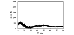
- FIG. 5 shows the X-ray diffraction results of Comparative Example 4.
- the X-ray diffraction pattern shown in FIG. 5 is obtained by removing the background data of the polyimide tape from the measurement results.
- Comparative Example 12 differs from Example 4 in the dew point of the dry room during mixing. In Comparative Example 12, the dew point was -20°C. The other conditions were the same as in Example 4, and the solid electrolyte was measured. The composition, molar ratio, and measurement results of each raw material are listed in Table 2 below.
- LZOC is a mixture of Li2O and ZrCl4 .
- LZSOC is a mixture of Li2SO4 and ZrCl4 .
- LZPOC is a mixture of Li3PO4 and ZrCl4 .
- All-solid-state batteries were also fabricated in a glove box with a dew point of approximately -70°C.
- the all-solid-state battery was manufactured using a pellet manufacturing jig.
- the pellet production jig has a holder made of PEEK (polyetheretherketone) with an inner diameter of 10 mm, and an upper punch and a lower punch with a diameter of 9.99 mm.
- the material of the upper and lower punches is die steel (SKD11 material).
- the lower punch was inserted into the PEEK holder of the pellet production jig, and 50 mg of solid electrolyte was poured onto the lower punch.
- the resin holder was vibrated to level the surface of the solid electrolyte, and then an upper punch was inserted onto the solid electrolyte, and the solid electrolyte was pressed with a load of about 4 KN using a press machine.
- the negative electrode mixture consisted of a negative electrode active material and the above-mentioned solid electrolyte, and lithium titanate (LTO) having an average particle diameter of 6.0 ⁇ m was used as the negative electrode active material.
- LTO lithium titanate
- the positive electrode mixture consisted of a positive electrode active material, carbon as a conductive aid, and the above-mentioned solid electrolyte, and the positive electrode active material used was lithium cobalt oxide (LCO) having an average particle diameter of 7.5 ⁇ m.
- LCO lithium cobalt oxide
- two stainless steel plates with a diameter of 50 mm and a thickness of 5 mm and two Bakelite (registered trademark) plates with a diameter of 50 mm and a thickness of 2 mm were prepared.
- four holes for passing screws were formed in each of the two stainless steel plates and the two Bakelite (registered trademark) plates.
- the electrochemical cell, two stainless steel plates, and two Bakelite (registered trademark) plates are stacked, the holes through which the screws pass are formed so that the two stainless steel plates and the two Bakelite (registered trademark) plates are stacked together. It was provided at a position that overlapped with the electrochemical cell in plan view and did not overlap with the electrochemical cell in plan view.
- the rate characteristics were evaluated using the manufactured all-solid-state battery. The rate characteristics were evaluated from the ratio of the discharge capacity when discharging at a discharge rate of 1C to the discharge capacity at a discharge rate of 0.1C (1C/0.1C rate characteristic). All-solid-state batteries are charged with constant current (CC charging) at a constant current rate of 0.1C in an environment of 25°C until the battery voltage reaches 2.7V, and after reaching 2.7V, a current equivalent to 0.05C is charged. I charged it until it reached (CV charging). Thereafter, the battery was discharged at a constant current at a rate of 0.1C until the battery voltage reached 1.5V (CC discharge), and the discharge capacity at 0.1C was measured. Next, the all-solid-state battery was charged again under the above conditions and discharged at a 1C discharge rate until the battery voltage reached 1.5V, and the discharge capacity at 1C was measured. The measurement results are also summarized in Table 1, Table 2, Table 3, and Table 4.
- FIG. 6 shows the charge/discharge curves of Example 4 and Comparative Examples 3 and 4.
- Example 4 is shown by a dashed line
- Comparative Example 3 is shown by a dotted line
- Comparative Example 4 is shown by a solid line. As shown in FIG. 6, it was confirmed that Example 4 had higher input/output characteristics than Comparative Examples 3 and 4.
- a solid electrolyte with improved ionic conductivity can be obtained.
- Solid electrolyte battery 10 solid electrolyte layer 20 positive electrode 22 positive electrode current collector 24 positive electrode mixture layer 30 negative electrode, 32 Negative electrode current collector 34 Negative electrode mixture layer 40 Power generation element 50 Exterior body 52 Metal foil 54 Resin layer 60, 62 Terminal 100 Solid electrolyte battery
Landscapes
- Chemical & Material Sciences (AREA)
- General Chemical & Material Sciences (AREA)
- Chemical Kinetics & Catalysis (AREA)
- Electrochemistry (AREA)
- Engineering & Computer Science (AREA)
- Manufacturing & Machinery (AREA)
- Materials Engineering (AREA)
- Physics & Mathematics (AREA)
- Condensed Matter Physics & Semiconductors (AREA)
- General Physics & Mathematics (AREA)
- Inorganic Chemistry (AREA)
- Conductive Materials (AREA)
- Secondary Cells (AREA)
Abstract
本発明の固体電解質(10)は、LiaAbEc(SO4)dJeXfHh…(1)を含み、式(1)において、AはLi以外のアルカリ金属とアルカリ土類金属とから選択される少なくとも1種の元素であり、EはAl、Ga、In、Sc、Y、Ti、Zr、Hf、ランタノイドからなる群から選択される少なくとも1種の元素であり、JはOH、BO2、BO3、BO4、B3O6、B4O7、CO3、NO3、AlO2、SiO3、SiO4、Si2O7、Si3O9、Si4O11、Si6O18、PO3、PO4、P2O7、P3O10、SO3、SO5、S2O3、S2O4、S2O5、S2O6、S2O7、S2O8、BF4、PF6、BOB、(COO)2、N、AlCl4、CF3SO3、CH3COO、CF3COO、OOC-(CH2)2-COO、OOC-CH2-COO、OOC-CH(OH)-CH(OH)-COO、OOC-CH(OH)-CH2-COO、C6H5SO3、OOC-CH=CH-COO、OOC-CH=CH-COO、C(OH)(CH2COOH)2COO、AsO4、BiO4、CrO4、MnO4、PtF6、PtCl6、PtBr6、PtI6、SbO4、SeO4、TeO4、HCOO、Oからなる群から選択される少なくとも1つの基であり、 XはF、Cl、Br、Iからなる群から選択される少なくとも1種の元素であり、 0.5≦a<6、0≦b<6、0<c<2、0.1<d≦6.0、0<e≦6.0、0<f≦6.1、0≦h≦0.2を満たし、 Cu-Kαを線源としたX線回折パターンにおいて、回折角2θ=22.3°±1.0°にピークが確認される。
Description
本発明は、固体電解質、固体電解質層及び固体電解質電池に関する。
本願は、2022年3月11日に、日本に出願された特願2022-038447号に基づき優先権を主張し、その内容をここに援用する。
本願は、2022年3月11日に、日本に出願された特願2022-038447号に基づき優先権を主張し、その内容をここに援用する。
近年、エレクトロニクス技術の発達はめざましく、携帯電子機器の小型軽量化、薄型化、多機能化が図られている。それに伴い、電子機器の電源となる電池に対し、小型軽量化、薄型化、信頼性の向上が強く望まれており、電解質として固体電解質を用いる固体電解質電池が注目されている。固体電解質として、酸化物系固体電解質、硫化物系固体電解質、錯体水素化物系固体電解質、ハライド系固体電解質等が知られている。
例えば、非特許文献1には、ハライド系固体電解質であるLi3ScCl6のイオン伝導度が3mS/cmであることが記載され、還元側の電位窓が0.91V(V vs. Li/Li+)であることが記載されている。
Jianwen Liang et al., Journal of American Chemical Society2020, 142, 7012-7022.
ハライド系固体電解質は、酸化物系固体電解質、硫化物系固体電解質、錯体水素化物系固体電解質等よりイオン伝導度が高いと言われている。非特許文献1に記載のLi3ScCl6のイオン伝導度(3mS/cm)は高いが、種々の制限を受け、非特許文献1に記載の特性がそのまま発現しない場合や他の物質を選択せざる得ない場合もある。そのため、同じような構造の固体電解質において、イオン伝導度を相対的に向上させることができる構成が求められている。
本発明は上記問題に鑑みてなされたものであり、イオン伝導性を向上させることができる固体電解質、固体電解質層及び固体電解質電池を提供することを目的とする。
上記課題を解決するため、以下の手段を提供する。
(1)第1の態様にかかる固体電解質は、LiaAbEc(SO4)dJeXfHh…(1)を含む。式(1)において、AはLi以外のアルカリ金属とアルカリ土類金属とから選択される少なくとも1種の元素であり、EはAl、Ga、In、Sc、Y、Ti、Zr、Hf、ランタノイドからなる群から選択される少なくとも1種の元素であり、JはOH、BO2、BO3、BO4、B3O6、B4O7、CO3、NO3、AlO2、SiO3、SiO4、Si2O7、Si3O9、Si4O11、Si6O18、PO3、PO4、P2O7、P3O10、SO3、SO5、S2O3、S2O4、S2O5、S2O6、S2O7、S2O8、BF4、PF6、BOB、(COO)2、N、AlCl4、CF3SO3、CH3COO、CF3COO、OOC-(CH2)2-COO、OOC-CH2-COO、OOC-CH(OH)-CH(OH)-COO、OOC-CH(OH)-CH2-COO、C6H5SO3、OOC-CH=CH-COO、OOC-CH=CH-COO、C(OH)(CH2COOH)2COO、AsO4、BiO4、CrO4、MnO4、PtF6、PtCl6、PtBr6、PtI6、SbO4、SeO4、TeO4、HCOO、Oからなる群から選択される少なくとも1つの基であり、XはF、Cl、Br、Iからなる群から選択される少なくとも1種の元素である。また式(1)は、0.5≦a<6、0≦b<6、0<c<2、0.1<d≦6.0、0<e≦6.0、0<f≦6.1、0≦h≦0.2を満たす。また第1の態様にかかる固体電解質は、Cu-Kαを線源としたX線回折パターンにおいて、回折角2θ=22.3°±1.0°にピークが確認される。
(2)上記態様にかかる固体電解質は、Cu-Kαを線源としたX線回折パターンにおいて、回折角2θ=36.4°±1.0°にピークが確認されてもよい。
(3)上記態様にかかる固体電解質は、X線光電子分光測定において、170±0.5eV及び532±0.5eVにピークが確認されてもよい。
(4)上記態様にかかる固体電解質は、25℃におけるイオン伝導度が1mS/cm以上でもよい。
(5)第2の態様にかかる固体電解質層は、上記態様にかかる固体電解質を含む。
(6)第3の態様にかかる固体電解質電池は、負極と、正極と、前記負極と前記正極との間にあり固体電解質を含む固体電解質層と、を備える。前記負極と前記正極と前記固体電解質層とのうち少なくとも一つ以上は、上記態様にかかる固体電解質を含む。
(7)第4の態様にかかる固体電解質電池は、負極と、正極と、前記負極と前記正極との間にある上記態様にかかる固体電解質層を備える。
上記態様にかかる固体電解質は、イオン伝導性を向上させることができる。
以下、本実施形態について、図を適宜参照しながら詳細に説明する。以下の説明で用いる図面は、本発明の特徴をわかりやすくするために便宜上特徴となる部分を拡大して示している場合があり、各構成要素の寸法比率などは実際とは異なっていることがある。以下の説明において例示される材料、寸法等は一例であって、本発明はそれらに限定されるものではなく、その要旨を変更しない範囲で適宜変更して実施することが可能である。
「固体電解質」
固体電解質は、外部から電場をかけることでイオンを移動させることができる物質である。固体電解質のイオン伝導度が高いと、固体電解質電池におけるイオンの授受がスムーズになり、内部抵抗が小さくなる。
固体電解質は、外部から電場をかけることでイオンを移動させることができる物質である。固体電解質のイオン伝導度が高いと、固体電解質電池におけるイオンの授受がスムーズになり、内部抵抗が小さくなる。
固体電解質は、LiaAbEc(SO4)dJeXfHh…(1)で表されるハライド系固体電解質を含む。固体電解質は、上記式(1)で表される化合物の他、原料粉末起因の材料を含んでもよい。原料粉末起因の物質は、例えば、Li2SO4である。
固体電解質は、粉末(粒子)の状態であってもよいし、粉末を焼結した焼結体の状態でもよい。また固体電解質は、粉末を圧縮して成形した成形体、粉末とバインダーとの混合物を成形した成形体、粉末とバインダーと溶媒とを含む塗料を塗布した後、加熱して溶媒を除去することにより形成した塗膜でもよい。また固体電解質の主構造は、アモルファスでも結晶質でもよい。
式(1)において、Liはリチウムイオンである。aは、0.5≦a<6を満たし、好ましくは2.0≦a≦4.0を満たし、より好ましくは2.5≦a≦3.5をみたす。EがZrまたはHfである場合、aは1.0≦a≦3.0が好ましく、1.5≦a≦2.5がより好ましい。式(1)で表される化合物において、aが0.5≦a<6であれば、化合物中に含まれるLiの含有量が適正となり、固体電解質層10のイオン伝導度の高くなる。
式(1)において、Aは、Li以外のアルカリ金属とアルカリ土類金属とから選択される少なくとも1種の元素である。Aは、Liイオンの一部と置換される。Aは、例えば、Na、Caである。AがNa又はCaであると、固体電解質の還元側の電位窓が広くなる。bは、0≦b<6を満たす。またa+bは、0.5≦a+b<6を満たす。
式(1)において、Eは、必須の成分であり、Al、Ga、In、Sc、Y、Ti、Zr、Hf、ランタノイド(La、Ce、Pr、Nd、Pm、Sm、Eu、Gd、Tb、Dy、Ho、Er、Tm、Yb、Lu)からなる群から選択される少なくとも1種の元素である。Eは、Al、Sc、Y、Zr、Hf、Laを含むことが好ましく、Zr、Yを含むことがより好ましい。Eは、固体電解質のイオン電導度を向上する。cは0<b<2である。Eを含むことによる効果がより効果的に得られるため、cは0.6≦cであることが好ましい。また、Eは、固体電解質の骨格を形成する元素である。cは、c≦1であることがより好ましい。
式(1)において、SO4は硫酸塩である。dは、0.1<d≦6.0を満たし、好ましくは0.2≦d≦4.0を満たし、より好ましくは0.4≦d≦2.5を満たす。固体電解質が硫酸塩を含むと、固体電解質の還元側の電位窓が広くなり、還元されにくくなる。
式(1)において、Jは、例えば、OH、BO2、BO3、BO4、B3O6、B4O7、CO3、NO3、AlO2、SiO3、SiO4、Si2O7、Si3O9、Si4O11、Si6O18、PO3、PO4、P2O7、P3O10、SO3、SO5、S2O3、S2O4、S2O5、S2O6、S2O7、S2O8、BF4、PF6、BOB(ビスオキサレートボラート)、(COO)2、N、AlCl4、CF3SO3、CH3COO、CF3COO、OOC-(CH2)2-COO(コハク酸塩)、OOC-CH2-COO(マロン酸塩)、OOC-CH(OH)-CH(OH)-COO(酒石酸塩)、OOC-CH(OH)-CH2-COO(リンゴ酸塩)、C6H5SO3(ベンゼンスルホン酸塩)、OOC-CH=CH-COO(フマル酸塩)、OOC-CH=CH-COO(マレイン酸塩)、C(OH)(CH2COOH)2COO(クエン酸塩)、AsO4、BiO4、CrO4、MnO4、PtF6、PtCl6、PtBr6、PtI6、SbO4、SeO4、TeO4、HCOO、Oからなる群から選択される少なくとも1つの基である。Jは、OH、SO4、CH3COO、CF3COO、HCOO、Oからなる群から選択される少なくとも1つの基であることが好ましい。Jは、硫酸塩の一部と置換される。
eは0≦e≦6を満たす。eは、Jを含むことによる還元側の電位窓が広くなる効果がより顕著となるため、0.5≦eであることが好ましい。eは、Jの含有量が多すぎることに起因する固体電解質のイオン伝導度の低下が生じないように、e≦3であることが好ましい。またd+eは、0.1<d≦6.0を満たす。
XはF、Cl、Br、Iからなる群から選択される少なくとも1種以上である。Xは、固体電解質のイオン電導度を高めるために、Cl、Br、Iからなる群から選択される少なくとも1種以上であることが好ましく、Brおよび/またはIを含むことが好ましく、特にIを含むことが好ましい。XがFを含む場合、Xはイオン伝導度の高い固体電解質となるため、Fと、Cl、Br、Iからなる群から選択される2種以上とを含むことが好ましい。
XがFであると、イオン伝導度が十分に高く、かつ耐酸化性に優れる固体電解質となる。XがClであると、イオン伝導度が高く、かつ耐酸化性および耐還元性のバランスが良い固体電解質となる。XがBrであると、イオン伝導度十分に高く、かつ耐酸化性および耐還元性のバランスが良い固体電解質となる。XがIであると、イオン伝導度の高い固体電解質となる。
fは、0<f≦6.1を満たす。dは1≦fであることが好ましい。fが1≦dであると、固体電解質を加圧成形してペレット状に成形する場合に、ペレットの強度が高くなる。また、fが1≦fであると、固体電解質のイオン伝導度が高くなる。また、fは、Xの含有量が多すぎることによって硫酸塩が不足して、固体電解質の電位窓が狭くならないように、f≦5であることが好ましい。
式(1)において、Hは水素である。hは、0≦h≦0.2を満たす。
固体電解質は、例えば、Li2ZrSO4Cl4、Li3YSO4Cl4、Li3ScSO4Cl4、Li3InSO4Cl4である。
図1は、本実施形態に係る固体電解質をX線回折(XRD)した結果である。図1における縦軸は強度であり、横軸は2θである。X線回折は、Cu-α線源を用いて行った。
図1に示すX線回折パターンは、測定結果からポリイミドテープのバックグラウンドデータを除去したものである。図1は、後述する実施例4のX線回折結果である。図1に示すように、本実施形態に係る固体電解質は、Cu-Kαを線源としたX線回折パターンにおいて、回折角2θ=22.3°±1.0°にピークが確認される。また本実施形態に係る固体電解質は、Cu-Kαを線源としたX線回折パターンにおいて、回折角2θ=36.4°±1.0°にもピークが確認されてもよい。
図1に示すX線回折パターンは、測定結果からポリイミドテープのバックグラウンドデータを除去したものである。図1は、後述する実施例4のX線回折結果である。図1に示すように、本実施形態に係る固体電解質は、Cu-Kαを線源としたX線回折パターンにおいて、回折角2θ=22.3°±1.0°にピークが確認される。また本実施形態に係る固体電解質は、Cu-Kαを線源としたX線回折パターンにおいて、回折角2θ=36.4°±1.0°にもピークが確認されてもよい。
これらのピークは、式(1)の化合物を作製する際に用いられる原料であるLi2SO4由来のピークであると考えられる。回折角2θ=22.3°±1.0°に生じるピークは、Li2SO4のX線回折パターンにおいて最も大きな強度を示す第1ピークである。
回折角2θ=36.4°±1.0°に生じるピークは、Li2SO4のX線回折パターンにおいて比較的大きな強度を示すピークである。
回折角2θ=36.4°±1.0°に生じるピークは、Li2SO4のX線回折パターンにおいて比較的大きな強度を示すピークである。
これらのピークは、原料同士を十分に反応させると消失するピークである。図2は、式(1)の化合物を含む固体電解質のX線回折結果である。図2に示すX線回折パターンは、測定した生データであり、ポリイミドテープのバックグラウンドデータを除去していないものである。紙面手前から奥に進むほど、原料同士の反応を進めたものである。図2に示すように、回折角2θ=22.3°±1.0°に生じるピーク及び回折角2θ=36.4°±1.0°に生じるピークは、原料同士の反応が進行するにつれ、消失している。したがって、本実施形態に係る固体電解質でこれらのピークが確認されるということは、未反応の原料粉末(LiSO4)の一部が残存していると考えられる。
図3A、Bは、本実施形態に係る固体電解質のX線光電子分光測定結果を示すグラフのうち、ピークが発生する範囲を拡大したものである。本実施形態に係る固体電解質は、例えば、170±0.5eV及び532±0.5eVにピークが確認される。170±0.5eVのピークは、硫黄と酸素との結びついた構造がある場合に確認される硫黄のS2p由来のピークであり、532±0.5eVのピークは、硫黄と酸素との結びついた構造がある場合に確認される酸素のO1s由来のピークである。すなわち、固体電解質にはSO4の構造を有する部分があるといえ、当該構造は未反応の原料粉末(LiSO4)に由来するものと考えられる。
本実施形態に係る固体電解質は、上述のように、X線回折で特定のピークが確認され、イオン伝導度が高い。例えば、本実施形態に係る固体電解質のイオン伝導度は、1mS/cm以上である。固体電解質がX線回折で特定のピークを有するとイオン伝導度が高まる理由は明確ではないが、残存する結晶質のLiSO4が固体電解質内に、Liイオンが伝導できる流路を有する微細構造を形成する起点となるためではないかと考えられる。
「固体電解質電池」
図4は、本実施形態にかかる固体電解質電池100の断面模式図である。図4に示す固体電解質電池100は、発電素子40と外装体50とを備える。外装体50は、発電素子40の周囲を被覆する。発電素子40は、接続された一対の端子60、62によって外部と接続される。図1では、積層型の電池を示したが、巻回型の電池でもよい。固体電解質電池100は、例えば、ラミネート電池、角型電池、円筒型電池、コイン型電池、ボタン型電池等に用いられる。
図4は、本実施形態にかかる固体電解質電池100の断面模式図である。図4に示す固体電解質電池100は、発電素子40と外装体50とを備える。外装体50は、発電素子40の周囲を被覆する。発電素子40は、接続された一対の端子60、62によって外部と接続される。図1では、積層型の電池を示したが、巻回型の電池でもよい。固体電解質電池100は、例えば、ラミネート電池、角型電池、円筒型電池、コイン型電池、ボタン型電池等に用いられる。
<発電素子>
発電素子40は、固体電解質層10と正極20と負極30とを備える。発電素子40は、正極20と負極30の間で固体電解質層10を介したイオンの授受及び外部回路を介した電子の授受により充電または放電する。
発電素子40は、固体電解質層10と正極20と負極30とを備える。発電素子40は、正極20と負極30の間で固体電解質層10を介したイオンの授受及び外部回路を介した電子の授受により充電または放電する。
(固体電解質層)
固体電解質層10は、正極20と負極30とに挟まれる。固体電解質層10は、外部から印加された電圧によってイオンを移動させることができる固体電解質を含む。例えば、固体電解質は、リチウムイオンを伝導し、電子の移動を阻害する。
固体電解質層10は、正極20と負極30とに挟まれる。固体電解質層10は、外部から印加された電圧によってイオンを移動させることができる固体電解質を含む。例えば、固体電解質は、リチウムイオンを伝導し、電子の移動を阻害する。
固体電解質層10は、例えば、ハライド系固体電解質である。固体電解質層10は、例えば、上述の固体電解質を含む。正極20又は負極30に上述の固体電解質が含有されている場合は、固体電解質層10に含まれる固体電解質は上述の物で無くてもよい。
(正極)
図4に示すように、正極20は、板状(箔状)の正極集電体22と正極合剤層24とを有する。正極合剤層24は、正極集電体22の少なくとも一面に接する。
図4に示すように、正極20は、板状(箔状)の正極集電体22と正極合剤層24とを有する。正極合剤層24は、正極集電体22の少なくとも一面に接する。
正極集電体22は、充電時の酸化に耐え腐食しにくい電子伝導性の材料であれば良い。
正極集電体22は、例えば、アルミニウム、ステンレス、ニッケル、チタンなどの金属、伝導性樹脂等である。正極集電体22は、粉体、箔、パンチング、エクスパンドの各形態であっても良い。
正極集電体22は、例えば、アルミニウム、ステンレス、ニッケル、チタンなどの金属、伝導性樹脂等である。正極集電体22は、粉体、箔、パンチング、エクスパンドの各形態であっても良い。
正極合剤層24は、正極活物質を含み、必要に応じて、固体電解質、バインダーおよび導電助剤を含む。
正極活物質は、リチウムイオンの吸蔵・放出、挿入・脱離(インターカレーション・デインターカレーション)を可逆的に進行させることが可能であれば特に限定されず、公知の固体電解質電池に用いられている正極活物質を使用できる。正極活物質としては、例えば、リチウム含有金属酸化物、リチウム含有金属リン酸化物などが挙げられる。
リチウム含有金属酸化物は、例えば、コバルト酸リチウム(LiCoO2)、ニッケル酸リチウム(LiNiO2)、リチウムマンガンスピネル(LiMn2O4)、及び、一般式:LiNixCoyMnzO2(x+y+z=1)で表される複合金属酸化物、リチウムバナジウム化合物(LiVOPO4、Li3V2(PO4)3)、オリビン型LiMPO4(ただし、Mは、Co、Ni、Mn、Feから選択される少なくとも1種を示す)、チタン酸リチウム(Li4Ti5O12)等である。
また正極活物質は、リチウムを含有していないものでもよい。このような正極活物質としては、リチウム非含有金属酸化物(MnO2、V2O5など)、リチウム非含有金属硫化物(MoS2など)、リチウム非含有フッ化物(FeF3、VF3など)などが挙げられる。リチウムを含有していない正極活物質を用いる場合、あらかじめ負極にリチウムイオンをドープしておく、またはリチウムイオンを含有する負極を用いる。
正極20に含まれる固体電解質は、例えば、上述の固体電解質である。正極20に含まれる固体電解質は、上述の固体電解質以外のハライド系固体電解質でもよい。
正極合剤層24における固体電解質の含有率は、特に限定されないが、正極活物質、固体電解質、導電助剤及びバインダーの質量の総和を基準にして、1質量%~50質量%であることが好ましく、5質量%~30質量%であることがより好ましい。
バインダーは、正極合剤層24内において正極活物質と固体電解質と導電助剤とを相互に結合するとともに、正極合剤層24と正極集電体22とを、強固に接着する。正極合剤層24は、バインダーを含むことが好ましい。バインダーは、耐酸化性を有し、接着性が良いことが好ましい。
正極合剤層24に用いられるバインダーとしては、ポリフッ化ビニリデン(PVDF)またはそのコポリマー、ポリテトラフルオロエチレン(PTFE)、ポリアミド(PA)、ポリイミド(PI)、ポリアミドイミド(PAI)、ポリベンゾイミダゾール(PBI)、ポリエーテルスルホン(PES)、ポリアクリル酸(PA)及びその共重合体、ポリアクリル酸(PA)及びその共重合体の金属イオン架橋体、無水マレイン酸をグラフト化したポリプロピレン(PP)、無水マレイン酸をグラフト化したポリエチレン(PE)、または、これらの混合物などが挙げられる。これらの中でも、バインダーとしては、特にPVDFを用いることが好ましい。
正極合剤層24におけるバインダーの含有率は、特に限定されないが、正極活物質、固体電解質、導電助剤及びバインダーの質量の総和を基準にして、1質量%~15質量%であることが好ましく、3質量%~5質量%であることがより好ましい。バインダー量が少な過ぎると、十分な接着強度の正極20を形成できなくなる傾向がある。逆にバインダー量が多過ぎると、一般的なバインダーは電気化学的に不活性なので放電容量に寄与せず、十分な体積または質量エネルギー密度を得ることが困難となる傾向がある。
導電助剤は、正極合剤層24の電子伝導性を良好にする。導電助剤は、公知のものを用いることができる。導電助剤は、例えば、カーボンブラック、黒鉛、カーボンナノチューブ、グラフェンなどの炭素材料、アルミニウム、銅、ニッケル、ステンレス、鉄、アモルファス金属などの金属、ITOなどの伝導性酸化物、またはこれらの混合物である。導電助剤は、粉体、繊維の各形態であっても良い。
正極合剤層24における導電助剤の含有率は、特に限定されない。導電助剤を添加する場合には通常、正極活物質、固体電解質、導電助剤及びバインダーの質量の総和を基準にして、導電助剤の質量比は、0.5質量%~20質量%であることが好ましく、1質量%~5質量%とすることがより好ましい。
(負極)
図4に示すように、負極30は、負極集電体32と負極合剤層34とを有する。負極合剤層34は、負極集電体32に接する。
図4に示すように、負極30は、負極集電体32と負極合剤層34とを有する。負極合剤層34は、負極集電体32に接する。
負極集電体32は、電子伝導性を有すれば良い。負極集電体32は、例えば、銅、アルミニウム、ニッケル、ステンレス、鉄などの金属、または、伝導性樹脂等である。負極集電体32は、粉体、箔、パンチング、エクスパンドの各形態であっても良い。
負極合剤層34は、負極活物質を含み、必要に応じて、固体電解質、バインダーおよび導電助剤を含む。
負極活物質は、リチウムイオンの吸蔵及び放出、リチウムイオンの挿入及び脱離を可逆的に進行させることができればよく、特に限定されない。負極活物質には、公知の固体電解質電池に用いられている負極活物質を使用できる。
負極活物質は、例えば、天然黒鉛、人造黒鉛、メソカーボンマイクロビーズ、メソカーボンファイバー(MCF)、コークス類、ガラス状炭素、有機化合物焼成体などの炭素材料、Si、SiOx、Sn、アルミニウムなどのリチウムと化合できる金属、これらの合金、これら金属と炭素材料との複合材料、チタン酸リチウム(Li4Ti5O12)、SnO2などの酸化物、金属リチウム等である。負極活物質は、天然黒鉛が好ましい。
負極30に含まれる固体電解質は、例えば、上述の固体電解質である。負極30に含まれる固体電解質は、上述の固体電解質以外のハライド系固体電解質でもよい。
負極30に含まれるバインダー及び導電助剤は、正極20に含まれるバインダー及び導電助剤と同様である。
<外装体>
外装体50は、その内部に発電素子40を収納する。外装体50は、外部から内部への水分などの侵入を防ぐ。外装体50は、例えば図4に示すように、金属箔52と、金属箔52の各面に積層された樹脂層54と、を有する。外装体50は、金属箔52を樹脂層54で両側からコーティングした金属ラミネートフィルムである。
外装体50は、その内部に発電素子40を収納する。外装体50は、外部から内部への水分などの侵入を防ぐ。外装体50は、例えば図4に示すように、金属箔52と、金属箔52の各面に積層された樹脂層54と、を有する。外装体50は、金属箔52を樹脂層54で両側からコーティングした金属ラミネートフィルムである。
金属箔52は、例えばアルミ箔、ステンレス箔である。樹脂層54は、例えば、ポリプロピレン等の樹脂膜を利用できる。樹脂層54を構成する材料は、内側と外側とで異なっていてもよい。例えば、外側の材料としては融点の高い高分子、例えば、ポリエチレンテレフタレート(PET)、ポリアミド(PA)等を用い、内側の材料としてはポリエチレン(PE)、ポリプロピレン(PP)等を用いることができる。
<端子>
端子60、62は、それぞれ正極20と負極30とに接続されている。正極20に接続された端子60は正極端子であり、負極30に接続された端子62は負極端子である。端子60、62は、外部との電気的接続を担う。端子60、62は、アルミニウム、ニッケル、銅等の導電材料から形成されている。接続方法は、溶接でもネジ止めでもよい。端子60、62は短絡を防ぐために、絶縁テープで保護することが好ましい。
端子60、62は、それぞれ正極20と負極30とに接続されている。正極20に接続された端子60は正極端子であり、負極30に接続された端子62は負極端子である。端子60、62は、外部との電気的接続を担う。端子60、62は、アルミニウム、ニッケル、銅等の導電材料から形成されている。接続方法は、溶接でもネジ止めでもよい。端子60、62は短絡を防ぐために、絶縁テープで保護することが好ましい。
[固体電解質電池の製造方法]
次に、本実施形態にかかる固体電解質電池の製造方法について説明する。まず固体電解質を準備する。固体電解質は、例えば、所定のモル比で所定の元素を含む原料粉末を混合し、メカノケミカル反応をさせる方法により製造できる。メカノケミカル反応を行う際に、未反応の原料が固体電解質内に残存するように調整する。具体的には、遊星型ボールミルの自転回転数、公転回転数、合成時間、投入時の原料粉末の状態を変えることで、原料の未反応成分を残存させることができる。
次に、本実施形態にかかる固体電解質電池の製造方法について説明する。まず固体電解質を準備する。固体電解質は、例えば、所定のモル比で所定の元素を含む原料粉末を混合し、メカノケミカル反応をさせる方法により製造できる。メカノケミカル反応を行う際に、未反応の原料が固体電解質内に残存するように調整する。具体的には、遊星型ボールミルの自転回転数、公転回転数、合成時間、投入時の原料粉末の状態を変えることで、原料の未反応成分を残存させることができる。
原材粉末中にハロゲン化物原料が含まれている場合、ハロゲン化物原料は、温度を上げると蒸発しやすい。このため、焼結する際の雰囲気中にハロゲンガスを共存させて、ハロゲンを補ってもよい。また、原材粉末中にハロゲン化物原料が含まれている場合、密閉性の高い型を用いてホットプレス法により焼結しても良い。この場合、型の密閉性が高いため、焼結によるハロゲン化物原料の蒸発を抑制できる。このようにして焼結することにより、所定の組成を有する化合物からなる焼結体の状態の固体電解質が得られる。
次いで、正極20を準備する。正極は、正極集電体22上に、正極活物質を含むペーストを塗布し、乾燥させて正極合剤層24を形成することにより製造される。正極活物質を含むペーストに上記の固体電解質を添加してもよい。
次いで、負極30を準備する。負極は、負極集電体32上に、負極活物質を含むペーストを塗布し、乾燥させて負極合剤層34を形成することにより製造される。負極活物質を含むペーストに上記の固体電解質を添加してもよい。
発電素子40は、例えば、粉末成型法を用いて作製できる。正極20の上に、穴部を有するガイドを設置し、ガイド内に固体電解質を充填する。その後、固体電解質の表面をならし、固体電解質の上に負極30を重ねる。このことにより、正極20と負極30との間に固体電解質が挟まれる。その後、正極20および負極30に圧力を加えることで、固体電解質を加圧成形する。加圧成形されることにより、正極20と固体電解質層10と負極30が、この順に積層された積層体が得られる。
次に、積層体を形成している正極20の正極集電体22および負極30の負極集電体32に、それぞれ公知の方法により外部端子を溶接し、正極集電体22または負極集電体32と外部端子とを電気的に接続する。その後、外部端子と接続された積層体を外装体50に収納し、外装体50の開口部をヒートシールすることにより密封する。以上の工程により、本実施形態の固体電解質電池100が得られる。
本実施形態に係る固体電解質電池100は、上述の固体電解質を含むため、Liイオンの伝導がスムーズであり、内部抵抗が低い。
以上、本発明の実施形態について図面を参照して詳述したが、各実施形態における各構成及びそれらの組み合わせ等は一例であり、本発明の趣旨から逸脱しない範囲内で、構成の付加、省略、置換、及びその他の変更が可能である。
「実施例1」
(固体電解質の作製)
露点約-75℃のグローブボックス内において、塩化ジルコニウム(ZrCl4)と硫酸リチウム(Li2SO4)とをそれぞれ、モル比で1:8の割合になるように原料粉末を秤量した。まず混合前のLi2SO4を、遊星型ボールミルを用いて1時間粉砕した。粉砕の際の回転数は300rpmとした。次いで、あらかじめジルコニアボールを入れている遊星型ボールミル用のジルコニア製密閉容器に、原料粉末を投入した。次に密閉容器に蓋をし、蓋を容器本体にねじ止めし、さらに蓋と容器の間をポリイミドテープでシールした。ポリイミドテープは水分を遮断する効果がある。次に、ジルコニア製密閉容器を遊星型ボールミルにセットした。自転回転数200rpm、公転回転数200rpmとし、自転の回転方向と公転の回転方向とを逆方向として原料粉末を混合し、2時間メカノケミカル反応させ、固体電解質(Li4Zr0.25(SO4)2Cl)を生成させた。
遊星型ボールミルは、通常雰囲気(大気)中に設置している。遊星型ボールミル用のジルコニア製密閉容器はねじ止めされ、さらにポリイミドテープでシールしてあり、遊星型ボールミルにジルコニア製密閉容器をセットすると、ジルコニア製密閉容器が固く押圧固定される構造であるため、通常雰囲気であっても、ジルコニア製密閉容器内には大気から水分の混入は殆どないと考えられる。
[XRD測定]
アルゴンガスを循環している露点約-70℃のグローブボックス内で、作製した固体電解質をXRD測定用ホルダーに充填した。その後充填面を覆うように、防湿のためのポリイミドテープ(70℃で16時間真空乾燥させたもの)を張り付け封止し、XRD測定試料を準備した。次いで大気中に取り出し、X線回折装置(パナリティカル社製 X‘PertPro)を用いてXRD測定を行った。X線源は、Cu-Kα線(測定波長=0.799407Å)を用いた。
アルゴンガスを循環している露点約-70℃のグローブボックス内で、作製した固体電解質をXRD測定用ホルダーに充填した。その後充填面を覆うように、防湿のためのポリイミドテープ(70℃で16時間真空乾燥させたもの)を張り付け封止し、XRD測定試料を準備した。次いで大気中に取り出し、X線回折装置(パナリティカル社製 X‘PertPro)を用いてXRD測定を行った。X線源は、Cu-Kα線(測定波長=0.799407Å)を用いた。
また、上記XRD測定と同様の条件で、防湿のために用いたポリイミドテープのみをXRD測定用ホルダーに張り付け、バックグラウンド測定を行った。作製された固体電解質のX線回折パターンは、回折角2θ=22.3°±1.0°及び回折角2θ=36.4°±1.0°にピークを有していた。
[XPS測定]
またX線光電子分光測定も行った。アルゴンガスを循環している露点約-70℃のグローブボックス内で、サンプリングを行い、大気非暴露状態でXPS測定装置まで搬送した。XPS測定は、PHI社製のQuantera2を用いて測定した。その結果、作製された固体電解質は、170±0.5eV及び532±0.5eVにピークが確認された。
またX線光電子分光測定も行った。アルゴンガスを循環している露点約-70℃のグローブボックス内で、サンプリングを行い、大気非暴露状態でXPS測定装置まで搬送した。XPS測定は、PHI社製のQuantera2を用いて測定した。その結果、作製された固体電解質は、170±0.5eV及び532±0.5eVにピークが確認された。
[イオン伝導度の測定]
次いで、アルゴンガスを循環している露点約-70℃のグローブボックス内で、得られた固体電解質の粉末を加圧成形用ダイスに充填し、約30KNの加重で加圧成形し、イオン伝導度の測定セルを作製した。
次いで、アルゴンガスを循環している露点約-70℃のグローブボックス内で、得られた固体電解質の粉末を加圧成形用ダイスに充填し、約30KNの加重で加圧成形し、イオン伝導度の測定セルを作製した。
加圧成型用ダイスは、直径10mmのPEEK(ポリエーテルエーテルケトン)製円筒、SKD11材の直径9.99mmの上パンチ及び下パンチから構成される。
その後、4か所にねじ穴を有する直径50mm、厚み5mmのステンレス製円板及びテフロン(商標登録)製円板を用意し、次のように加圧成型ダイスをセットした。ステンレス円板/テフロン(商標登録)円板/加圧成型後ダイス/テフロン(商標登録)円板/ステンレス円板の順序で積載し、4か所のネジを約3N・mのトルクで締めた。また、上下パンチの側面に設けたネジ穴にネジを差し込み、外部接続端子とした。
外部接続端子を、周波数応答アナライザを搭載したポテンシオスタット(プリンストン・アプライド・リサーチ社製VersaSTAT3)に接続し、インピーダンス測定法を用いて、イオン伝導度の測定を行った。測定周波数範囲1MHz~0.1Hz、振幅10mV、温度25℃において測定した。実施例1の固体電解質のイオン伝導度は、1.1×10⁻³S/cmであった。
「実施例2~8」
実施例2~8は、原料粉末の材料及びモル比を変えた点が実施例1と異なる。実施例2~8でも実施例1と同様に、固体電解質の測定を行った。各原料の構成、モル比、測定結果を、下記の表1に記載した。
実施例2~8は、原料粉末の材料及びモル比を変えた点が実施例1と異なる。実施例2~8でも実施例1と同様に、固体電解質の測定を行った。各原料の構成、モル比、測定結果を、下記の表1に記載した。
「実施例9~21」
実施例9~21は、原料粉末の材料及びモル比を変え、固体電解質の製造条件を変更した点が実施例1と異なる。実施例9~21でも実施例1と同様に、固体電解質の測定を行った。
実施例9~21は、原料粉末の材料及びモル比を変え、固体電解質の製造条件を変更した点が実施例1と異なる。実施例9~21でも実施例1と同様に、固体電解質の測定を行った。
実施例9~21は、以下のような手順で作製した。まず、露点約-75℃のグローブボックス内において、塩化ジルコニウム(ZrCl4)と硫酸リチウム(Li2SO4)とその他原料とをそれぞれ、所定のモル比になるように秤量した。次いで、混合前のLi2SO4を、遊星型ボールミルを用いて回転数300rpmで1時間粉砕した後に、ZrCl4を加えてさらに回転数200rpmで1時間粉砕した。次いで、あらかじめジルコニアボールを入れている遊星型ボールミル用のジルコニア製密閉容器に、粉砕後の試料と、その他原料とを投入した。そして、自転回転数200rpm、公転回転数200rpmとし、自転の回転方向と公転の回転方向とを逆方向として、所定時間メカノケミカル反応させ、所望の固体電解質を生成させた。
実施例9~21でも実施例1と同様に、固体電解質の測定を行った。各原料の構成、モル比、測定結果を下記の表1に記載した。
「実施例22~25」
実施例22~25は、原料粉末の材料及びモル比を変え、固体電解質の製造条件を変更した点が実施例1と異なる。実施例22~25でも実施例1と同様に、固体電解質の測定を行った。
実施例22~25は、原料粉末の材料及びモル比を変え、固体電解質の製造条件を変更した点が実施例1と異なる。実施例22~25でも実施例1と同様に、固体電解質の測定を行った。
実施例22~25は、以下のような手順で作製した。まず、露点約-75℃のグローブボックス内において、Li2OとZrCl4とLi2SO4と、をそれぞれ、所定のモル比になるように秤量した。まずLi2SO4は、混合前に回転数200rpmで1時間粉砕した。次いで、Li2OとZrCl4とを回転数300rpmで48時間混合した後に、Li2SO4を加えて所定時間メカノケミカル反応させ、所望の固体電解質を生成させた。
実施例22~25でも実施例1と同様に、固体電解質の測定を行った。各原料の構成、モル比、測定結果を下記の表2に記載した。
「実施例26」
実施例26は、原料粉末の材料及びモル比を変え、固体電解質の製造条件を変更した点が実施例1と異なる。実施例26でも実施例1と同様に、固体電解質の測定を行った。
実施例26は、原料粉末の材料及びモル比を変え、固体電解質の製造条件を変更した点が実施例1と異なる。実施例26でも実施例1と同様に、固体電解質の測定を行った。
まず、露点約-75℃のグローブボックス内において、Li3PO4とZrCl4とLi2SO4と、をそれぞれ、所定のモル比になるように秤量した。まずLi2SO4は、混合前に回転数200rpmで1時間粉砕した。次いで、Li3PO4とZrCl4とを回転数300rpmで24時間混合した後に、Li2SO4を加えて所定時間メカノケミカル反応させ、所望の固体電解質を生成させた。
実施例26でも実施例1と同様に、固体電解質の測定を行った。各原料の構成、モル比、測定結果を下記の表2に記載した。
「実施例27~29」
実施例27~29は、原料粉末の材料及びモル比を変え、固体電解質の製造条件を変更した点が実施例1と異なる。実施例27~29でも実施例1と同様に、固体電解質の測定を行った。
実施例27~29は、原料粉末の材料及びモル比を変え、固体電解質の製造条件を変更した点が実施例1と異なる。実施例27~29でも実施例1と同様に、固体電解質の測定を行った。
まず、露点約-75℃のグローブボックス内において、Li2OとLiXとをモル比2:1で混合した。混合は、上述の遊星型ボールミルを用いて、回転数300rpmで48時間混合した。次いで、実施例4で合成したLZSOCを追加し、回転数200rpmで所定時間メカノケミカル反応させ、所望の固体電解質を生成させた。
実施例27~29でも実施例1と同様に、固体電解質の測定を行った。各原料の構成、モル比、測定結果を下記の表2に記載した。
「実施例30、31」
実施例30、31は、混合時のドライルームの露点が実施例4と異なる。実施例30は、露点-40℃とし、実施例31は露点-60℃とした。その他の条件は、実施例4と同じとして、固体電解質の測定を行った。各原料の構成、モル比、測定結果を下記の表2に記載した。
実施例30、31は、混合時のドライルームの露点が実施例4と異なる。実施例30は、露点-40℃とし、実施例31は露点-60℃とした。その他の条件は、実施例4と同じとして、固体電解質の測定を行った。各原料の構成、モル比、測定結果を下記の表2に記載した。
「実施例32~34」
実施例32~34は、原料粉末の材料及びモル比を変え、固体電解質の製造条件を変更した点が実施例1と異なる。実施例32~34でも実施例1と同様に、固体電解質の測定を行った。
実施例32~34は、原料粉末の材料及びモル比を変え、固体電解質の製造条件を変更した点が実施例1と異なる。実施例32~34でも実施例1と同様に、固体電解質の測定を行った。
まず、露点約-75℃のグローブボックス内において、ZrCl4とLiXとを所定のモル比で混合した。混合は、上述の遊星型ボールミルを用いて、回転数300rpmで24時間混合した。次いで、実施例4で合成したLZSOCを追加し、回転数200rpmで所定時間メカノケミカル反応させ、所望の固体電解質を生成させた。
実施例32~34でも実施例1と同様に、固体電解質の測定を行った。各原料の構成、モル比、測定結果を、下記の表3及び表4に記載した。
「実施例35~45」
実施例35~45は、原料粉末の材料及びモル比を変え、固体電解質の製造条件を変更した点が実施例1と異なる。実施例35~45でも実施例1と同様に、固体電解質の測定を行った。
実施例35~45は、原料粉末の材料及びモル比を変え、固体電解質の製造条件を変更した点が実施例1と異なる。実施例35~45でも実施例1と同様に、固体電解質の測定を行った。
まず、露点約-75℃のグローブボックス内において、ZrCl4、LiClとLiXとを所定のモル比で混合した。混合は、上述の遊星型ボールミルを用いて、回転数300rpmで24時間混合した。次いで、実施例4で合成したLZSOCを追加し、回転数200rpmで所定時間メカノケミカル反応させ、所望の固体電解質を生成させた。
実施例35~45でも実施例1と同様に、固体電解質の測定を行った。各原料の構成、モル比、測定結果を、下記の表3及び表4に記載した。
「比較例1~11」
比較例1~11は、原料粉末の材料及びモル比を変え、固体電解質の製造条件を変更した点が実施例1と異なる。比較例1~11でも実施例1と同様に、固体電解質の測定を行った。
比較例1~11は、原料粉末の材料及びモル比を変え、固体電解質の製造条件を変更した点が実施例1と異なる。比較例1~11でも実施例1と同様に、固体電解質の測定を行った。
比較例1~11に係る固体電解質の製造方法は、メカノケミカル反応時の遊星型ボールミの自転回転数を300rpm、公転回転数を300rpmとし、Li2SO4を混合前に粉砕せずに用いた点、及び、メカノケミカル反応の反応時間(原料粉末の混合時間)が、実施例1に係る固体電解質の製造方法と異なる。
比較例1~11でも実施例1と同様に、固体電解質の測定を行った。各原料の構成、モル比、測定結果を下記の表2に記載した。また図5に比較例4のX線回折結果を示す。比較例4では、回折角2θ=22.3°±1.0°及び回折角2θ=36.4°±1.0°にピークが確認されなかった。図5に示すX線回折パターンは、測定結果からポリイミドテープのバックグラウンドデータを除去したものである。
「比較例12」
比較例12は、混合時のドライルームの露点が実施例4と異なる。比較例12は、露点-20℃とした。その他の条件は、実施例4と同じとして、固体電解質の測定を行った。各原料の構成、モル比、測定結果を下記の表2に記載した。
比較例12は、混合時のドライルームの露点が実施例4と異なる。比較例12は、露点-20℃とした。その他の条件は、実施例4と同じとして、固体電解質の測定を行った。各原料の構成、モル比、測定結果を下記の表2に記載した。


なお、上記の表1及び表2において、LZOCは、Li2OとZrCl4との混合物である。LZSOCは、Li2SO4とZrCl4との混合物である。LZPOCは、Li3PO4とZrCl4との混合物である。またXRDの列における「A」はピークが確認されたことを示し、「B」はピークが確認されなかったことを示す。XPS分析では、いずれの実施例及び比較例においても、170±0.5eV及び532±0.5eVにピークが確認された。
(全固体電池の作製)
全固体電池も、露点約-70℃のグローブボックス内で作製した。全固体電池は、ペレット作製治具を用いて作製した。ペレット作製治具は、内径10mmのPEEK(ポリエーテルエーテルケトン)製ホルダーと、直径9.99mmの上パンチおよび下パンチとを有する。上下パンチの材質はダイス鋼(SKD11材)である。
全固体電池も、露点約-70℃のグローブボックス内で作製した。全固体電池は、ペレット作製治具を用いて作製した。ペレット作製治具は、内径10mmのPEEK(ポリエーテルエーテルケトン)製ホルダーと、直径9.99mmの上パンチおよび下パンチとを有する。上下パンチの材質はダイス鋼(SKD11材)である。
ペレット作製治具のPEEK製ホルダーに下パンチを挿入し、下パンチの上に固体電解質を50mg投入した。次いで、樹脂ホルダーを振動させ、固体電解質の表面を均した後、固体電解質の上に上パンチを挿入して、プレス機を用いて約4KNの加重でプレスした。
次に、下パンチを抜いて、固体電解質の上に、負極合剤を10mg投入した。次いで、PEEK製ホルダーを振動させ、負極合剤の表面を均した後、負極合剤の上に下パンチを挿入して、プレス機を用いて3KNの加重でプレスした。負極合剤は、負極活物質と上述の固体電解質とからなり、負極活物質は、平均粒子径が6.0μmのチタン酸リチウム(LTО)を用いた。次に、上パンチを外して、固体電解質層の上に正極合剤を10mg投入した。次いで、PEEK製ホルダーを振動させ、正極合剤の表面を均した後、正極合剤の上に上パンチを挿入して、プレス機を用いて3KNの加重でプレスした。正極合剤は、正極活物質、導電助剤のカーボンと上述の固体電解質とからなり、正極活物質は、平均粒子径が7.5μmのコバルト酸リチウム(LCО)を用いた。こうして、負極合剤層、固体電解質層、正極合剤層が順に積層された全固体電池を作製した。
また、直径50mm、厚み5mmのステンレス鋼板2枚と、直径50mm、厚み2mmのベークライト(登録商標)板2枚とを準備した。次いで、2枚のステンレス鋼板および2枚のベークライト(登録商標)板に、ネジを通す穴をそれぞれ4つずつ設けた。ネジを通す穴は、電気化学セルと、2枚のステンレス鋼板および2枚のベークライト(登録商標)板とを積層したときに、2枚のステンレス鋼板と2枚のベークライト(登録商標)板とが平面視で重なり、かつ電気化学セルと平面視で重ならない位置に設けた。
その後、ステンレス鋼板、ベークライト(登録商標)板、全固体電池、ベークライト(登録商標)板、ステンレス鋼板をこの順に積層し、上記のネジ穴にネジを入れて1N・mのトルクで締めた。このようにして、電気化学セルの上パンチおよび下パンチが、ベークライト(登録商標)板によって絶縁された全固体電池を得た。次に、全固体電池を25℃の恒温槽に48時間静置し開回路電圧を安定させた。
作製した全固体電池を用いて、レート特性を評価した。レート特性は、放電レート0.1Cの放電容量に対する1Cの放電レートで放電したときの放電容量の比(1C/0.1Cレート特性)より評価した。全固体電池を25℃の環境下において、0.1Cレートの定電流で2.7Vの電池電圧になるまで定電流充電(CC充電)を行い、2.7V到達後、0.05C相当の電流になるまで充電した(CV充電)。その後、0.1Cレートの定電流で1.5Vの電池電圧になるまで放電させ(CC放電)、0.1Cでの放電容量を測定した。次いで、上記の条件で全固体電池を再度充電し、1Cの放電レートで1.5Vの電池電圧になるまで放電させ、1Cでの放電容量を測定した。その測定結果も表1、表2、表3、及び表4にまとめた。
また図6は、実施例4と比較例3、4の充放電曲線である。実施例4は一点鎖線、比較例3は点線、比較例4は実線で示す。図6に示すように、実施例4は、比較例3、4より高い出入力特性が確認された。
本発明によれば、イオン伝導性を向上させた固体電解質を得ることができる。
10 固体電解質層
20 正極
22 正極集電体
24 正極合剤層
30 負極、
32 負極集電体
34 負極合剤層
40 発電素子
50 外装体
52 金属箔
54 樹脂層
60,62 端子
100 固体電解質電池
20 正極
22 正極集電体
24 正極合剤層
30 負極、
32 負極集電体
34 負極合剤層
40 発電素子
50 外装体
52 金属箔
54 樹脂層
60,62 端子
100 固体電解質電池
Claims (7)
- LiaAbEc(SO4)dJeXfHh…(1)を含み、
式(1)において、
AはLi以外のアルカリ金属とアルカリ土類金属とから選択される少なくとも1種の元素であり、
EはAl、Ga、In、Sc、Y、Ti、Zr、Hf、ランタノイドからなる群から選択される少なくとも1種の元素であり、
JはOH、BO2、BO3、BO4、B3O6、B4O7、CO3、NO3、AlO2、SiO3、SiO4、Si2O7、Si3O9、Si4O11、Si6O18、PO3、PO4、P2O7、P3O10、SO3、SO5、S2O3、S2O4、S2O5、S2O6、S2O7、S2O8、BF4、PF6、BOB、(COO)2、N、AlCl4、CF3SO3、CH3COO、CF3COO、OOC-(CH2)2-COO、OOC-CH2-COO、OOC-CH(OH)-CH(OH)-COO、OOC-CH(OH)-CH2-COO、C6H5SO3、OOC-CH=CH-COO、OOC-CH=CH-COO、C(OH)(CH2COOH)2COO、AsO4、BiO4、CrO4、MnO4、PtF6、PtCl6、PtBr6、PtI6、SbO4、SeO4、TeO4、HCOO、Oからなる群から選択される少なくとも1つの基であり、
XはF、Cl、Br、Iからなる群から選択される少なくとも1種の元素であり、
0.5≦a<6、0≦b<6、0<c<2、0.1<d≦6.0、0<e≦6.0、0<f≦6.1、0≦h≦0.2を満たし、
Cu-Kαを線源としたX線回折パターンにおいて、回折角2θ=22.3°±1.0°にピークが確認される、固体電解質。 - Cu-Kαを線源としたX線回折パターンにおいて、回折角2θ=36.4°±1.0°にピークが確認される、請求項1に記載の固体電解質。
- X線光電子分光測定において、170±0.5eV及び532±0.5eVにピークが確認される、請求項1又は2に記載の固体電解質。
- 25℃におけるイオン伝導度が1mS/cm以上である、請求項1~3のいずれか一項に記載の固体電解質。
- 請求項1~4のいずれか一項に記載の固体電解質を含む、固体電解質層。
- 負極と、正極と、前記負極と前記正極との間にあり固体電解質を含む固体電解質層と、を備え、
前記負極と前記正極と前記固体電解質層とのうち少なくとも一つ以上が請求項1~4のいずれか一項に記載の固体電解質を含む、固体電解質電池。 - 負極と、正極と、前記負極と前記正極との間にある請求項5に記載の固体電解質層を備える、固体電解質電池。
Applications Claiming Priority (2)
| Application Number | Priority Date | Filing Date | Title |
|---|---|---|---|
| JP2022038447 | 2022-03-11 | ||
| JP2022-038447 | 2022-03-11 |
Publications (1)
| Publication Number | Publication Date |
|---|---|
| WO2023171825A1 true WO2023171825A1 (ja) | 2023-09-14 |
Family
ID=87935491
Family Applications (1)
| Application Number | Title | Priority Date | Filing Date |
|---|---|---|---|
| PCT/JP2023/009673 WO2023171825A1 (ja) | 2022-03-11 | 2023-03-13 | 固体電解質、固体電解質層及び固体電解質電池 |
Country Status (1)
| Country | Link |
|---|---|
| WO (1) | WO2023171825A1 (ja) |
Citations (2)
| Publication number | Priority date | Publication date | Assignee | Title |
|---|---|---|---|---|
| JP6947321B1 (ja) * | 2021-03-01 | 2021-10-13 | Tdk株式会社 | 電池及び電池の製造方法 |
| WO2021261558A1 (ja) * | 2020-06-24 | 2021-12-30 | Tdk株式会社 | 固体電解質および固体電解質電池 |
-
2023
- 2023-03-13 WO PCT/JP2023/009673 patent/WO2023171825A1/ja unknown
Patent Citations (2)
| Publication number | Priority date | Publication date | Assignee | Title |
|---|---|---|---|---|
| WO2021261558A1 (ja) * | 2020-06-24 | 2021-12-30 | Tdk株式会社 | 固体電解質および固体電解質電池 |
| JP6947321B1 (ja) * | 2021-03-01 | 2021-10-13 | Tdk株式会社 | 電池及び電池の製造方法 |
Similar Documents
| Publication | Publication Date | Title |
|---|---|---|
| US11362366B2 (en) | Secondary battery composite electrolyte, secondary battery, and battery pack | |
| WO2021024785A1 (ja) | 固体電解質、固体電解質層および固体電解質電池 | |
| JP6085370B2 (ja) | 全固体電池、全固体電池用電極及びその製造方法 | |
| US20220294007A1 (en) | Solid electrolyte, solid electrolyte layer, and solid electrolyte battery | |
| US20230253614A1 (en) | Solid electrolyte and solid electrolyte battery | |
| JP6259704B2 (ja) | 全固体電池用電極の製造方法及び全固体電池の製造方法 | |
| US20210135292A1 (en) | All sulfide electrochemical cell | |
| CN114207896A (zh) | 固体电解质、固体电解质层以及固体电解质电池 | |
| JP7010697B2 (ja) | 二次電池用複合電解質、二次電池及び電池パック | |
| WO2021157361A1 (ja) | 正極材料および電池 | |
| WO2022186211A1 (ja) | 電池及び電池の製造方法 | |
| WO2023127357A1 (ja) | 固体電解質電池用負極及び固体電解質電池 | |
| JP2022110517A (ja) | 活物質層、負極及び全固体電池 | |
| JP2021163522A (ja) | 固体電解質、固体電解質層および固体電解質電池 | |
| WO2015159331A1 (ja) | 全固体電池、全固体電池用電極及びその製造方法 | |
| WO2023171825A1 (ja) | 固体電解質、固体電解質層及び固体電解質電池 | |
| WO2024070660A1 (ja) | 固体電解質、固体電解質層及び固体電解質電池 | |
| WO2023153394A1 (ja) | 固体電解質電池用負極及び固体電解質電池 | |
| WO2023127358A1 (ja) | 物質及びリチウムイオン2次電池 | |
| WO2024071221A1 (ja) | 全固体電池 | |
| WO2022210495A1 (ja) | 固体電解質材および全固体電池 | |
| WO2022172945A1 (ja) | 電池及び電池の製造方法 | |
| JP2023117209A (ja) | 固体電解質電池用負極及び固体電解質電池 | |
| JP2023145413A (ja) | 全固体電池用電極及び全固体電池 | |
| JP2023171360A (ja) | 全固体電池用電極及び全固体電池 |
Legal Events
| Date | Code | Title | Description |
|---|---|---|---|
| 121 | Ep: the epo has been informed by wipo that ep was designated in this application |
Ref document number: 23767001 Country of ref document: EP Kind code of ref document: A1 |