WO2023171199A1 - 作業機 - Google Patents
作業機 Download PDFInfo
- Publication number
- WO2023171199A1 WO2023171199A1 PCT/JP2023/003916 JP2023003916W WO2023171199A1 WO 2023171199 A1 WO2023171199 A1 WO 2023171199A1 JP 2023003916 W JP2023003916 W JP 2023003916W WO 2023171199 A1 WO2023171199 A1 WO 2023171199A1
- Authority
- WO
- WIPO (PCT)
- Prior art keywords
- fence
- base
- relief groove
- dust
- workpiece
- Prior art date
- Legal status (The legal status is an assumption and is not a legal conclusion. Google has not performed a legal analysis and makes no representation as to the accuracy of the status listed.)
- Ceased
Links
Images




Classifications
-
- B—PERFORMING OPERATIONS; TRANSPORTING
- B23—MACHINE TOOLS; METAL-WORKING NOT OTHERWISE PROVIDED FOR
- B23D—PLANING; SLOTTING; SHEARING; BROACHING; SAWING; FILING; SCRAPING; LIKE OPERATIONS FOR WORKING METAL BY REMOVING MATERIAL, NOT OTHERWISE PROVIDED FOR
- B23D45/00—Sawing machines or sawing devices with circular saw blades or with friction saw discs
- B23D45/14—Sawing machines or sawing devices with circular saw blades or with friction saw discs for cutting otherwise than in a plane perpendicular to the axis of the stock, e.g. for making a mitred cut
-
- B—PERFORMING OPERATIONS; TRANSPORTING
- B23—MACHINE TOOLS; METAL-WORKING NOT OTHERWISE PROVIDED FOR
- B23D—PLANING; SLOTTING; SHEARING; BROACHING; SAWING; FILING; SCRAPING; LIKE OPERATIONS FOR WORKING METAL BY REMOVING MATERIAL, NOT OTHERWISE PROVIDED FOR
- B23D47/00—Sawing machines or sawing devices working with circular saw blades, characterised only by constructional features of particular parts
- B23D47/04—Sawing machines or sawing devices working with circular saw blades, characterised only by constructional features of particular parts of devices for feeding, positioning, clamping, or rotating work
- B23D47/042—Sawing machines or sawing devices working with circular saw blades, characterised only by constructional features of particular parts of devices for feeding, positioning, clamping, or rotating work for conveying work to, or discharging work from, the machine
-
- B—PERFORMING OPERATIONS; TRANSPORTING
- B23—MACHINE TOOLS; METAL-WORKING NOT OTHERWISE PROVIDED FOR
- B23D—PLANING; SLOTTING; SHEARING; BROACHING; SAWING; FILING; SCRAPING; LIKE OPERATIONS FOR WORKING METAL BY REMOVING MATERIAL, NOT OTHERWISE PROVIDED FOR
- B23D47/00—Sawing machines or sawing devices working with circular saw blades, characterised only by constructional features of particular parts
- B23D47/132—Sawing machines or sawing devices working with circular saw blades, characterised only by constructional features of particular parts of means to position the saw blade at a specified angle when adjusting about an axis perpendicular to the work support surface
-
- B—PERFORMING OPERATIONS; TRANSPORTING
- B23—MACHINE TOOLS; METAL-WORKING NOT OTHERWISE PROVIDED FOR
- B23D—PLANING; SLOTTING; SHEARING; BROACHING; SAWING; FILING; SCRAPING; LIKE OPERATIONS FOR WORKING METAL BY REMOVING MATERIAL, NOT OTHERWISE PROVIDED FOR
- B23D59/00—Accessories specially designed for sawing machines or sawing devices
- B23D59/006—Accessories specially designed for sawing machines or sawing devices for removing or collecting chips
-
- B—PERFORMING OPERATIONS; TRANSPORTING
- B27—WORKING OR PRESERVING WOOD OR SIMILAR MATERIAL; NAILING OR STAPLING MACHINES IN GENERAL
- B27B—SAWS FOR WOOD OR SIMILAR MATERIAL; COMPONENTS OR ACCESSORIES THEREFOR
- B27B5/00—Sawing machines working with circular or cylindrical saw blades; Components or equipment therefor
- B27B5/16—Saw benches
- B27B5/18—Saw benches with feedable circular saw blade, e.g. arranged on a carriage
- B27B5/20—Saw benches with feedable circular saw blade, e.g. arranged on a carriage the saw blade being adjustable according to depth or angle of cut; Radial saws, i.e. sawing machines with a pivoted radial arm for guiding the movable carriage
-
- B—PERFORMING OPERATIONS; TRANSPORTING
- B27—WORKING OR PRESERVING WOOD OR SIMILAR MATERIAL; NAILING OR STAPLING MACHINES IN GENERAL
- B27B—SAWS FOR WOOD OR SIMILAR MATERIAL; COMPONENTS OR ACCESSORIES THEREFOR
- B27B5/00—Sawing machines working with circular or cylindrical saw blades; Components or equipment therefor
- B27B5/29—Details; Component parts; Accessories
Definitions
- the present invention relates to a working machine.
- a table-top cutting machine (work machine) described in Patent Document 1 below has a fence provided on the upper surface of a base that constitutes a lower part of the table-top cutting machine. During cutting, the workpiece placed on the base is pressed against the fence to determine the position of the workpiece relative to the base and the fence. In this state, the cutting section is lowered to perform cutting on the workpiece.
- dust such as chips is generated during cutting using a table-top cutting machine. Dust from this time may remain on the mounting surface of the base. If the workpiece is pressed against the fence in this state, dust may enter between the workpiece and the fence. In this case, the positioning of the workpiece relative to the base and fence becomes unstable. If a cutting operation is performed in this state, the workpiece may not be cut accurately, and the efficiency of the cutting operation is reduced. Furthermore, if the operator notices that dust is present between the workpiece and the fence, it is necessary to remove (clean) the dust on the workpiece and the base. As a result, the work is interrupted, which may reduce work efficiency.
- the present invention takes the above facts into consideration and aims to provide a working machine that can improve workability.
- One or more embodiments of the present invention include a base on which a workpiece is placed, and a main body that is movably connected to the base and drives a blade for cutting the workpiece.
- a fence extending upward from the top surface of the base, the abutting surface for regulating horizontal movement of the workpiece placed on the top surface of the base, and a fence located below the abutting surface. This is a work machine equipped with a fence having a notch for cutting.
- One or more embodiments of the present invention are provided on the base, located closer to the main body than a contact range between the fence and the base, and configured to move dust on the upper surface below the upper surface.
- This is a work machine equipped with a discharge section.
- One or more embodiments of the invention is a work machine in which the abutment surface is spaced apart from the top surface.
- the base includes a base body to which the fence is fixed, and a turntable rotatably connected to the base body with the up-down direction as an axial direction.
- the notch is a working device provided in a portion of the fence that faces the base body.
- the fence extends in a first direction parallel to the upper surface, and the cutout portion is arranged at least at one end or the other end of the fence in the first direction. This is a working machine installed at the side end.
- the fence includes a main fence fixed immovably to the base, and connected to the main fence and movable relative to the main fence. and a sub-fence configured, and the cutout is a working machine provided at the lower end of the main fence.
- One or more embodiments of the present invention include a base on which a workpiece is placed, and a main body that is movably connected to the base and drives a blade for cutting the workpiece. and an element extending upward and in the first direction on the upper surface of the base and regulating movement of the workpiece placed on the upper surface of the base to one side in a second direction perpendicular to the first direction.
- the fence includes a fence having a contact surface, and a dust relief mechanism that moves dust on the upper surface from the upper surface, and the dust relief mechanism is provided below the contact surface of the fence to remove the dust from the upper surface.
- the working machine has a notch that is moved toward one side in the second direction with respect to the contact surface.
- One or more embodiments of the present invention is a working machine in which at least a portion of the notch is located on one side of the second direction with respect to the contact surface.
- the cutout portion has a first relief groove portion formed below the contact surface, and the first relief groove portion is arranged in one direction in the second direction.
- This is a working machine that is formed in the shape of a groove that is open to the sides and downwards.
- the cutout has a second relief groove
- the second relief groove has a groove shape or a hole that penetrates the fence along the second direction. It is a work machine that is shaped like a.
- the cutout portion is formed below the contact surface and includes a groove-shaped first relief groove portion opened to one side and downward in the second direction; a second relief groove formed at a lower end of the fence and penetrating along the second direction; one end of the second relief groove in the second direction is the second relief groove; This is a working machine that communicates with the first relief groove.
- the upper surface of the second relief groove is located at a position that coincides with the upper surface of the first relief groove, or is located above the upper surface of the first relief groove.
- the base includes a base body for fixing the fence, and a turntable rotatably connected to the base body with the up-down direction as an axial direction.
- the dust release mechanism is a working machine disposed facing the base body.
- the cutout portion or the discharge portion has a groove portion extending in the first direction, and the groove portion is open on at least one side or the other side in the first direction.
- FIG. 2 is a perspective view of the tabletop circular saw according to the first embodiment, seen diagonally from the front left.
- FIG. 2 is a side view of the tabletop circular saw shown in FIG. 1 as seen from the left side.
- FIG. 2 is a front view showing an enlarged left part of the base and fence shown in FIG. 1 when viewed from the front side.
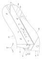
- FIG. 2 is an enlarged perspective view of the fence shown in FIG. 1;
- FIG. 5 is a bottom view of the fence shown in FIG. 4 as seen from below.
- FIG. 5 is an enlarged perspective view of the left side fence portion of the fence shown in FIG. 4 viewed from below.
- FIG. 4 is a cross-sectional view (cross-sectional view taken along the line 7-7 in FIG.
- FIG. 9 is a plan view from above showing the left periphery of the fence of the tabletop circular saw shown in FIG. 8; 10 is a cross-sectional view (cross-sectional view taken along the line 10-10 in FIG. 9) seen from the left side, showing the dust relief mechanism provided in the base shown in FIG. 9.
- FIG. 9 is a plan view from above showing the left periphery of the fence of the tabletop circular saw shown in FIG. 8; 10 is a cross-sectional view (cross-sectional view taken along the line 10-10 in FIG. 9) seen from the left side, showing the dust relief mechanism provided in the base shown in FIG. 9.
- FIGS. 1 to 7. A tabletop circular saw 10 as a working machine according to a first embodiment will be described below with reference to FIGS. 1 to 7.
- arrow UP, arrow FR, and arrow LH shown appropriately in the drawings indicate the upper side, the front side, and the left side of the tabletop circular saw 10, respectively.
- the up-down direction, front-back direction, and left-right direction of the tabletop circular saw 10 are meant.
- the left-right direction corresponds to the first direction of the present invention
- the front-back direction corresponds to the second direction of the present invention.
- the tabletop circular saw 10 is configured as a device that cuts a workpiece W (see FIG. 7).
- the tabletop circular saw 10 includes a base 20 as a base, a fence 30, a circular saw main body 50 as a main body, and a dust release mechanism 70.
- the base 20 constitutes the lower end of the tabletop circular saw 10, and is configured as a stand on which the workpiece W is placed.
- the base 20 includes a base body 22 and a turntable 24.
- the base main body 22 is formed into a substantially flat plate shape with the thickness direction being in the up-down direction. Note that the base body 22 is formed with a predetermined relief portion that is open downward, so that the base body 22 is formed in a concave shape that is open downward.
- a base recess 22A that is open to the upper side is formed approximately at the center in the left-right direction of the base body 22, and the outer side portion of the base recess 22A in the left-right direction in the base body 22 is configured as a side base portion 22B.
- the turntable 24 is placed in the base recess 22A.
- the turntable 24 is formed into a substantially bottomed cylindrical shape that is open downward, and the center portion of the turntable 24 is rotatably supported by the base body 22 with the up-down direction being the axial direction. Further, the upper surface of the turntable 24 and the upper surface of the side base portion 22B are arranged flush with each other. Thereby, by placing the workpiece W on the upper surface of the turntable 24 and rotating the turntable 24, the orientation of the cut surface of the workpiece during cutting can be changed.
- the turntable 24 is integrally formed with a front table part 24A that projects forward and a rear table part 24B that projects rearward.
- the fence 30 extends in the left-right direction and is arranged above the base 20.
- the workpiece W is pressed against the fence 30 from the front to determine the position of the workpiece W with respect to the base 20 and the fence 30 (see FIG. 7).
- the fence 30 includes side fence portions 32L and 32R as fence portions that constitute both left and right portions of the fence 30, and a center fence portion 34 that connects the side fence portions 32L and 32R.
- the side fence parts 32L and 32R are fixed so that they cannot move relative to the base body 22.
- a plurality of (in this embodiment, two locations) fixing bosses 32C are formed on the side fence portion 32R, and the fixing bosses 32C have an axial direction in the up-down direction and a longitudinal direction in the front-back direction. It is formed into a substantially stepped elliptical cylinder shape and extends downward from the bottom wall of the fence groove 32A.
- Fixing bolts (not shown) are inserted into the fixing bosses 32B and 32C from above and are screwed into the side base portion 22B, thereby fixing the side fence portions 32L and 32R to the base body 22.
- the upper surfaces of the inner ends in the left-right direction of the side fence portions 32L and 32R are inclined downward as they move toward the inner side in the left-right direction (the center side in the left-right direction of the fence 30) when viewed from the front. This suppresses interference between the circular saw body 50 and the side fence portions 32L, 32R when the circular saw body 50 is tilted, which will be described later.
- the center fence portion 34 is formed in a substantially semicircular arc shape that is open toward the front when viewed from above.
- the center fence section 34 is disposed on the rear side of the side fence sections 32L, 32R, and both ends of the center fence section 34 in the longitudinal direction are connected to inner ends of the side fence sections 32L, 32R in the left-right direction. Further, the front surface of the center fence section 34 is inclined toward the inner side in the radial direction of the center fence section 34 as it goes downward when viewed from the longitudinal direction.
- the fence 30 is made of metal material. Further, the fence 30 is formed by casting. That is, a relief portion corresponding to the outer shape of the fence 30 is formed inside the fence 30, and the fence 30 is formed in a concave shape that is open downward. A plurality of reinforcing ribs 30A are formed inside the fence 30, and the reinforcing ribs 30A are formed in a substantially lattice shape when viewed from below.
- the left-right inner portions of the side fence portions 32L, 32R and the lower surface of the center fence portion 34, including the reinforcing ribs 30A, are configured as an offset surface 30B (see the hatched portion in FIG. 5).
- the offset surface 30B is arranged to face at least the turntable 24 in the vertical direction, and is offset upwardly with respect to the lower surface of the fence 30.
- the turntable 24 and the offset surface 30B are arranged to face each other in the vertical direction with a predetermined gap therebetween, and the rotation of the turntable 24 is allowed by the gap.
- a sub-fence 36 is provided above the side fence portions 32L and 32R.
- the sub-fence 36 is formed into a substantially box-like shape with a relatively shallow bottom and open to the rear side.
- a rail portion 36A projecting downward is formed on the lower wall of the sub-fence 36, and the rail portion 36A is slidably inserted in the fence groove portions 32A of the side fence portions 32L and 32R in the left-right direction.
- the front surface of the sub-fence 36 is arranged flush with the contact surfaces 32D of the side fence parts 32L and 32R.
- the sub-fence 36 is configured to weaken its fixing force to the base body 22 by operating a fixing knob (not shown) and to be able to move relative to the base body 22 in the left-right direction.
- a vice device 40 for fixing the workpiece W to the base body 22 is provided on the left side base portion 22B of the base body 22 described above.
- the vice device 40 includes a vice shaft 41 extending in the vertical direction on the rear side of the side fence portion 32L, and an arm 42 extending forward from the upper end of the vice shaft 41.
- the vice device 40 also includes a screw shaft 43 that is screwed onto the front end of the arm 42 and extends in the vertical direction, a knob 44 provided at the top end of the screw shaft 43, and a knob 44 provided at the bottom end of the screw shaft 43.
- a vice plate 45 is provided. Then, by placing the workpiece W under the vice plate 45 and rotating the knob 44 to lower the screw shaft 43 and vice plate 45, the workpiece W is moved downward by the vice plate 45. It is configured to be pressed and fixed to the base 20.
- the hinge mechanism 51 has a first hinge 52 and a second hinge 53.
- the first hinge 52 is formed in a substantially elongated box shape that extends in the vertical direction and is open to the rear side.
- the first hinge 52 is disposed on the rear side of the rear table section 24B of the turntable 24, and the lower end of the first hinge 52 is connected to the rear table section by a first connecting shaft 54 whose axial direction is the front-rear direction. 24B.
- the circular saw main body 50 is configured to be tiltable to the right or left with respect to the position shown in FIG.
- a long hole (not shown) extending in the circumferential direction of the first connecting shaft 54 is formed in the first hinge 52 on the radially outer side of the first connecting shaft 54 .
- a fixing bolt is inserted into this elongated hole, and the fixing bolt is screwed into the rear table portion 24B, thereby fixing the first hinge 52 to the turntable 24.
- the configuration is such that the first hinge 52 can be rotated around the first connecting shaft 54 by releasing the fastened state of the fixing bolt.
- the upper part of the first hinge 52 is inclined to the right as it goes upward, and the upper end of the first hinge 52 is disposed at a position shifted to the right with respect to the lower end of the first hinge 52.
- a pair of upper and lower support shafts 55 are provided at the upper end of the first hinge 52 .
- the support shaft 55 is arranged with the front-rear direction as its axial direction, and extends from the first hinge 52 to the front side.
- the second hinge 53 includes a connecting portion 53A slidably connected to the support shaft 55 in the front-rear direction, and a hinge portion 53B extending leftward from the connecting portion 53A.
- the connecting portion 53A is provided with a fixing screw 56 configured to be able to come into contact with the support shaft 55. When the tip of the fixing screw 56 comes into contact with the support shaft 55, the second hinge 53 is moved in the front-rear direction. It is configured to restrict movement.
- the head portion 60 is disposed in front of the hinge portion 53B of the second hinge 53, and the rear end portion of the head portion 60 is rotatable to the hinge portion 53B by a second connecting shaft 61 whose axial direction is in the left-right direction. is supported by Specifically, the hinge portion 53B is formed in a concave shape that is open upward when viewed from the front-rear direction, and the rear end portion of the head portion 60 is inserted into the hinge portion 53B, and the second connecting shaft 61 is inserted into the hinge portion 53B. It spans the hinge portion 53B. Further, the head portion 60 is held by a holding mechanism (not shown).
- the head portion 60 is rotated clockwise around the second connecting shaft 61 and positioned in the forward tilted position shown in FIGS. is inserted from above between the side fence parts 32L and 32R, and the circular saw blade 64 cuts the workpiece on the base 20.
- a motor accommodating portion 60A is formed at the upper end of the head portion 60 and protrudes to the left side, and a motor 62 is accommodated in the motor accommodating portion 60A.
- a handle portion 60B is formed at the front end of the head portion 60, and a trigger 63 is provided on the handle portion 60B so that the trigger 63 can be pulled.
- a switch (not shown) is provided in the handle portion 60B, and is configured to be turned on when the trigger 63 is pulled.
- the switch and motor 62 are electrically connected to a control section (not shown). Thereby, when the trigger 63 is pulled, the motor 62 is driven by the control section.
- a duct portion 66 is integrally formed in the head portion 60 on the rear side of the circular saw blade 64.
- the duct portion 66 is formed into a cylindrical shape extending substantially in the vertical direction.
- the lower end portion of the duct portion 66 is configured as a duct entrance portion 66A, and the duct entrance portion 66A is formed in a substantially U-shape that is open to the front side (toward the circular saw blade 64 side) in a plan view. It is arranged on the rear side with respect to the vertical center of the blade 64.
- the upper end portion of the duct portion 66 is configured as a duct outlet portion 66B, and the duct outlet portion 66B is formed in a substantially cylindrical shape and protrudes upward from the head portion 60 toward the rear side.
- the upper end portion of the duct outlet portion 66B is configured such that a dust bag 67 (see FIG. 2) can be attached thereto.
- dust such as chips scattered from the circular saw blade 64 to the rear side is inserted into the duct part 66 from the duct entrance part 66A, and is discharged into the dust bag 67 from the duct exit part 66B. It looks like this. Thereby, dust is collected in the dust bag 67.
- the dust release mechanism 70 is provided in the side fence portions 32L and 32R of the fence 30, respectively.
- the dust relief mechanism 70 provided on the side fence portion 32L and the dust relief mechanism 70 provided on the side fence portion 32R are symmetrical with respect to the center portion of the tabletop circular saw 10 in the left and right direction, except for the following points. It is composed of Therefore, in the following explanation, the dust escape mechanism 70 provided in the side fence portion 32L will be explained, and the description of the dust escape mechanism 70 provided in the side fence portion 32R will be omitted as appropriate.
- the dust release mechanism 70 releases dust between the workpiece W placed on the base 20 and the side fence portion 32L to the side fence portion 32L side, and removes dust from both sides of the side fence portion 32L in the left and right direction and the side fence. It is configured as a mechanism section that discharges to the rear side of the section 32L.
- the dust escape mechanism 70 is a notch formed at the lower end of the side fence portions 32L, 32R (below the contact surface 32D).
- the dust relief mechanism 70 (notch) is provided at the lower end of the side fence portion 32L, and includes a first relief groove 72 and a plurality of (in this embodiment, three) second relief grooves 74. It consists of
- the dust escape mechanism 70 provided in the side fence portion 32R includes a first relief groove portion 72 and four second relief groove portions 74.
- the first escape groove portion 72 is formed at the lower end portion of the contact surface 32D of the side fence portion 32L.
- the first escape groove portion 72 penetrates along the left-right direction, and is formed in a stepped shape open to the lower side and the front side when viewed from the left-right direction.
- the vertical dimension of the first relief groove 72 is set so that the relatively thin plate-shaped workpiece W does not fit into the first relief groove 72. There is. As an example, the vertical dimension of the first escape groove portion 72 is set to 1.5 mm.
- the second escape groove portion 74 is formed at the lower end portion of the side fence portion 32L.
- the second escape groove portion 74 penetrates along the front-rear direction, and is formed in the shape of a groove that opens downward when viewed from the front. That is, the second escape groove portion 74 is formed in the outer peripheral walls (front wall and rear wall) of the side fence portions 32L and 32R and the lower end portion of the reinforcing rib 30A, and penetrates in the front-rear direction. Thereby, the front end portion of the second relief groove portion 74 communicates with the first relief groove portion 72 .
- an offset surface 30B is formed in the rear wall of the side fence part 32L instead of the second relief groove part 74.
- the width dimension (dimension in the left-right direction) of the second relief groove part 74 is set to be significantly larger than the groove depth (dimension in the vertical direction) of the second relief groove part 74. Further, the groove depth of the second relief groove portion 74 is set larger than the groove depth (vertical dimension) of the first relief groove portion 72, and matches the offset distance from the lower surface of the fence 30 on the offset surface 30B. is set to. That is, the upper surface of the second relief groove part 74 and the offset surface 30B are arranged above the upper surface of the first relief groove part 72.
- a chamfered portion 74A (see FIG. 7) is formed at the front opening edge of the second relief groove portion 74. Furthermore, the plurality of second relief grooves 74 are arranged side by side at predetermined intervals in the left-right direction.
- the workpiece W is placed on the base 20 in front of the fence 30. Then, the workpiece W is moved to the rear side, and the rear surface of the workpiece W is pressed against the contact surfaces 32D of the side fence parts 32L and 32R. Thereby, the position of the workpiece W with respect to the base 20 and the side fence parts 32L, 32R is determined.
- the vise plate 45 presses the workpiece W from above and fixes the workpiece W to the base 20. Then, when the operator grips the handle portion 60B and tilts the head portion 60 forward, the circular saw blade 64 cuts the workpiece.
- dust generated during the cutting process may be prevented from scattering, such as being collected in the dust bag 67 as in the present embodiment. It may remain on the base 20 or the workpiece W. Then, by repeating the cutting process, the remaining dust is deposited on the base 20 (between the workpiece W and the side fence parts 32L and 32R). By moving the workpiece W for positioning each cutting process, the dust on the base 20 is pushed toward the side fence parts 32L and 32R by the workpiece W, and is covered with the side fence parts 32L and 32R. It gets in between the workpiece W and accumulates.
- the accumulated dust makes it impossible to press the workpiece W against the side fence parts 32L and 32R without any gaps, and the position of the workpiece W with respect to the base 20 and the fence 30 changes.
- the angle of the cut surface formed on the workpiece W (angle viewed from the front and back direction, angle viewed from above, etc.) deviates from the set angle.
- the machining accuracy for the workpiece W may be reduced. Therefore, in order to suppress deterioration of processing accuracy, the operator removes dust on the base 20 (dust between the side fence parts 32L, 32R and the workpiece W and between the base 20 and the workpiece W). There is a need. As a result, workability during cutting may deteriorate.
- the dust remaining on the base 20 (between the side fence parts 32L, 32R and the workpiece W) is transferred into the first relief groove 72 and the second relief groove 74. Since the dust is released, it is possible to prevent dust from accumulating on the base 20 (between the side fence portions 32L, 32R and the workpiece W). As a result, it is possible to prevent dust from remaining (intervening) between the base 20 and the workpiece W. Thereby, the position of the workpiece W with respect to the side fence parts 32L, 32R and the base 20 can be determined well, and the workpiece W can be cut.
- the first escape groove portion 72 penetrates in the left-right direction.
- the left end portion of the first relief groove portion 72 is open to the left, and the right end portion is open to the right. Therefore, the dust that has escaped into the first relief groove section 72 can be discharged outward in the left-right direction from both ends of the first relief groove section 72 in the left-right direction.
- the first relief groove portion 72 may be configured such that one end thereof is open in the left-right direction.
- the second escape groove portion 74 penetrates in the front-rear direction. Therefore, the dust escaped into the second relief groove 74 can be discharged from the rear end of the second relief groove 74 to the rear side of the side fence parts 32L, 32R.
- the tabletop circular saw 10 When the tabletop circular saw 10 is in operation, vibrations caused by the drive of the motor 62 are transmitted to the base 20, causing the tabletop circular saw 10 (ie, the base 20) to vibrate. As a result, the vibration causes the dust to move within the first relief groove 72 and be discharged from both ends of the first relief groove 72 in the left and right direction. That is, in the present embodiment, the dust that has moved to the first relief groove 72 or the second relief groove 74 is urged to move further by driving the motor 62, and the dust can be moved to the outside of the base 20. Furthermore, the dust moves within the second relief groove 74 and is discharged from the rear end of the second relief groove 74 .
- the operator can perform cutting on the base 20 (between the side fence portions 32L, 32R and the workpiece W and between the base 20 and the workpiece W) for each cutting process. ) reduces the need to remove dust. Therefore, workability for the worker can be improved.
- the dust release mechanism 70 is provided at the lower end portions of the side fence portions 32L and 32R. That is, the dust release mechanism 70 is arranged on the rear side (on the opposite side to the workpiece W) with respect to the contact surface 32D that the workpiece W comes into contact with. This prevents the dust release mechanism 70 from being disposed in the working area of the base 20 (the area where the workpiece W is placed and is in front of the side fence parts 32L and 32R), and A relief mechanism 70 can be provided in the tabletop circular saw 10. Therefore, the influence on workability caused by providing the dust relief mechanism 70 can be suppressed.
- the upper surface of the second relief groove section 74 is arranged above the upper surface of the first relief groove section 72. That is, the vertical dimension of the second relief groove part 74 is set larger than the vertical dimension of the first relief groove part 72.
- the upper surface of the second relief groove 74 is arranged above the upper surface of the first relief groove 72, but the upper surface of the second relief groove 74 and the upper surface of the first relief groove 72 are The upper and lower positions of the upper surface of the second relief groove part 74 may be set so that they are arranged flush with each other.
- FIGS. 8 to 10 a tabletop circular saw 100 as a working machine according to a second embodiment will be described using FIGS. 8 to 10.
- the tabletop circular saw 100 of the second embodiment is configured in the same manner as the tabletop circular saw 10 of the first embodiment, except for the following points. Note that, in FIGS. 8 to 10, parts configured similarly to those of the tabletop circular saw 10 of the first embodiment are given the same reference numerals.
- the dust escape mechanism 70 is omitted in the fence 30, and the dust escape mechanism 110 (discharge section) is provided in the base body 22 of the base 20.
- the dust escape mechanism 110 (discharge section) is provided on the left and right side base sections 22B of the base body 22, respectively.
- the dust release mechanism 110 provided on the left side base portion 22B and the dust release mechanism 110 provided on the right side base portion 22B are located at the center of the tabletop circular saw 10 in the left-right direction, except for the following points. It is configured symmetrically. Therefore, in the following description, the dust escape mechanism 110 provided on the left side base portion 22B will be explained, and the description of the dust escape mechanism 110 provided on the right side base portion 22B will be omitted as appropriate.
- the dust relief mechanism 110 includes a first relief groove 112 and a plurality of (in this embodiment, five) second relief grooves 114.
- the dust relief mechanism 110 provided on the right side base portion 22B includes a first relief groove portion 112 and seven second relief groove portions 114.
- the first escape groove portion 112 is formed on the upper surface of the side base portion 22B.
- the first escape groove portion 112 is formed in a groove shape that is open upward and extends along the left-right direction, and penetrates in the left-right direction.
- the first relief groove part 112 is located on the front side of the side fence part 32L so that the abutment surface 32D of the side fence part 32L is arranged in the middle part of the first relief groove part 112 in the front-rear direction in plan view. That is, when viewed from the left and right direction, the side fence portion 32L (lower end portion) protrudes forward with respect to the rear surface of the first relief groove portion 112. That is, the contact surface 32D is located forward of the rear surface of the first relief groove portion 112.
- a guide portion 32E is formed at the lower end of the contact surface 32D of the side fence portion 32L, and the guide portion 32E is configured as an inclined surface that slopes toward the front as it goes upward. Further, in the front-rear direction, the lower end position of the guide portion 32E and the rear surface position of the first escape groove portion 112 match, but they may not match. At least a portion of the first relief groove portion 112 (dust relief mechanism 110) is located forward (on the circular saw main body 50 side) of the contact range (attachment location) between the side fence portion 32L and the side base portion 22B.
- the second relief groove 114 is formed on the bottom surface of the first relief groove 112 and penetrates in the vertical direction.
- the second relief groove portion 114 is formed in the shape of a long hole (slit shape) whose longitudinal direction is the left-right direction, and the dimensions of the first relief groove portion 112 and the second relief groove portion 114 in the front-rear direction match. There is.
- the plurality of second relief grooves 114 are arranged side by side at predetermined intervals in the left-right direction. At least a portion of the second escape groove portion 114 is located forward (on the circular saw main body 50 side) of the contact range (attachment location) between the side fence portion 32L and the side base portion 22B.
- the dust remaining on the base 20 (between the side fence parts 32L, 32R and the workpiece W) is removed from the first escape groove part 112. Since the dust is allowed to escape into the second relief groove 114, it is possible to suppress dust from accumulating on the base 20. Therefore, it is possible to suppress the presence of dust between the side fence portions 32L, 32R and the workpiece W, and further between the base 20 and the workpiece W during the cutting process. Also in the second embodiment, dust moves within the first relief groove 112 due to vibrations generated when the motor 62 is driven, and is discharged from both left and right ends of the first relief groove 112 and the second relief groove 114. be done. Therefore, in the second embodiment as well, it is possible to improve workability for the operator, similarly to the first embodiment.
- the first escape groove portion 112 is arranged adjacent to the front side of the side fence portions 32L and 32R in plan view. Thereby, by moving the workpiece W for positioning, the dust moves to the rear side, and the dust that has moved to the rear side can fall into the first escape groove portion 112. At this time, since the dust is blocked by the side fence parts 32L and 32R, the reliability of dropping the dust into the first relief groove part 112 can be improved.
- the contact surfaces 32D (lower end portions) of the side fence portions 32L and 32R are located in front of the rear surface of the first relief groove portion 112 (extended to the front side), and It is arranged above the rear end of the opening in the groove 112.
- a guide portion 32E is formed at the lower end of the contact surface 32D of the side fence portions 32L, 32R, and the guide portion 32E is formed as an inclined surface that slopes toward the front as it goes upward when viewed from the left and right direction. It is configured.
- the dust relief mechanism 70 is configured to include a first relief groove section 72 and a plurality of second relief groove sections 74, but one of the first relief groove section 72 and the second relief groove section 74 is May be omitted. Also in this case, the dust remaining on the base 20 is allowed to escape to the first relief groove 112 or the second relief groove 114, so that the dust is interposed between the workpiece W and the side fence portions 32L, 32R. can be suppressed. Similarly, in the dust relief mechanism 110 of the second embodiment, one of the first relief groove portion 112 and the second relief groove portion 114 may be omitted.
- the dust release mechanism 70 (110) may be provided on the fence 30 and the base 20.
- a third relief groove 76 whose longitudinal direction is in the left-right direction is formed through the side base portion 22B, so that the third relief groove 76 is connected to the second relief groove 74. They may be arranged so as to overlap.
- the dust release mechanism may be provided only on one of the fence 30 and the base 20, or may be provided on both. That is, only one of the cutout portion of the fence 30 and the discharge portion of the base 20 may be mounted, or both may be mounted.
- first relief groove 112 and the second relief groove 114 are located in a range behind the contact surface 32D, but all of the first relief groove 112 and the second relief groove 114 are located in the front of the contact surface 32D. It's okay.
Landscapes
- Engineering & Computer Science (AREA)
- Mechanical Engineering (AREA)
- Life Sciences & Earth Sciences (AREA)
- Wood Science & Technology (AREA)
- Forests & Forestry (AREA)
- Sawing (AREA)
Priority Applications (3)
| Application Number | Priority Date | Filing Date | Title |
|---|---|---|---|
| JP2024505954A JP7842360B2 (ja) | 2022-03-07 | 2023-02-07 | 作業機 |
| US18/842,511 US20250187087A1 (en) | 2022-03-07 | 2023-02-07 | Work machine |
| CN202380024322.7A CN118785988A (zh) | 2022-03-07 | 2023-02-07 | 作业机 |
Applications Claiming Priority (2)
| Application Number | Priority Date | Filing Date | Title |
|---|---|---|---|
| JP2022034814 | 2022-03-07 | ||
| JP2022-034814 | 2022-03-07 |
Publications (1)
| Publication Number | Publication Date |
|---|---|
| WO2023171199A1 true WO2023171199A1 (ja) | 2023-09-14 |
Family
ID=87936615
Family Applications (1)
| Application Number | Title | Priority Date | Filing Date |
|---|---|---|---|
| PCT/JP2023/003916 Ceased WO2023171199A1 (ja) | 2022-03-07 | 2023-02-07 | 作業機 |
Country Status (4)
| Country | Link |
|---|---|
| US (1) | US20250187087A1 (https=) |
| JP (1) | JP7842360B2 (https=) |
| CN (1) | CN118785988A (https=) |
| WO (1) | WO2023171199A1 (https=) |
Citations (2)
| Publication number | Priority date | Publication date | Assignee | Title |
|---|---|---|---|---|
| JP2018154086A (ja) * | 2017-03-21 | 2018-10-04 | 株式会社マキタ | 卓上切断機 |
| JP2021104662A (ja) * | 2019-12-27 | 2021-07-26 | 株式会社マキタ | 卓上切断機 |
Family Cites Families (9)
| Publication number | Priority date | Publication date | Assignee | Title |
|---|---|---|---|---|
| JP2520363Y2 (ja) * | 1989-10-27 | 1996-12-18 | 株式会社日立工機原町 | 卓上切断機の木端侵入防止装置 |
| US5297463A (en) * | 1991-10-09 | 1994-03-29 | Black & Decker Inc. | Adjustable fence for compound miter saw |
| US5735324A (en) * | 1996-03-01 | 1998-04-07 | Ponce; Felix C. | Miter box with electronic measuring of lumber |
| AU1010202A (en) | 2001-01-16 | 2002-07-18 | Techtronic Industries Co., Ltd. | Sliding fence for a compound miter saw |
| JP2007190710A (ja) | 2006-01-17 | 2007-08-02 | Hitachi Koki Co Ltd | 卓上切断機 |
| JP5284055B2 (ja) | 2007-12-12 | 2013-09-11 | 株式会社マキタ | 卓上切断機 |
| US8272304B2 (en) * | 2009-04-28 | 2012-09-25 | Robert Bosch Gmbh | Miter saw with improved dust collection system |
| JP5889740B2 (ja) | 2012-07-11 | 2016-03-22 | 株式会社マキタ | 切断工具 |
| US11478865B2 (en) * | 2020-03-06 | 2022-10-25 | Larry Knittle | Cutting device with integrated and interruptible auxiliary power supply |
-
2023
- 2023-02-07 JP JP2024505954A patent/JP7842360B2/ja active Active
- 2023-02-07 CN CN202380024322.7A patent/CN118785988A/zh active Pending
- 2023-02-07 US US18/842,511 patent/US20250187087A1/en active Pending
- 2023-02-07 WO PCT/JP2023/003916 patent/WO2023171199A1/ja not_active Ceased
Patent Citations (2)
| Publication number | Priority date | Publication date | Assignee | Title |
|---|---|---|---|---|
| JP2018154086A (ja) * | 2017-03-21 | 2018-10-04 | 株式会社マキタ | 卓上切断機 |
| JP2021104662A (ja) * | 2019-12-27 | 2021-07-26 | 株式会社マキタ | 卓上切断機 |
Also Published As
| Publication number | Publication date |
|---|---|
| CN118785988A (zh) | 2024-10-15 |
| US20250187087A1 (en) | 2025-06-12 |
| JP7842360B2 (ja) | 2026-04-08 |
| JPWO2023171199A1 (https=) | 2023-09-14 |
Similar Documents
| Publication | Publication Date | Title |
|---|---|---|
| EP3741486B1 (en) | Blade guard assembly | |
| JP3168328B2 (ja) | 工作機械及び、そのカバー装置 | |
| JP3353083B2 (ja) | コラム固定形工作機械 | |
| EP1707328B1 (en) | Portable cutting tool | |
| US7437816B1 (en) | Lathe with arrangement for dropping chips into a container without blocking moving path of a saddle | |
| JP2005034920A (ja) | 工作機械 | |
| EP1837142A1 (en) | Miter Saw | |
| WO2023171199A1 (ja) | 作業機 | |
| JP4369279B2 (ja) | 丸のこ盤 | |
| JP2002233926A (ja) | 工作機械 | |
| JP7684556B2 (ja) | 作業機 | |
| JP7278853B2 (ja) | チェーンソー | |
| JP2020011402A (ja) | 切断機 | |
| JP3353084B2 (ja) | コラム移動形マシンニングセンタ | |
| JP7278852B2 (ja) | チェーンソー | |
| EP0949048B1 (en) | Mitre saw with angularly adjustable fence | |
| JP2002307232A (ja) | 金工切断機 | |
| JP3611452B2 (ja) | 丸鋸盤の切削粉排出機構 | |
| TW202521279A (zh) | 去除加工機 | |
| JP2024034401A (ja) | 作業機 | |
| JP2859701B2 (ja) | 鋸盤における切粉除去装置 | |
| JP3139928U (ja) | サドルの案内溝を塞ぐことなくコンテナ内に切れ端を落下させる設計を備えた旋盤 | |
| JP2024117350A (ja) | 金工用定置式切断機 | |
| JPH10323804A (ja) | 木材加工機 | |
| JP3969362B2 (ja) | 工作機械 |
Legal Events
| Date | Code | Title | Description |
|---|---|---|---|
| 121 | Ep: the epo has been informed by wipo that ep was designated in this application |
Ref document number: 23766379 Country of ref document: EP Kind code of ref document: A1 |
|
| ENP | Entry into the national phase |
Ref document number: 2024505954 Country of ref document: JP Kind code of ref document: A |
|
| WWE | Wipo information: entry into national phase |
Ref document number: 18842511 Country of ref document: US Ref document number: 202380024322.7 Country of ref document: CN |
|
| NENP | Non-entry into the national phase |
Ref country code: DE |
|
| 122 | Ep: pct application non-entry in european phase |
Ref document number: 23766379 Country of ref document: EP Kind code of ref document: A1 |
|
| WWP | Wipo information: published in national office |
Ref document number: 18842511 Country of ref document: US |