WO2023162330A1 - 光学装置、および光学装置を備える撮像ユニット - Google Patents
光学装置、および光学装置を備える撮像ユニット Download PDFInfo
- Publication number
- WO2023162330A1 WO2023162330A1 PCT/JP2022/039133 JP2022039133W WO2023162330A1 WO 2023162330 A1 WO2023162330 A1 WO 2023162330A1 JP 2022039133 W JP2022039133 W JP 2022039133W WO 2023162330 A1 WO2023162330 A1 WO 2023162330A1
- Authority
- WO
- WIPO (PCT)
- Prior art keywords
- lens
- optical device
- housing
- layer lens
- translucent body
- Prior art date
- Legal status (The legal status is an assumption and is not a legal conclusion. Google has not performed a legal analysis and makes no representation as to the accuracy of the status listed.)
- Ceased
Links
Images






Classifications
-
- G—PHYSICS
- G02—OPTICS
- G02B—OPTICAL ELEMENTS, SYSTEMS OR APPARATUS
- G02B7/00—Mountings, adjusting means, or light-tight connections, for optical elements
- G02B7/02—Mountings, adjusting means, or light-tight connections, for optical elements for lenses
-
- B—PERFORMING OPERATIONS; TRANSPORTING
- B06—GENERATING OR TRANSMITTING MECHANICAL VIBRATIONS IN GENERAL
- B06B—METHODS OR APPARATUS FOR GENERATING OR TRANSMITTING MECHANICAL VIBRATIONS OF INFRASONIC, SONIC, OR ULTRASONIC FREQUENCY, e.g. FOR PERFORMING MECHANICAL WORK IN GENERAL
- B06B1/00—Methods or apparatus for generating mechanical vibrations of infrasonic, sonic, or ultrasonic frequency
- B06B1/02—Methods or apparatus for generating mechanical vibrations of infrasonic, sonic, or ultrasonic frequency making use of electrical energy
- B06B1/06—Methods or apparatus for generating mechanical vibrations of infrasonic, sonic, or ultrasonic frequency making use of electrical energy operating with piezoelectric effect or with electrostriction
-
- B—PERFORMING OPERATIONS; TRANSPORTING
- B60—VEHICLES IN GENERAL
- B60S—SERVICING, CLEANING, REPAIRING, SUPPORTING, LIFTING, OR MANOEUVRING OF VEHICLES, NOT OTHERWISE PROVIDED FOR
- B60S1/00—Cleaning of vehicles
- B60S1/02—Cleaning windscreens, windows or optical devices
- B60S1/56—Cleaning windscreens, windows or optical devices specially adapted for cleaning other parts or devices than front windows or windscreens
-
- G—PHYSICS
- G02—OPTICS
- G02B—OPTICAL ELEMENTS, SYSTEMS OR APPARATUS
- G02B27/00—Optical systems or apparatus not provided for by any of the groups G02B1/00 - G02B26/00, G02B30/00
- G02B27/0006—Optical systems or apparatus not provided for by any of the groups G02B1/00 - G02B26/00, G02B30/00 with means to keep optical surfaces clean, e.g. by preventing or removing dirt, stains, contamination, condensation
-
- G—PHYSICS
- G03—PHOTOGRAPHY; CINEMATOGRAPHY; ANALOGOUS TECHNIQUES USING WAVES OTHER THAN OPTICAL WAVES; ELECTROGRAPHY; HOLOGRAPHY
- G03B—APPARATUS OR ARRANGEMENTS FOR TAKING PHOTOGRAPHS OR FOR PROJECTING OR VIEWING THEM; APPARATUS OR ARRANGEMENTS EMPLOYING ANALOGOUS TECHNIQUES USING WAVES OTHER THAN OPTICAL WAVES; ACCESSORIES THEREFOR
- G03B17/00—Details of cameras or camera bodies; Accessories therefor
- G03B17/02—Bodies
-
- G—PHYSICS
- G03—PHOTOGRAPHY; CINEMATOGRAPHY; ANALOGOUS TECHNIQUES USING WAVES OTHER THAN OPTICAL WAVES; ELECTROGRAPHY; HOLOGRAPHY
- G03B—APPARATUS OR ARRANGEMENTS FOR TAKING PHOTOGRAPHS OR FOR PROJECTING OR VIEWING THEM; APPARATUS OR ARRANGEMENTS EMPLOYING ANALOGOUS TECHNIQUES USING WAVES OTHER THAN OPTICAL WAVES; ACCESSORIES THEREFOR
- G03B17/00—Details of cameras or camera bodies; Accessories therefor
- G03B17/02—Bodies
- G03B17/08—Waterproof bodies or housings
-
- G—PHYSICS
- G03—PHOTOGRAPHY; CINEMATOGRAPHY; ANALOGOUS TECHNIQUES USING WAVES OTHER THAN OPTICAL WAVES; ELECTROGRAPHY; HOLOGRAPHY
- G03B—APPARATUS OR ARRANGEMENTS FOR TAKING PHOTOGRAPHS OR FOR PROJECTING OR VIEWING THEM; APPARATUS OR ARRANGEMENTS EMPLOYING ANALOGOUS TECHNIQUES USING WAVES OTHER THAN OPTICAL WAVES; ACCESSORIES THEREFOR
- G03B5/00—Adjustment of optical system relative to image or object surface other than for focusing
- G03B5/06—Swinging lens about normal to the optical axis
-
- H—ELECTRICITY
- H04—ELECTRIC COMMUNICATION TECHNIQUE
- H04N—PICTORIAL COMMUNICATION, e.g. TELEVISION
- H04N23/00—Cameras or camera modules comprising electronic image sensors; Control thereof
- H04N23/80—Camera processing pipelines; Components thereof
- H04N23/81—Camera processing pipelines; Components thereof for suppressing or minimising disturbance in the image signal generation
-
- H—ELECTRICITY
- H10—SEMICONDUCTOR DEVICES; ELECTRIC SOLID-STATE DEVICES NOT OTHERWISE PROVIDED FOR
- H10N—ELECTRIC SOLID-STATE DEVICES NOT OTHERWISE PROVIDED FOR
- H10N30/00—Piezoelectric or electrostrictive devices
- H10N30/80—Constructional details
- H10N30/802—Circuitry or processes for operating piezoelectric or electrostrictive devices not otherwise provided for, e.g. drive circuits
-
- G—PHYSICS
- G03—PHOTOGRAPHY; CINEMATOGRAPHY; ANALOGOUS TECHNIQUES USING WAVES OTHER THAN OPTICAL WAVES; ELECTROGRAPHY; HOLOGRAPHY
- G03B—APPARATUS OR ARRANGEMENTS FOR TAKING PHOTOGRAPHS OR FOR PROJECTING OR VIEWING THEM; APPARATUS OR ARRANGEMENTS EMPLOYING ANALOGOUS TECHNIQUES USING WAVES OTHER THAN OPTICAL WAVES; ACCESSORIES THEREFOR
- G03B2205/00—Adjustment of optical system relative to image or object surface other than for focusing
- G03B2205/0053—Driving means for the movement of one or more optical element
- G03B2205/0061—Driving means for the movement of one or more optical element using piezoelectric actuators
Definitions
- the present disclosure relates to an optical device and an imaging unit including the optical device.
- Imaging units are installed in the front and rear of the vehicle, and the images obtained by the imaging units are used to control safety devices and perform driving support control. Since such an imaging unit is often provided outside the vehicle, foreign matter such as raindrops (water droplets), mud, dust, etc. may adhere to the translucent body (protective cover or lens) that covers the exterior. If a foreign substance adheres to the translucent body, the foreign substance will be reflected in the image obtained by the imaging unit, making it impossible to obtain a clear image.
- a vibrating body is provided for vibrating the body.
- the image pickup units described in Patent Documents 1 and 2 are composed of an image sensor and an optical device including a translucent body and a lens provided in the direction of the field of view of the image sensor.
- the optical device requires alignment adjustment between the transparent body and the lens so that the light taken in from the transparent body passes through the lens and forms an image on the imaging device.
- there is no configuration for performing alignment adjustment between the translucent body and the lens there is a possibility that the image quality of the image obtained by the imaging device may be degraded.
- an object of the present disclosure is to provide an optical device capable of removing foreign matter adhering to a translucent body covering the outside and improving the image quality of an image obtained by an imaging element, and an imaging unit including the optical device. That is.
- An optical device includes a translucent body, a housing, a vibrating body, a first lens, a fixing section, and a position adjusting section.
- the translucent body transmits light of a predetermined wavelength.
- the housing holds the translucent body.
- the vibrating body vibrates the translucent body held by the housing.
- the first lens is provided in the housing at a position facing the translucent body.
- the fixing section fixes the first lens to the housing.
- the position adjustment section is provided on the fixed section and adjusts the alignment of the first lens with respect to the translucent body.
- the fixed portion is connected to a portion of the housing that becomes a node of vibration by the vibrating body.
- An imaging unit includes the optical device described above and an imaging element arranged such that the translucent body is in the viewing direction.
- the alignment of the first lens with respect to the transparent body is adjusted by the position adjustment section provided in the fixing section. Adhered foreign matter can be removed, and the image quality of the image obtained by the imaging device can be improved.
- FIG. 1 is a cross-sectional view of an optical device according to Embodiment 1;
- FIG. 4A and 4B are schematic diagrams for explaining vibration modes of the optical device according to the first embodiment;
- FIG. 5 is a half cross-sectional view for explaining the position adjusting portion of the optical device according to Embodiment 1;
- FIG. 5 is a schematic diagram for explaining an alignment adjustment method in the position adjustment section of the optical device according to Embodiment 1;
- FIG. 4A and 4B are schematic diagrams for explaining a method of fixing the position adjusting portion of the optical device according to Embodiment 1;
- FIG. 2 is a cross-sectional view of an imaging unit including the optical device according to Embodiment 1;
- FIG. 6 is a half cross-sectional view of an optical device according to Embodiment 2;
- FIG. FIG. 11 is a schematic diagram for explaining an adjustment method in a position adjusting section of the optical device according to Embodiment 2;
- FIG. 11 is a schematic diagram for explaining another adjustment method in the position adjustment section of the optical device according to Embodiment 2;
- FIG. 10 is a diagram for explaining a configuration in which the outermost layer lens and the inner layer lens holding portion are used for fitting in an optical device;
- FIG. 4 is a diagram for explaining a configuration in which an outermost layer lens and an inner layer lens are used for fitting in an optical device;
- FIG. 10 is a diagram for explaining a configuration in which a vibrating body and a holding portion of an inner layer lens are used for fitting in an optical device;
- FIG. 4 is a diagram for explaining a configuration in which a vibrating body and an inner layer lens are used for positioning in an optical device;
- 11 is a half cross-sectional view of an optical device according to Embodiment 3;
- FIG. 11 is a half cross-sectional view of an optical device according to Modification 1 of Embodiment 3;
- FIG. 11 is a half cross-sectional view of an optical device according to Modification 2 of Embodiment 3;
- FIG. 10 is a schematic diagram of an inner lens and a fixing portion according to Modification 2;
- FIG. 11 is a half cross-sectional view of an optical device according to Embodiment 4;
- optical device according to an embodiment and an imaging unit including the optical device will be described in detail below with reference to the drawings.
- the same reference numerals in the drawings indicate the same or corresponding parts.
- the optical device described below is applied to, for example, a vehicle-mounted imaging unit, and can vibrate the translucent body (for example, the outermost layer lens) to remove foreign matter adhering to the surface of the translucent body.
- the optical device is not limited to use as an in-vehicle imaging unit.
- the optical device can be applied to surveillance cameras for security, imaging units for drones, and the like.
- FIG. 1 is a cross-sectional view of an optical device 100 according to Embodiment 1.
- the optical device 100 has an outermost layer lens 1 , a housing 2 , a vibrating body 3 , an inner layer lens 4 , a fixing section 5 and a position adjusting section 6 .
- the outermost layer lens 1 is a translucent body that transmits light of a predetermined wavelength (for example, the wavelength of visible light, the wavelength that can be imaged by an imaging device, etc.), and is, for example, a convex meniscus lens.
- a predetermined wavelength for example, the wavelength of visible light, the wavelength that can be imaged by an imaging device, etc.
- the optical device 100 may use a transparent member such as a protective cover instead of the outermost lens 1 .
- the protective cover is made of resin such as glass or transparent plastics.
- the edge of the outermost layer lens 1 is held by the edge of the housing 2 .
- the optical device 100 is provided with a vibrating body 3 at a position in contact with the outermost layer lens 1 .
- the vibrating body 3 has a cylindrical shape, and the inner layer lens 4 is arranged in the cylinder.
- the vibrating body 3 has a connecting portion 31 that connects with the outermost layer lens 1 (translucent body), and a vibrating portion 32 in which the piezoelectric element 7 is provided.
- the connecting portion 31 is a portion that converts the vibration of the piezoelectric element 7 and has a crank shape.
- the vibrating portion 32 is a portion that vibrates together with the vibration of the piezoelectric element 7 and is thicker than the thin connecting portion 31 .
- the connecting portion 31 and the vibrating portion 32 may be formed integrally or separately.
- the piezoelectric element 7 is provided on the surface of the vibrating body 3 opposite to the side in contact with the outermost lens 1 .
- the piezoelectric element 7 has a hollow circular shape, and vibrates by being polarized in the thickness direction, for example.
- the piezoelectric element 7 is made of lead zirconate titanate piezoelectric ceramics. However, other piezoelectric ceramics such as (K, Na)NbO 3 may be used. Furthermore, a piezoelectric single crystal such as LiTaO 3 may be used.
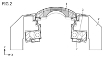
- FIG. 2 is a schematic diagram for explaining vibration modes of the optical device 100 according to the first embodiment.
- the portion (connecting portion 31) holding the outermost layer lens 1 is elastically deformed like a leaf spring to transmit the vibration of the vibrating body 3 to the outermost layer lens 1.
- a portion away from the outermost layer lens 1 is a vibration node.
- the vibration node is a portion having an amplitude of approximately 1/50 or less of the maximum amplitude of the vibrating body 3 . Therefore, the displacement of the central portion of the outermost layer lens 1 becomes maximum due to the vibration of the vibrating body 3, while the displacement of the portion distant from the outermost layer lens 1 becomes small.
- the shades of hatching indicate the magnitude of displacement, and the darker hatching indicates the portion with greater displacement, with the displacement being greater at the central portion of the outermost layer lens 1 .
- the optical device 100 has a fixing portion 5 at a portion of the housing 2 that becomes a node of vibration, specifically near the lower end side opposite to the upper end side holding the outermost layer lens 1 in the housing 2 .
- the vibration of the vibrating body 3 is not propagated to the inner lens 4.
- image quality does not deteriorate due to vibration of the vibrating body 3 .
- the inner lens 4 does not attenuate the vibration of the vibrating body 3, and the ability to remove foreign matter adhering to the outermost lens 1. does not decrease.
- the fixing portion 5 that fixes the inner lens 4 to the housing 2 preferably has a smaller mechanical quality factor Qm than the housing 2 .
- the fixing portion 5 is preferably made of resin.
- the inner lens 4 has a structure in which a plurality of lenses are held by an inner lens barrel 4a.
- the inner lens barrel 4 a is a holding portion for the inner lens 4 . Since a plurality of lenses constituting the inner lens 4 are held by the inner lens barrel 4a in an aligned state, there is no need to adjust the alignment of each individual lens again when mounting it on the optical device 100. - ⁇ However, if alignment adjustment is not performed when the outermost layer lens 1 and the inner layer lens 4 are mounted in the optical device 100, the image quality of the image obtained by the imaging element may deteriorate.
- the outermost lens 1 is not a lens but a light-transmitting body such as a protective cover
- the optical characteristics of the light-transmitting body such as refracting of light transmitted through the light-transmitting body, may affect the image obtained by the imaging device. Alignment adjustment between the translucent body and the inner layer lens 4 is necessary because of the effect.
- FIG. 3 is a half cross-sectional view for explaining the position adjusting section 6 of the optical device 100 according to the first embodiment.
- a dashed-dotted line shown in FIG. 3 is a portion passing through the central axis of the optical device 100 .
- the position adjusting portion 6 shown in FIG. 3 has a thread groove 6a provided in the inner wall surface of the housing 2 and two ring-shaped screws 6b and 6c corresponding to the thread groove 6a.
- the position adjusting portion 6 can fix the position of the inner layer lens 4 with respect to the housing 2 by sandwiching the end portion of the fixing portion 5 with two ring-shaped screws 6b and 6c.
- the position adjusting portion 6 moves the two ring-shaped screws 6b and 6c along the thread groove 6a, and moves the fixing portion 5 in the Z direction. can move.
- the position adjusting unit 6 can move the inner lens 4 in the direction of arrow B (Z direction) with respect to the outermost lens 1 to adjust the focal position. Since the position adjusting portion 6 is provided in a portion of the housing 2 where the vibration of the vibrating body 3 is suppressed, it is possible to suppress positional deviation due to damage or vibration of the position adjusting portion.
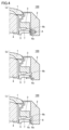
- FIG. 4 is a schematic diagram for explaining an alignment adjustment method in the position adjustment section 6 of the optical device 100 according to the first embodiment.
- the position of the inner layer lens 4 in the Z direction is determined by fitting the ring-shaped screw 6b into the screw groove 6a and rotating it.
- the end portion of the fixing portion 5 fixed to the inner layer lens 4 is brought into contact with the positioned ring-shaped screw 6b to determine the angle ⁇ (elevation angle) formed by the optical axis of the inner layer lens 4 with respect to the optical axis of the outermost layer lens 1. can be adjusted with
- the outermost layer lens 1 is The optical axis adjustment is completed by matching the optical axis of the inner layer lens 4 with the optical axis.
- the ring-shaped screw 6c is fitted into the thread groove 6a and rotated, and the end of the fixed portion 5 is sandwiched between the two ring-shaped screws 6b and 6c.
- the position of the inner layer lens 4 is fixed with respect to .
- the position of the inner layer lens 4 is fixed to the housing 2 by sandwiching the end of the fixed part 5 with two ring-shaped screws 6b and 6c. It is not limited to this method.
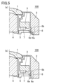
- FIG. 5 is a schematic diagram for explaining a method of fixing the position adjustment section 6 of the optical device 100 according to Embodiment 1.
- FIG. 5(a) instead of the ring-shaped screw 6c, a metal or resin plate 6d that can be crimped is fitted into the thread groove 6a, and the crimped plate 6d and the ring-shaped screw 6b are connected to the end of the fixed portion 5. is sandwiched and fixed. The state of the plate 6d after caulking is indicated by broken lines.
- a block 6e fitted in the thread groove 6a and a ring-shaped screw 6b sandwich the end of the fixing portion 5 and fix them with an adhesive or the like.
- the end portion of the fixing portion 5 may be fixed to the ring-shaped screw 6b only with an adhesive without providing the block 6e.
- the ring-shaped screw 6b is used to adjust the position of the inner layer lens 4 in the Z direction, but a threaded portion may be directly provided at the end of the fixing portion 5.
- the position adjusting portion 6 has a threaded portion at the end of the fixed portion 5, and changes the position with respect to the housing 2 provided with a thread groove 6a (groove portion) corresponding to the threaded portion to adjust the outermost layer lens 1. Adjust the alignment of the inner layer lens 4 with respect to. Thereby, the position adjusting section 6 can adjust the position of the inner layer lens 4 in the Z direction without providing the ring-shaped screw 6b.
- FIG. 6 is a cross-sectional view of an imaging unit 200 including the optical device 100 according to Embodiment 1.
- the imaging unit 200 has an optical device 100 and an imaging device 8 arranged so that the outermost layer lens 1 and the inner layer lens 4 are in the viewing direction.
- the imaging element 8 is an image sensor such as a CCD (Charge Coupled Device) or CMOS (Complementary Metal-Oxide-Semiconductor) sensor, and is mounted on the circuit board 9 . After performing alignment adjustment between the imaging device 8 mounted on the circuit board 9 and the inner layer lens 4, the circuit board 9 is fixed to the fixing portion 5 with an adhesive. Finally, the imaging unit 200 is completed by joining the case 10 and the housing 2 and fixing them with screws or an adhesive.
- CCD Charge Coupled Device
- CMOS Complementary Metal-Oxide-Semiconductor
- the optical device 100 includes the outermost layer lens 1 (light-transmitting body), the housing 2, the vibrating body 3, the inner layer lens 4 (first lens), the fixing section 5, and the position adjusting section. 6.
- the outermost layer lens 1 transmits light of a predetermined wavelength.
- the housing 2 holds the outermost layer lens 1 .
- the vibrating body 3 vibrates the outermost layer lens 1 held in the housing 2 .
- the inner lens 4 is provided at a position facing the outermost lens 1 within the housing 2 .
- the fixing portion 5 fixes the inner lens 4 to the housing 2 .
- the position adjustment section 6 is provided on the fixed section 5 and adjusts the alignment of the inner layer lens 4 with respect to the outermost layer lens 1 .
- the fixing portion 5 is connected to a portion of the housing 2 that becomes a node of vibration by the vibrating body 3 .
- the position adjusting portion provided in the fixing portion 5 connected to the portion of the housing 2 that is a node of the vibration of the vibrating body 3 is adjusted to the outermost layer lens 1 . Since the alignment of the inner layer lens 4 is adjusted, foreign matter adhering to the outermost layer lens 1 covering the outside can be removed, and the image quality of the image obtained by the imaging device 8 can be improved.
- the translucent body is preferably the outermost layer lens 1 (second lens). Of course, a protective cover that is not a lens may be used. It is preferable that the piezoelectric element 7 is provided on at least one surface of the vibrating body 3 . In FIG. 1, the hollow circular piezoelectric element 7 is provided on the bottom surface of the vibrating body 3. Alternatively, a piezoelectric element may be provided on another surface. A plurality of shaped piezoelectric elements 7 may be provided concentrically.
- the fixed part 5 preferably has a smaller mechanical quality factor Qm than the housing 2 . Moreover, it is preferable that the fixed part 5 is made of resin. This makes it difficult for the inner lens 4 to propagate the vibration of the vibrating body 3 through the fixed portion 5 .
- the position adjusting part 6 is preferably provided at the end of the fixing part 5 connected to the housing 2 .
- two ring-shaped screws 6 b and 6 c sandwiching the end of the fixing portion 5 constitute the position adjusting portion 6 . Since the fixed part 5 is connected to the part of the housing 2 that becomes a node of the vibration of the vibrating body 3, by providing the position adjusting part 6 at the end of the fixed part 5, the influence of the vibration caused by the vibrating body 3 can be reduced. Alignment can be adjusted with high accuracy without being affected, and the image quality of the image obtained by the imaging device 8 is improved.
- the imaging unit 200 includes an optical device 100 and an imaging element 8 arranged so that the outermost layer lens 1 and the inner layer lens 4 are in the viewing direction. As a result, the imaging unit 200 can perform highly accurate alignment adjustment in the optical device 100, and the image quality of the image obtained by the imaging device 8 is improved.
- FIG. 7 is a half cross-sectional view of an optical device 100a according to Embodiment 2.
- FIG. 7 the same components as those of optical device 100 according to Embodiment 1 are denoted by the same reference numerals, and description thereof will not be repeated.
- the position adjusting portion 6 is a screw portion 6f provided at the end portion of the fixing portion 5 connected to the inner layer lens 4. As shown in FIG. A groove corresponding to the threaded portion 6f is provided in the inner lens barrel 4a.
- the position adjustment unit 6 moves the inner lens barrel 4a along the threaded portion 6f, thereby moving the inner lens 4 in the Z direction. Therefore, the position adjusting unit 6 can move the inner lens 4 in the direction of arrow B (Z direction) with respect to the outermost lens 1 to adjust the focal position.
- FIG. 8 is a schematic diagram for explaining an alignment adjustment method in the position adjustment section 6 of the optical device 100a according to the second embodiment.
- the flat portion of the inner layer lens barrel 4a and the flat portion of the outermost layer lens 1 are brought into contact with each other, thereby fixing the outermost layer lens.
- the angle ⁇ (elevation angle) formed by the optical axis of the inner layer lens 4 with respect to the optical axis of 1 can be adjusted by guessing. Further, by moving the inner lens 4 and the fixed part 5 in the X and Y directions with the flat part of the inner lens barrel 4 a in contact with the flat part of the outermost lens 1 , the inner lens 4 is aligned with the optical axis of the outermost lens 1 . are aligned to complete the optical axis adjustment.
- the end of the fixed part 5 is fixed to the housing 2 with an adhesive at the position of the inner layer lens 4 where the alignment adjustment with respect to the outermost layer lens 1 has been performed.
- the position of the inner layer lens 4 is fixed to the housing 2 by fixing the end of the fixing portion 5 to the housing 2 with an adhesive. The method is not limited.
- the position of the inner lens 4 in the Z direction is determined by rotating the inner lens barrel 4a in the direction of arrow A with respect to the threaded portion 6f.
- the imaging unit 200 is formed by attaching the case 10 including the imaging device 8 shown in FIG. 6 to the optical device 100a.
- FIG. 9 is a schematic diagram for explaining another adjustment method in the position adjusting section 6 of the optical device 100a according to the second embodiment.
- the housing 2 is provided with a projecting portion 6h for joining with the fixing portion 5.
- the angle ⁇ (elevation angle) formed by the optical axis of the inner lens 4 with respect to the optical axis of the outermost lens 1 is adjusted by guessing. That is, in a state in which the fixed portion 5 is not fixed to the housing 2, the angle ⁇ formed by the optical axis of the inner layer lens 4 with respect to the optical axis of the outermost layer lens 1 can be adjusted by bringing the end portion of the fixed portion 5 and the protrusion 6h into contact with each other. (elevation angle) can be adjusted by guessing.
- the inner lens barrel 4a is rotated in the direction of arrow A with respect to the threaded portion 6f so that the tapered portion of the inner lens barrel 4a contacts the tapered portion of the vibrating body 3.
- the barrel 4a is brought closer to the vibrating body 3.
- the inner lens 4 and the fixed portion 5 are moved in the X and Y directions, and the optical axis of the inner lens 4 is aligned with the optical axis of the outermost lens 1. are matched to complete the optical axis adjustment.
- the end portion of the fixing portion 5 is moved to the projection portion by the block 6i. 6h to fix the position of the inner lens 4.
- the method for fixing the position of the inner layer lens 4 is not limited to the block 6i, and may be fixed only with a plate that can be crimped or with an adhesive.
- the position of the inner lens 4 in the Z direction is determined by rotating the inner lens barrel 4a in the direction of arrow A with respect to the threaded portion 6f.
- the position adjusting section 6 can move the inner layer lens 4 in the Z direction with respect to the outermost layer lens 1 to adjust the focal position.
- the alignment is adjusted by contacting the flat portion of the inner lens barrel 4a with the flat portion of the outermost lens 1, or by contacting the tapered portion of the inner lens barrel 4a with the tapered portion of the vibrating body 3. It is carried out.
- the configuration that can be used for guessing will be collectively described.
- FIG. 10 is a diagram for explaining a configuration in which the outermost layer lens 1 and the holding portion (inner layer lens barrel 4a) of the inner layer lens 4 are used for fitting in the optical device.
- FIG. 10A shows alignment adjustment (mainly the angle ⁇ (elevation angle)) of the inner lens 4 with respect to the outermost lens 1 by bringing the flat surface of the outermost lens 1 and the flat surface 4b of the inner lens barrel 4a into contact. It shows that it can be done by guessing.
- FIG. 10B shows alignment adjustment (mainly in the X and Y directions) of the inner lens 4 with respect to the outermost lens 1 by bringing the tapered portion of the outermost lens 1 and the tapered portion 4c of the inner lens barrel 4a into contact. It shows what you can do with determination.
- FIG. 10(c) shows alignment adjustment (mainly in the X and Y directions) of the inner lens 4 with respect to the outermost lens 1 by bringing the concave portion 1a of the outermost lens 1 and the convex portion 4d of the inner lens barrel 4a into contact. It shows what you can do with determination.
- the shapes formed in the outermost layer lens 1 and the inner layer lens barrel 4a are not limited to the concave portion 1a and the convex portion 4d, and may be reversed.
- FIG. 11 is a diagram for explaining a configuration in which the outermost layer lens 1 and the inner layer lens 4 are used for fitting in an optical device.
- FIG. 11A shows alignment adjustment (mainly the angle ⁇ (elevation angle)) of the inner layer lens 4 with respect to the outermost layer lens 1 by bringing the plane portion of the outermost layer lens 1 and the plane portion 4e of the inner layer lens 4 into contact. It shows what you can do with determination.
- the tapered portion of the outermost layer lens 1 and the tapered portion of the inner layer lens 4 are brought into contact with each other so that the alignment adjustment (mainly in the X and Y directions) of the inner layer lens 4 with respect to the outermost layer lens 1 can be determined. It shows what you can do.
- the concave portion 1a of the outermost layer lens 1 and the convex portion 4f of the inner layer lens 4 are brought into contact with each other to adjust the alignment of the inner layer lens 4 with respect to the outermost layer lens 1 (mainly in the X and Y directions). It shows what you can do with
- the shapes formed in the outermost layer lens 1 and the inner layer lens 4 are not limited to the concave portion 1a and the convex portion 4f, and may be reversed.
- FIG. 12 is a diagram for explaining a configuration in which the vibrating body 3 and the holding portion (inner layer lens barrel 4a) of the inner layer lens 4 are used for fitting in the optical device.
- FIG. 12A shows alignment adjustment (mainly the angle ⁇ (elevation angle)) of the inner lens 4 with respect to the outermost lens 1 by bringing the flat surface of the vibrating body 3 and the flat surface 4b of the inner lens barrel 4a into contact. It shows what you can do with determination.
- the alignment adjustment (mainly in the X and Y directions) of the inner lens 4 with respect to the outermost lens 1 is determined by bringing the tapered portion of the vibrating body 3 and the tapered portion 4c of the inner lens barrel 4a into contact. It shows what you can do with
- the concave portion 3a of the vibrating body 3 and the convex portion 4d of the inner lens barrel 4a are brought into contact with each other to adjust the alignment of the inner lens 4 with respect to the outermost lens 1 (mainly in the X and Y directions). It shows what you can do with
- the shapes formed on the vibrating body 3 and the inner lens barrel 4a are not limited to the concave portion 3a and the convex portion 4d, and may be reversed.
- FIG. 13 is a diagram for explaining a configuration in which the vibrating body 3 and the inner layer lens 4 are used for fitting in an optical device.
- FIG. 13A shows alignment adjustment (mainly the angle ⁇ (elevation angle)) of the inner layer lens 4 with respect to the outermost layer lens 1 by bringing the plane portion of the vibrating body 3 and the plane portion 4e of the inner layer lens 4 into contact. It shows what you can do with
- alignment adjustment (mainly in the X and Y directions) of the inner layer lens 4 with respect to the outermost layer lens 1 is performed by contacting the tapered portion of the vibrating body 3 and the tapered portion of the inner layer lens 4. shows that it is possible.
- alignment adjustment (mainly in the X and Y directions) of the inner layer lens 4 with respect to the outermost layer lens 1 can be determined by bringing the concave portion 3a of the vibrating body 3 and the convex portion 4f of the inner layer lens 4 into contact. It shows what you can do.
- the shapes formed in the vibrating body 3 and the inner layer lens 4 are not limited to the concave portion 3a and the convex portion 4f, and may be reversed.
- the configuration for determination described with reference to FIGS. 10 to 12 can be used not only for the optical device 100a according to Embodiment 2, but also for optical devices according to other embodiments.
- the position adjusting section 6 is provided at the end of the fixed section 5 connected to the inner lens 4. As shown in FIG. Further, the position adjusting portion 6 has a screw portion 6f at the end portion of the fixing portion 5, and changes the position with respect to the inner layer lens barrel 4a provided with a groove portion corresponding to the screw portion 6f. Adjust the alignment of the outermost layer lens 1 with respect to .
- the position adjusting portion provided in the fixing portion 5 connected to the portion of the housing 2 that is a node of vibration by the vibrating body 3 allows the outermost layer lens 1 to Since the alignment of the inner layer lens 4 is adjusted, it is possible to remove foreign matter adhering to the outermost layer lens 1 covering the outside and to improve the image quality of the image obtained by the imaging device.
- the threaded portion 6f at the end of the fixing portion 5 provided in the second embodiment may be provided in the optical device according to another embodiment.
- the outermost layer lens 1 or vibrating body 3 has a plane portion (first plane portion), the inner layer lens 4 or inner lens barrel 4a has plane portions 4e and 4b (second plane portion), and a plane portion ( It is preferable that the flat portions 4e and 4b (second flat portions) can contact with each other.
- the outermost lens 1 or vibrating body 3 has a tapered portion (first tapered portion), the inner lens 4 or inner lens barrel 4a has a tapered portion 4c (second tapered portion), and a tapered portion (first tapered portion). (taper portion) and the taper portion 4c (second taper portion) are preferably contactable.
- the outermost lens 1 or vibrating body 3 has concave portions 1a and 3a (first fitting portion), and the inner lens 4 or inner lens barrel 4a has convex portions 4f and 4d (second fitting portion).
- the concave portions 1a, 3a (first fitting portions) and the convex portions 4f, 4d (second fitting portions) are preferably fittable. As a result, the alignment adjustment of the inner layer lens 4 with respect to the outermost layer lens 1 can be performed by guessing.
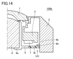
- FIG. 14 is a half cross-sectional view of an optical device 100b according to Embodiment 3.
- FIG. 14 the same components as those of optical device 100 according to Embodiment 1 are denoted by the same reference numerals, and description thereof will not be repeated.
- the housing 2 is provided with a projecting portion 6h for joining with the fixing portion 5.
- the projection 6h and the end of the fixing portion 5 are bonded together with an ultraviolet curable adhesive 6k. Afterwards, it is necessary to irradiate with ultraviolet (UV) light.
- UV ultraviolet
- the projecting portion 6h and the fixing portion 5 have a structure that does not transmit ultraviolet rays, even if the projecting portion 6h and the end portion of the fixing portion 5 are adhered to each other and then irradiated with ultraviolet rays, the projection portion 6h and the fixing portion 5 will not be separated. There is a risk that the adhesive 6k between the ends will not harden.
- the end portion of the fixed portion 5 has a member 6j that transmits ultraviolet rays.
- the member 6j transmits ultraviolet rays, so that the UV-curable adhesive 6k provided between the member 6j and the projection 6h located opposite to the member 6j is aligned with the outermost lens 1. It can be cured after conditioning.
- the fixing portion 5 not only the end portion of the fixing portion 5 but also the fixing portion 5 itself may be the member 6j that transmits ultraviolet rays.
- FIG. 15 is a half cross-sectional view of an optical device 100c according to Modification 1 of Embodiment 3.
- FIG. 15 the same components as those of the optical device 100 according to Embodiment 1 are denoted by the same reference numerals, and the description thereof will not be repeated.
- the optical device 100c has at least one window 6m that transmits ultraviolet light at the end of the fixed portion 5.
- the window portion 6m transmits ultraviolet rays, so that the ultraviolet curing adhesive 6k provided between the window portion 6m and the projection portion 6h located opposite to the window portion 6m is applied to the inner layer lens 4 with respect to the outermost layer lens 1. It can be cured after adjusting the alignment.
- FIG. 16 is a half cross-sectional view of an optical device 100d according to Modification 2 of Embodiment 3.
- FIG. FIG. 17 is a schematic diagram of the inner layer lens 4 and the fixing portion 5 according to Modification 2. As shown in FIG. In optical device 100d shown in FIGS. 16 and 17, the same components as optical device 100 according to Embodiment 1 are denoted by the same reference numerals, and description thereof will not be repeated.
- the optical device 100d has at least one slit 6n at the end of the fixed portion 5.
- a plurality of slits 6n are provided so as to surround the outer periphery of the fixed portion 5 as shown in FIG.
- the slits 6n transmit ultraviolet rays, so that the ultraviolet curing adhesive 6k provided between the slits 6n and the projections 6h located opposite to the slits 6n is used to align the inner lens 4 with respect to the outermost lens 1. It can be cured after conditioning.
- the fixed portion 5 has the member 6j or at least one window portion 6m that transmits ultraviolet rays at the end portion, and the member 6j or the window portion 6m By transmitting ultraviolet rays, the ultraviolet curing adhesive 6k provided between the member 6j or the projection 6h located opposite the window 6m is aligned with the outermost lens 1. can be cured after adjustment. As a result, the optical devices 100b and 100c can be fixed to the housing 2 at the position of the end of the fixed portion 5 after the alignment adjustment.
- the fixed portion 5 has at least one slit 6n at the end, and the slit 6n transmits ultraviolet rays, thereby forming a protrusion at a position facing the slit 6n.
- the ultraviolet curable adhesive 6k provided between the portion 6h and the portion 6h can be cured after the alignment of the inner layer lens 4 with respect to the outermost layer lens 1 is adjusted.
- the optical device 100d can be fixed to the housing 2 at the position of the end portion of the fixed portion 5 after the alignment adjustment.
- Embodiment 4 In Embodiment 1, it was explained that the end portion of the fixing portion 5 is fixed after the alignment adjustment. In the fourth embodiment, a configuration for actively performing alignment adjustment in response to alignment fluctuations is employed as the position adjustment section. 18 is a half cross-sectional view of an optical device according to Embodiment 4. FIG. In optical device 100e shown in FIG. 18, the same components as those of optical device 100 according to Embodiment 1 are denoted by the same reference numerals, and description thereof will not be repeated.
- an actuator 6 P is provided at the end of the fixed part 5 connected to the housing 2 as a position adjusting part for performing alignment adjustment between the outermost lens 1 and the inner lens 4 .
- the actuator 6P is composed of a piezoelectric body (single layer, laminated layer), a motor (voice coil motor), and the like.
- the actuator 6P moves the outermost layer lens 1 based on a control signal from a control circuit (not shown) that detects a change in alignment from an image acquired by the imaging element 8 and the output of a sensor provided on the inner layer lens 4 or the like.
- the actuator 6P may be provided at the end of the fixed portion 5 connected to the inner layer lens 4 .
- the actuator 6P provided at the end of the fixed portion 5 serves as the position adjusting portion. Accordingly, in the optical device 100e, it is possible to actively perform alignment adjustment in response to variations in the alignment of the inner lens 4 with respect to the outermost lens 1, thereby improving the image quality of the image obtained by the imaging device.
- the imaging unit 200 may include a camera, LiDAR, Radar, and the like. Alternatively, a plurality of imaging units may be arranged side by side.
- the imaging unit 200 is not limited to an imaging unit provided in a vehicle, and includes an optical device and an imaging element arranged so that the translucent body is in the viewing direction. The same can be applied to any image pickup unit that needs to remove foreign matter from.
Landscapes
- Physics & Mathematics (AREA)
- General Physics & Mathematics (AREA)
- Engineering & Computer Science (AREA)
- Mechanical Engineering (AREA)
- Optics & Photonics (AREA)
- Multimedia (AREA)
- Signal Processing (AREA)
- Lens Barrels (AREA)
- Studio Devices (AREA)
- Camera Bodies And Camera Details Or Accessories (AREA)
Priority Applications (4)
| Application Number | Priority Date | Filing Date | Title |
|---|---|---|---|
| CN202280092044.4A CN118742839A (zh) | 2022-02-25 | 2022-10-20 | 光学装置和包括光学装置的摄像单元 |
| JP2024502811A JPWO2023162330A1 (https=) | 2022-02-25 | 2022-10-20 | |
| DE112022006181.2T DE112022006181T5 (de) | 2022-02-25 | 2022-10-20 | Optische vorrichtung und bilderzeugungseinheit, die die optische vorrichtung umfasst |
| US18/762,179 US20240353677A1 (en) | 2022-02-25 | 2024-07-02 | Optical device and imaging unit including optical device |
Applications Claiming Priority (2)
| Application Number | Priority Date | Filing Date | Title |
|---|---|---|---|
| JP2022028248 | 2022-02-25 | ||
| JP2022-028248 | 2022-02-25 |
Related Child Applications (1)
| Application Number | Title | Priority Date | Filing Date |
|---|---|---|---|
| US18/762,179 Continuation US20240353677A1 (en) | 2022-02-25 | 2024-07-02 | Optical device and imaging unit including optical device |
Publications (1)
| Publication Number | Publication Date |
|---|---|
| WO2023162330A1 true WO2023162330A1 (ja) | 2023-08-31 |
Family
ID=87765376
Family Applications (1)
| Application Number | Title | Priority Date | Filing Date |
|---|---|---|---|
| PCT/JP2022/039133 Ceased WO2023162330A1 (ja) | 2022-02-25 | 2022-10-20 | 光学装置、および光学装置を備える撮像ユニット |
Country Status (5)
| Country | Link |
|---|---|
| US (1) | US20240353677A1 (https=) |
| JP (1) | JPWO2023162330A1 (https=) |
| CN (1) | CN118742839A (https=) |
| DE (1) | DE112022006181T5 (https=) |
| WO (1) | WO2023162330A1 (https=) |
Citations (4)
| Publication number | Priority date | Publication date | Assignee | Title |
|---|---|---|---|---|
| JP2012018204A (ja) * | 2010-07-06 | 2012-01-26 | Panasonic Corp | 撮像装置及び携帯電子機器 |
| JP2017085276A (ja) * | 2015-10-26 | 2017-05-18 | オリンパス株式会社 | 液滴排除装置と、液滴排除装置を有する画像装置、及び液滴排除装置の制御方法、液滴排除装置の制御プログラム |
| JP2019536018A (ja) * | 2016-11-01 | 2019-12-12 | 日本テキサス・インスツルメンツ合同会社 | 欠陥又は劣化を検出するためのインピーダンス監視を備える超音波レンズクリーニングシステム |
| WO2021186898A1 (ja) * | 2020-03-19 | 2021-09-23 | 株式会社村田製作所 | 振動装置及び振動制御方法 |
Family Cites Families (10)
| Publication number | Priority date | Publication date | Assignee | Title |
|---|---|---|---|---|
| JP2988762B2 (ja) * | 1991-09-30 | 1999-12-13 | 株式会社ミツトヨ | 走査型顕微鏡の光軸調整装置 |
| JPH10193669A (ja) * | 1996-12-27 | 1998-07-28 | Canon Inc | 計測装置及びその制御方法 |
| JP3526805B2 (ja) * | 2000-03-28 | 2004-05-17 | 株式会社立山アールアンドディ | 対物鏡と広角画像入力装置 |
| JP2012078751A (ja) * | 2010-10-06 | 2012-04-19 | Seiko Epson Corp | プロジェクター |
| JP2012114728A (ja) * | 2010-11-25 | 2012-06-14 | Olympus Imaging Corp | 撮像装置 |
| JP5747064B2 (ja) * | 2013-10-11 | 2015-07-08 | 株式会社キーエンス | 光学情報読取装置及び光学情報読取装置用の設定装置 |
| US10401618B2 (en) | 2015-03-11 | 2019-09-03 | Texas Instruments Incorporated | Ultrasonic lens cleaning system with current sensing |
| JP2017170303A (ja) | 2016-03-22 | 2017-09-28 | オリンパス株式会社 | 液滴排除装置と、液滴排除装置を有する画像装置及び上記液滴排除装置の制御方法と上記液滴排除装置の制御プログラム |
| WO2018100795A1 (ja) * | 2016-11-30 | 2018-06-07 | 株式会社村田製作所 | 振動装置、カメラ用水滴除去装置及びカメラ |
| JP2020086251A (ja) * | 2018-11-28 | 2020-06-04 | 京セラ株式会社 | レンズユニット、レンズユニットの製造方法 |
-
2022
- 2022-10-20 JP JP2024502811A patent/JPWO2023162330A1/ja active Pending
- 2022-10-20 CN CN202280092044.4A patent/CN118742839A/zh active Pending
- 2022-10-20 DE DE112022006181.2T patent/DE112022006181T5/de active Pending
- 2022-10-20 WO PCT/JP2022/039133 patent/WO2023162330A1/ja not_active Ceased
-
2024
- 2024-07-02 US US18/762,179 patent/US20240353677A1/en active Pending
Patent Citations (4)
| Publication number | Priority date | Publication date | Assignee | Title |
|---|---|---|---|---|
| JP2012018204A (ja) * | 2010-07-06 | 2012-01-26 | Panasonic Corp | 撮像装置及び携帯電子機器 |
| JP2017085276A (ja) * | 2015-10-26 | 2017-05-18 | オリンパス株式会社 | 液滴排除装置と、液滴排除装置を有する画像装置、及び液滴排除装置の制御方法、液滴排除装置の制御プログラム |
| JP2019536018A (ja) * | 2016-11-01 | 2019-12-12 | 日本テキサス・インスツルメンツ合同会社 | 欠陥又は劣化を検出するためのインピーダンス監視を備える超音波レンズクリーニングシステム |
| WO2021186898A1 (ja) * | 2020-03-19 | 2021-09-23 | 株式会社村田製作所 | 振動装置及び振動制御方法 |
Also Published As
| Publication number | Publication date |
|---|---|
| DE112022006181T5 (de) | 2024-11-14 |
| US20240353677A1 (en) | 2024-10-24 |
| JPWO2023162330A1 (https=) | 2023-08-31 |
| CN118742839A (zh) | 2024-10-01 |
Similar Documents
| Publication | Publication Date | Title |
|---|---|---|
| US8075143B2 (en) | Foreign substance removing apparatus | |
| US20070097249A1 (en) | Camera module | |
| JP2007219199A (ja) | レンズユニット、撮像装置及びレンズの製造方法 | |
| CN113179672B (zh) | 振动装置和具备振动装置的摄像单元 | |
| US20240361591A1 (en) | Imaging unit | |
| WO2011052325A1 (ja) | レンズモジュール、撮影装置、レンズモジュールの製造方法 | |
| JP2009080282A (ja) | カメラモジュール | |
| WO2018043172A1 (ja) | カメラモジュール、撮像装置、及び移動体 | |
| JP2005094731A (ja) | カメラ装置および該カメラ装置の製造方法 | |
| US20250328008A1 (en) | Imaging unit | |
| WO2023162330A1 (ja) | 光学装置、および光学装置を備える撮像ユニット | |
| JP7758173B2 (ja) | 光学装置、および光学装置を備える撮像ユニット | |
| JP2009098462A (ja) | 固体撮像装置およびこれを搭載する撮像機器、並びに、固体撮像装置の製造方法 | |
| KR101038792B1 (ko) | 카메라 모듈 | |
| US20040004669A1 (en) | Light-focusing for image-gathering device and method | |
| JP5250575B2 (ja) | カメラ装置 | |
| TWM545257U (zh) | 光學鏡片組、成像鏡頭與電子裝置 | |
| JP2007295141A (ja) | 撮像装置 | |
| JPWO2023162330A5 (https=) | ||
| KR101038800B1 (ko) | 카메라 모듈 | |
| JP3323726B2 (ja) | 光走査装置 | |
| WO2025150230A1 (ja) | 撮像装置 | |
| WO2024202260A1 (ja) | 光学装置、および光学装置を備える撮像ユニット | |
| JP5233586B2 (ja) | 撮像装置、光学装置および撮影装置の製造方法 | |
| WO2008018454A1 (fr) | Dispositif imageur |
Legal Events
| Date | Code | Title | Description |
|---|---|---|---|
| 121 | Ep: the epo has been informed by wipo that ep was designated in this application |
Ref document number: 22928848 Country of ref document: EP Kind code of ref document: A1 |
|
| WWE | Wipo information: entry into national phase |
Ref document number: 2024502811 Country of ref document: JP |
|
| WWE | Wipo information: entry into national phase |
Ref document number: 202280092044.4 Country of ref document: CN |
|
| WWE | Wipo information: entry into national phase |
Ref document number: 112022006181 Country of ref document: DE |
|
| 122 | Ep: pct application non-entry in european phase |
Ref document number: 22928848 Country of ref document: EP Kind code of ref document: A1 |