WO2023157535A1 - Cathéter à ballon - Google Patents
Cathéter à ballon Download PDFInfo
- Publication number
- WO2023157535A1 WO2023157535A1 PCT/JP2023/001211 JP2023001211W WO2023157535A1 WO 2023157535 A1 WO2023157535 A1 WO 2023157535A1 JP 2023001211 W JP2023001211 W JP 2023001211W WO 2023157535 A1 WO2023157535 A1 WO 2023157535A1
- Authority
- WO
- WIPO (PCT)
- Prior art keywords
- lumen
- shaft
- tube
- straight line
- balloon catheter
- Prior art date
Links
- 239000011248 coating agent Substances 0.000 claims description 65
- 238000000576 coating method Methods 0.000 claims description 33
- 230000002209 hydrophobic effect Effects 0.000 claims description 29
- 239000000463 material Substances 0.000 claims description 24
- 238000004891 communication Methods 0.000 claims description 5
- 229920005989 resin Polymers 0.000 description 23
- 239000011347 resin Substances 0.000 description 23
- 239000012530 fluid Substances 0.000 description 18
- 210000004204 blood vessel Anatomy 0.000 description 7
- 238000002399 angioplasty Methods 0.000 description 6
- 229910052751 metal Inorganic materials 0.000 description 6
- 239000002184 metal Substances 0.000 description 6
- 229920002647 polyamide Polymers 0.000 description 5
- 230000001105 regulatory effect Effects 0.000 description 5
- -1 polyethylene Polymers 0.000 description 4
- 230000001225 therapeutic effect Effects 0.000 description 4
- 238000003466 welding Methods 0.000 description 4
- YCKRFDGAMUMZLT-UHFFFAOYSA-N Fluorine atom Chemical compound [F] YCKRFDGAMUMZLT-UHFFFAOYSA-N 0.000 description 3
- 239000004952 Polyamide Substances 0.000 description 3
- 229920001971 elastomer Polymers 0.000 description 3
- 239000000806 elastomer Substances 0.000 description 3
- 239000011737 fluorine Substances 0.000 description 3
- 229910052731 fluorine Inorganic materials 0.000 description 3
- 230000001965 increasing effect Effects 0.000 description 3
- 238000002347 injection Methods 0.000 description 3
- 239000007924 injection Substances 0.000 description 3
- 238000003780 insertion Methods 0.000 description 3
- 230000037431 insertion Effects 0.000 description 3
- 238000000034 method Methods 0.000 description 3
- 229920001225 polyester resin Polymers 0.000 description 3
- 229920005672 polyolefin resin Polymers 0.000 description 3
- OKTJSMMVPCPJKN-UHFFFAOYSA-N Carbon Chemical compound [C] OKTJSMMVPCPJKN-UHFFFAOYSA-N 0.000 description 2
- 244000043261 Hevea brasiliensis Species 0.000 description 2
- JHWNWJKBPDFINM-UHFFFAOYSA-N Laurolactam Chemical compound O=C1CCCCCCCCCCCN1 JHWNWJKBPDFINM-UHFFFAOYSA-N 0.000 description 2
- 229920000299 Nylon 12 Polymers 0.000 description 2
- 208000031481 Pathologic Constriction Diseases 0.000 description 2
- BZHJMEDXRYGGRV-UHFFFAOYSA-N Vinyl chloride Chemical compound ClC=C BZHJMEDXRYGGRV-UHFFFAOYSA-N 0.000 description 2
- 230000033228 biological regulation Effects 0.000 description 2
- 229910052799 carbon Inorganic materials 0.000 description 2
- 229920001577 copolymer Polymers 0.000 description 2
- 230000000694 effects Effects 0.000 description 2
- 230000002708 enhancing effect Effects 0.000 description 2
- 238000004519 manufacturing process Methods 0.000 description 2
- 229920003052 natural elastomer Polymers 0.000 description 2
- 229920001194 natural rubber Polymers 0.000 description 2
- 210000000056 organ Anatomy 0.000 description 2
- 229920006122 polyamide resin Polymers 0.000 description 2
- 239000004645 polyester resin Substances 0.000 description 2
- 229920001343 polytetrafluoroethylene Polymers 0.000 description 2
- 239000004810 polytetrafluoroethylene Substances 0.000 description 2
- 229920002635 polyurethane Polymers 0.000 description 2
- 239000004814 polyurethane Substances 0.000 description 2
- 229920005749 polyurethane resin Polymers 0.000 description 2
- 229920002050 silicone resin Polymers 0.000 description 2
- 230000036262 stenosis Effects 0.000 description 2
- 208000037804 stenosis Diseases 0.000 description 2
- 206010002383 Angina Pectoris Diseases 0.000 description 1
- 229910001200 Ferrotitanium Inorganic materials 0.000 description 1
- 229920000571 Nylon 11 Polymers 0.000 description 1
- 239000004696 Poly ether ether ketone Substances 0.000 description 1
- 239000004698 Polyethylene Substances 0.000 description 1
- 239000002202 Polyethylene glycol Substances 0.000 description 1
- 239000004734 Polyphenylene sulfide Substances 0.000 description 1
- 239000004743 Polypropylene Substances 0.000 description 1
- 239000004372 Polyvinyl alcohol Substances 0.000 description 1
- RTAQQCXQSZGOHL-UHFFFAOYSA-N Titanium Chemical compound [Ti] RTAQQCXQSZGOHL-UHFFFAOYSA-N 0.000 description 1
- 229910001080 W alloy Inorganic materials 0.000 description 1
- HZEWFHLRYVTOIW-UHFFFAOYSA-N [Ti].[Ni] Chemical compound [Ti].[Ni] HZEWFHLRYVTOIW-UHFFFAOYSA-N 0.000 description 1
- 239000000853 adhesive Substances 0.000 description 1
- 230000001070 adhesive effect Effects 0.000 description 1
- 125000000217 alkyl group Chemical group 0.000 description 1
- 229910045601 alloy Inorganic materials 0.000 description 1
- 239000000956 alloy Substances 0.000 description 1
- 230000004323 axial length Effects 0.000 description 1
- 238000005452 bending Methods 0.000 description 1
- JUPQTSLXMOCDHR-UHFFFAOYSA-N benzene-1,4-diol;bis(4-fluorophenyl)methanone Chemical compound OC1=CC=C(O)C=C1.C1=CC(F)=CC=C1C(=O)C1=CC=C(F)C=C1 JUPQTSLXMOCDHR-UHFFFAOYSA-N 0.000 description 1
- 230000015572 biosynthetic process Effects 0.000 description 1
- 238000000071 blow moulding Methods 0.000 description 1
- 230000002308 calcification Effects 0.000 description 1
- 239000000919 ceramic Substances 0.000 description 1
- 239000000788 chromium alloy Substances 0.000 description 1
- 238000007887 coronary angioplasty Methods 0.000 description 1
- 238000002788 crimping Methods 0.000 description 1
- 229910003460 diamond Inorganic materials 0.000 description 1
- 239000010432 diamond Substances 0.000 description 1
- 201000010099 disease Diseases 0.000 description 1
- 208000037265 diseases, disorders, signs and symptoms Diseases 0.000 description 1
- MSKQYWJTFPOQAV-UHFFFAOYSA-N fluoroethene;prop-1-ene Chemical group CC=C.FC=C MSKQYWJTFPOQAV-UHFFFAOYSA-N 0.000 description 1
- 230000012447 hatching Effects 0.000 description 1
- 229920001477 hydrophilic polymer Polymers 0.000 description 1
- 229920000126 latex Polymers 0.000 description 1
- 208000010125 myocardial infarction Diseases 0.000 description 1
- 229910001000 nickel titanium Inorganic materials 0.000 description 1
- 125000005010 perfluoroalkyl group Chemical group 0.000 description 1
- 229920002401 polyacrylamide Polymers 0.000 description 1
- 229920000728 polyester Polymers 0.000 description 1
- 229920002530 polyetherether ketone Polymers 0.000 description 1
- 229920000573 polyethylene Polymers 0.000 description 1
- 229920001223 polyethylene glycol Polymers 0.000 description 1
- 229920000139 polyethylene terephthalate Polymers 0.000 description 1
- 239000005020 polyethylene terephthalate Substances 0.000 description 1
- 229920001721 polyimide Polymers 0.000 description 1
- 239000009719 polyimide resin Substances 0.000 description 1
- 229920000069 polyphenylene sulfide Polymers 0.000 description 1
- 229920001155 polypropylene Polymers 0.000 description 1
- 229920001296 polysiloxane Polymers 0.000 description 1
- 229920003225 polyurethane elastomer Polymers 0.000 description 1
- 229920002451 polyvinyl alcohol Polymers 0.000 description 1
- 229920000036 polyvinylpyrrolidone Polymers 0.000 description 1
- 239000001267 polyvinylpyrrolidone Substances 0.000 description 1
- 235000013855 polyvinylpyrrolidone Nutrition 0.000 description 1
- 229920002545 silicone oil Polymers 0.000 description 1
- 229910001220 stainless steel Inorganic materials 0.000 description 1
- 239000010935 stainless steel Substances 0.000 description 1
- 239000000126 substance Substances 0.000 description 1
- 238000001356 surgical procedure Methods 0.000 description 1
- 238000002560 therapeutic procedure Methods 0.000 description 1
- 229920002803 thermoplastic polyurethane Polymers 0.000 description 1
- 239000010936 titanium Substances 0.000 description 1
- 230000024883 vasodilation Effects 0.000 description 1
Images


Classifications
-
- A—HUMAN NECESSITIES
- A61—MEDICAL OR VETERINARY SCIENCE; HYGIENE
- A61M—DEVICES FOR INTRODUCING MEDIA INTO, OR ONTO, THE BODY; DEVICES FOR TRANSDUCING BODY MEDIA OR FOR TAKING MEDIA FROM THE BODY; DEVICES FOR PRODUCING OR ENDING SLEEP OR STUPOR
- A61M25/00—Catheters; Hollow probes
-
- A—HUMAN NECESSITIES
- A61—MEDICAL OR VETERINARY SCIENCE; HYGIENE
- A61M—DEVICES FOR INTRODUCING MEDIA INTO, OR ONTO, THE BODY; DEVICES FOR TRANSDUCING BODY MEDIA OR FOR TAKING MEDIA FROM THE BODY; DEVICES FOR PRODUCING OR ENDING SLEEP OR STUPOR
- A61M25/00—Catheters; Hollow probes
- A61M25/0021—Catheters; Hollow probes characterised by the form of the tubing
-
- A—HUMAN NECESSITIES
- A61—MEDICAL OR VETERINARY SCIENCE; HYGIENE
- A61M—DEVICES FOR INTRODUCING MEDIA INTO, OR ONTO, THE BODY; DEVICES FOR TRANSDUCING BODY MEDIA OR FOR TAKING MEDIA FROM THE BODY; DEVICES FOR PRODUCING OR ENDING SLEEP OR STUPOR
- A61M25/00—Catheters; Hollow probes
- A61M25/10—Balloon catheters
Definitions
- the present invention relates to balloon catheters.
- angioplasty such as percutaneous transluminal coronary angioplasty (PTCA) and percutaneous transluminal angioplasty (PTA) in which a balloon catheter is used to dilate a stenosis.
- PTCA percutaneous transluminal coronary angioplasty
- PTA percutaneous transluminal angioplasty
- a balloon catheter used for angioplasty generally has a structure in which a balloon that can be expanded or contracted by adjusting internal pressure is joined to the distal end of a shaft, and a guide wire is inserted through the shaft. and a lumen for supplying a fluid for regulating the internal pressure of the balloon.
- a guidewire is first inserted into a blood vessel and advanced until the distal end of the guidewire is past the site to be treated.
- a balloon is inserted into the blood vessel along the guide wire, and when the balloon is delivered to the treatment target, the balloon is expanded by introducing a fluid, and the balloon expands the blood vessel. After treatment, the balloon is deflated and withdrawn from the body by removing fluid from the balloon.
- the balloon catheter is operated from the proximal side exposed to the outside of the body, it is necessary to efficiently transmit manipulations from the proximal side to the distal side of the balloon catheter.
- Patent Document 1 discloses a catheter support used in combination with a therapeutic catheter, which has a shaft portion shaped to restrict radial movement of the therapeutic catheter over a certain axial length. , attempts to suppress the bending of the therapeutic catheter and improve the pushability of the therapeutic catheter in the axial direction.
- the ability to efficiently transmit the operation on the proximal side to the distal side to push the catheter (pushability) and the ability to move the catheter along the guidewire are required.
- the ability (trackability) to deliver the catheter smoothly is required.
- a guide wire inserted longitudinally through the shaft of the balloon catheter must be able to slide well within the shaft.
- conventional balloon catheters have room for improvement in terms of pushability and slidability of the guidewire within the shaft.
- an object of the present invention is to provide a balloon catheter that has improved pushability and allows a guide wire to slide smoothly.
- a balloon catheter having a longitudinal distal end and a proximal end, the shaft extending longitudinally and having a lumen, the lumen of the shaft a shaft including a second lumen extending longitudinally therethrough and a first lumen through which a guidewire is passed; a balloon disposed distally of the shaft; and a balloon disposed in the second lumen.
- the first lumen and the second lumen communicate with each other in a cross section perpendicular to the longitudinal direction, and the outer wall of the tube communicates with the wall of the second lumen
- the first lumen includes a centroid P1 of the outer edge of the shaft, the shaft extending from the second lumen to the first lumen.
- a balloon catheter having a restriction portion that restricts movement.
- the shaft has a restricting portion that restricts movement of the tube from the second lumen to the first lumen
- the tube disposed in the second lumen of the lumen of the shaft can be inserted into the first lumen through which the guidewire is inserted. Movement to the 1-lumen side is suppressed, and entanglement between the guidewire and the tube can be prevented. As a result, the slidability of the guide wire within the shaft can be improved.
- the first lumen includes the centroid P1 of the outer edge of the shaft in a cross section perpendicular to the longitudinal direction, the central axis of the shaft and the central axis of the guide wire inserted through the first lumen can be brought closer. As a result, the balloon catheter can be easily pushed along the guide wire, and the pushability can be improved.
- the balloon catheter according to the embodiment of the present invention preferably has the following [2] to [11].
- [2] In a cross section perpendicular to the longitudinal axis direction, when a straight line connecting the centroid P1 and the centroid P2 of the outer edge of the tube is L1, and a straight line perpendicular to the straight line L1 is L2, the restricting portion is positioned between a first position where the maximum diameter of the first lumen is located and a second position where the maximum diameter of the second lumen is located in a direction parallel to the straight line L2.
- the balloon catheter of [1] wherein the thickness is greater than the wall thickness at the second location.
- the slidability of the guidewire inserted through the first lumen of the shaft can be improved.
- the operation of delivering the guidewire to the treatment target site prior to the balloon and delivering the balloon to the treatment target site along the guidewire after the guidewire delivery can be performed quickly and safely.
- the pushability of the balloon catheter can be improved, it becomes possible to easily insert the balloon catheter into the blood vessel by manipulation on the proximal side. As a result, the safety and efficiency of procedures using balloon catheters can be improved.
- FIG. 1 depicts a side view of a balloon catheter according to one embodiment of the present invention
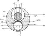
- 2 represents a cross-sectional view taken along line III-III of FIG. 1;
- Fig. 3 shows a cross-sectional view perpendicular to the longitudinal direction of a balloon catheter according to another embodiment of the invention;
- 5 illustrates another example of the cross-sectional view of FIG. 4;
- FIG. 1 depicts a side view of a balloon catheter according to one embodiment of the invention.
- FIG. 2 shows a cross-sectional view of the III-III cross-sectional view of FIG. 1 with the tube removed.
- FIG. 3 is a cross-sectional view taken along line III-III of FIG. 1, showing a mode in which the shaft and the restricting portion are made of different members.
- 4 and 5 are cross-sectional views perpendicular to the longitudinal axis direction of a balloon catheter according to another embodiment of the present invention, showing different modes in which the restricting portion is formed by the thick wall portion of the shaft.
- there is 3 to 5 show cross-sectional views of a state in which the guidewire is inserted through the first lumen.
- the balloon catheter 1 has a distal end and a proximal end in the longitudinal direction x.
- the proximal end is the end on the proximal side in the longitudinal axis direction x, and the proximal side refers to the extending direction of the balloon catheter 1, that is, the direction toward the user's hand side in the longitudinal axis direction x.
- the distal end is the end on the distal side in the longitudinal direction x, and the distal side refers to the direction opposite to the proximal side, that is, the direction toward the treatment target.
- a direction connecting a centroid P1 of the outer edge of the shaft 10 and a point on the outer edge of the shaft 10 in a cross section perpendicular to the longitudinal direction x is defined as a radial direction y.
- the balloon catheter 1 is a shaft 10 extending in the longitudinal direction x and having a lumen 100, the lumen 100 of the shaft 10 extending in the longitudinal direction x. and a first lumen 110 through which the guidewire 50 is inserted; a balloon 30 disposed distally of the shaft 10; and a tube 20 .
- the tube 20 is preferably a flow path for fluid that is introduced when the balloon 30 is inflated and is discharged when it is deflated. Fluid can be introduced or expelled using an indeflator (balloon pressurizer) to control inflation and deflation of balloon 30 .
- the fluid may be a pressurized fluid pressurized by a pump or the like.
- the balloon catheter 1 in which the balloon 30 is arranged at the distal portion of the shaft 10 has a configuration in which the distal portion of the tube 20 arranged in the second lumen 120 of the shaft 10 and the proximal end portion of the balloon 30 are connected. can do.
- the distal portion of the tube 20 and the proximal end portion of the balloon 30 are joined by bonding with an adhesive, welding, or a ring-shaped member at the place where the distal portion of the tube 20 and the proximal end portion of the balloon 30 overlap. It can be done by means such as attaching and crimping. Above all, it is preferable that the tube 20 and the balloon 30 are joined by welding. Since the tube 20 and the balloon 30 are welded together, even if the balloon 30 is repeatedly expanded or contracted, the joint with the tube 20 is unlikely to be released, and the joint strength between the tube 20 and the balloon 30 can be easily improved. .
- the first lumen 110 and the second lumen 120 communicate with each other in a cross section perpendicular to the longitudinal direction x.
- FIG. 2 shows a cross-sectional view with the tube 20 removed
- communication between the first lumen 110 and the second lumen 120 means that the first lumen 110 and the second lumen 120 are in communication with each other when the tube 20 is removed as shown in FIG. It means that the first lumen 110 and the second lumen 120 are connected.
- the outer wall of the tube 20 placed in the second lumen 120 abuts against the wall of the second lumen 120 .
- the tube 20 is arranged in the second lumen 120 so that there is no gap between it and the wall of the second lumen 120 . In this case, no space is formed between the wall of the second lumen 120 and the outer wall of the tube 20, but preferably the tube 20 is not fixed to the second lumen 120, and the tube 20 is connected to the second lumen of the shaft 10.
- 120 is a separate member.
- the tube 20 disposed in the second lumen 120 is a separate member from the shaft 10, unlike the case where the shaft has a guide wire lumen and an inflation lumen as a fluid flow path that are not in communication with each other. Therefore, the material of the tube 20 can be selected according to the type of fluid and the desired catheter conditions. In addition, by forming the shaft 10 and the tube 20 from different materials, the shaft 10 and the tube 20 can be manufactured to have different rigidity, so that the operability of the balloon catheter 1 can be adjusted according to the purpose. becomes possible.
- the shaft 10 does not have a boundary provided between the first lumen 110 and the second lumen 120 so that they are independent of each other. This allows communication between the first lumen 110 and the second lumen 120 . However, if the shaft 10 does not have a boundary between the first lumen 110 and the second lumen 120 for most of the longitudinal direction x, it may have a boundary for a portion of the longitudinal direction x. acceptable.
- the shaft 10 does not have a boundary between the first lumen 110 and the second lumen 120, so the first lumen 110 and the second lumen 120 are not separate lumens. Therefore, it can be said that the first lumen 110 and the second lumen 120 are parts of the lumen 100 of the shaft 10 . That is, the first lumen 110 is the portion of the lumen 100 of the shaft 10 through which the guide wire 50 is inserted, and the second lumen 120 is the portion of the lumen 100 of the shaft 10 in which the tube 20 is arranged.
- the first lumen 110 includes the centroid P1 of the outer edge of the shaft 10 in a cross section perpendicular to the longitudinal direction x. Since the first lumen 110 through which the guidewire 50 is inserted includes the centroid P1 of the outer edge of the shaft 10, the central axis of the shaft 10 and the central axis of the guidewire 50 inserted through the first lumen 110 are brought closer. Therefore, the pushability when pushing the balloon catheter 1 along the guide wire 50 can be improved.
- the shaft 10 has a restriction portion 40 that restricts movement of the tube 20 from the second lumen 120 to the first lumen 110.
- the regulating portion 40 may be provided as a member separate from the shaft 10 as shown in FIG. 3, or may be provided because the wall thickness of the shaft 10 is thick as described later. In either case, when the straight line connecting the centroid P1 of the outer edge of the shaft 10 and the centroid P2 of the outer edge of the tube 20 is L1, and the straight line perpendicular to the straight line L1 is L2, It is preferable that the lumen 100 is narrowed in the direction of the straight line L2 by the restricting portion 40 .
- the tube 20 placed in the second lumen 120 can be restricted from moving from the second lumen 120 to the first lumen 110 by the restricting portion 40 .
- the guide wire 50 inserted through the first lumen 110 and the tube 20 can be prevented from becoming entangled, and the slidability of the guide wire 50 can be improved.
- the lumen 100 of the shaft 10 refers to the space formed inside the restricting portion 40 of the shaft 10 when the tube 20 as shown in FIG. 2 is removed.
- the restricting portion 40 is provided on the inner wall of the shaft 10 . This is a portion formed inside the restricting portion 40 rather than a portion defined by the inner wall of the regulating portion 40 .
- the tube 20 is arranged in the second lumen 120 as shown in FIG. 3, the second lumen 120 is occupied by the tube 20, but when the tube 20 is removed as shown in FIG.
- a space formed inside the portion 40 will be described as a lumen 100 of the shaft 10 .
- the restricting portion 40 is preferably formed so that the cross-sectional shapes of the first lumen 110 and the second lumen 120 perpendicular to the longitudinal axis direction x each have a circular or oval shape. If the cross-sectional shape of the second lumen 120 is a shape that includes a part of a circular or oval shape, the outer shape of the tube 20 is also circular or oval shape, thereby facilitating manufacture of the balloon catheter 1 .
- the cross-sectional shape of the first lumen 110 is a shape including a part of a circular or oval shape, it becomes easy to insert the guide wire 50 through the first lumen 110, and the outer shape of the guide wire 50 is also circular or oval. By doing so, it becomes easier to reduce the resistance between the guide wire 50 and the wall of the first lumen 110 and improve the slidability of the guide wire 50 .
- FIG. 3 shows a mode in which the restricting portions 40 are provided on both sides in the radial direction y of the bore 100 of the shaft 10, but the restricting portions 40 may be provided only on one side in the radial direction y. .
- the restricting portion 40 are preferably provided on both sides in the radial direction y.
- the restricting portion 40 When the restricting portion 40 is provided as a separate member from the shaft 10 , it is preferable that the restricting portion 40 is fixed to the inner wall of the shaft 10 . Further, when the portion where the restricting portion 40 protrudes most inward in the radial direction y is defined as the most protruding portion 41, in the direction of the straight line L1, the first lumen 110 is located on one side of the most protruding portion 41 and the other side thereof. It is preferable that the restricting portion 40 is provided so that the second lumen 120 is formed at the end. That is, in the direction of the straight line L1, it is preferable that the first lumen 110 is formed on one side of a line segment L3 described later, and the second lumen 120 is formed on the other side of the line segment L3.
- a straight line connecting the centroid P1 and the centroid P2 of the outer edge of the tube 20 is L1
- a straight line perpendicular to the straight line L1 is L2.
- the width W41 of the lumen 100 of the shaft 10 at the location where the highest protrusion 41 is located is less than the length W20 defined by the outer edge of the tube 20.
- the restricting portion 40 is positioned at a first position S1 where the maximum diameter of the first lumen 110 is located and a second position S2 where the maximum diameter of the second lumen 120 is located in the direction parallel to the straight line L2. between, the wall thickness of the shaft 10 may be thicker than the wall thickness at the second position S2. With such a configuration, the restricting portion 40 can be formed integrally with the shaft 10, and the manufacturing of the balloon catheter 1 can be facilitated.
- FIG. 4 shows an example in which the restricting portion 40 is formed such that the cross-sectional shapes perpendicular to the longitudinal axis direction x of the first lumen 110 and the second lumen 120 are each substantially circular.
- the shape of 40 is not particularly limited as long as it satisfies the above requirements even if it is formed by increasing the wall thickness of shaft 10 .
- FIG. 4 shows an example in which the wall thickness of the shaft 10 is thicker than the wall thickness at the second position S2 on both sides in the radial direction y, so that the restriction portion 40 is formed.
- the wall thickness of the shaft 10 may be thicker than the wall thickness at the second position S2.
- the restricting portion 40 are preferably formed on both sides in the radial direction y.
- the shaft 10 is made of a material having both flexibility and biocompatibility. resin, vinyl chloride resin, silicone resin, natural rubber, and the like. These may use only 1 type and may use 2 or more types together. Among others, the material constituting the shaft 10 is preferably at least one of polyamide resin, polyolefin resin, and fluorine resin. As a result, the slipperiness of the surface of the shaft 10 can be enhanced, and the insertability of the balloon catheter 1 within the body cavity can be improved.
- the material configuring the shaft 10 can be referred to as the material configuring the restricting portion 40 .
- the material configuring restricting portion 40 is the same as the material configuring shaft 10 .
- means such as welding or adhesion can be used.
- the restricting portion 40 is formed by increasing the wall thickness of the shaft 10, a mold having a shape capable of forming the first lumen 110 and the second lumen 120 when forming the shaft 10 should be used.
- the shaft 10 having the restricting portion 40 can be manufactured.
- the balloon 30 includes an expansion portion, a proximal sleeve portion located proximal to the expansion portion, and a distal sleeve portion located distal to the expansion portion. It is preferable to have a part. With such a configuration, at least a portion of the proximal sleeve portion can be configured to be connected to the tube 20, and the fluid introduced through the tube 20 can expand the expanded portion to perform vasodilation or the like. Action can be taken.
- the proximal sleeve portion and the distal sleeve portion do not expand even in the expanded state of the expansion portion. Thereby, the connection between the balloon 30 and the tube 20 can be stabilized even when the balloon 30 is expanded.
- the expanded portion of the balloon 30 has a straight tube portion, a proximal tapered portion located proximal to the straight tube portion, and a distal tapered portion located distal to the straight tube portion. may be
- Examples of materials for forming the balloon 30 include polyolefin resins such as polyethylene, polypropylene, and ethylene-propylene copolymer; polyester resins such as polyethylene terephthalate and polyester elastomer; polyurethane resins such as polyurethane and polyurethane elastomer; and polyphenylene sulfide. system resin; polyamide system resin such as polyamide and polyamide elastomer; fluorine system resin; silicone system resin; natural rubber such as latex rubber, and the like. These may use only 1 type and may use 2 or more types together. Among them, polyamide-based resins, polyester-based resins, and polyurethane-based resins are preferably used.
- an elastomer resin from the viewpoint of thinning the balloon 30 and flexibility.
- polyamide-based resins nylon 12, nylon 11, and the like are suitable as the resin constituting the balloon 30, and nylon 12 is more suitable because it can be formed relatively easily in blow molding.
- the tube 20 is preferably a flow path for fluid that is introduced when the balloon 30 is inflated and is discharged when it is deflated.
- the cross-sectional shape of the tube 20 perpendicular to the longitudinal axis direction x is preferably circular, oval, or a shape including a portion thereof.
- the cross-sectional shape of the tube 20 perpendicular to the longitudinal axis direction x is preferably a shape along the cross-sectional shape of the second lumen 120 perpendicular to the longitudinal axis direction x. This makes it easy to bring the outer wall of the tube 20 into contact with the wall of the second lumen 120 in a cross section perpendicular to the longitudinal direction x.
- Materials constituting the tube 20 include resins such as polyimide resins, polyamide resins, PEEK resins, polyester resins, polyolefin resins, fluorine resins, vinyl chloride resins, polyurethane resins, and silicone resins. , nickel-titanium alloys, cobalt-chromium alloys, tungsten alloys, titanium, and stainless steel.
- the tube 20 is preferably made of metal. As long as the tube 20 is made of metal, the tube 20 allows the shaft 10 to move freely even though the shaft 10 does not have independent boundaries between the first lumen 110 and the second lumen 120 . It is possible to increase the rigidity. Thereby, the pushability of the balloon catheter 1 can be improved.
- the tube 20 is arranged in the second lumen 120 of the shaft 10, the tube 20 is arranged in a portion that is shifted to one side with respect to the central axis of the shaft 10, so that the rotational force applied on the hand side is far away.
- the torque transmissibility transmitted to the position side can be improved.
- the tube 20 is made of metal, it is easy to impart a predetermined or higher rigidity to the shaft 10 even if the outer shape of the shaft 10 is reduced, so that the trackability of the balloon catheter 1 can be improved. be.
- the shaft 10 and the tube 20 are preferably made of different materials. By forming the shaft 10 and the tube 20 from different materials, the shaft 10 and the tube 20 can be manufactured so as to have different rigidity. It is possible to adjust the operability according to the purpose.
- the tube 20 may be made of different materials in the longitudinal direction x.
- the central portion of tube 20 may be made of metal, and the distal and/or proximal ends of tube 20 may be made of resin.
- the central portion of the tube 20 in the longitudinal direction x is made of metal to increase the rigidity, while the ends of the tube 20 connected to the balloon 30 or the like are made of resin. 20 can be easily joined to the balloon 30 or the like.
- the rigidity of the tube 20 is preferably higher than that of the shaft 10.
- the rigidity of the tube 20 can be adjusted to the rigidity of the shaft 10. can be higher than Alternatively, even if the shaft 10 and the tube 20 are made of the same material, the rigidity of the tube 20 may differ from that of the shaft 10 due to structural differences such as making the wall thickness of the tube 20 thicker than that of the shaft 10 . can be made higher than Since the stiffness of the tube 20 is higher than the stiffness of the shaft 10, the pushability and torque transmissibility of the balloon catheter 1 can be improved.
- the balloon catheter 1 since the tube 20 has high rigidity, the balloon catheter 1 can be configured to have a predetermined or higher rigidity even if the outer shape of the shaft 10 is reduced, which is advantageous in improving the trackability of the balloon catheter 1. be.
- the rigidity of the tube 20 is preferably lower than that of the shaft 10.
- the rigidity of the tube 20 can be adjusted to the rigidity of the shaft 10 by forming the tube 20 from a resin having lower rigidity than the resin forming the shaft 10 or by making the wall thickness of the tube 20 thinner than the wall thickness of the shaft 10 . can be made lower than Since the rigidity of the tube 20 is lower than the rigidity of the shaft 10, the flexibility of the balloon catheter 1 can be improved and the trackability can be improved.
- the length of the first lumen 110 is on the straight line L1.
- length W 110 is less than or equal to twice the length W 50 defined by the outer edge of guidewire 50 .
- the length W110 of the first lumen 110 is more preferably 1.7 times or less the length W50 , and even more preferably 1.4 times or less.
- the lower limit of the length W110 of the first lumen 110 to the length W50 is not particularly limited as long as the guidewire 50 can slide in the first lumen 110, but is preferably 1.1 times or more.
- Twice or more is more preferable.
- the size of the space formed between the outer edge of the guidewire 50 and the wall of the first lumen 110 is less than or equal to the diameter of the guidewire 50. Therefore, it becomes easy for the guide wire 50 to exist on the side of the centroid P1 of the first lumen 110 including the centroid P1, and it becomes easy to bring the central axis of the shaft 10 and the central axis of the guide wire 50 closer together. . As a result, it is possible to more easily improve the pushability when pushing the balloon catheter 1 along the guide wire 50 .
- the shaft 10 in a cross section perpendicular to the longitudinal axis direction x, when the straight line connecting the centroid P1 and the centroid P2 of the outer edge of the tube 20 is L1, and the straight line perpendicular to the straight line L1 is L2, the shaft 10 has a third position S3 where the lumen 100 of the shaft 10 has the minimum width by the regulation part 40 in the direction parallel to the straight line L2.
- a line segment parallel to the straight line L2 is L3
- the outer edge of the tube 20 is in contact with the line segment L3, or has a portion on the opposite side of the centroid P2 of the outer edge of the tube 20 with respect to the line segment L3. preferably.
- the outer edge of the tube 20 has a portion that is in contact with the line segment L3 or protrudes toward the first lumen 110 with respect to the line segment L3. Since the position where the inner cavity 100 of the shaft 10 becomes the minimum width by the restricting portion 40 in the direction parallel to the straight line L2 is the position where the most protruding portion 41 of the restricting portion 40 exists, the line segment L3 is the length of the shaft 10. A line segment connecting the most projecting portion 41 of the restricting portion 40 provided on one side with respect to the straight line L1 of the lumen 100 and the most projecting portion 41 of the restricting portion 40 provided on the other side with respect to the straight line L1. It can be said that there is.
- both the tube 20 and the guide wire 50 have a circular outer shape in a cross section perpendicular to the longitudinal axis direction x.
- the guide wire 50 inserted through the first lumen 110 and the tube 20 can make point contact in a cross section perpendicular to the longitudinal axis direction x, so that the guide wire 50 slides in the first lumen 110. The resistance when moving is reduced, and the slidability of the guide wire 50 can be improved.
- the restricting portion 40 is provided only on one side with respect to the straight line L1, a straight line L2 connecting the restricting portion 40 on one side and the wall of the bore 100 of the shaft 10 on the other side at the third position S3.
- a straight line L2 connecting the restricting portion 40 on one side and the wall of the bore 100 of the shaft 10 on the other side at the third position S3.
- the outer edge of the tube 20 is in contact with the line segment L3 or has a portion that exists on the opposite side of the centroid P2 of the outer edge of the tube 20 with respect to the line segment L3. is preferred.
- the shaft 10 has a regulating portion 40 formed between the first position S1 and the second position S2 by making the wall thickness of the shaft 10 thicker than the wall thickness at the second position S2.
- the restricting portion 40 is provided by a separate member as shown in FIG. A position where 100 has a minimum width can be defined as a third position S3. It is preferable to have a portion that is in contact with the line segment L3 or located on the opposite side of the centroid P2 of the outer edge of the tube 20 with respect to the line segment L3.
- the restricting portion 40 which is a separate member, is provided only on one side of the straight line L1
- the restricting portion 40 on one side and the wall of the bore 100 of the shaft 10 on the other side are separated at the third position S3.
- the outer edge of the tube 20 has a portion that is in contact with the line segment L3 or exists on the opposite side of the centroid P2 of the outer edge of the tube 20 with respect to the line segment L3. preferably.
- the shaft 10 has a third position S3 where the lumen 100 of the shaft 10 has the minimum width by the regulation part 40 in the direction parallel to the straight line L2.
- the outer edge of the tube 20 preferably does not have a portion on the opposite side of the centroid P2 with respect to the line segment L3. That is, it is preferable that the outer edge of the tube 20 does not have a portion protruding toward the first lumen 110 with respect to the line segment L3.
- the first lumen 110 is formed in a circular shape in a cross section perpendicular to the longitudinal axis direction x, and the portion of the tube 20 facing the first lumen 110 is recessed. It preferably has an oval shape, and the second lumen 120 preferably has a shape that follows the outer shape of the tube 20 .
- the center of the guide wire 50 inserted through the first lumen 110 can be positioned closer to the centroid P1 of the outer edge of the shaft 10 in a cross section perpendicular to the longitudinal axis direction x. 10 and the central axis of the guide wire 50 can be brought closer, and pushability when pushing the balloon catheter 1 along the guide wire 50 can be improved more easily.
- the restricting portion 40 is provided only on one side with respect to the straight line L1, a straight line L2 connecting the restricting portion 40 on one side and the wall of the bore 100 of the shaft 10 on the other side at the third position S3.
- a straight line L2 connecting the restricting portion 40 on one side and the wall of the bore 100 of the shaft 10 on the other side at the third position S3.
- the outer edge of the tube 20 does not have a portion that is in contact with the line segment L3 or exists on the opposite side of the centroid P2 of the outer edge of the tube 20 with respect to the line segment L3. is preferred.
- the inner lumen 100 of the shaft 10 is formed between the first position S1 and the second position S2 so that the wall thickness of the shaft 10 is thicker than the wall thickness at the second position S2. 3, even if the restricting portion 40 is provided by a separate member as shown in FIG. 3, the shaft A third position S3 can be defined as the position where the lumen 100 of 10 has the minimum width.
- the outer edge of tube 20 does not have a portion lying on the opposite side of centroid P2 of the outer edge of tube 20 with respect to line L3.
- the restricting portion 40 which is a separate member, is provided only on one side of the straight line L1
- the restricting portion 40 on one side and the wall of the bore 100 of the shaft 10 on the other side are separated at the third position S3.
- the outer edge of the tube 20 has a portion that is in contact with the line segment L3 or exists on the opposite side of the centroid P2 of the outer edge of the tube 20 with respect to the line segment L3. preferably not.
- a hydrophilic coating or a hydrophobic coating is preferably applied to the portion of the outer wall of the tube 20 facing the first lumen 110 .
- the portion of the outer wall of the tube 20 facing the first lumen 110 is a portion that may come into contact with the guide wire 50 inserted through the first lumen 110. Therefore, by coating this portion, the guide wire 50 slidability can be improved.
- Hydrophilic coating or hydrophobic coating can be performed by immersing the tube 20 in a hydrophilic coating agent or a hydrophobic coating agent, applying a hydrophilic coating agent or a hydrophobic coating agent to the outer wall of the tube 20, or applying a hydrophilic coating agent or a hydrophobic coating agent to the outer wall of the tube 20. It can be applied by coating with a hydrophilic coating agent or a hydrophobic coating agent.
- a coating agent that can reduce the resistance with the material may be selected.
- Hydrophobic coating agents used for the portion of the outer wall of tube 20 facing first lumen 110 include polytetrafluoroethylene (PTFE), fluoroethylene propylene (FEP), silicone oil, hydrophobic urethane resin, carbon coat, A diamond coat, a diamond-like carbon (DLC) coat, a ceramic coat, and a substance terminated with an alkyl group or a perfluoroalkyl group and having a small surface free energy can be used.
- PTFE polytetrafluoroethylene
- FEP fluoroethylene propylene
- silicone oil silicone oil
- hydrophobic urethane resin carbon coat
- a diamond coat a diamond-like carbon (DLC) coat
- ceramic coat a substance terminated with an alkyl group or a perfluoroalkyl group and having a small surface free energy
- the wall of the lumen 100 of the shaft 10 forming the first lumen 110 is preferably coated with a hydrophilic coating or a hydrophobic coating.
- the wall of the lumen 100 of the shaft 10 that forms the first lumen 110 is a portion that may come into contact with the guide wire 50 that is passed through the first lumen 110.
- the slidability of the wire 50 can be enhanced.
- Hydrophilic coating or hydrophobic coating is applied by immersing the shaft 10 in a hydrophilic coating agent or a hydrophobic coating agent, applying a hydrophilic coating agent or a hydrophobic coating agent to the wall of the lumen 100 of the shaft 10, or applying a hydrophilic coating agent or a hydrophobic coating agent to the shaft.
- a hydrophilic or hydrophobic coating that can be used on the wall of the lumen 100 of the shaft 10 that forms the first lumen 110 is a hydrophilic coating that can be applied to the portion of the outer wall of the tube 20 that faces the first lumen 110 .
- the inner wall of the tube 20 is coated with a hydrophilic coating or a hydrophobic coating.
- Hydrophilic coating or hydrophobic coating can be performed by immersing the tube 20 in a hydrophilic coating agent or a hydrophobic coating agent, applying a hydrophilic coating agent or a hydrophobic coating agent to the inner wall of the tube 20, or coating the inner wall of the tube 20. It can be applied by coating with a hydrophilic coating agent or a hydrophobic coating agent.
- a coating agent that can reduce resistance to the fluid may be selected. This allows fluid to easily pass through the lumen of tube 20 .
- a hydrophilic coating agent or a hydrophobic coating agent that can be used for the inner wall of the tube 20 can refer to a hydrophilic coating agent or a hydrophobic coating agent that can be applied to a portion of the outer wall of the tube 20 facing the first lumen 110 .
- the balloon catheter 1 may have a hub 4 on the proximal side of the shaft 10, and the hub 4 may be provided with the fluid injection section 2 and the guidewire insertion section 3. . Since the balloon catheter 1 has a hub 4 having a fluid injection section 2 and a guidewire insertion section 3, it is possible to supply fluid to the inside of the balloon 30 to expand or contract the balloon 30 and to operate the guidewire 50. can be easily done.
- the so-called over-the-wire type in which the guide wire 50 is inserted from the distal side to the proximal side of the shaft 10 as shown in FIG. It can also be applied to a so-called rapid exchange type in which the guide wire 50 is inserted halfway from the side to the proximal side.
- the joint between the shaft 10 and the hub 4 can be performed, for example, by means of adhesion, welding, or the like. Above all, it is preferable that the shaft 10 and the hub 4 are joined by adhesion.
- the shaft 10 and the hub 4 are configured such that, for example, the shaft 10 is made of a highly flexible material and the hub 4 is made of a highly rigid material. Since the joint strength can be increased even if the materials are different, the degree of freedom in selecting the materials that constitute the shaft 10 and the hub 4 can be improved.
- the distal end of the balloon catheter 1 is preferably provided with a tip member.
- a tip member By providing the tip member, it is possible to prevent the distal end of the balloon catheter 1 from being damaged when it comes into contact with a biological organ such as a blood vessel wall or a lumen wall of an organ.
- Balloon catheter 2 Fluid injection part 3: Guide wire insertion part 4: Hub 10: Shaft 20: Tube 30: Balloon 40: Regulating part 41: Most protruding part 50: Guide wire 100: Lumen of shaft 110: First Lumen 120: Second lumen P1: Centroid of outer edge of shaft P2: Centroid of outer edge of tube L1: Straight line connecting P1 and P2: Straight line L2 perpendicular to L1: Line segment S1: First position S2: Second 2nd position S3: 3rd position W20 : Length W41 defined by the outer edge of the tube: Width W50 of the lumen of the shaft at the point of maximum protrusion: Length W110 defined by the outer edge of the guidewire: First lumen length x: longitudinal axis direction y: radial direction
Landscapes
- Health & Medical Sciences (AREA)
- Life Sciences & Earth Sciences (AREA)
- Heart & Thoracic Surgery (AREA)
- Engineering & Computer Science (AREA)
- Biophysics (AREA)
- Pulmonology (AREA)
- Anesthesiology (AREA)
- Biomedical Technology (AREA)
- Hematology (AREA)
- Animal Behavior & Ethology (AREA)
- General Health & Medical Sciences (AREA)
- Public Health (AREA)
- Veterinary Medicine (AREA)
- Child & Adolescent Psychology (AREA)
- Media Introduction/Drainage Providing Device (AREA)
Abstract
L'invention fournit un cathéter à ballon qui présente une aptitude à la poussée améliorée, et qui permet de faire coulisser de manière satisfaisante un fil-guide. Plus précisément, l'invention concerne un cathéter à ballon qui possède : un arbre (10) dans lequel une cavité (100) contient une seconde lumière (120), et une première lumière (110) pour insertion du fil-guide (50) ; un ballon disposé sur une partie distale de l'arbre (10) ; et un tube (20) disposé dans la seconde lumière (120). Dans un plan transversal perpendiculaire à la direction longitudinale, la première lumière (110) et la seconde lumière (120) communiquent, une paroi externe du tube (20) est en contact avec une paroi de la seconde lumière (120), la première lumière (110) inclut le centre (P1) d'un bord externe de l'arbre (10), et l'arbre (10) possède une partie régulation (40) qui assure une régulation de sorte que le tube (20) ne peut pas se déplacer de la seconde lumière (120) vers la première lumière (110).
Applications Claiming Priority (2)
| Application Number | Priority Date | Filing Date | Title |
|---|---|---|---|
| JP2022023391 | 2022-02-18 | ||
| JP2022-023391 | 2022-02-18 |
Publications (1)
| Publication Number | Publication Date |
|---|---|
| WO2023157535A1 true WO2023157535A1 (fr) | 2023-08-24 |
Family
ID=87578376
Family Applications (1)
| Application Number | Title | Priority Date | Filing Date |
|---|---|---|---|
| PCT/JP2023/001211 WO2023157535A1 (fr) | 2022-02-18 | 2023-01-17 | Cathéter à ballon |
Country Status (1)
| Country | Link |
|---|---|
| WO (1) | WO2023157535A1 (fr) |
Citations (6)
| Publication number | Priority date | Publication date | Assignee | Title |
|---|---|---|---|---|
| WO1999038557A1 (fr) * | 1998-01-30 | 1999-08-05 | Kaneka Corporation | Sonde a ballonnet, tige de sonde associee et procede de production de ballonnet |
| JP2007530163A (ja) * | 2004-03-24 | 2007-11-01 | メドトロニック ヴァスキュラー インコーポレイテッド | カテーテルの遷移部 |
| JP2010119776A (ja) * | 2008-11-21 | 2010-06-03 | Kaneka Corp | 異形断面を持つカテーテル支持体 |
| JP2016187441A (ja) * | 2015-03-30 | 2016-11-04 | フクダ電子株式会社 | カテーテル |
| WO2020128633A2 (fr) * | 2018-12-21 | 2020-06-25 | Crannmed Limited | Cathéter d'occlusion à ballonnet |
| JP2022055329A (ja) * | 2020-09-28 | 2022-04-07 | 株式会社東海メディカルプロダクツ | バルーン付きカテーテル |
-
2023
- 2023-01-17 WO PCT/JP2023/001211 patent/WO2023157535A1/fr unknown
Patent Citations (6)
| Publication number | Priority date | Publication date | Assignee | Title |
|---|---|---|---|---|
| WO1999038557A1 (fr) * | 1998-01-30 | 1999-08-05 | Kaneka Corporation | Sonde a ballonnet, tige de sonde associee et procede de production de ballonnet |
| JP2007530163A (ja) * | 2004-03-24 | 2007-11-01 | メドトロニック ヴァスキュラー インコーポレイテッド | カテーテルの遷移部 |
| JP2010119776A (ja) * | 2008-11-21 | 2010-06-03 | Kaneka Corp | 異形断面を持つカテーテル支持体 |
| JP2016187441A (ja) * | 2015-03-30 | 2016-11-04 | フクダ電子株式会社 | カテーテル |
| WO2020128633A2 (fr) * | 2018-12-21 | 2020-06-25 | Crannmed Limited | Cathéter d'occlusion à ballonnet |
| JP2022055329A (ja) * | 2020-09-28 | 2022-04-07 | 株式会社東海メディカルプロダクツ | バルーン付きカテーテル |
Similar Documents
| Publication | Publication Date | Title |
|---|---|---|
| US7465311B2 (en) | Catheter having an improved distal tip | |
| JP4985398B2 (ja) | カテーテル | |
| JP5061614B2 (ja) | カテーテル | |
| US7727187B2 (en) | Scored catheter device | |
| US6436090B1 (en) | Multi lumen catheter shaft | |
| WO2021049282A1 (fr) | Méthode de production de cathéter à ballonnet | |
| JP4914281B2 (ja) | カテーテル | |
| WO2022102766A1 (fr) | Ballonnet pour cathéter à ballonnet | |
| US20060206137A1 (en) | Balloon structure and balloon catheter | |
| JP5066992B2 (ja) | バルーンカテーテル | |
| WO2023157535A1 (fr) | Cathéter à ballon | |
| WO2023157533A1 (fr) | Cathéter à ballonnet | |
| EP4017568A1 (fr) | Cathéters et procédés de fabrication et d'utilisation | |
| WO2023157534A1 (fr) | Cathéter à ballon | |
| WO2021049261A1 (fr) | Procédé de fabrication de cathéter à ballonnet | |
| JP4914282B2 (ja) | 押圧性を備えたカテーテル | |
| CN115335103A (zh) | 球囊导管 | |
| WO2016158584A1 (fr) | Cathéter de dilatation et procédé de fabrication de cathéter de dilatation | |
| WO2021125103A1 (fr) | Cathéter à ballonnet | |
| WO2023079906A1 (fr) | Ballonnet pour cathéter à ballonnet | |
| JP2022121902A (ja) | カテーテル | |
| US20230211131A1 (en) | Balloon catheters and methods of manufacture and use | |
| CN116457048A (zh) | 球囊导管用球囊 | |
| JP2008264119A (ja) | 押圧性を備えたカテーテル | |
| JP2000233026A (ja) | 医療用カテーテル |
Legal Events
| Date | Code | Title | Description |
|---|---|---|---|
| 121 | Ep: the epo has been informed by wipo that ep was designated in this application |
Ref document number: 23756063 Country of ref document: EP Kind code of ref document: A1 |
|
| ENP | Entry into the national phase |
Ref document number: 2024501031 Country of ref document: JP Kind code of ref document: A |