WO2023079906A1 - Ballonnet pour cathéter à ballonnet - Google Patents
Ballonnet pour cathéter à ballonnet Download PDFInfo
- Publication number
- WO2023079906A1 WO2023079906A1 PCT/JP2022/037780 JP2022037780W WO2023079906A1 WO 2023079906 A1 WO2023079906 A1 WO 2023079906A1 JP 2022037780 W JP2022037780 W JP 2022037780W WO 2023079906 A1 WO2023079906 A1 WO 2023079906A1
- Authority
- WO
- WIPO (PCT)
- Prior art keywords
- balloon
- proximal
- distal
- cross
- section
- Prior art date
Links
Images


Classifications
-
- A—HUMAN NECESSITIES
- A61—MEDICAL OR VETERINARY SCIENCE; HYGIENE
- A61M—DEVICES FOR INTRODUCING MEDIA INTO, OR ONTO, THE BODY; DEVICES FOR TRANSDUCING BODY MEDIA OR FOR TAKING MEDIA FROM THE BODY; DEVICES FOR PRODUCING OR ENDING SLEEP OR STUPOR
- A61M25/00—Catheters; Hollow probes
- A61M25/10—Balloon catheters
Definitions
- the present invention relates to balloons for balloon catheters.
- Angioplasty which uses a balloon catheter to dilate the stenosis.
- Angioplasty is a widely practiced minimally invasive therapy that does not require an open chest like bypass surgery.
- the balloon catheter is inserted into the body cavity with the balloon deflated and delivered to the treatment site through the body cavity.
- the delivery of the balloon is controlled by transmitting manipulation from the proximal side to the distal side where the balloon is located.
- it is required that the insertion into the body cavity is easy, and that the operation from the proximal side is easily transmitted to the distal side (high pushability).
- a fluid is introduced into the lumen of the balloon to expand the balloon, the pressure of the fluid causes the balloon to stretch in an undesired direction or break.
- Patent Document 1 discloses a balloon catheter in which the bonding strength between the balloon and the outer shaft is improved without increasing the outer diameter of the bonding portion between the balloon and the outer shaft.
- Balloon catheters are required not only to have high pushability and balloon strength, but also to have the ability to smoothly pass through body cavities and the ability to flexibly progress through tortuous body cavities (trackability).
- conventional balloon catheters are insufficient to simultaneously improve strength, smooth insertion, and improve trackability. Accordingly, it is an object of the present invention to provide a balloon for a balloon catheter that can be smoothly inserted into a body cavity and has improved trackability and pushability while preventing the balloon from stretching or breaking in undesired directions by increasing the strength of the balloon. aim.
- a first balloon for a balloon catheter which has solved the above problems, is as follows. [1] A straight tube portion, a proximal tapered portion located proximal to the straight tube portion, and a proximal sleeve portion located proximal to the proximal tapered portion a distal tapered portion located distal to the straight tube portion; and a distal sleeve portion located distal to the distal tapered portion. a balloon body having an outer surface and an inner surface; and a protrusion projecting radially outward from the outer surface of the balloon body and extending in the longitudinal direction of the balloon body.
- the protruding portion provided on the straight tube portion has a base end connected to the outer surface of the balloon body and a base end extending from the base end in the radial direction and a tip that is the outer end of the protrusion in the radial direction, and satisfies at least one of the following (1) and (2).
- the protruding portion provided on the proximal sleeve portion is inclined in the first direction or the second direction in the circumferential direction of the balloon body, and the width of the proximal end
- the angle between the straight line connecting the midpoint of the direction and the tip and the perpendicular to the base is 45° or more.
- the protruding portion provided on the distal sleeve portion is inclined in the first direction or the second direction in the circumferential direction of the balloon body, and the width of the proximal end
- the angle between the straight line connecting the midpoint of the direction and the tip and the perpendicular to the base is 45° or more.
- the strength of the balloon is increased by having the protruding portion to prevent the balloon from being stretched in an undesired direction or being damaged, and the balloon is at the leading edge when the balloon is advanced or retracted.
- the projections provided on the distal sleeve portion and/or the proximal sleeve portion are tilted in the first direction or the second direction in the circumferential direction of the balloon body, so that the fallen projections act like cushions. It is possible to provide a balloon for a balloon catheter that can be smoothly inserted into a body cavity and has improved trackability.
- the projections provided on the distal sleeve portion and/or the proximal sleeve portion are tilted in the first direction or the second direction in the circumferential direction of the balloon body, thereby reducing the projections themselves. It is possible to reduce the outer diameter of the balloon, and achieve both the strength of the balloon and the ease of insertion into the body cavity.
- Preferred aspects of the first balloon catheter balloon according to the embodiment of the present invention are as follows.
- the angle formed by the connecting straight line and the perpendicular to the base end is 45° or more,
- the proximal sleeve portion has an inner protrusion that protrudes radially inward from the inner surface of the balloon body and extends in the longitudinal direction.
- the protruding portion of the distal sleeve portion is tilted in the first direction or the second direction, and the midpoint of the proximal end in the width direction and the distal end are aligned.
- the angle formed by the connecting straight line and the perpendicular to the base end is 45° or more,
- the distal sleeve portion has an inner protrusion projecting radially inwardly beyond the inner surface of the balloon body and extending in the longitudinal direction.
- the protruding portion of the proximal sleeve portion is tilted in the first direction or the second direction, and the middle point in the width direction of the proximal end and the distal end are aligned.
- the angle formed by the connecting straight line and the perpendicular to the base end is 45° or more.
- the protruding portion of the proximal side taper portion is inclined in the first direction or the second direction, and a straight line connecting the midpoint of the proximal end in the width direction and the distal end.
- the angle between the base end and the normal line is 30° or more.
- the protruding portion of the distal sleeve portion is inclined in the first direction or the second direction, and the midpoint of the proximal end in the width direction and the distal end are aligned.
- the angle formed by the connecting straight line and the perpendicular to the base end is 45° or more.
- the protruding portion of the distal tapered portion is tilted in the first direction or the second direction, and a straight line connecting the midpoint of the proximal end in the width direction and the distal end
- the angle between the base end and the normal line is 30° or more.
- the angle formed by the perpendicular to the base end is 30° or more
- the proximal sleeve portion and the proximal tapered portion have an inner projection that projects radially inward from the inner surface of the balloon body and extends in the longitudinal direction. .
- the protruding portion of the distal sleeve portion is inclined in the first direction or the second direction, and the midpoint of the proximal end in the width direction and the distal end are aligned.
- the angle formed by the connecting straight line and the perpendicular to the base end is 45° or more, In the cross section in the radial direction, the protruding portion of the distal tapered portion is tilted in the first direction or the second direction, and a straight line connecting the midpoint of the proximal end in the width direction and the distal end
- the angle formed by the perpendicular to the base end is 30° or more,
- the distal sleeve portion and the distal tapered portion have an inner protrusion projecting radially inwardly beyond the inner surface of the balloon body and extending in the longitudinal direction. .
- a second balloon for a balloon catheter which has solved the above problems, is as follows. [5] A straight pipe portion, a proximal tapered portion located proximal to the straight pipe portion, and a proximal sleeve portion located proximal to the proximal tapered portion a distal tapered portion located distal to the straight tube portion; and a distal sleeve portion located distal to the distal tapered portion. a balloon body having an outer surface and an inner surface; and a protrusion projecting radially outward from the outer surface of the balloon body and extending in the longitudinal direction of the balloon body.
- the protruding portion provided on the straight tube portion has a base end connected to the outer surface of the balloon body and a base end extending from the base end in the radial direction and a tip that is the outer end of the protrusion in the radial direction,
- a balloon for a balloon catheter that satisfies at least one of the following (9) and (10).
- the projecting portion of the proximal side taper portion is inclined in the first or second circumferential direction of the balloon body, and is at the midpoint of the proximal end in the width direction. and the tip, and the perpendicular to the base end forms an angle of 30° or more.
- the projecting portion of the distal tapered portion is inclined in the first or second circumferential direction of the balloon body, and is at the midpoint of the proximal end in the width direction. and the tip, and the perpendicular to the base end forms an angle of 30° or more.
- the strength of the balloon is increased by having the projecting portion, and the balloon is prevented from being stretched in an undesired direction or damaged, and is the first balloon when the balloon is advanced or retracted.
- the projections provided on the distal side taper portion and/or the proximal side taper portion are tilted in the first direction or the second direction in the circumferential direction of the balloon body, so that the tilted projections act like cushions.
- the projections provided on the distal side taper portion and/or the proximal side taper portion are tilted in the first direction or the second direction in the circumferential direction of the balloon body, so that the projections themselves can be reduced. Since the outer diameter of the balloon can be suppressed without the need, it is possible to achieve both the strength of the balloon and the ease of insertion into the body cavity.
- (11) In the cross section in the radial direction, the projecting portion of the proximal side taper portion is inclined in the first direction or the second direction, and the midpoint in the width direction of the base end and the tip end are inclined.
- the angle formed by the connecting straight line and the perpendicular to the base end is 30° or more
- the proximal tapered portion has an inner protrusion that protrudes radially inward from the inner surface of the balloon body and extends in the longitudinal direction.
- the protruding portion of the distal tapered portion is inclined in the first direction or the second direction, and the midpoint of the proximal end in the width direction and the distal end
- the angle formed by the connecting straight line and the perpendicular to the base end is 30° or more
- the distal taper has an inner projection that projects radially inwardly beyond the inner surface of the balloon body and extends in the longitudinal direction.
- the projecting portion of the proximal side taper portion is inclined in the first direction or the second direction, and the middle point in the width direction of the base end and the tip end are inclined.
- the angle formed by the connecting straight line and the perpendicular to the base end is 30° or more,
- the projecting portion is tilted in the first direction or the second direction over the entire longitudinal axis direction of the proximal side tapered portion.
- the protruding portion of the distal tapered portion is inclined in the first direction or the second direction, and the midpoint of the base end in the width direction and the tip end are inclined.
- the angle formed by the connecting straight line and the perpendicular to the base end is 30° or more,
- the projecting portion is tilted in the first direction or the second direction over the entire longitudinal axis direction of the distal tapered portion.
- the projecting portion of the proximal side taper portion is inclined in the first direction or the second direction, and the midpoint in the width direction of the base end and the tip end are inclined.
- the angle formed by the connecting straight line and the perpendicular to the base end is 30° or more, The projecting portion is tilted in the first direction or the second direction at least partially in the longitudinal axis direction of the proximal side tapered portion.
- the protruding portion of the distal tapered portion is inclined in the first direction or the second direction, and the midpoint of the proximal end in the width direction and the distal end.
- the angle formed by the connecting straight line and the perpendicular to the base end is 30° or more, The projecting portion is tilted in the first direction or the second direction at least partially in the longitudinal axis direction of the distal tapered portion.
- the protruding portion enhances the strength of the balloon and prevents the balloon from stretching in an undesired direction or from being damaged. Since the protruding portion is tilted in the first direction or the second direction in the circumferential direction of the balloon body, the tilted protruding portion acts like a cushion, so that it can be smoothly inserted into the body cavity and trackability is improved. It is possible to provide a balloon for a balloon catheter with improved performance. In addition, since the protruding portion is tilted in the first direction or the second direction in the circumferential direction of the balloon body, the outer diameter of the balloon can be suppressed without shrinking the protruding portion itself. It is possible to achieve both the ease of insertion of the
- FIG. 1 depicts a side view of a balloon catheter according to one embodiment of the present invention
- FIG. 2 represents a cross-sectional view along line II-II of FIG. 1
- FIG. Figure 3 shows a cross-sectional view of the balloon shown in Figure 2 in a deflated state
- 2 represents a cross-sectional view along line IV-IV of FIG. 1
- FIG. Figure 5 shows a cross-sectional view of the balloon shown in Figure 4 in a deflated state
- 2 represents a cross-sectional view along the line VI-VI of FIG. 1
- FIG. FIG. 7 represents a variant of FIG. 6
- Fig. 3 depicts a cross-sectional view of a balloon according to another embodiment of the present invention
- FIG. 1 depicts a side view of a balloon catheter according to one embodiment of the present invention
- FIG. 2 represents a cross-sectional view along line II-II of FIG. 1
- FIG. Figure 3 shows a cross-sectional view of the balloon shown in Figure 2
- FIG. 4 depicts a cross-sectional view of a balloon according to yet another embodiment of the present invention
- FIG. 4 depicts a cross-sectional view of a balloon according to yet another embodiment of the present invention
- FIG. 1B depicts a perspective view of a parison prior to inflation, according to an embodiment of the present invention
- a first balloon for a balloon catheter includes a straight tube portion, a proximal tapered portion located proximal to the straight tube portion, and a tapered portion located proximal to the proximal tapered portion.
- a proximal sleeve portion located on the lateral side, a distal taper portion located distal to the straight tube portion, and a distal taper portion located distal to the distal taper portion.
- a balloon for a balloon catheter comprising: a side sleeve portion; a balloon body having an outer surface and an inner surface; and a protrusion provided on the straight tube portion, in a radial cross section, has a proximal end connected to the outer surface of the balloon body and a diameter larger than the proximal end. and a tip that is positioned outward in the direction and is the radially outer end of the protrusion, and satisfies at least one of the following (1) and (2).
- the projecting portion provided on the proximal sleeve portion is inclined in the first or second circumferential direction of the balloon body, and is aligned with the midpoint in the width direction of the proximal end.
- the angle between the straight line connecting the tip and the perpendicular to the base is 45° or more.
- the protruding portion provided on the distal sleeve portion is inclined in the first or second circumferential direction of the balloon body, and is aligned with the midpoint in the width direction of the proximal end.
- the angle between the straight line connecting the tip and the perpendicular to the base is 45° or more.
- the first balloon for a balloon catheter has a protruding portion to increase the strength of the balloon and prevent the balloon from stretching in an undesired direction and from being damaged, while advancing the balloon.
- the protruding portion provided on the distal sleeve portion and/or the proximal sleeve portion, which is the leading portion when retracted, is tilted in the first or second direction in the circumferential direction of the balloon body. Since the protruding portion functions like a cushion, it is possible to provide a balloon for a balloon catheter that can be smoothly inserted into a body cavity and has improved trackability.
- the projections provided on the distal sleeve portion and/or the proximal sleeve portion are tilted in the first direction or the second direction in the circumferential direction of the balloon body, thereby reducing the projections themselves. Since the outer diameter of the balloon can be suppressed without the need, it is possible to achieve both the strength of the balloon and the ease of insertion into the body cavity.
- FIG. 1 depicts a side view of a balloon catheter according to one embodiment of the present invention.
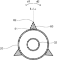
- FIG. 2 is a cross-sectional view taken along line II-II of FIG. 1, showing a cross-sectional view of the straight tube portion of the balloon of the balloon catheter shown in FIG. 1 in an inflated state.
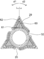
- FIG. 3 represents a cross-sectional view of the extension shown in FIG. 2 in a contracted state.
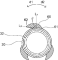
- FIG. 4 represents a cross-sectional view along line IV-IV of FIG. 1, and represents a cross-sectional view of the distal tapered portion of the balloon of the balloon catheter shown in FIG. 1 in an expanded state.
- FIG. 1 depicts a side view of a balloon catheter according to one embodiment of the present invention.
- FIG. 2 is a cross-sectional view taken along line II-II of FIG. 1, showing a cross-sectional view of the straight tube portion of the balloon of the balloon catheter shown in FIG. 1 in an inflated state.
- FIG. 3 represents a cross-sectional view of
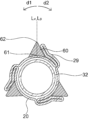
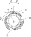
- FIG. 5 depicts a cross-sectional view of the distal taper shown in FIG. 4 in a contracted state.
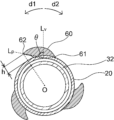
- FIG. 6 represents a cross-sectional view along line VI-VI of FIG. 1 and represents a cross-sectional view of the distal sleeve portion of the balloon of the balloon catheter shown in FIG.
- FIG. 7 represents a variant of FIG. 8 to 10 represent cross-sectional views of balloon catheter balloons according to different embodiments of the present invention
- FIG. 8 represents a cross-sectional view of a distal sleeve portion
- FIGS. FIG. 9 shows a cross-sectional view of a more distal distal taper
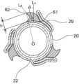
- FIG. 10 shows a cross-sectional view of a more proximal distal taper.
- the balloon for balloon catheter may be simply referred to as "balloon".
- the proximal side refers to the direction toward the user's hand side with respect to the extending direction of the balloon catheter 1 or the longitudinal direction of the shaft 3, and the distal side refers to the opposite direction to the proximal side, that is, the treatment. Point in the direction of the target.
- the longitudinal axis direction of the balloon catheter 1 is preferably the same as the longitudinal axis direction x of the balloon body 20 . Further, in this specification, even members other than elongated members are described as having the same longitudinal axis direction x.
- the radial direction y of the balloon body 20 is a direction perpendicular to the longitudinal axis direction x and a direction connecting the center of the balloon body 20 and a point on the outer edge of the balloon body 20 in a cross section perpendicular to the longitudinal axis direction x.
- the circumferential direction z of the balloon body 20 is the direction along the outer edge of the expanded balloon body 20 in the cross section in the radial direction y.
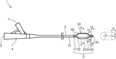
- the balloon catheter 1 has a shaft 3 and a balloon 2 provided at the distal end of the shaft 3.
- Balloon catheter 1 is configured such that fluid is supplied to the interior of balloon 2 through shaft 3, and expansion and contraction of balloon 2 can be controlled using an indeflator (balloon pressurizer).
- the fluid may be a pressurized fluid pressurized by a pump or the like.
- the shaft 3 has a fluid flow path inside, and further has an insertion passage for a guide wire.
- the shaft 3 In order to configure the shaft 3 to have a fluid flow path and a guide wire insertion passage inside, for example, as shown in FIG. It is an over-the-wire type having an insertion passage, wherein the shaft 3 has an outer tube 31 and an inner tube 32, the inner tube 32 functions as an insertion passage for the guide wire, and the inner tube 32 and the outer tube.
- the space between 31 may be configured to function as a flow path for fluid.
- the inner tube 32 extends from the distal end of the outer tube 31 and passes through the balloon 2 to the distal side, thereby Preferably, the distal side of 2 is joined to inner tube 32 and the proximal side of balloon 2 is joined to outer tube 31 .
- the balloon catheter according to the embodiment of the present invention has a guidewire port on the way from the distal side to the proximal side of the shaft, and guides from the guidewire port to the distal side of the shaft.
- a rapid exchange type in which a wire insertion passage is provided may be used.
- the balloon catheter preferably has an outer shaft and an inner shaft that functions as a guide wire passage, and the space inside the outer shaft and outside the inner shaft functions as a fluid flow path.
- the inner shaft extends from the distal end of the outer shaft and passes through the balloon, the distal side of the balloon being connected to the inner shaft and the proximal side of the balloon being connected to the outer shaft.
- the balloon 2 for a balloon catheter includes a straight pipe portion 23 , a proximal side taper portion 22 located on the proximal side of the straight pipe portion 23 , and a A proximal sleeve portion 21 located on the proximal side, a distal tapered portion 24 located distal to the straight tube portion 23, and a distal side to the distal tapered portion 24.
- a distal sleeve portion 25 located at the balloon body 20 having an outer surface and an inner surface; and a projecting portion 60 extending in the axial direction x, and in a cross section in the radial direction y, the projecting portion 60 provided on the straight tube portion 23 is connected to the outer surface of the balloon body 20.
- the projecting portion 60 provided on the proximal sleeve portion 21 is inclined in the first direction d1 or the second direction d2 in the circumferential direction z of the balloon body 20, and the proximal end
- the angle ⁇ between the straight line Lp connecting the midpoint of the width direction of the tip 61 and the tip 62 and the perpendicular line Lv of the base end 61 is 45° or more.
- the projecting portion 60 provided on the distal sleeve portion 25 is inclined in the first direction d1 or the second direction d2 in the circumferential direction z of the balloon body 20, and the proximal end
- the angle ⁇ between the straight line Lp connecting the midpoint of the width direction of the tip 61 and the tip 62 and the perpendicular line Lv of the base end 61 is 45° or more. Since the balloon 2 has the projecting portion 60, the strength of the balloon 2 can be increased, and the expansion and breakage of the balloon 2 in an undesired direction can be prevented.
- the distal sleeve portion 25 and/or the proximal sleeve portion 21 leading the advancement or retraction of the balloon 2 are provided with Since the protruding portion 60 that is in contact with the balloon body 20 is tilted in the first direction d1 or the second direction d2 of the circumferential direction z of the balloon body 20, the protruding portion 60 that has been tilted acts like a cushion, thereby smoothing the inside of the body cavity.
- the balloon 2 for a balloon catheter can be inserted and has improved trackability.
- the projecting portion 60 provided on the distal sleeve portion 25 and/or the proximal sleeve portion 21 is tilted in the first direction d1 or the second direction d2 of the circumferential direction z of the balloon body 20, Since the outer diameter of the balloon 2 can be reduced without shrinking the protruding portion 60 itself, both strength of the balloon 2 and ease of insertion into the body cavity can be achieved.
- the balloon 2 includes a straight tube portion 23 , a proximal tapered portion 22 positioned proximal to the straight tube portion 23 , and a tapered portion proximal to the proximal tapered portion 22 .
- a proximal sleeve portion 21 located at the position of the distal side tapered portion 24 located distally of the straight tube portion 23; and a distal sleeve portion 25 .
- At least a portion of the proximal sleeve portion 21 and the distal sleeve portion 25 may be configured to be fixed to the shaft 3 .
- the shaft 3 has an outer tube 31 and an inner tube 32
- at least a portion of the proximal sleeve portion 21 is fixed to the outer tube 31, and the distal side
- At least part of the sleeve portion 25 may be configured to be fixed to the inner tube 32 .
- the balloon catheter 1 is of a rapid exchange type and the shaft 3 has an outer shaft and an inner shaft
- at least a portion of the proximal sleeve portion 21 is fixed to the outer shaft
- the distal sleeve portion is fixed.
- At least part of the portion 25 may be configured to be fixed to the inner shaft.
- the proximal side tapered portion 22, the straight pipe portion 23, and the distal side tapered portion 24 are portions that are expanded by supplying fluid to the inside of the balloon 2 through the shaft 3.
- the distal sleeve portion 25 preferably does not expand when fluid is supplied to the interior of the balloon 2 . As a result, the fixation between the balloon 2 and the shaft 3 can be stabilized even when the balloon 2 is expanded.
- the straight pipe portion 23 preferably has the same diameter in the longitudinal direction x and has a cylindrical shape. It is preferably formed to have a conical shape or a truncated conical shape. Since the proximal tapered portion 22 and the distal tapered portion 24 are reduced in diameter, when the balloon 2 is deflated, the outer diameters of the proximal end portion and the distal end portion of the balloon 2 are reduced to reduce the shaft. Since the step between the balloon 3 and the balloon 2 can be reduced, the balloon 2 can be easily inserted into the body cavity.
- the balloon 2 includes a balloon body 20 having an outer surface and an inner surface, and a balloon body 20 protruding outward in the radial direction y from the outer surface of the balloon body 20 and extending in the longitudinal axis direction x of the balloon body 20 . It has an extending projection 60 .
- the balloon body 20 is expanded as shown in FIG.
- the protruding portion 60 provided in the straight pipe portion 23 is positioned radially outward of the proximal end 61 connected to the outer surface of the balloon body 20 and beyond the proximal end 61 in the radial direction y. and a tip 62 which is the outer end of the.
- the outer end in the radial direction y can be uniquely determined regardless of the shape of the cross section of the projecting portion 60 in the radial direction y, and the tip 62 of the projecting portion 60 can be defined.
- the distal end 62 is used to fix the balloon 2 to the lesion or to make an incision in the lesion. is preferred.
- the tip 62 of the protruding portion 60 may have a sharp shape with an acute angle, or may have a shape with a curved surface or a flat surface.
- the proximal end 61 has a predetermined width in the circumferential direction z of the balloon main body 20, and the width of the proximal end 61 in the circumferential direction z is preferably 1/100 or more, such as 1/80, of the circumferential length of the balloon main body 20. 1/70 or more is more preferable, 1/4 or less is preferable, 1/8 or less is more preferable, and 1/10 or less is even more preferable.
- a plurality of protrusions 60 may be provided in the circumferential direction z, or one protrusion 60 may be provided in the circumferential direction z, although not shown.
- the number of protrusions 60 in the circumferential direction z when a plurality of protrusions 60 are provided in the circumferential direction z is not particularly limited, but is preferably 2 or more, more preferably 3 or more, and may be 4 or more. In addition, it is preferably 10 or less, preferably 8 or less, and may be 6 or less.
- the projecting portions 60 are preferably spaced apart in the circumferential direction z, and more preferably equally spaced in the circumferential direction z. This makes it easier to fix the balloon 2 and incise the narrowed portion.
- the projecting portion 60 may be provided continuously from the proximal end to the distal end of the balloon body 20 or may be provided intermittently. , mesh, or any other pattern.
- the projecting portion 60 may be arranged parallel to the longitudinal axis direction x of the balloon body 20, or may be arranged spirally around the outer surface of the balloon body 20 in the circumferential direction z. If the protruding portion 60 is arranged parallel to the longitudinal axis direction x, the constricted portion can be incised straight by the protruding portion 60 . If the projecting portion 60 is arranged in a spiral shape, the constricted portion can be obliquely incised by the projecting portion 60 .
- the cross-sectional shape of the protruding portion 60 perpendicular to the longitudinal axis direction x may be any shape, and may be substantially triangular as shown in FIG. It may be part of a circle, substantially circular, fan-shaped, wedge-shaped, convex-shaped, spindle-shaped, combinations thereof, and the like.
- Triangles, quadrilaterals, and polygons include not only those with clear corner vertices and straight sides, but also so-called rounded polygons with rounded corners, and polygons with at least one side. It also includes those with curved parts.
- the cross-sectional shape of the protruding portion 60 may be an irregular shape having unevenness, chipping, or the like. Even in such a case, the outer end of the protrusion 60 in the radial direction y can be uniquely determined, and the tip 62 of the protrusion 60 can be defined.
- the projecting portion 60 provided on the straight tube portion 23 is not tilted in either the first direction d1 or the second direction d2 of the circumferential direction z. As a result, it is possible to efficiently fix the balloon 2 to the affected area by the protruding portion 60 and incise the stenotic area.
- a straight line L p connecting the center point of the width direction of the proximal end 61 and the distal end 62 and the perpendicular to the proximal end 61 It is preferable that the angle formed by the straight line Lp connecting the midpoint of the base end 61 in the width direction and the tip end 62 and the perpendicular line Lv of the base end 61 is 0°.
- the absolute value of the angle is allowed to be 3° or less, 5° or less, or 10° or less.
- the angle formed by the straight line Lp and the perpendicular Lv to the proximal end 61 is set to the midpoint of the width direction of the proximal end 61, and the straight line Lp protrudes from the perpendicular Lv to the proximal end 61.
- the perpendicular Lv is a perpendicular of a line segment that connects one end and the other end of the proximal end 61 in the circumferential direction z in the cross section in the radial direction y.
- the maximum height of the protruding portion 60 in the straight tube portion 23 is preferably at least 1 times the film thickness of the balloon body 20, more preferably at least 1.5 times, still more preferably at least 2 times, It is also permissible to be 50 times or less, 30 times or less, or 10 times or less.
- the height of the projecting portion 60 is determined from the length of the line segment connecting the centroid of the balloon body 20 and the distal end 62 in the cross section in the radial direction y. It can be obtained by subtracting the length to the point of intersection.
- the balloon body 20 in the straight tube portion 23 preferably forms wings 29, and the wings 29 are preferably folded.
- the protruding portion 60 is formed in a portion other than the blade 29 and the blade 29 is folded so as to cover the protruding portion 60 .
- the balloon 2 is conveyed to the affected part in the body cavity in a deflated state.
- the protrusions 60 since the protrusions 60 are covered with the wings 29, the protrusions 60 may unnecessarily damage the body cavity wall during transportation, or the protrusions 60 may be damaged. You can prevent it from getting damaged.
- the projecting portion 60 provided on the straight tube portion 23 is not tilted in either the first direction d1 or the second direction d2 of the circumferential direction z. As a result, when the balloon 2 is inflated, the protruding portion 60 can be kept in a non-tilted state.
- the number of blades 29 in the contracted state of the balloon 2 is not particularly limited, but is preferably 2 or more, more preferably 3 or more, may be 4 or more, preferably 10 or less, and 8 or less. is more preferable, and 6 or less is even more preferable. If the number of vanes 29 is within the above range, the balloon 2 can be easily deflated.
- the protruding portion 60 provided on the distal tapered portion 24 does not need to be tilted in either the first direction d1 or the second direction d2 of the circumferential direction z.
- the proximal tapered portion 22 is not shown, similarly to the distal tapered portion 24, the protruding portion 60 provided on the proximal tapered portion 22 extends in the first direction d1 of the circumferential direction z and the second direction d1. It does not have to fall in any of the two directions d2.
- the protruding portion 60 of the tapered portion does not collapse when the balloon 2 is inflated, the protruding portion 60 arranged on the tapered portion can fix the balloon 2 to the lesion site or incise the narrowed portion.
- the tapered portion In the deflated state of the balloon 2 as shown in FIG. 5, the tapered portion is likely to be folded to have a smaller outer diameter than the straight tube portion 23, so even if the projecting portion 60 does not fall down, the balloon 2 can be easily inserted. The balloon 2 can be delivered to the lesion without significant damage.
- the balloon 2 satisfies at least one of the following (1) and (2).
- the projecting portion 60 provided on the proximal sleeve portion 21 is inclined in the first direction d1 or the second direction d2 in the circumferential direction z of the balloon body 20, and the proximal end
- the angle ⁇ between the straight line Lp connecting the midpoint of the width direction of the tip 61 and the tip 62 and the perpendicular line Lv of the base end 61 is 45° or more.
- the projecting portion 60 provided on the distal sleeve portion 25 is inclined in the first direction d1 or the second direction d2 in the circumferential direction z of the balloon body 20, and the proximal end
- the angle ⁇ between the straight line Lp connecting the midpoint of the width direction of the tip 61 and the tip 62 and the perpendicular line Lv of the base end 61 is 45° or more.
- the perpendicular Lv is a perpendicular of a line segment that connects one end and the other end of the proximal end 61 in the circumferential direction z in the cross section in the radial direction y.
- FIG. 6 shows a cross-sectional view of the distal sleeve portion 25, the proximal sleeve portion 21 can also be explained in the same manner, so it will be explained with reference to FIG.
- the protruding portion 60 provided on the proximal sleeve portion 21 and/or the distal sleeve portion 25 is inclined in the first direction d1 or the second direction d2 of the circumferential direction z,
- the angle ⁇ formed by the straight line Lp connecting the midpoint of the proximal end 61 in the width direction and the distal end 62 and the perpendicular line Lv of the proximal end 61 is 45° or more.
- the collapsed projecting portion 60 acts like a cushion between the balloon main body 20 and the wall of the body cavity, so that the balloon 2 is The balloon 2 can be smoothly inserted into the body cavity and has improved trackability. Furthermore, since the projecting portion 60 is merely tilted in the circumferential direction z and the projecting portion 60 itself is not contracted, the effects of preventing the balloon 2 from stretching and improving the pushability by the projecting portion 60 are maintained. The outer diameter of the balloon 2 can be suppressed while the balloon 2 can be easily inserted.
- the angle ⁇ is preferably 50° or more, more preferably 60° or more, and even more preferably 65° or more.
- the upper limit of the angle ⁇ is naturally limited because the proximal end 61 is connected to the outer surface of the balloon body 20 and the distal end 62 can only fall down until it touches the outer surface of the balloon body 20.
- the angle ⁇ is 100°. or less, 95° or less, or 90° or less.
- the angle ⁇ formed by the straight line L p and the perpendicular L v to the proximal end 61 starts from the midpoint of the width direction of the proximal end 61 , and the straight line L p protrudes from the perpendicular L v to the proximal end 61 .
- the tip 62 when the projection 60 is collapsed refers to the same portion as the tip 62 when the projection 60 is not collapsed, although it is different from the outer end when the projection 60 is collapsed. .
- the projecting portion 60 is preferably inclined in the first direction d1 or the second direction d2 of the circumferential direction z.
- the balloon 2 can be smoothly passed through the body cavity and has improved trackability in both advancing and retreating.
- the projecting portion 60 is tilted in the first direction d1 or the second direction d2 of the circumferential direction z, and in the proximal sleeve portion 21, the projecting portion 60 is not tilted. good too.
- the projecting portion 60 provided on the distal sleeve portion 25, which is the leading portion when the balloon 2 is advanced in the body cavity functions like a cushion, and the balloon 2 can be easily advanced.
- the projecting portion 60 arranged on the proximal sleeve portion 21 can support the proximal portion of the balloon 2 against the body cavity wall during transportation, so that the trackability of the balloon 2 can be improved.
- the projecting portion 60 is tilted in the first direction d1 or the second direction d2 of the circumferential direction z, and in the distal sleeve portion 25, the projecting portion 60 is not tilted.
- the protruding portion 60 arranged on the distal sleeve portion 25, which is the leading side of the balloon 2 enables treatment by crawling forward while scraping the body cavity wall. 21 can be easily retracted by the cushioning action of the protruding portion 60 which is arranged and fallen down.
- one projecting portion 60 is tilted in the first direction d1 of the circumferential direction z, and the other projecting portions 60 are tilted in the circumferential direction z. may fall in the second direction d2.
- a space is formed between the tip 62 of the projecting portion 60 and the outer surface of the balloon body 20, and the size of the space can be used as an index of the balloon body 20. It is preferable that the distance h from the outer surface to the tip 62 is greater than or equal to a predetermined value.
- the distance h is defined as the distance between a tangent to the outer surface of the balloon body 20 perpendicular to the line segment connecting the centroid O of the balloon body 20 and the tip 62 and a straight line parallel to the tangent and passing through the tip 62. can be done.
- the distance h is preferably 1/5 or more, more preferably 1/4 or more, still more preferably 1/2 or more, and is 10 times or less, 5 times or less, or 3 times the thickness of the balloon body 20. It is also permissible to be twice or less. If the distance h is within the above range, the size of the space formed between the tip 62 of the collapsed protrusion 60 and the outer surface of the balloon body 20 can be made greater than or equal to a predetermined size. Due to the cushioning effect of 60, the trackability of balloon 2 can be improved.
- the protruding portion 60 arranged on the sleeve portion may be tilted over the entire range in the longitudinal axis direction x, or may be tilted in part in the longitudinal axis direction x. Depending on how much cushioning is desired, the extent to which the projecting portion 60 is tilted can be determined.
- the balloon 2 preferably satisfies at least one of the following (3) and (4).
- the angle formed by the connecting straight line L p and the perpendicular line L v to the proximal end 61 is 45° or more,
- the proximal sleeve portion 21 has an inner protrusion 70 that protrudes inward in the radial direction y from the inner surface of the balloon body 20 and extends in the longitudinal direction x.
- the projecting portion 60 of the distal sleeve portion 25 is inclined in the first direction d1 or the second direction d2, and the midpoint of the proximal end 61 in the width direction and the distal end 62 are aligned.
- the angle formed by the connecting straight line L p and the perpendicular line L v to the proximal end 61 is 45° or more,
- the distal sleeve portion 25 has an inner protrusion 70 that protrudes inward in the radial direction y from the inner surface of the balloon body 20 and extends in the longitudinal direction x.
- the proximal side sleeve portion 21 and/or the distal side sleeve portion 25 protrude inward in the radial direction y from the inner surface of the balloon 20 at the portion where the projecting portion 60 falls. It preferably has an inward projection 70 extending in the longitudinal direction x.
- the inner protruding portion 70 is preferably arranged at the same position as the protruding portion 60 in the circumferential direction z. Thereby, the strength of the proximal end portion and/or the distal end portion of the balloon 2 can be further improved.
- the balloon 2 preferably satisfies at least one of the following (5) and (6).
- the projecting portion 60 of the proximal sleeve portion 21 is inclined in the first direction d1 or the second direction d2, and the midpoint of the proximal end 61 in the width direction and the distal end 62 are aligned.
- the angle ⁇ formed by the connecting straight line L p and the perpendicular line L v of the proximal end 61 is 45° or more,
- the protruding portion 60 of the proximal side taper portion 22 is inclined in the first direction d1 or the second direction d2, and the straight line L connecting the midpoint of the base end 61 in the width direction and the tip 62
- the angle between p and the normal Lv to the proximal end 61 is 30° or more.
- the projecting portion 60 of the distal sleeve portion 25 is inclined in the first direction d1 or the second direction d2, and the midpoint of the proximal end 61 in the width direction and the distal end 62 are aligned.
- the angle ⁇ formed by the connecting straight line L p and the perpendicular line L v of the proximal end 61 is 45° or more,
- the protruding portion 60 of the distal tapered portion 24 is inclined in the first direction d1 or the second direction d2, and the straight line L connecting the midpoint of the proximal end 61 in the width direction and the distal end 62
- the angle between p and the normal Lv to the proximal end 61 is 30° or more.
- the protruding portion 60 may be tilted in the first direction d1 or the second direction d2 even in the tapered portion.
- 9 shows a cross-sectional view of the more distal taper 24 in a contracted state
- FIG. 10 shows a cross-sectional view of the more proximal distal taper 24 in a contracted state.
- the protruding portion 60 is deeply inclined at the portion where the length of the blades 29 in the contracted state is short, and is more proximal side, that is, the balloon 2.
- the protruding portion 60 is shallowly tilted at the portion on the straight tube portion 23 side where the blades 29 are long in the contracted state.
- This description can be made for the proximal taper 22 as well.
- the protruding portion 60 falls deeply. It is also preferable that the projecting portion 60 is shallowly tilted on the more distal side, that is, on the side of the straight tube portion 23 of the balloon 2 where the length of the blades 29 in the deflated state is long. That the protruding portion 60 is deeply inclined means that the distance h is short, and that the protruding portion 60 is shallowly inclined means that the distance h is long. Depending on how the distance h is determined, it is possible to control the magnitude of the cushioning property by tilting the projecting portion 60 .
- the protruding portion 60 in the tapered portion may be tilted to the same degree in the longitudinal axis direction x.
- the projecting portion 60 may have a portion that is tilted in the longitudinal axis direction x and a portion that is not tilted.
- the projecting portion 60 in the tapered portion can also function as a cushion, and the trackability of the balloon 2 can be improved.
- the effect of whether the protrusion 60 is collapsed on the proximal taper 22 and/or the distal taper 24 is determined by the proximal sleeve portion 21 and/or the distal sleeve portion 25. It is possible to refer to the effect of which protruding portion 60 is tilted.
- the angle ⁇ at which the projecting portion 60 in the tapered portion falls is preferably 30° or more, more preferably 45° or more, and still more preferably 50° or more. may be 80° or less.
- the balloon 2 preferably satisfies at least one of (7) and (8).
- the angle formed by the connecting straight line L p and the perpendicular line L v to the proximal end 61 is 45° or more,
- the protruding portion 60 of the proximal side taper portion 22 is inclined in the first direction d1 or the second direction d2, and the straight line L connecting the midpoint of the base end 61 in the width direction and the tip 62
- the angle between p and the normal Lv to the proximal end 61 is 30° or more
- the proximal sleeve portion 21 and the proximal tapered portion 22 have an inner protrusion 70 that protrudes inward in the radial direction y from the inner surface of the balloon body 20 and extends in the longitudinal direction x.
- the protruding portion 60 of the distal sleeve portion 25 is inclined in the first direction d1 or the second direction d2, and the midpoint in the width direction of the proximal end 61 and the distal end 62 are aligned.
- the angle formed by the connecting straight line L p and the perpendicular line L v to the proximal end 61 is 45° or more,
- the protruding portion 60 of the distal tapered portion 24 is inclined in the first direction d1 or the second direction d2, and the straight line L connecting the midpoint of the proximal end 61 in the width direction and the distal end 62
- the angle between p and the normal Lv to the proximal end 61 is 30° or more
- the distal sleeve portion 25 and the distal tapered portion 24 have an inner projection 70 that projects radially inward from the inner surface of the balloon body 20 and extends in the longitudinal direction x.
- Inner protrusions 70 that protrude inward in the radial direction y from the inner surface of the balloon 20 and extend in the longitudinal axis direction x at the portions where the protrusions 60 disposed on the tapered portion and the sleeve portion are collapsed. It is preferable to have As a result, the strength of the proximal end portion and/or the distal end portion of the balloon 2 can be improved by the inner projecting portion 70 even in the portion where the projecting portion 60 has fallen.
- the inner protruding portion 70 is preferably arranged at the same position as the protruding portion 60 in the circumferential direction z. Thereby, the strength of the proximal end portion and/or the distal end portion of the balloon 2 can be further improved.
- the inner protrusions disposed on the tapered portion are not shown, but reference can be made to the inner protrusions 70 of FIG.
- each member is common to the balloon 2 for the first balloon catheter, the same reference numerals are used and description will be made with reference to FIGS. 9 and 10.
- FIG. the description overlapping with the first balloon catheter balloon 2 is omitted, and the description of the first balloon catheter balloon 2 can be referred to.
- the second balloon catheter balloon includes a straight tube portion 23, a proximal side tapered portion 22 located on the proximal side of the straight tube portion 23, and a proximal side tapered portion 22.
- the protruding portion 60 of the proximal side tapered portion 22 is inclined in the first direction d1 or the second direction d2 in the circumferential direction z of the balloon body 20, and the width direction of the proximal end 61.
- the angle between the straight line Lp connecting the midpoint of and the distal end 62 and the perpendicular line Lv to the proximal end 61 is 30° or more.
- the protruding portion 60 of the distal tapered portion 24 is inclined in the first direction d1 or the second direction d2 in the circumferential direction z of the balloon body 20, and the width direction of the proximal end 61.
- the angle between the straight line Lp connecting the midpoint of and the distal end 62 and the perpendicular line Lv to the proximal end 61 is 30° or more.
- the strength of the balloon is increased by having the projecting portion 60 to prevent the balloon from being stretched in an undesired direction or being damaged, and the leading portion of the balloon is prevented from being advanced or retracted.
- the projecting portion 60 provided on the distal side taper portion 24 and/or the proximal side taper portion 22 is tilted in the first direction d1 or the second direction d2 of the circumferential direction z of the balloon body 20, Since the collapsed projecting portion 60 functions like a cushion, it is possible to provide a balloon for a balloon catheter that can be smoothly inserted into the body cavity and has improved trackability.
- the projecting portion 60 provided on the distal side taper portion 24 and/or the proximal side taper portion 22 is tilted in the first direction d1 or the second direction d2 of the circumferential direction z of the balloon body 20, Since the outer diameter of the balloon can be reduced without shrinking the protruding portion 60 itself, both strength of the balloon and ease of insertion into the body cavity can be achieved.
- the angle ⁇ at which the protruding portion 60 in the tapered portion falls is 30° or more, more preferably 45° or more, and still more preferably 50° or more. may be 80° or less.
- the second balloon catheter balloon according to the embodiment of the present invention preferably satisfies at least one of the following (11) and (12).
- (11) In the cross section in the radial direction y, the protruding portion 60 of the proximal side taper portion 22 is inclined in the first direction d1 or the second direction d2, and the midpoint of the base end 61 in the width direction and the tip 62 are aligned.
- the angle formed by the connecting straight line L p and the perpendicular line L v to the proximal end 61 is 30° or more,
- the proximal tapered portion 22 has an inner projection 70 that projects inward in the radial direction y from the inner surface of the balloon body 20 and extends in the longitudinal axis direction x.
- the protruding portion 60 of the distal side taper portion 24 is inclined in the first direction d1 or the second direction d2, and the midpoint of the base end 61 in the width direction and the tip 62 are aligned.
- the angle formed by the connecting straight line L p and the perpendicular line L v to the proximal end 61 is 30° or more,
- the distal tapered portion 24 has an inner protrusion 70 that protrudes inward in the radial direction y from the inner surface of the balloon body 20 and extends in the longitudinal direction x.
- the above description of the inner protrusion 70 of the sleeve portion can be referred to.
- FIG. 9 shows a cross-sectional view of the more distal taper 24 in a contracted state
- FIG. 10 shows a cross-sectional view of the more proximal distal taper 24 in a contracted state.
- the protruding portion 60 is deeply inclined at the portion where the length of the blades 29 in the contracted state is short, and is more proximal side, that is, the balloon 2. It is also preferable that the protruding portion 60 is shallowly tilted at the portion on the straight tube portion 23 side where the blades 29 are long in the contracted state.
- This description can be made for the proximal taper 22 as well. That is, on the proximal side of the proximal tapered portion 22, that is, on the end of the balloon 2, far from the straight tube portion 23, and in the portion where the length of the blades 29 in the contracted state is short, the protruding portion 60 falls deeply.
- the projecting portion 60 is shallowly tilted on the more distal side, that is, on the side of the straight tube portion 23 of the balloon 2 where the length of the blades 29 in the deflated state is long. That the protruding portion 60 is deeply inclined means that the distance h is short, and that the protruding portion 60 is shallowly inclined means that the distance h is long. Depending on how the distance h is determined, it is possible to control the magnitude of the cushioning property by tilting the projecting portion 60 .
- the protruding portion 60 in the tapered portion may be tilted to the same degree in the longitudinal axis direction x.
- the projecting portion 60 may have a portion that is tilted in the longitudinal direction x and a portion that is not tilted. That is, in the second balloon catheter balloon according to the embodiment of the present invention, in the proximal-side tapered portion 22 and/or the distal-side tapered portion 24, the projecting portion 60 extends in the first direction d1 throughout the longitudinal axis direction x. Alternatively, it may be tilted in the second direction d2, or the projecting portion 60 may be tilted in the first direction d1 or the second direction d2 at least partially in the longitudinal axis direction x.
- Examples of the material constituting the balloon body 20 include polyolefin resins such as polyethylene, polypropylene, and ethylene-propylene copolymers, polyester resins such as polyethylene terephthalate and polyester elastomers, polyurethane resins such as polyurethane and polyurethane elastomers, and polyphenylene.
- Examples include sulfide-based resins, polyamide-based resins such as polyamides and polyamide elastomers, fluorine-based resins, silicone-based resins, and natural rubbers such as latex rubbers. These may use only 1 type and may use 2 or more types together. Among them, polyamide-based resins, polyester-based resins, and polyurethane-based resins are preferably used.
- an elastomer resin from the viewpoint of thinning and flexibility of the balloon body 20 .
- nylon 12 nylon 11 is suitable in that it can be molded relatively easily in blow molding.
- Polyamide elastomers such as polyether ester amide elastomers and polyamide ether elastomers are preferably used from the viewpoint of thinning and flexibility of the balloon body 20 .
- a polyether ester amide elastomer is preferably used because it has a high yield strength and improves the dimensional stability of the balloon body 20 .
- the projecting portion 60 and the inner projecting portion 70 are preferably made of the same material as the balloon body 20 . If the protruding portion 60 and the inner protruding portion 70 are made of the same material as the balloon main body 20, the protruding portion 60 and the inner protruding portion 70 are less likely to damage the outer surface of the balloon main body 20 while maintaining the flexibility of the balloon 2. can do.
- the balloon body 20, the projecting portion 60 and the inner projecting portion 70 are preferably integrally molded. This can prevent the protruding portion 60 and the inner protruding portion 70 from falling off from the balloon body 20 .
- the material forming the projections 60 and the inner projections 70 may be different from the material forming the balloon body 20 as long as it is somewhat compatible with the material forming the balloon body 20 .
- the balloon 2 can be manufactured by, for example, placing a cylindrical parison 200 made of resin in a mold having a groove in the inner cavity and biaxially stretching blow forming it, as shown in FIG. .
- the protrusion 60 inserts the parison 200 into the cavity of the mold so that the thick part 220 of the parison enters the groove of the mold, introduces a fluid into the cavity 210 of the parison 200, and inflates the parison 200.
- It can be formed by letting When forming the inner projecting portion 70, for example, the thick portion 220 of the parison 200 is pressed against a portion of the mold having no groove, and fluid is introduced into the lumen 210 of the parison 200 to expand the parison 200.
- the inner protruding portion 70 can be formed.
- the material forming the parison 200 the description of the material forming the balloon main body 20 can be referred to.
- the shaft 3 is preferably made of resin, metal, or a combination of resin and metal.
- resin As a constituent material of the shaft 3, it becomes easy to impart flexibility and elasticity to the shaft 3.
- metal As shown in FIG. Moreover, by using metal as the constituent material of the shaft 3, the pushability of the balloon catheter 1 can be improved.
- the resin forming the shaft 3 include polyamide-based resins, polyester-based resins, polyurethane-based resins, polyolefin-based resins, fluorine-based resins, vinyl chloride-based resins, silicone-based resins, and natural rubber. These may use only 1 type and may use 2 or more types together.
- the material constituting the shaft 3 is preferably at least one of polyamide resin, polyolefin resin, and fluorine resin. It is possible to improve the insertability inside.
- metals forming the shaft 3 include stainless steel such as SUS304 and SUS316, platinum, nickel, cobalt, chromium, titanium, tungsten, gold, Ni--Ti alloys, Co--Cr alloys, and combinations thereof. .
- the shaft 3 may be one shaft 3 extending from the distal side to the proximal side, or the shaft 3 may have a distal side shaft and a proximal side shaft that are separate members, The shaft 3 may be configured by connecting the proximal end of the distal shaft to the distal end of the proximal shaft.
- the distal side shaft and the proximal side shaft may further comprise a plurality of tube members.
- both the distal side shaft and the proximal side shaft are made of resin, or the distal side shaft is made of resin.
- the proximal shaft may be constructed of metal.
- the shaft 3 may have a laminated structure made of different materials or the same material.
- the balloon 2 and the shaft 3 can be joined by bonding with an adhesive, welding, or by attaching a ring-shaped member to the portion where the end of the balloon 2 and the shaft 3 overlap and crimping. Above all, it is preferable that the balloon 2 and the shaft 3 are joined by welding. Since the balloon 2 and the shaft 3 are welded together, even if the balloon 2 is repeatedly expanded and contracted, the joint between the balloon 2 and the shaft 3 is difficult to be released, and the joint strength between the balloon 2 and the shaft 3 is easily increased. can be done.
- the distal end of the balloon catheter 1 is preferably provided with a tip member.
- the tip member may be provided at the distal end of the balloon catheter 1 by being connected to the distal end of the balloon 2 as a separate member from the inner tube 32 or the inner shaft, or may be provided at the distal end of the balloon 2.
- An inner tube 32 or an inner shaft extending distally may function as the tip member.
- a radiopaque marker is arranged at a portion where the balloon 2 is positioned in the longitudinal direction x so that the position of the balloon 2 can be confirmed under X-ray fluoroscopy.
- the X-ray opaque markers are preferably placed at positions corresponding to both ends of the straight pipe portion 23 of the balloon 2, or may be placed at a position corresponding to the center of the straight pipe portion 23 in the longitudinal direction x. good.
- a hub 4 may be provided on the proximal side of the shaft 3 , and the hub 4 has a fluid injection section 7 communicating with the flow path of the fluid supplied to the inside of the balloon 2 . may be provided.
- the hub 4 preferably has a guide wire insertion portion 5 that communicates with the insertion passage of the guide wire. Since the balloon catheter 1 has the hub 4 having the fluid injection part 7 and the guide wire insertion part 5, the fluid can be supplied to the inside of the balloon 2 to expand and contract the balloon 2, and the operation can be performed along the guide wire. The operation of delivering the balloon catheter 1 to the treatment site can be easily performed.
- the balloon 2 in addition to the so-called over-the-wire type balloon catheter in which the guide wire is inserted from the distal side to the proximal side of the shaft, the balloon 2 according to the embodiment of the present invention can be used to extend from the distal side to the proximal side of the shaft. It can also be applied to a so-called rapid exchange type balloon catheter in which a guide wire is inserted halfway to the side. In the case of the rapid exchange type, the hub 4 does not need to have a bifurcated structure because the guidewire insertion section is provided midway from the distal side to the proximal side of the shaft.
- the joint between the shaft 3 and the hub 4 can be, for example, bonding with an adhesive, welding, or the like. Above all, it is preferable that the shaft 3 and the hub 4 are joined by adhesion.
- the shaft 3 and the hub 4 are made of a highly flexible material and the hub 4 is made of a highly rigid material. 4, the durability of the balloon catheter 1 can be enhanced by increasing the bonding strength between the shaft 3 and the hub 4.
- the outer wall of the outer shaft 31 is appropriately coated.
- the outer wall of the distal shaft and/or the proximal shaft is suitably coated, and both the distal shaft and the proximal shaft are coated. It is more preferable to be
- the coating can be a hydrophilic coating or a hydrophobic coating depending on the purpose. It can be applied by applying an agent or coating the outer wall of the shaft 3 with a hydrophilic coating agent or a hydrophobic coating agent.
- the coating agent may contain drugs and additives.
- Hydrophilic coating agents include hydrophilic polymers such as polyvinyl alcohol, polyethylene glycol, polyacrylamide, polyvinylpyrrolidone, and methyl vinyl ether maleic anhydride copolymer, or hydrophilic coating agents made of any combination thereof. be done.
- Hydrophobic coating agents include polytetrafluoroethylene (PTFE), fluoroethylene propylene (FEP), perfluoroalkoxyalkane (PFA), silicone oil, hydrophobic urethane resin, carbon coat, diamond coat, diamond-like carbon (DLC ) coats, ceramic coats, alkyl- or perfluoroalkyl-terminated substances with low surface free energy, and the like.
- Balloon catheter 2 Balloon 3: Shaft 4: Hub 5: Guide wire insertion part 7: Fluid injection part 20: Balloon main body 21: Proximal side sleeve part 22: Proximal side tapered part 23: Straight pipe part 24: Distal Distal Taper 25: Distal Sleeve 29: Wings 31: Outer Tube 32: Inner Tube 60: Protrusion 61: Proximal 62: Distal 70: Inner Protrusion 200: Parison 210: Parison Lumen 220: Parison Thick portion x: longitudinal axis direction of balloon body y: radial direction z of balloon body: circumferential direction d1 of balloon body: first direction d2: second direction L v : base end perpendicular line L p : base end width Straight line connecting the midpoint of the direction and the tip ⁇ : Angle h formed by L v and L p : Distance from the outer surface of the balloon body to the tip in the space formed between the outer surface of the balloon body and the tip
Landscapes
- Health & Medical Sciences (AREA)
- Life Sciences & Earth Sciences (AREA)
- Heart & Thoracic Surgery (AREA)
- Engineering & Computer Science (AREA)
- Biophysics (AREA)
- Pulmonology (AREA)
- Child & Adolescent Psychology (AREA)
- Anesthesiology (AREA)
- Biomedical Technology (AREA)
- Hematology (AREA)
- Animal Behavior & Ethology (AREA)
- General Health & Medical Sciences (AREA)
- Public Health (AREA)
- Veterinary Medicine (AREA)
- Media Introduction/Drainage Providing Device (AREA)
Abstract
L'invention concerne un ballonnet destiné à un cathéter à ballonnet, qui présente une résistance accrue et une prévention des dommages ou de l'allongement dans une direction non souhaitée, tout en permettant une insertion en douceur à l'intérieur d'une cavité corporelle, et une traçabilité et une poussée améliorées. Un premier ballonnet comporte des protubérances (60) qui font saillie vers l'extérieur depuis la surface externe d'un corps principal de ballonnet (20). Les protubérances 60 présentent une extrémité de base 61 et une extrémité de pointe 62. Les protubérances 60 prévues à une partie proximale du manchon et/ou à une partie distale du manchon fléchissent dans une première direction d1 ou une seconde direction d2. L'angle formé par la ligne droite Lp reliant l'extrémité de la pointe 62 et le point central de l'extrémité de la base 61 dans le sens de la largeur et la ligne Lv perpendiculaire à l'extrémité de la base 61 est supérieur ou égal à 45°.
Applications Claiming Priority (4)
| Application Number | Priority Date | Filing Date | Title |
|---|---|---|---|
| JP2021-182149 | 2021-11-08 | ||
| JP2021182149A JP2023069922A (ja) | 2021-11-08 | 2021-11-08 | バルーンカテーテル用バルーン |
| JP2022-104809 | 2022-06-29 | ||
| JP2022104809A JP2023070025A (ja) | 2021-11-08 | 2022-06-29 | バルーンカテーテル用バルーン |
Publications (1)
| Publication Number | Publication Date |
|---|---|
| WO2023079906A1 true WO2023079906A1 (fr) | 2023-05-11 |
Family
ID=86241395
Family Applications (1)
| Application Number | Title | Priority Date | Filing Date |
|---|---|---|---|
| PCT/JP2022/037780 WO2023079906A1 (fr) | 2021-11-08 | 2022-10-11 | Ballonnet pour cathéter à ballonnet |
Country Status (2)
| Country | Link |
|---|---|
| JP (1) | JP2023070025A (fr) |
| WO (1) | WO2023079906A1 (fr) |
Citations (4)
| Publication number | Priority date | Publication date | Assignee | Title |
|---|---|---|---|---|
| JP2017158884A (ja) * | 2016-03-10 | 2017-09-14 | 株式会社カネカ | ワークの加工装置及び加工方法 |
| WO2020012851A1 (fr) * | 2018-07-09 | 2020-01-16 | 株式会社グッドマン | Cathéter à ballonnet |
| WO2021049261A1 (fr) * | 2019-09-09 | 2021-03-18 | 株式会社カネカ | Procédé de fabrication de cathéter à ballonnet |
| WO2021049282A1 (fr) * | 2019-09-09 | 2021-03-18 | 株式会社カネカ | Méthode de production de cathéter à ballonnet |
-
2022
- 2022-06-29 JP JP2022104809A patent/JP2023070025A/ja active Pending
- 2022-10-11 WO PCT/JP2022/037780 patent/WO2023079906A1/fr unknown
Patent Citations (4)
| Publication number | Priority date | Publication date | Assignee | Title |
|---|---|---|---|---|
| JP2017158884A (ja) * | 2016-03-10 | 2017-09-14 | 株式会社カネカ | ワークの加工装置及び加工方法 |
| WO2020012851A1 (fr) * | 2018-07-09 | 2020-01-16 | 株式会社グッドマン | Cathéter à ballonnet |
| WO2021049261A1 (fr) * | 2019-09-09 | 2021-03-18 | 株式会社カネカ | Procédé de fabrication de cathéter à ballonnet |
| WO2021049282A1 (fr) * | 2019-09-09 | 2021-03-18 | 株式会社カネカ | Méthode de production de cathéter à ballonnet |
Also Published As
| Publication number | Publication date |
|---|---|
| JP2023070025A (ja) | 2023-05-18 |
Similar Documents
| Publication | Publication Date | Title |
|---|---|---|
| JP4985398B2 (ja) | カテーテル | |
| WO2020195697A1 (fr) | Cathéter à ballonnet | |
| JP6933646B2 (ja) | バルーンカテーテル | |
| US10632291B2 (en) | Medical elongated body | |
| WO2022102766A1 (fr) | Ballonnet pour cathéter à ballonnet | |
| WO2020195170A1 (fr) | Cathéter à ballonnet | |
| WO2023079906A1 (fr) | Ballonnet pour cathéter à ballonnet | |
| WO2023080063A1 (fr) | Ballonnet pour cathéter à ballonnet | |
| WO2024042978A1 (fr) | Ballonnet pour cathéter à ballonnet et cathéter à ballonnet pourvu de celui-ci | |
| WO2024106402A1 (fr) | Ballonnet de cathéter à ballonnet, cathéter à ballonnet équipé de celui-ci, et procédé de fabrication de cathéter à ballonnet | |
| WO2024106176A1 (fr) | Ballonnet pour cathéter à ballonnet, cathéter à ballonnet équipé de celui-ci et procédé de fabrication de cathéter à ballonnet | |
| JP2023069922A (ja) | バルーンカテーテル用バルーン | |
| WO2024042977A1 (fr) | Ballonnet d'utilisation de cathéter à ballonnet, et cathéter à ballonnet le comprenant | |
| WO2023085112A1 (fr) | Cathéter à ballonnet | |
| WO2022137763A1 (fr) | Ballonnet pour cathéter à ballonnet | |
| WO2022158100A1 (fr) | Ballonnet pour cathéter à ballonnet | |
| WO2022196166A1 (fr) | Ballonnet pour cathéter à ballonnet | |
| WO2022137764A1 (fr) | Ballonnet pour cathéter à ballonnet | |
| JP2024072606A (ja) | バルーンカテーテル用バルーン及びそれを備えるバルーンカテーテル、並びにバルーンカテーテルの製造方法 | |
| WO2024106083A1 (fr) | Ballonnet pour cathéter à ballonnet, et cathéter à ballonnet | |
| JPWO2019107206A1 (ja) | バルーンカテーテルおよびその製造方法 | |
| WO2024106399A1 (fr) | Ballonnet de cathéter à ballonnet et cathéter à ballonnet le comprenant | |
| JP7465696B2 (ja) | バルーンカテーテル | |
| US20220304718A1 (en) | Balloon catheter | |
| WO2024029272A1 (fr) | Ballonnet de cathéter à ballonnet, cathéter à ballonnet équipé de celui-ci, et procédé de fabrication de cathéter à ballonnet |
Legal Events
| Date | Code | Title | Description |
|---|---|---|---|
| 121 | Ep: the epo has been informed by wipo that ep was designated in this application |
Ref document number: 22889729 Country of ref document: EP Kind code of ref document: A1 |