WO2021049282A1 - Méthode de production de cathéter à ballonnet - Google Patents
Méthode de production de cathéter à ballonnet Download PDFInfo
- Publication number
- WO2021049282A1 WO2021049282A1 PCT/JP2020/031828 JP2020031828W WO2021049282A1 WO 2021049282 A1 WO2021049282 A1 WO 2021049282A1 JP 2020031828 W JP2020031828 W JP 2020031828W WO 2021049282 A1 WO2021049282 A1 WO 2021049282A1
- Authority
- WO
- WIPO (PCT)
- Prior art keywords
- balloon
- tubular object
- protrusion
- groove
- protruding portion
- Prior art date
Links
Images


Classifications
-
- A—HUMAN NECESSITIES
- A61—MEDICAL OR VETERINARY SCIENCE; HYGIENE
- A61M—DEVICES FOR INTRODUCING MEDIA INTO, OR ONTO, THE BODY; DEVICES FOR TRANSDUCING BODY MEDIA OR FOR TAKING MEDIA FROM THE BODY; DEVICES FOR PRODUCING OR ENDING SLEEP OR STUPOR
- A61M25/00—Catheters; Hollow probes
- A61M25/10—Balloon catheters
- A61M25/1027—Making of balloon catheters
- A61M25/1029—Production methods of the balloon members, e.g. blow-moulding, extruding, deposition or by wrapping a plurality of layers of balloon material around a mandril
-
- B—PERFORMING OPERATIONS; TRANSPORTING
- B29—WORKING OF PLASTICS; WORKING OF SUBSTANCES IN A PLASTIC STATE IN GENERAL
- B29C—SHAPING OR JOINING OF PLASTICS; SHAPING OF MATERIAL IN A PLASTIC STATE, NOT OTHERWISE PROVIDED FOR; AFTER-TREATMENT OF THE SHAPED PRODUCTS, e.g. REPAIRING
- B29C49/00—Blow-moulding, i.e. blowing a preform or parison to a desired shape within a mould; Apparatus therefor
-
- A—HUMAN NECESSITIES
- A61—MEDICAL OR VETERINARY SCIENCE; HYGIENE
- A61M—DEVICES FOR INTRODUCING MEDIA INTO, OR ONTO, THE BODY; DEVICES FOR TRANSDUCING BODY MEDIA OR FOR TAKING MEDIA FROM THE BODY; DEVICES FOR PRODUCING OR ENDING SLEEP OR STUPOR
- A61M25/00—Catheters; Hollow probes
- A61M25/10—Balloon catheters
- A61M25/1027—Making of balloon catheters
- A61M25/1038—Wrapping or folding devices for use with balloon catheters
Definitions
- the present invention relates to a method for manufacturing a balloon catheter having a balloon provided with a protruding portion.
- stenosis of blood vessels which is a flow path for blood circulation in the body, and stenosis of blood circulation.
- stenosis of the coronary artery that supplies blood to the heart may lead to serious diseases such as angina pectoris and myocardial infarction.
- As a method of treating such a stenotic part of a blood vessel there is a technique of dilating the stenotic part using a balloon catheter such as angioplasty such as PTA and PTCA.
- Angioplasty is a minimally invasive therapy that does not require thoracotomy, such as bypass surgery, and is widely practiced.
- a stenosis hardened due to calcification or the like may be formed on the inner wall of the blood vessel.
- calcified lesions it is difficult to dilate the hardened stenosis with a general balloon catheter.
- a method of expanding the stenosis by placing an indwelling dilation device called a stent in the stenosis of the blood vessel is also used.
- ISR In-Stent-Restenosis
- ISR lesions which cause stenosis of blood vessels, may occur.
- the neointima is soft and the surface is slippery, so with a general balloon catheter, the position of the balloon may shift from the lesion when the balloon is expanded, and the blood vessel may be damaged.
- a balloon catheter covers the balloon with a protective tube formed of a cylindrical tube whose inner diameter is slightly larger than the outer diameter of the folded balloon in order to protect the folded balloon until use.
- a protective tube formed of a cylindrical tube whose inner diameter is slightly larger than the outer diameter of the folded balloon in order to protect the folded balloon until use.
- the balloon equipped with the scoring element is beautiful. Difficult to fold. Therefore, the outer diameter of the folded balloon becomes large, which makes it difficult to insert the balloon into the protective tube.
- the balloon expands when the balloon is taken out from the protective tube, and the outer diameter becomes large.
- the scoring element when the balloon catheter equipped with the scoring element is folded, the scoring element may be crushed. If the scoring element is crushed, the balloon may slip from the narrowed part of the blood vessel when the balloon is dilated, causing the balloon to be misaligned.
- the present invention has been made in view of the above circumstances, and an object of the present invention is to allow a balloon provided with a protrusion on the outer surface to be neatly folded while controlling the position of the protrusion. It is an object of the present invention to provide a method for manufacturing a balloon catheter in which a protruding portion is not easily crushed when folded.
- the first method for manufacturing a balloon catheter that has been able to solve the above problems is to provide a shaft extending in the perspective direction, a shaft extending in the perspective direction, a protrusion on the distal side of the shaft, and a protruding portion on the outer surface.
- a method for manufacturing a balloon catheter having a balloon which is a tubular object preparation step for preparing a tubular object having a space extending in the perspective direction inside, a balloon preparation step for preparing a balloon, and a tube. It has a balloon placement step of arranging a balloon in a shape and pressurizing the inside of the balloon to inflate the balloon, and a balloon contraction step of depressurizing the inside of the balloon and contracting the balloon to form a wing-shaped portion.
- the distance from the center of gravity of the tubular object to the inner surface of the tubular object is the shortest, centered on the center of gravity of the tubular object, in a cross section perpendicular to the perspective direction of the tubular object. It is characterized by arranging a protrusion inside an average circle whose radius is the average value of the distance between the portions and the distance between the center of gravity of the tubular object and the inner surface of the tubular object at the longest distance. is there.
- the balloon has a plurality of protruding portions, and in the top pressing step, the center of gravity of the tubular object and the top of the protruding portion in a cross section perpendicular to the perspective direction of the tubular object. It is preferable that the straight line passing through the above is orbiting with respect to the axial direction of the tubular object, and the orbiting direction of the straight line passing through the center of gravity of all the tubular objects and the top of the protruding portion is the same.
- the tubular object has a plurality of grooves extending in the perspective direction inside, and the width of the groove is larger than the width of the protrusion and the depth of the groove.
- the height is smaller than the height of the protrusion, and after the balloon placement step, there is a protrusion placement step of arranging the protrusion inside the groove, and the groove is located inside the average circle. preferable.
- the tubular object has a plurality of grooves extending in the perspective direction inside, the width of the groove is smaller than the width of the protrusion, and the depth of the groove is deep.
- the height is larger than the height of the protrusion, and after the balloon placement step, there is a protrusion placement step of arranging the protrusion inside the groove, and the groove is located inside the average circle. preferable.
- a second method for manufacturing a balloon catheter that has been able to solve the above problems is to provide a shaft extending in the perspective direction, a shaft extending in the perspective direction, a protrusion on the distal side of the shaft, and a protruding portion on the outer surface.
- a balloon preparation step to prepare a balloon a balloon placement step to place a balloon in a tubular object and pressurize the inside of the balloon to inflate the balloon, and a depressurize the inside of the balloon to contract the balloon to form a wing shape. It has a balloon contraction step of forming a portion, and in the balloon arrangement step, from the center of gravity of the tubular object to the tube, centered on the center of gravity of the tubular object in a cross section perpendicular to the perspective direction of the tubular object. Protruding inside an average circle whose radius is the average of the distance between the part with the shortest distance to the inner surface of the balloon and the distance from the center of gravity of the balloon to the inner surface of the balloon with the longest distance. It is characterized in that the portion is arranged and the protruding portion is arranged inside the groove portion in the balloon arrangement step.
- the difference between the width of the groove and the width of the protrusion is 50% or less (including 0%) of the width of the protrusion in the cross section perpendicular to the perspective direction of the tubular object. It is preferable to have.
- the groove is located inside the average circle.
- the number of protrusions is a plurality and the number of grooves is equal to the number of protrusions.
- the protruding portion is made of the same material as the balloon body.
- the balloon has a hydrophilic coating on the outer surface and has a coating removing step of removing the hydrophilic coating on the top of the protruding portion.
- the coating removing step is performed after the balloon placement step, and in the coating removing step, the balloon is slid in the perspective direction to separate the outer surface of the protrusion and the inner surface of the tubular object. It is preferable that they are in contact with each other.
- a cross section perpendicular to the perspective direction of the tubular object is used.
- the distance from the center of gravity of the tubular object to the inner surface of the tubular object is the shortest, and the distance from the center of gravity of the tubular object to the inner surface of the tubular object is the shortest, centered on the center of gravity of the tubular object.
- a cross-sectional view perpendicular to the perspective direction of a tubular object in the balloon arranging step of the first manufacturing method according to the embodiment of the present invention is shown.
- a cross-sectional view perpendicular to the perspective direction of a tubular object in the balloon contraction step of the first manufacturing method according to the embodiment of the present invention is shown.
- a cross-sectional view perpendicular to the perspective direction of a tubular object in the top pressing step of the first manufacturing method according to another embodiment of the present invention is shown.
- a cross-sectional view perpendicular to the perspective direction of a tubular object in the top pressing step of the first manufacturing method according to still another embodiment of the present invention is shown.
- a cross-sectional view perpendicular to the perspective direction of the tubular object in the step of pressing both side portions of the protruding portion of the first manufacturing method according to another embodiment of the present invention is shown.
- a cross-sectional view perpendicular to the perspective direction of a tubular object in the balloon arranging step of the second manufacturing method according to the embodiment of the present invention is shown.
- a cross-sectional view perpendicular to the perspective direction of a tubular object in the balloon contraction step of the second manufacturing method according to the embodiment of the present invention is shown.
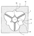
- FIG. 1 shows a cross-sectional view in the balloon placement step of the first method for manufacturing a balloon catheter according to the embodiment of the present invention
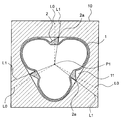
- FIG. 2 shows a cross-sectional view in the balloon contraction step.
- the first method for manufacturing a balloon catheter is a balloon having a shaft extending in the perspective direction and a balloon 1 provided on the distal side of the shaft and having a protrusion 2 on the outer surface.
- a method for manufacturing a catheter that is, a tubular object preparation step for preparing a tubular object 10 having a space portion 11 extending in the perspective direction inside, a balloon preparation step for preparing a balloon 1, and an inside of the tubular object 10.
- the distal side refers to the direction of the treatment subject with respect to the extending direction of the balloon 1
- the proximal side is used with respect to the opposite side of the distal side, that is, the extending direction of the balloon 1.
- the person that is, the direction of the operator's hand.
- the direction from the proximal side to the distal side of the balloon 1 is referred to as a perspective direction.
- the balloon catheter is configured so that fluid is supplied to the inside of the balloon 1 through a shaft, and the expansion and contraction of the balloon 1 can be controlled by using an indeflator (balloon pressurizer).
- the fluid may be a pressure fluid pressurized by a pump or the like.
- the shaft extends in the perspective direction, and a fluid flow path is provided inside. Further, it is preferable that the shaft has a guide wire insertion passage inside.
- the shaft has an outer tube and an inner tube, and the inner tube functions as a guide wire insertion passage. The space between the inner tube and the outer tube functions as a fluid flow path.
- the inner tube extends from the distal end of the outer tube and penetrates the balloon 1 in the perspective direction, the distal side of the balloon 1 is joined to the inner tube, and the balloon It is preferable that the proximal side of 1 is joined to the outer tube.
- the present invention is a so-called over-the-wire type balloon catheter in which a wire is inserted from the distal side to the proximal side of the shaft, and a so-called rapid exchange type in which the wire is inserted halfway from the distal side to the proximal side of the shaft. It can be applied to any of the balloon catheters of.
- the balloon catheter may have a hub on the proximal side of the shaft to deliver fluid to the shaft.
- the hub preferably has a fluid injection portion communicating with the fluid flow path supplied to the inside of the balloon 1 and a guide wire insertion portion communicating with the guide wire insertion passage.
- the balloon catheter has a hub having a fluid injection part and a guide wire insertion part, the operation of supplying fluid to the inside of the balloon 1 to expand and contract the balloon 1 and the balloon catheter along the guide wire can be operated.
- the operation of sending to the treatment target site becomes easy.
- the joining between the shaft and the hub includes, for example, adhesion with an adhesive, welding, and the like. Above all, it is preferable that the shaft and the hub are joined by adhesion.
- the shaft and the hub are made of a highly flexible material and the hub is made of a highly rigid material.
- the joint strength between the shaft and the hub can be increased. As a result, it becomes possible to increase the durability of the balloon catheter.
- the material constituting the shaft examples include polyamide-based resin, polyester-based resin, polyurethane-based resin, polyolefin-based resin, fluorine-based resin, vinyl chloride-based resin, silicone-based resin, and natural rubber. Only one of these may be used, or two or more thereof may be used in combination. Above all, the material constituting the shaft is preferably at least one of a polyamide resin, a polyolefin resin, and a fluorine resin. When the material constituting the shaft is at least one of a polyamide resin, a polyolefin resin, and a fluorine resin, the slipperiness of the surface of the shaft can be improved and the insertability of the balloon catheter into a blood vessel can be improved. ..
- Balloon 1 is provided on the distal side of the shaft.
- the joining between the balloon 1 and the shaft includes adhesion and welding with an adhesive, and caulking by attaching a ring-shaped member to a portion where the end of the balloon 1 and the shaft overlap.
- it is preferable that the balloon 1 and the shaft are joined by welding. Since the balloon 1 and the shaft are welded together, it becomes difficult to release the joint between the balloon 1 and the shaft even if the balloon 1 is repeatedly expanded and contracted. Therefore, the joint strength between the balloon 1 and the shaft can be easily increased.
- the balloon 1 preferably has a straight pipe portion, a proximal taper portion connected to the proximal side of the straight pipe portion, and a distal taper portion connected to the distal side of the straight pipe portion. It is preferable that the proximal taper portion and the distal taper portion are formed so as to reduce the diameter as the distance from the straight pipe portion increases. Since the balloon 1 has a straight tube portion, the straight tube portion is sufficiently in contact with the narrowed portion, and the narrowed portion can be easily expanded. Further, since the balloon 1 has a proximal taper portion and a distal taper portion whose outer diameter becomes smaller as the distance from the straight tube portion is increased, the balloon 1 is contracted and wound around the shaft. The outer diameters of the distal end and the proximal end of the balloon can be reduced to reduce the step between the shaft and the balloon 1. Therefore, it becomes easy to insert the balloon 1 in the perspective direction. In the present invention, the inflatable portion is regarded as the balloon 1.
- the material constituting the balloon 1 is, for example, a polyolefin resin such as polyethylene, polypropylene or an ethylene-propylene copolymer, a polyester resin such as polyethylene terephthalate or a polyester elastomer, a polyurethane resin such as polyurethane or a polyurethane elastomer, or a polyphenylene sulfide type.
- a polyolefin resin such as polyethylene, polypropylene or an ethylene-propylene copolymer
- a polyester resin such as polyethylene terephthalate or a polyester elastomer
- a polyurethane resin such as polyurethane or a polyurethane elastomer
- a polyphenylene sulfide type examples thereof include polyamide resins such as resins, polyamide elastomers, nylon 6, nylon 6/6, nylon 6/10 and nylon 12, and natural rubbers such as fluororesins, silicone resins and latex rubbers.
- the outer diameter of the balloon 1 is preferably 0.5 mm or more, more preferably 1 mm or more, and further preferably 1.5 mm or more.
- the outer diameter of the balloon 1 is preferably 35 mm or less, more preferably 30 mm or less, and even more preferably 25 mm or less.
- the length of the balloon 1 in the perspective direction is preferably 5 mm or more, more preferably 10 mm or more, and further preferably 15 mm or more.
- the length of the balloon 1 in the perspective direction is preferably 300 mm or less, more preferably 200 mm or less, and further preferably 100 mm or less.
- the thickness of the balloon 1 is preferably 5 ⁇ m or more, more preferably 7 ⁇ m or more, and further preferably 10 ⁇ m or more.
- the upper limit of the thickness of the balloon 1 can be set according to the application of the balloon catheter, and can be, for example, 100 ⁇ m or less, 90 ⁇ m or less, and 80 ⁇ m or less.
- the balloon 1 is provided with a protruding portion 2 on the outer surface. Since the balloon 1 has a protrusion 2 on the outer surface, a crack can be formed in a lesion where the protrusion 2 is calcified and hardened, and even if the lesion is a calcified lesion, the balloon 1 is sufficiently lesioned. Can be extended. Further, by expanding the balloon 1 in the ISR lesion, the protrusion 2 is likely to be caught in the new intima, which is soft and the surface is slippery, and the position of the balloon 1 is less likely to shift when the ISR lesion is expanded.
- the number of protrusions 2 may be one, but it is preferably plural. That is, it is preferable that a plurality of projecting portions 2 are provided on the outer surface of the balloon 1. When the number of the protrusions 2 is plurality, it becomes easy to crack the lesion portion hardened by calcification. In addition, the position of the balloon 1 can be made less likely to shift with respect to the ISR lesion.
- the protrusion 2 extends in the perspective direction.
- the perspective length of the protrusion 2 is preferably shorter than the perspective length of the balloon 1. Since the length of the protrusion 2 in the perspective direction is shorter than the length of the balloon 1 in the perspective direction, there is a portion where the protrusion 2 is not provided in a part of the balloon 1 in the perspective direction, and the balloon 1 is easily bent. .. Therefore, it is possible to improve the insertability of the balloon catheter in a curved blood vessel or the like.
- the material constituting the protrusion 2 is, for example, a polyolefin resin such as polyvinyl chloride, polyethylene, polypropylene or cyclic polyolefin, a polystyrene resin, a polymethylpentene resin such as poly- (4-methylpentene-1), or a polycarbonate.
- a polyolefin resin such as polyvinyl chloride, polyethylene, polypropylene or cyclic polyolefin
- a polystyrene resin a polymethylpentene resin such as poly- (4-methylpentene-1
- a polycarbonate Based resin, acrylic resin, ABS resin, polyethylene terephthalate, polyester resin such as polyethylene naphthalate, butadiene-styrene copolymer, polyamide elastomer, nylon 6, nylon 6.6, nylon 6/10, nylon 12, etc.
- the protruding portion 2 may be provided on the outer surface of the balloon 1 by integral molding with the same material as the material constituting the balloon 1, and the material different from the material constituting the balloon 1 may be provided with the balloon 1. May be separately formed and provided on the outer surface of the balloon 1.
- a tubular object 10 having a space portion 11 extending in the perspective direction is prepared.
- the balloon 1 can be arranged in the space portion 11 that the tubular object 10 has inside.
- the material constituting the tubular object 10 examples include synthetic resins such as polycarbonate resin, polyacetal resin and fluororesin, and metals such as iron, copper and stainless steel. Above all, the material constituting the tubular object 10 is preferably metal. Since the material constituting the tubular object 10 is metal, the strength of the tubular object 10 is increased, and the pressure applied to the inside of the balloon 1 in the balloon arranging step can be increased.
- the balloon preparation process prepare the balloon 1. After that, as shown in FIG. 1, in the balloon arranging step, the balloon 1 is arranged in the tubular object 10, and the inside of the balloon 1 is pressurized to inflate the balloon 1.
- Examples of the method of pressurizing the inside of the balloon 1 include supplying a fluid such as a gas such as air or nitrogen gas or a liquid such as pure water or physiological saline to the inside of the balloon 1.
- a fluid such as a gas such as air or nitrogen gas or a liquid such as pure water or physiological saline
- a pump or the like can be used.
- the balloon arranging step when the inside of the balloon 1 is pressurized in the tubular object 10 to inflate the balloon 1, at least a part of the outer surface of the balloon 1 is in contact with the inner surface of the space portion 11. Is preferable. In the balloon arranging step, at least a part of the outer surface of the balloon 1 is in contact with the inner surface of the space portion 11, so that the blade-shaped portion 3 can be easily formed in the balloon contraction step performed after the balloon arranging step.
- the center of gravity P1 of the tubular object 10 is centered on the center of gravity P1 of the tubular object 10 in a cross section perpendicular to the perspective direction of the tubular object 10.
- the protrusion 2 is arranged inside the circle C1.
- a balloon contraction step is performed in which the inside of the balloon 1 is depressurized and the balloon 1 is contracted to form the blade-shaped portion 3.
- the blade-shaped portion 3 refers to a portion where at least a part of the inner surface of the balloon 1 is in contact with each other in a state where the balloon 1 is contracted.
- the protruding portion 2 of the balloon 1 in the balloon arranging step, by arranging the protruding portion 2 of the balloon 1 inside the average circle C1, the protruding portion 2 can be arranged at a position close to the center of gravity P1 of the tubular object 10.
- the protruding portion 2 located closer to the center of gravity P1 of the tubular object 10 becomes the center of gravity P1 of the tubular object 10 rather than the protruding portion 2.
- the portion of the balloon 1 that reaches the center of gravity P1 of the tubular object 10 before the portion of the balloon 1 arranged at a distant position and does not reach the center of gravity P1 of the tubular object 10 at this point is the blade-shaped portion 3. It becomes.
- the protruding portion 2 can be arranged between the plurality of blade-shaped portions 3, and the balloon 1 can be folded while controlling the position of the protruding portion 2. Further, since the protruding portion 2 is arranged between the plurality of blade-shaped portions 3, it also has an effect that the protruding portion 2 is not easily crushed when the blade-shaped portion 3 is wound and folded.
- the time for depressurizing the inside of the balloon 1 in the balloon contraction step is preferably shorter than the time for pressurizing the inside of the balloon 1 in the balloon placement step.
- the balloon 1 in the balloon placement step can be gradually inflated, and the protruding portion 2 can be formed. It is possible to prevent the tubular object 10 from colliding with the inner surface and being deformed or the like.
- the number of blade-shaped portions 3 formed in the balloon contraction step may be one, but is preferably plural. Since the number of the blade-shaped portions 3 formed in the balloon contraction step is a plurality, the length of the blade-shaped portions 3 is less likely to be excessively long. Therefore, the balloon 1 can be easily folded neatly.
- FIG. 3 shows a cross-sectional view of the first balloon catheter manufacturing method in another embodiment of the present invention in the top pressing step.
- the inner side surface of the tubular object 10 and the top portion 2a of the protruding portion 2 are in contact with each other.
- the balloon 1 is inflated, or a protrusion-shaped portion capable of projecting from the outside to the inside of the tubular object 10 is provided on the inner surface of the tubular object 10 so that the protrusion-shaped portion is formed on the top portion 2a of the protrusion 2.
- the protrusion-shaped portion is moved inward of the tubular object 10 in contact with the tubular object 10, and a discharge port for a fluid such as air is provided at a portion of the tubular object 10 where the top portion 2a of the protrusion 2 is located.
- a discharge port for a fluid such as air
- compressed air or the like is discharged from the discharge port toward the top 2a of the protrusion 2.
- the top pressing step is preferably performed after the balloon placement step and before the balloon contraction step.
- FIG. 4 shows a cross-sectional view in the top pressing step of the first method for manufacturing a balloon catheter according to still another embodiment of the present invention.
- the balloon 1 has a plurality of projecting portions 2, and in the top pressing step, the inflated balloon 1 is rotated in one direction to be perpendicular to the perspective direction of the tubular object 10.
- the straight line L1 passing through the center of gravity P1 of the tubular object 10 and the top portion 2a of the protruding portion 2 in a cross section is circular with respect to the axial direction of the tubular object 10 and is of all the tubular objects 10.
- the circumferential direction of the straight line L1 passing through the center of gravity P1 and the top portion 2a of the protruding portion 2 is the same.
- the fact that the straight line L1 passing through the center of gravity P1 of the tubular object 10 and the top portion 2a of the protruding portion 2 "circulates" with respect to the axial direction of the tubular object 10 means that the tubular object 10 "circulates".
- the straight line L1 passing through the center of gravity P1 and the top 2a of the protrusion 2 is displaced in the circumferential direction about the axis of the cylinder 10 as it goes from the center of gravity P1 of the tubular object 10 toward the top 2a of the protrusion 2. It represents the state of being.
- a straight line L1 passing through the center of gravity P1 of the tubular object 10 and the top portion 2a of the protruding portion 2 is centered on an axis along the perspective direction of the tubular object 10, and the balloon 1 is formed. It shows a state of being displaced in the circumferential direction with respect to a straight line L0 passing through the center of gravity P1 of the tubular object 10 and the top portion 2a of the protruding portion 2 before being rotated in one direction.
- a straight line L1 passing through the center of gravity P1 of the tubular object 10 and the top portion 2a of the protruding portion 2 in a cross section perpendicular to the perspective direction of the tubular object 10 circulates in the axial direction of the tubular object 10 and Since the circumferential direction of the straight line L1 passing through the center of gravity P1 of all the tubular objects 10 and the top portion 2a of the projecting portion 2 is the same, the tubular object 10 is in a state where the projecting portion 2 is tilted in the circumferential direction of the balloon 1. It becomes easier to approach the center of gravity P1 of.
- the outer diameter of the balloon 1 folded in a state where the protruding portion 2 is tilted tends to be small, and the minimal invasiveness of the balloon catheter can be enhanced. Further, when the balloon 1 is expanded when the balloon catheter is used because the protruding portion 2 is tilted, the protruding portion 2 comes into contact with the lesion in a tilted state, and an oblique or spiral notch is made in the lesion. It is possible to increase the diastolic force of the balloon catheter. Further, when the balloon 1 is folded with the protruding portion 2 tilted, the top portion 2a of the protruding portion 2 is less likely to come into contact with the membrane portion of the balloon 1, and the balloon 1 can be less likely to be damaged.
- the tubular object 10 has a plurality of grooves 20 extending in the perspective direction inside, and the width W1 of the grooves 20 is the protrusion 2
- the width D1 of the groove 20 is larger than the width W2 and the depth d1 of the groove 20 is smaller than the height H1 of the protrusion 2.
- the protrusion placement step of arranging the protrusion 2 inside the groove 20 is performed. It is preferable that the groove portion 20 is located inside the average circle C1.
- the tubular object 10 has a plurality of groove portions 20 having a width W1 of the groove portion 20 larger than the width W2 of the protrusion portion 2 and a depth d1 of the groove portion 20 smaller than the height H1 of the protrusion portion 2 inside.
- the top portion 2a of the protruding portion 2 comes into contact with the inner side surface of the groove portion 20 to easily apply a force to the top portion 2a of the protruding portion 2.
- the protrusion 2 is rotated.
- the balloon 1 is arranged in the groove portion 20 in a tilted state, and the balloon 1 can be easily folded in a tilted state of the protruding portion 2.
- the protruding portion 2 arranged near the center of gravity P1 of the tubular object 10 when the inside of the balloon 1 is depressurized in the balloon contraction step is a balloon.
- the portion of the balloon 1 that reaches the center of gravity P1 of the tubular object 10 before the other portion of 1 and does not reach the center of gravity P1 of the tubular object 10 becomes the blade-shaped portion 3. Therefore, in the balloon 1 in the contracted state, the protruding portion 2 can be arranged between the plurality of blade-shaped portions 3, and the balloon 1 can be folded while controlling the position of the protruding portion 2.
- the balloon has good insertability into a lumen in the living body such as a blood vessel. It can be a catheter.
- the width W1 of the groove 20 is preferably larger than the width W2 of the protrusion 2, and the depth d1 of the groove 20 is preferably smaller than the height H1 of the protrusion 2.
- the width W1 of the groove portion 20 is preferably 1.1 times or more, more preferably 1.3 times or more, and further preferably 1.5 times or more the width W2 of the protruding portion 2.
- the depth d1 of the groove portion 20 is preferably 0.95 times or less, more preferably 0.9 times or less, and 0.85 times or less the height H1 of the protruding portion 2. More preferred.
- the protrusion In the portion arranging step By setting the lower limit of the ratio of the width W1 of the groove 20 and the width W2 of the protrusion 2 and the upper limit of the ratio of the width W1 of the groove 20 and the width W2 of the protrusion 2 to the above ranges, respectively, the protrusion In the portion arranging step, the top portion 2a of the protruding portion 2 easily comes into contact with the inside of the groove portion 20, and the efficiency of the top pressing step can be improved.
- the upper limit of the ratio between the width W1 of the groove 20 and the width W2 of the protrusion 2 is not particularly limited, but can be, for example, 10 times or less, 7 times or less, 5 times or less.
- the lower limit of the width W1 of the groove 20 and the width W2 of the protrusion 2 is not particularly limited, and can be, for example, 0.5 times or more, 0.6 times or more, and 0.7 times or more.
- FIG. 5 shows a cross-sectional view in the step of pressing both sides of the protruding portion of the first method for manufacturing a balloon catheter according to another embodiment of the present invention.
- a step of pressing both sides of the protrusion 2 inward of the tubular object 10 in a cross section perpendicular to the perspective direction after the balloon placement step To push both sides of the projecting portion 2 inward of the tubular object 10, for example, as shown in FIG. 5, the tubular object 10 is projected from the outside to the inside of the tubular object 10.
- a plurality of recessable protrusion-shaped portions 12 are provided, and the protrusion-shaped portions 12 can be moved inward of the tubular object 10 in a state where the two protrusion-shaped portions 12 are in contact with both side portions of the protrusions 2, respectively.
- Discharge ports for fluids such as air are provided in the portions of the tubular object 10 where both side portions of the projecting portion 2 are located, and compressed air or the like is discharged from the two discharge ports toward both side portions of the projecting portion 2. That can be mentioned.
- the protruding portion 2 By pushing both side portions of the protruding portion 2 inward of the tubular object 10, the protruding portion 2 is less likely to tilt in the circumferential direction of the balloon 1 in a cross section perpendicular to the perspective direction of the balloon 1, and the protruding portion 2 stands up. This makes it easier to approach the center of gravity P1 of the tubular object 10.
- the protrusion 2 hits the lesion vertically, and the internal pressure of the balloon 1 is efficiently transmitted to the lesion, resulting in high expansion. It becomes possible to exert power.
- the tubular object 10 has a plurality of groove portions 20 extending in the perspective direction inside, and the width W1 of the groove portion 20 is smaller than the width W2 of the protrusion 2 and the groove portion.
- the depth d1 of 20 is larger than the height H1 of the protrusion 2, and has a protrusion placement step of arranging the protrusion 2 inside the groove 20 after the balloon placement step, and the groove 20 is averaged. It is preferably located inside the circle C1.
- the tubular object 10 has a plurality of groove portions 20 having a width W1 of the groove portion 20 smaller than the width W2 of the protrusion portion 2 and a depth d1 of the groove portion 20 larger than the height H1 of the protrusion portion 2 inside.
- both side portions of the protruding portion 2 come into contact with the groove portion 20 to easily press both side portions of the protruding portion 2. Therefore, the balloon 1 can be folded in a state where the top portion 2a of the protruding portion 2 is not easily crushed.
- the protruding portion 2 arranged near the center of gravity P1 of the tubular object 10 when the inside of the balloon 1 is depressurized in the balloon contraction step is a balloon.
- the portion of the balloon 1 that reaches the center of gravity P1 of the tubular object 10 before the other portion of 1 and does not reach the center of gravity P1 of the tubular object 10 becomes the blade-shaped portion 3. Therefore, in the balloon 1 in the contracted state, the protruding portion 2 can be arranged between the plurality of blade-shaped portions 3, and the balloon 1 can be folded while controlling the position of the protruding portion 2. Further, since the protruding portion 2 is arranged between the plurality of blade-shaped portions 3 and the blade-shaped portion 3 is folded so as to cover the protruding portion 2, the protruding portion 2 is less likely to be crushed.
- the width W1 of the groove 20 is preferably smaller than the width W2 of the protrusion 2, and the depth d1 of the groove 20 is preferably larger than the height H1 of the protrusion 2.
- the width W1 of the groove portion 20 is preferably 0.95 times or less, more preferably 0.9 times or less, and further preferably 0.85 times or less the width W2 of the protruding portion 2.
- the depth d1 of the groove portion 20 is preferably 1.1 times or more, more preferably 1.3 times or more, and 1.5 times or more the height H1 of the protruding portion 2. More preferred.
- the protrusions are formed.
- both side portions of the protruding portion 2 are likely to come into contact with the groove portion 20, and the step of pressing both side portions of the protruding portion can be efficiently performed.
- the lower limit of the ratio of the width W1 of the groove portion 20 to the width W2 of the protruding portion 2 is not particularly limited, and can be, for example, 0.5 times or more, 0.6 times or more, 0.7 times or more.
- the upper limit of the ratio of the width W1 of the groove portion 20 to the width W2 of the protrusion 2 is not particularly limited, but can be, for example, 10 times or less, 7 times or less, 5 times or less.
- the width W1 of the groove 20 may be larger than the width W2 of the protrusion 2, and the depth d1 of the groove 20 may be larger than the height H1 of the protrusion 2. Since the width W1 of the groove 20 is larger than the width W2 of the protrusion 2 and the depth d1 of the groove 20 is larger than the height H1 of the protrusion 2, it is easy to arrange the protrusion 2 inside the groove 20. Become.
- FIG. 6 shows a cross-sectional view in the balloon placement step of the second method for manufacturing a balloon catheter according to the embodiment of the present invention
- FIG. 7 shows a cross-sectional view in the balloon contraction step.
- a second method for manufacturing a balloon catheter is a balloon having a shaft extending in the perspective direction and a balloon 1 provided on the distal side of the shaft and having a protrusion 2 on the outer surface.
- a method for manufacturing a catheter wherein a tubular object preparation step of preparing a tubular object 10 having a space portion 11 extending in the perspective direction and a plurality of groove portions 20 extending in the perspective direction inside, and a balloon 1 are performed.
- a balloon preparation step to prepare a balloon placement step of arranging the balloon 1 in the tubular object 10 and pressurizing the inside of the balloon 1 to inflate the balloon 1, and depressurizing the inside of the balloon 1 to contract the balloon 1. It has a balloon contraction step of forming the blade-shaped portion 3.
- a tubular object 10 having a space portion 11 extending in the perspective direction and a plurality of groove portions 20 extending in the perspective direction is prepared.
- a balloon arrangement step is performed in which the balloon 1 is arranged in the tubular object 10 and the inside of the balloon 1 is pressurized to inflate the balloon 1.
- the center of gravity P1 of the tubular object 10 is centered on the center of gravity P1 of the tubular object 10 in the cross section perpendicular to the perspective direction of the tubular object 10.
- the protrusion 2 is arranged inside the circle C1.
- the protrusion 2 is arranged inside the groove 20.
- the protrusion 2 is arranged inside the groove 20.
- the protrusion 2 is inserted into the groove 20 by pressurizing the inside of the balloon 1.
- a balloon contraction step is performed in which the inside of the balloon 1 is depressurized and the balloon 1 is contracted to form the blade-shaped portion 3.
- the difference between the width W1 of the groove 20 and the width W2 of the protrusion 2 is 50% or less (0%) of the width W2 of the protrusion 2. Includes). Since the difference between the width W1 of the groove 20 and the width W2 of the protrusion 2 is 50% or less (including 0%) of the width W2 of the protrusion 2, the protrusion 2 is held by the groove 20 with a certain force. , It becomes possible to control the position of the protruding portion 2 in the balloon contraction step.
- the difference between the width W1 of the groove 20 and the width W2 of the protrusion 2 is 0% of the width W2 of the protrusion 2, which means that the width W1 of the groove 20 and the width W2 of the protrusion 2 are the same. Is shown.
- the inside of the balloon 1 is depressurized in the balloon contraction step.
- the portion of the balloon 1 that is not held by the tubular object 10 contracts to start forming the blade-shaped portion 3, and as the pressure inside the balloon 1 decreases, the protruding portion 2 is pulled toward the inside of the balloon 1. 2 becomes larger, and when the force for pulling the balloon 1 inward is higher than the force for holding the protrusion 2, the protrusion 2 comes off from the groove 20, so that the balloon is controlled while controlling the position of the protrusion 2. 1 can be folded.
- the difference between the width W1 of the groove 20 and the width W2 of the protrusion 2 is preferably 50% or less, preferably 45% or less of the width W2 of the protrusion 2. More preferably, it is more preferably 40% or less.
- the difference between the width W1 of the groove 20 and the width W2 of the protrusion 2 is preferably 3% or more, more preferably 5% or more, and 10% or more of the width W2 of the protrusion 2. Is even more preferable.
- the width W1 of the groove portion 20 may be larger than the width W2 of the protruding portion 2, but may be smaller.
- the width W1 of the groove 20 is smaller than the width W2 of the protrusion 2
- the entire protrusion 2 does not fit inside the groove 20 and is in the middle of the protrusion 2. Is sandwiched between the groove portions 20, the groove portion 20 can hold the protrusion portion 2, and the position of the protrusion portion 2 can be controlled when the balloon 1 is folded.
- the groove portion 20 is preferably located inside the average circle C1. Since the groove 20 is located inside the average circle C1, it becomes easy to control the position of the protrusion 2 in the balloon contraction step.
- the number of the protruding portions 2 is a plurality and the number of the groove portions 20 is equal to the number of the protruding portions 2. Since the number of protrusions 2 and the number of grooves 20 are both a plurality and the same number, it is possible to manufacture a balloon catheter having a protrusion 2 capable of sufficiently dilating a narrowed portion of a calcified lesion or an ISR lesion. it can. Further, it is possible to prevent the protruding portion 2 from being crushed by being pressed against the inner surface of the tubular object 10 during the manufacture of the balloon catheter.
- the protruding portion 2 is made of the same material as the main body of the balloon 1. Since the protruding portion 2 is made of the same material as the balloon 1 main body, it is possible to increase the joint strength between the balloon 1 main body and the protruding portion 2.
- the balloon 1 main body and the protruding portion 2 are integrally molded products. Since the balloon 1 main body and the protruding portion 2 are integrally molded products, the bonding force between the balloon 1 main body and the protruding portion 2 can be further increased. Further, since the step of joining the protruding portion 2 to the balloon 1 main body is not required, the time required for forming the balloon 1 can be shortened and the manufacturing efficiency can be improved.
- the balloon 1 has a hydrophilic coating on the outer surface and has a coating removing step of removing the hydrophilic coating on the top 2a of the protruding portion 2.
- a hydrophilic coating to the outer surface of the balloon 1 and removing the hydrophilic coating on the top 2a of the protrusion 2
- the top 2a of the protrusion 2 has low slipperiness, so that the protrusion 2 is easily caught on the lesion.
- the outer surface of the balloon 1 excluding the top portion 2a of the protruding portion 2 is highly slippery due to the hydrophilic coating, it is possible to obtain a balloon catheter that is easy to perform the procedure.
- the coating removing step is performed after the balloon arranging step, and in the coating removing step, it is preferable that the balloon 1 is slid in the perspective direction so that the outer surface of the protruding portion 2 and the inner surface of the tubular object 10 are brought into contact with each other. .. That is, it is preferable to remove the hydrophilic coating on the outer surface of the protruding portion 2 by sliding the hydrophilic coating applied to the outer surface of the protruding portion 2 while contacting the inner surface of the tubular object 10. ..
- the coating removing step is performed by sliding the balloon 1 in the perspective direction and bringing the outer surface of the protrusion 2 into contact with the inner surface of the tubular object 10, so that the balloon 1 remains arranged in the tubular object 10. ,
- the coating removal process can be performed with a simple operation. Therefore, it is possible to improve the manufacturing efficiency of the balloon catheter.
- the tubular object 10 has a groove portion 20 extending in the perspective direction, a protrusion 2 is arranged inside the groove portion 20, and the balloon 1 is slid in the perspective direction in the coating removing step to slide the protrusion 2 in the perspective direction. It is preferable that the outer surface of the groove 20 is brought into contact with the inner surface of the groove 20. By performing the coating removing step by bringing the outer surface of the protrusion 2 into contact with the inner surface of the groove 20, the entire protrusion 2 can easily come into contact with the inner surface of the groove 20. Therefore, the hydrophilic coating provided on the outer surface of the protrusion 2 can be efficiently removed.
- the portion in contact with the outer surface of the protruding portion 2 preferably has a higher surface average roughness Rz than the other portions.
- the surface average roughness Rz of the portion in contact with the outer surface of the protruding portion 2 is higher than the surface average roughness Rz of the other portion, so that the outer surface of the protruding portion 2 While the hydrophilic coating can be removed efficiently, the hydrophilic coating on the outer surface of the balloon 1 excluding the protrusion 2 is difficult to remove. As a result, it is possible to facilitate the manufacture of a balloon catheter in which the slipperiness of the surface of only the protruding portion 2 is reduced.
- the first method for manufacturing a balloon catheter includes a shaft extending in the perspective direction, a balloon provided on the distal side of the shaft and having a protrusion on the outer surface.
- a method for manufacturing a balloon catheter having a balloon catheter which includes a tubular object preparation step for preparing a tubular object having a space extending in the perspective direction inside, a balloon preparation step for preparing a balloon, and a inside the tubular object. It has a balloon placement step of arranging a balloon and pressurizing the inside of the balloon to inflate the balloon, and a balloon contraction step of depressurizing the inside of the balloon and contracting the balloon to form a wing-shaped portion.
- a second method for manufacturing a balloon catheter is a balloon having a shaft extending in the perspective direction and a balloon provided on the distal side of the shaft and having a protrusion on the outer surface.
- a method for manufacturing a catheter which is a tubular object preparation step for preparing a tubular object having a space portion extending in the perspective direction and a plurality of grooves extending in the perspective direction inside, and a balloon preparation for preparing a balloon.
- a step a balloon placement step of arranging a balloon in a tubular object and pressurizing the inside of the balloon to inflate the balloon, and a balloon contraction step of depressurizing the inside of the balloon and contracting the balloon to form a wing-shaped portion.
- the balloon placement process from the center of gravity of the tubular object to the inner surface of the tubular object, centered on the center of gravity of the tubular object, in a cross section perpendicular to the perspective direction of the tubular object.
- a balloon is placed inside an average circle whose radius is the average of the distance of the shortest distance and the distance of the longest distance from the center of gravity of the tubular object to the inner surface of the tubular object.
- a protruding portion is arranged inside the groove portion.
- Balloon 2 Protruding part 2a: Top of protruding part 3: Blade-shaped part 10: Cylindrical object 11: Space part 20: Groove part P1: Center of gravity of tubular object P2: From the center of gravity of the tubular object to the inside of the tubular object The part with the shortest distance to the side surface P3: The part with the longest distance from the center of gravity of the tubular object to the inner surface of the tubular object D1: The part with the shortest distance from the center of gravity of the tubular object to the inner surface of the tubular object Distance D2: Distance from the center of gravity of the tubular object to the inner surface of the tubular object with the longest distance C1: Distance from the center of gravity of the tubular object to the inner surface of the tubular object with the shortest distance An average circle whose radius is the average value of the distances from the center of gravity of the tubular object to the inner surface of the tubular object L0: The center of gravity of the tubular object and the protruding portion before the balloon
Landscapes
- Health & Medical Sciences (AREA)
- Engineering & Computer Science (AREA)
- Life Sciences & Earth Sciences (AREA)
- Heart & Thoracic Surgery (AREA)
- Manufacturing & Machinery (AREA)
- Anesthesiology (AREA)
- Biophysics (AREA)
- Pulmonology (AREA)
- Child & Adolescent Psychology (AREA)
- Biomedical Technology (AREA)
- Hematology (AREA)
- Animal Behavior & Ethology (AREA)
- General Health & Medical Sciences (AREA)
- Public Health (AREA)
- Veterinary Medicine (AREA)
- Mechanical Engineering (AREA)
- Media Introduction/Drainage Providing Device (AREA)
Abstract
Une méthode de production d'un cathéter à ballonnet comprend : une étape de préparation d'objet cylindrique consistant à préparer un objet cylindrique (10) ayant une partie spatiale (11) s'étendant dans une direction loin-proche à l'intérieur de celui-ci ; une étape de préparation de ballonnet consistant à préparer un ballonnet (1) ; une étape d'agencement de ballonnet consistant à agencer le ballonnet (1) dans l'objet cylindrique (10) et mettre sous pression l'intérieur du ballonnet (1) pour dilater le ballonnet (1) ; et une étape de contraction de ballonnet consistant à dépressuriser l'intérieur du ballonnet (1) et contracter le ballonnet (1) pour former une partie de forme de lame (3). Dans l'étape d'agencement de ballonnet, une partie en saillie (2) est disposée à l'intérieur d'un cercle moyen C1 dont le rayon est une valeur moyenne d'une distance D1 d'une partie P2 dans laquelle une distance d'un point de gravité P1 de l'objet cylindrique (10) à une surface interne de l'objet cylindrique (10) est la plus courte et d'une distance D2 d'une partie P3 dans laquelle une distance du point de gravité P1 de l'objet cylindrique (10) à la surface interne de l'objet cylindrique (10) est la plus longue autour du point de gravité P1 de l'objet cylindrique (10) dans une section transversale orthogonale à la direction loin-proche de l'objet cylindrique (10).
Priority Applications (2)
| Application Number | Priority Date | Filing Date | Title |
|---|---|---|---|
| JP2021545195A JP7490660B2 (ja) | 2019-09-09 | 2020-08-24 | バルーンカテーテルの製造方法 |
| US17/640,882 US20220323728A1 (en) | 2019-09-09 | 2020-08-24 | Method for producing balloon catheter |
Applications Claiming Priority (2)
| Application Number | Priority Date | Filing Date | Title |
|---|---|---|---|
| JP2019-163858 | 2019-09-09 | ||
| JP2019163858 | 2019-09-09 |
Publications (1)
| Publication Number | Publication Date |
|---|---|
| WO2021049282A1 true WO2021049282A1 (fr) | 2021-03-18 |
Family
ID=74866507
Family Applications (1)
| Application Number | Title | Priority Date | Filing Date |
|---|---|---|---|
| PCT/JP2020/031828 WO2021049282A1 (fr) | 2019-09-09 | 2020-08-24 | Méthode de production de cathéter à ballonnet |
Country Status (3)
| Country | Link |
|---|---|
| US (1) | US20220323728A1 (fr) |
| JP (1) | JP7490660B2 (fr) |
| WO (1) | WO2021049282A1 (fr) |
Cited By (6)
| Publication number | Priority date | Publication date | Assignee | Title |
|---|---|---|---|---|
| WO2023079906A1 (fr) * | 2021-11-08 | 2023-05-11 | 株式会社カネカ | Ballonnet pour cathéter à ballonnet |
| WO2023080063A1 (fr) * | 2021-11-08 | 2023-05-11 | 株式会社カネカ | Ballonnet pour cathéter à ballonnet |
| WO2023085112A1 (fr) * | 2021-11-09 | 2023-05-19 | 株式会社カネカ | Cathéter à ballonnet |
| WO2024029272A1 (fr) * | 2022-08-02 | 2024-02-08 | 株式会社カネカ | Ballonnet de cathéter à ballonnet, cathéter à ballonnet équipé de celui-ci, et procédé de fabrication de cathéter à ballonnet |
| WO2024106083A1 (fr) * | 2022-11-16 | 2024-05-23 | 株式会社カネカ | Ballonnet pour cathéter à ballonnet, et cathéter à ballonnet |
| WO2024106084A1 (fr) * | 2022-11-16 | 2024-05-23 | 株式会社カネカ | Ballonnet pour cathéter à ballonnet et cathéter à ballonnet |
Citations (4)
| Publication number | Priority date | Publication date | Assignee | Title |
|---|---|---|---|---|
| JPH05293174A (ja) * | 1992-04-17 | 1993-11-09 | Interventional Technol Inc | 折りたたみ式バルーンカテーテルを作る方法 |
| US20010047149A1 (en) * | 1998-03-04 | 2001-11-29 | Scimed Life Systems, Inc. | Balloon wrap device and method |
| US20060091585A1 (en) * | 2004-10-29 | 2006-05-04 | Kelley Greg S | Medical balloon folding method and tooling |
| JP2014140462A (ja) * | 2013-01-23 | 2014-08-07 | Sumitomo Bakelite Co Ltd | バルーン収縮用補助具、カテーテルセットおよびバルーン収縮方法 |
Family Cites Families (3)
| Publication number | Priority date | Publication date | Assignee | Title |
|---|---|---|---|---|
| US7972351B2 (en) | 2004-07-13 | 2011-07-05 | Boston Scientific Scimed, Inc. | Balloon folding design and method and apparatus for making balloons |
| US20070112300A1 (en) | 2005-11-14 | 2007-05-17 | Roman Ricardo D | Balloon folding design, apparatus and method of making the same |
| JP5293174B2 (ja) | 2008-12-26 | 2013-09-18 | 横河電機株式会社 | 機器管理システム及び機器管理プログラム |
-
2020
- 2020-08-24 WO PCT/JP2020/031828 patent/WO2021049282A1/fr active Application Filing
- 2020-08-24 US US17/640,882 patent/US20220323728A1/en active Pending
- 2020-08-24 JP JP2021545195A patent/JP7490660B2/ja active Active
Patent Citations (4)
| Publication number | Priority date | Publication date | Assignee | Title |
|---|---|---|---|---|
| JPH05293174A (ja) * | 1992-04-17 | 1993-11-09 | Interventional Technol Inc | 折りたたみ式バルーンカテーテルを作る方法 |
| US20010047149A1 (en) * | 1998-03-04 | 2001-11-29 | Scimed Life Systems, Inc. | Balloon wrap device and method |
| US20060091585A1 (en) * | 2004-10-29 | 2006-05-04 | Kelley Greg S | Medical balloon folding method and tooling |
| JP2014140462A (ja) * | 2013-01-23 | 2014-08-07 | Sumitomo Bakelite Co Ltd | バルーン収縮用補助具、カテーテルセットおよびバルーン収縮方法 |
Cited By (6)
| Publication number | Priority date | Publication date | Assignee | Title |
|---|---|---|---|---|
| WO2023079906A1 (fr) * | 2021-11-08 | 2023-05-11 | 株式会社カネカ | Ballonnet pour cathéter à ballonnet |
| WO2023080063A1 (fr) * | 2021-11-08 | 2023-05-11 | 株式会社カネカ | Ballonnet pour cathéter à ballonnet |
| WO2023085112A1 (fr) * | 2021-11-09 | 2023-05-19 | 株式会社カネカ | Cathéter à ballonnet |
| WO2024029272A1 (fr) * | 2022-08-02 | 2024-02-08 | 株式会社カネカ | Ballonnet de cathéter à ballonnet, cathéter à ballonnet équipé de celui-ci, et procédé de fabrication de cathéter à ballonnet |
| WO2024106083A1 (fr) * | 2022-11-16 | 2024-05-23 | 株式会社カネカ | Ballonnet pour cathéter à ballonnet, et cathéter à ballonnet |
| WO2024106084A1 (fr) * | 2022-11-16 | 2024-05-23 | 株式会社カネカ | Ballonnet pour cathéter à ballonnet et cathéter à ballonnet |
Also Published As
| Publication number | Publication date |
|---|---|
| JPWO2021049282A1 (fr) | 2021-03-18 |
| JP7490660B2 (ja) | 2024-05-27 |
| US20220323728A1 (en) | 2022-10-13 |
Similar Documents
| Publication | Publication Date | Title |
|---|---|---|
| WO2021049282A1 (fr) | Méthode de production de cathéter à ballonnet | |
| US20160206454A1 (en) | Stent Delivery Catheter With Balloon Control Bands | |
| US10251766B2 (en) | Balloon catheters and systems and methods for delivering stents using such catheters | |
| US20090171284A1 (en) | Dilation system | |
| WO2020195697A1 (fr) | Cathéter à ballonnet | |
| JP2017205555A (ja) | 拡張可能な医療装置 | |
| JP6706889B2 (ja) | バルーンカテーテル | |
| WO2006134638A1 (fr) | Cathéter à ballonnet | |
| WO2022102766A1 (fr) | Ballonnet pour cathéter à ballonnet | |
| JP5671859B2 (ja) | バルーンカテーテル | |
| WO2020195170A1 (fr) | Cathéter à ballonnet | |
| JP7432360B2 (ja) | バルーンカテーテルの製造方法および金型 | |
| WO2021049261A1 (fr) | Procédé de fabrication de cathéter à ballonnet | |
| JP7359853B2 (ja) | バルーンカテーテル | |
| JP2010029318A (ja) | バルーンカテーテル | |
| US10251765B2 (en) | Stent delivery system and manufacturing method for the same | |
| WO2013136636A1 (fr) | Cathéter à ballonnet et système de mise en place de stent | |
| JP7100666B2 (ja) | バルーンカテーテルおよびその製造方法 | |
| JP2022053075A (ja) | バルーンカテーテル | |
| JP2004298269A (ja) | カテーテルおよびその製造方法 | |
| WO2022196166A1 (fr) | Ballonnet pour cathéter à ballonnet | |
| WO2022102189A1 (fr) | Ballonnet pour cathéter à ballonnet | |
| WO2022137763A1 (fr) | Ballonnet pour cathéter à ballonnet | |
| US20210228838A1 (en) | System and method for controlled delivery of medical devices into patient bodies | |
| JP2022017978A (ja) | カテーテル |
Legal Events
| Date | Code | Title | Description |
|---|---|---|---|
| 121 | Ep: the epo has been informed by wipo that ep was designated in this application |
Ref document number: 20864023 Country of ref document: EP Kind code of ref document: A1 |
|
| ENP | Entry into the national phase |
Ref document number: 2021545195 Country of ref document: JP Kind code of ref document: A |
|
| NENP | Non-entry into the national phase |
Ref country code: DE |
|
| 122 | Ep: pct application non-entry in european phase |
Ref document number: 20864023 Country of ref document: EP Kind code of ref document: A1 |