WO2023149151A1 - 車輪用軸受装置 - Google Patents
車輪用軸受装置 Download PDFInfo
- Publication number
- WO2023149151A1 WO2023149151A1 PCT/JP2023/000033 JP2023000033W WO2023149151A1 WO 2023149151 A1 WO2023149151 A1 WO 2023149151A1 JP 2023000033 W JP2023000033 W JP 2023000033W WO 2023149151 A1 WO2023149151 A1 WO 2023149151A1
- Authority
- WO
- WIPO (PCT)
- Prior art keywords
- wheel
- bearing device
- hub
- mounting flange
- wheel bearing
- Prior art date
- Legal status (The legal status is an assumption and is not a legal conclusion. Google has not performed a legal analysis and makes no representation as to the accuracy of the status listed.)
- Ceased
Links
Images



Classifications
-
- B—PERFORMING OPERATIONS; TRANSPORTING
- B60—VEHICLES IN GENERAL
- B60B—VEHICLE WHEELS; CASTORS; AXLES FOR WHEELS OR CASTORS; INCREASING WHEEL ADHESION
- B60B35/00—Axle units; Parts thereof ; Arrangements for lubrication of axles
- B60B35/02—Dead axles, i.e. not transmitting torque
-
- F—MECHANICAL ENGINEERING; LIGHTING; HEATING; WEAPONS; BLASTING
- F16—ENGINEERING ELEMENTS AND UNITS; GENERAL MEASURES FOR PRODUCING AND MAINTAINING EFFECTIVE FUNCTIONING OF MACHINES OR INSTALLATIONS; THERMAL INSULATION IN GENERAL
- F16C—SHAFTS; FLEXIBLE SHAFTS; ELEMENTS OR CRANKSHAFT MECHANISMS; ROTARY BODIES OTHER THAN GEARING ELEMENTS; BEARINGS
- F16C19/00—Bearings with rolling contact, for exclusively rotary movement
- F16C19/02—Bearings with rolling contact, for exclusively rotary movement with bearing balls essentially of the same size in one or more circular rows
- F16C19/14—Bearings with rolling contact, for exclusively rotary movement with bearing balls essentially of the same size in one or more circular rows for both radial and axial load
- F16C19/18—Bearings with rolling contact, for exclusively rotary movement with bearing balls essentially of the same size in one or more circular rows for both radial and axial load with two or more rows of balls
-
- F—MECHANICAL ENGINEERING; LIGHTING; HEATING; WEAPONS; BLASTING
- F16—ENGINEERING ELEMENTS AND UNITS; GENERAL MEASURES FOR PRODUCING AND MAINTAINING EFFECTIVE FUNCTIONING OF MACHINES OR INSTALLATIONS; THERMAL INSULATION IN GENERAL
- F16C—SHAFTS; FLEXIBLE SHAFTS; ELEMENTS OR CRANKSHAFT MECHANISMS; ROTARY BODIES OTHER THAN GEARING ELEMENTS; BEARINGS
- F16C33/00—Parts of bearings; Special methods for making bearings or parts thereof
- F16C33/30—Parts of ball or roller bearings
- F16C33/58—Raceways; Race rings
-
- F—MECHANICAL ENGINEERING; LIGHTING; HEATING; WEAPONS; BLASTING
- F16—ENGINEERING ELEMENTS AND UNITS; GENERAL MEASURES FOR PRODUCING AND MAINTAINING EFFECTIVE FUNCTIONING OF MACHINES OR INSTALLATIONS; THERMAL INSULATION IN GENERAL
- F16C—SHAFTS; FLEXIBLE SHAFTS; ELEMENTS OR CRANKSHAFT MECHANISMS; ROTARY BODIES OTHER THAN GEARING ELEMENTS; BEARINGS
- F16C33/00—Parts of bearings; Special methods for making bearings or parts thereof
- F16C33/30—Parts of ball or roller bearings
- F16C33/58—Raceways; Race rings
- F16C33/64—Special methods of manufacture
-
- Y—GENERAL TAGGING OF NEW TECHNOLOGICAL DEVELOPMENTS; GENERAL TAGGING OF CROSS-SECTIONAL TECHNOLOGIES SPANNING OVER SEVERAL SECTIONS OF THE IPC; TECHNICAL SUBJECTS COVERED BY FORMER USPC CROSS-REFERENCE ART COLLECTIONS [XRACs] AND DIGESTS
- Y02—TECHNOLOGIES OR APPLICATIONS FOR MITIGATION OR ADAPTATION AGAINST CLIMATE CHANGE
- Y02T—CLIMATE CHANGE MITIGATION TECHNOLOGIES RELATED TO TRANSPORTATION
- Y02T10/00—Road transport of goods or passengers
- Y02T10/80—Technologies aiming to reduce greenhouse gasses emissions common to all road transportation technologies
- Y02T10/86—Optimisation of rolling resistance, e.g. weight reduction
Definitions
- the present invention relates to a wheel bearing device.
- a wheel bearing device that rotatably supports a wheel in a suspension system of an automobile or the like is known.
- a wheel pilot portion for guiding an inner diameter surface of a wheel is formed at an end portion of a hub wheel.
- the hub wheel is formed with a wheel pilot portion that extends toward the outboard side of the wheel mounting flange and guides the inner diameter surface of the wheel.
- the wheel bearing device has a problem that the pilot portion of the hub wheel, the wheel, and the brake rotor stick together due to dirt, rust, and the like due to the usage environment and aging.
- a tool is inserted between the pilot portion of the hub wheel, the wheel, and the brake rotor through a recess formed on the outer peripheral surface of the pilot portion to separate the stuck portion.
- the hub bolt and the tool will come into contact when the tool is inserted into the recess with the hub bolt installed, and the fixed part will be separated. It was sometimes difficult to make Also, if you try to forcibly separate the stuck wheel and brake rotor, the pilot part of the hub wheel will be damaged with a tool, etc., and interference during reassembly and dust generated from the scratched part will interfere with the installation of the wheel and brake rotor. It can get into the surface and lose the perpendicularity of the mounting. If the right angle of the wheels is lost, resistance occurs when the vehicle travels straight, which may lead to uneven wear of the tires.
- the present invention has been made in view of the circumstances described above. To provide a bearing device for a wheel capable of extending service life by preventing contamination and rust of a hub wheel.
- an outer member having a double-row outer raceway surface formed on its inner circumference;
- a hub wheel integrally having a wheel mounting flange on the outboard side and having an axially extending cylindrical small-diameter stepped portion formed on the outer periphery thereof; and at least one inner ring press-fitted into the small-diameter stepped portion of the hub wheel.
- a wheel bearing device comprising: a double-row rolling element rollably accommodated between both rolling surfaces,
- the hub wheel has a wheel pilot portion that extends to the outboard side from the wheel mounting flange and guides the inner diameter surface of the wheel, and a recess having a depth of 1 to 3 mm is formed on the outer peripheral surface of the wheel pilot portion.
- the tool while reducing the weight of the entire hub wheel, by making it easier to insert a tool between the pilot portion of the hub wheel, the wheel, and the brake rotor, the tool can be easily inserted between the hub wheel, the wheel, and the brake rotor. Separation becomes possible even if rust occurs and sticks.
- a wheel bearing device 1 shown in FIG. 1 is an embodiment of a wheel bearing device according to the present invention, and is for rotatably supporting a wheel in a suspension device of a vehicle such as an automobile.
- the wheel bearing device 1 has a configuration called a third generation, and includes an outer ring 2 as an outer member, a hub wheel 3 and an inner ring 4 as inner members, and two rows of inner rings as rolling trains.
- a side ball train 5 and an outer ball train 6, a magnetic encoder 11, and a sensor holder 12 are provided.
- the axial direction means the direction along the rotation axis X of the wheel bearing device 1.
- the inner side is one side in the axial direction and represents the vehicle body side of the wheel bearing device 1 when it is attached to the vehicle body
- the outer side is the other side in the axial direction when it is attached to the vehicle body. represents the wheel side of the wheel bearing device 1 of .
- An inner side opening 2a into which the sensor holder 12 can be fitted is formed at the inner side end of the outer ring 2, which is the outer member.
- An outer-side opening 2b into which an outer-side sealing member 9 can be fitted is formed in the outer-side end portion of the outer ring 2 .
- a sensor holder 12 is fitted into an inner side opening 2a which is an opening at one end in the axial direction of the annular space S formed by the outer ring 2 and the hub ring 3, and the opening at the other end in the axial direction of the annular space S is fitted.
- An inner raceway surface 2c on the inner side and an outer raceway surface 2d on the outer side are formed on the inner peripheral surface of the outer ring 2.
- a vehicle mounting flange 2e for mounting the outer ring 2 to a vehicle body member is integrally formed on the outer peripheral surface of the outer ring 2 .
- the vehicle body mounting flange 2e is provided with a bolt hole 2g into which a fastening member (here, a bolt) for fastening the vehicle body side member and the outer ring 2 is inserted.
- the outer ring 2 is located on the outer diameter side of the hub ring 3 and the inner ring 4 .
- a small-diameter stepped portion 3a whose diameter is smaller than that of the outer-side end portion is formed on the outer peripheral surface of the inner-side end portion of the hub wheel 3, which is the inner member.
- a wheel mounting flange 3b for mounting a wheel is integrally formed on the outer side end of the hub wheel 3. As shown in FIG.
- the wheel mounting flange 3b is formed with bolt holes 3f, which are a plurality of insertion holes.
- a hub bolt 3e is press-fitted into the bolt hole 3f for fastening the hub wheel 3 and the wheel or brake component.
- An outer-side inner raceway surface 3c is provided on the outer peripheral surface of the hub wheel 3 so as to face the outer-side outer raceway surface 2d of the outer ring 2 . That is, the inner raceway surface 3c is formed by the hub wheel 3 on the outer side of the inner member.
- a seal land portion 3 d of an outer side seal member 9 is formed on the base side of the wheel mounting flange 3 b of the hub wheel 3 .
- the outer-side sealing member 9 has a metal core 91 fitted to the outer-side opening 2 b of the outer ring 2 and a sealing member 92 integrally joined to the metal core 91 .
- the seal member 92 is in sliding contact with the seal land portion 3 d of the hub wheel 3 .
- An inner ring 4 is provided on the small-diameter stepped portion 3a of the hub ring 3.
- the inner ring 4 is fixed to the small-diameter stepped portion 3a of the hub wheel 3 by press-fitting and caulking.
- the inner ring 4 applies preload to the inner ball row 5 and the outer ball row 6 which are rolling rows.
- An inner raceway surface 4 a is provided on the outer peripheral surface of the inner ring 4 so as to face the inner raceway surface 2 c of the outer ring 2 . That is, the inner raceway surface 4a is formed by the inner ring 4 on the inner side of the inner member.
- the inner ring 4 which is an inner member, has an inner side end face 4b at the inner side end.
- the hub wheel 3 has an inner side end portion formed with a crimped portion 3h which is crimped to the inner side end face 4b of the inner ring 4. As shown in FIG.
- the inner ball row 5 and the outer ball row 6, which are rolling rows, are formed by holding a plurality of balls 7, which are rolling elements, by a retainer 8.
- the inner ball row 5 is rotatably sandwiched between the inner raceway surface 4a of the inner ring 4 and the outer raceway surface 2c of the outer ring 2 on the inner side.
- the outer-side ball row 6 is rollably sandwiched between the inner raceway surface 3c of the hub wheel 3 and the outer-side raceway surface 2d of the outer ring 2 . That is, the inner ball row 5 and the outer ball row 6 are housed so as to roll freely between the raceway surfaces of the outer member and the inner member.
- the outer ring 2 rotatably supports the hub wheel 3 and the inner ring 4 via the inner ball row 5 and the outer ball row 6 .
- an outer ring 2 as an outer member, a hub ring 3 and an inner ring 4 as inner members, an inner ball row 5, and an outer ball row 6 form a double-row angular contact ball bearing. It is configured. Note that the wheel bearing device 1 may constitute a double-row tapered roller bearing instead of the double-row angular contact ball bearing.
- the wheel pilot portion 3g is formed by extending from the outer end surface of the wheel mounting flange 3b of the hub wheel 3 to the outer side along the axial direction. This is the part that guides the inner diameter surface.
- the wheel pilot portion 3g preferably has a smooth inner surface to guide the inner diameter surface of the wheel or brake component. For example, if the inner surface of the wheel pilot portion 3g is damaged during assembly, dirt generated from the damaged portion may enter the inner diameter surface of the wheel or brake component, resulting in a loss of perpendicularity of mounting. If the mounting perpendicularity is lost, interference occurs between the inner surface of the wheel pilot portion 3g and the inner diameter surface of the wheel or brake component, resulting in abnormal noise.
- the wheel pilot portion 3g is formed in a cylindrical shape. That is, the peripheral surface of the wheel pilot portion 3g is formed so as to be parallel to the rotation axis X. As shown in FIG. In addition, the wheel pilot portion 3g may be formed so that the peripheral surface thereof is inclined with respect to the rotation axis X.
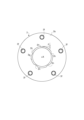
- the wheel pilot portion 3g is formed in a cylindrical shape, and a concave portion 3h having an arcuate cross-sectional view is provided on the outer peripheral surface of the wheel pilot portion 3g.
- the recessed portion 3h is formed from the outer end surface of the outer peripheral surface of the wheel pilot portion 3g to the base end portion 3i of the wheel mounting flange 3b. Further, as shown in FIG. 1, a radius is formed at the base end portion 3i.
- the R dimension of the base end portion 3i that is, the R dimension of the raised portion between the wheel mounting flange 3b and the wheel pilot portion 3g is formed to be 2 mm or more and 5 mm or less.
- the recess 3h is formed in an arcuate cross-sectional view.
- the cross-sectional shape of the recess 3h is not limited to an arc shape, and may be, for example, a partial elliptical shape in cross-sectional view.
- the radius of the concave portion 3h is preferably 6 mm or more. That is, it is configured to have a radius that allows the tool to be guided into the space formed between the recessed portion 3h and the inner diameter surface of the wheel or brake component.
- a chamfered portion is provided at a portion where both ends of the recess 3h in the circumferential direction are continuous with the outer peripheral surface, that is, at the edge of the outer peripheral surface of the recess 3h.
- the chamfered portion is processed into a curved surface shape, and it is possible to prevent the mating member from being damaged at the contact portion between the outer peripheral surface of the recessed portion 3h and the inner diameter surface of the wheel or brake component.
- the recessed portion 3h is formed so that the depth d from the outermost surface of the outer peripheral surface is 1 to 3 mm.
- the depth d is the length from the innermost portion of the arcuate recess 3h to the outer peripheral surface in a cross-sectional view.
- the recesses 3h are arranged at regular intervals along the circumferential direction when viewed in the axial direction. In other words, the recessed portions 3h are evenly distributed on concentric circles centered on the rotation axis X when viewed from the front.
- five recesses 3h are provided on the outer peripheral surface of the wheel pilot portion 3g, and the ratio of the total peripheral length of the recesses 3h to the outer peripheral length of the wheel pilot portion 3g is 35 to 75%. If the ratio of the total peripheral length of the recess 3h to the outer peripheral length of the wheel pilot portion 3g is less than 35%, there is no choice of where to guide the tool in the space formed between the recess 3h and the inner diameter surface of the wheel or brake component. narrows.
- the ratio of the total circumferential length of the recessed portion 3h to the outer circumferential length of the wheel pilot portion 3g is greater than 75%, it will not be able to serve as a guide for the wheel or brake component, resulting in looseness, or , it becomes difficult to ensure perpendicularity.
- the ratio of the total circumferential length of the recessed portion 3h to the outer circumferential length of the wheel pilot portion 3g is 35 to 75%, the weight of the wheel pilot portion 3g can be reduced. It can serve as a guide for wheels or brake components.
- the recess 3h can also be arranged in a state of being out of phase with the bolt hole 3f in the circumferential direction when viewed in the axial direction. Due to the phase difference, the recess 3h and the bolt hole 3f are arranged so as not to exist on the same radius.
- the recess 3h is arranged on a radius that is rotated by an angle b from the radius on which the bolt hole 3f is arranged. With this configuration, the tool can be guided into the space formed between the recess 3h and the inner diameter surface of the wheel or brake component without contact between the hub bolt 3e and the tool.
- the number of hub bolts 3e and the number of recesses 3h are arranged to be the same, but the present invention is not limited to this.
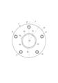
- the recess 3h can be arranged asymmetrically when viewed in the axial direction. In other words, it is also possible to arrange so that there are places where the arrangement positions along the circumferential direction of the recesses 3h are not at regular intervals.
- three recesses 3h are provided on the upper semicircle side, and two recesses 3h are arranged on the lower semicircle side.
- the center of gravity of the wheel pilot portion 3g moves downward, and the portions where sticking occurs become uneven.
- the recessed portions 3h may not be arranged at the places where rust occurs on the outer peripheral surface of the wheel pilot portion 3g.
- the problem can be solved by shortening the distance between adjacent recesses 3h and increasing the number of recesses 3h. Therefore, it is possible to dispose the concave portions 3h unevenly, insert a tool on the side opposite to the portion where the fixing area is large, and remove the fixing by the principle of leverage. In other words, it is possible to insert a tool into the side where the distance between the recesses 3h is wide and the side where the distance between the recesses 3h is narrow, which is the opposite side, and remove the fixation by the principle of leverage.
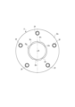
- the recesses 3h can be arranged asymmetrically in the axial view, and a lightening hole 3j can be provided in the lower half of the wheel mounting flange 3b.
- a lightening hole 3j can be provided in the lower half of the wheel mounting flange 3b.
- four recesses 3h are provided on the upper semicircle side, and two recesses 3h are arranged on the lower semicircle side.
- a single lightening hole 3j is arranged directly below the rotation axis X in the lower half of the wheel mounting flange 3b. Note that the number and arrangement of the lightening holes 3j are not limited to those in the embodiment. As a result, the position of the center of gravity of the wheel pilot portion 3g is adjusted, and the portions where sticking occurs become non-uniform.
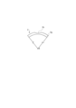
- a projection 13c can be provided on the inner diameter of the brake rotor 13, which is a brake component.
- the brake rotor 13, which is one of the brake parts has a brake-side mounting flange 13a that joins with the wheel mounting flange 3b, and a brake rotor main body 13b that fits with the wheel pilot portion 3g.
- a protrusion 13c is provided on the inner diameter surface of the brake rotor main body 13b.
- the protrusion 13c is formed in an arc shape in a cross-sectional view, and is arranged directly above the rotation axis X. Further, one recess 3h provided in the wheel pilot portion 3g is arranged directly above the rotation axis X. As shown in FIG.
- the radius of the protrusion 13c is formed to be substantially the same as or smaller than the radius of the recess 3h.
- the surface roughness of the protrusion 13c is preferably Ra 6.3 or less.
- the flange deflection between the wheel mounting flange 3b and the brake-side mounting flange 13a is 0.1 mm or less.
- the brake rotor 13 which is a brake component, is used as a member to be fitted with the wheel pilot portion 3g, but the present invention is not limited to this. may be
- a plating coating is applied to the outer peripheral surface of the wheel pilot portion 3g.
- the plating coating is applied to a portion of the outer peripheral surface of the wheel pilot portion 3g that comes into contact with the wheel or brake component.
- the wheel bearing device 1 in this embodiment is configured as a wheel bearing device 1 of a third-generation structure in which the inner raceway surface 3c is directly formed on the outer circumference of the hub wheel 3, but is limited to this. Instead, a second-generation structure in which a pair of inner rings 4 are press-fitted and fixed to the hub wheel 3 may be used.
- the wheel bearing device 1 of this embodiment is configured as a hub bolt type wheel bearing device 1 in which hub bolts 3e are press-fitted into bolt holes 3f, which are a plurality of insertion holes formed in the wheel mounting flange 3b.
- hub bolts 3e are press-fitted into bolt holes 3f, which are a plurality of insertion holes formed in the wheel mounting flange 3b.
- it is not limited to this, and it may be a wheel bolt type wheel bearing device in which a bolt is press-fitted into the mounting flange on the wheel side and a bolt hole for screwing the bolt is provided on the hub wheel side.
- the concave portion 3h may be arranged at any position.
- the present invention can be used for wheel bearing devices.
- Wheel bearing device Outer ring 2a Inner side opening 2c (Inner side) Outer raceway surface 2d (Outer side) Outer raceway surface 3 Hub ring 3a Small diameter stepped portion 3c (Hub ring) Inner raceway surface 3d Seal land 3e hub bolt 3f bolt hole 3g wheel pilot portion 3h concave portion 3i base end portion 3j lightening hole 4 inner ring 4a (inner ring) inner raceway surface 5 inner side ball row 6 outer side ball row 11 magnetic encoder 12 sensor holder 13 brake rotor 13a brake side Mounting flange 13b Brake rotor body 13c Protrusion
Landscapes
- Engineering & Computer Science (AREA)
- General Engineering & Computer Science (AREA)
- Mechanical Engineering (AREA)
- Manufacturing & Machinery (AREA)
- Rolling Contact Bearings (AREA)
Abstract
Description
また、固着したホイール、ブレーキロータを無理に離隔させようとすると、ハブ輪のパイロット部を工具等で傷つけてしまい、再組付け時の干渉や傷部から発生したごみがホイール、ブレーキロータの取り付け面に入り込み、取り付けの直角性が失われる可能性がある。
ホイールの直角性が失われると、直進時に抵抗が発生し、タイヤが偏摩耗する恐れがある。
アウトボード側に車輪取付フランジを一体に有し、外周に軸方向に延びる円筒状の小径段部が形成されたハブ輪、およびこのハブ輪の小径段部に圧入された少なくとも一つの内輪とからなり、外周に前記複列の外側転走面に対向する複列の内側転走面が形成された内方部材と、
前記両転走面間に転動自在に収容された複列の転動体と、を備えた車輪用軸受装置において、
前記ハブ輪は、前記車輪取付フランジよりもアウトボード側に延びてホイールの内径面を案内するホイールパイロット部を有し、該ホイールパイロット部の外周面に、深さ1~3mmの凹部が形成される。
図1に示す車輪用軸受装置1は、本発明に係る車輪用軸受装置の一実施形態であり、自動車等の車両の懸架装置において車輪を回転自在に支持するものである。
ホイールパイロット部3gは、ホイールまたはブレーキ部品の内径面を案内するために、滑らかな内面を有することが望ましい。たとえば、組付け時にホイールパイロット部3gの内面を傷つけると、傷部から発生したごみがホイールまたはブレーキ部品の内径面に入り込み、取り付けの直角性が失われる可能性がある。取り付けの直角性が失われると、ホイールパイロット部3gの内面とホイールまたはブレーキ部品の内径面との間に干渉が発生し、異音が発生する。
また車輪取付フランジ3bとホイールパイロット部3gとの立ち上げ部のR寸法を5mm以下とすることで、ブレーキ部品の内径部ストレートとアールの隙間を確保することができ、工具と内径部の掛かり代を適切に保つことができる。
ホイールパイロット部3gの外周長に対する凹部3hの周長の合計の割合が35~75%となるように構成することにより、ホイールパイロット部3gの軽量化を図ることができ、さらにホイールパイロット部3gのホイールまたはブレーキ部品のガイドとしての役割を果たすことができる。
ホイールパイロット部3gに凹部3hを均一に設けた場合、ホイールパイロット部3gの外周面において錆が発生する箇所に凹部3hが配置されない場合がある。この場合、隣接する凹部3hの間隔を短くして凹部3hの数を増やすことで解決することができるが、凹部3hを加工する時間が多くなり加工性を損なう。
そこで、凹部3hの配置を不均一にし、固着面積が広い部分とは逆側に工具を入れ、てこの原理で固着を剥がすようにすることができる。言い換えれば、凹部3h同士の間隔が広い側と反対側の凹部3h同士の間隔が狭い側に工具を入れ、てこの原理で固着を剥がすようにすることができる。
この場合、車輪取付フランジ3b側にハブボルトを配設する必要がないため、凹部3hは任意の位置に配置してもよい。
2 外輪
2a インナー側開口部
2c (インナー側の)外側軌道面
2d (アウター側の)外側軌道面
3 ハブ輪
3a 小径段部
3c (ハブ輪の)内側軌道面
3d シールランド部
3e ハブボルト
3f ボルト孔
3g ホイールパイロット部
3h 凹部
3i 基端部
3j 軽量孔
4 内輪
4a (内輪の)内側軌道面
5 インナー側ボール列
6 アウター側ボール列
11 磁気エンコーダ
12 センサホルダ
13 ブレーキロータ
13a ブレーキ側取付フランジ
13b ブレーキロータ本体
13c 突起
Claims (8)
- 内周に複列の外側転走面が形成された外方部材と、
アウトボード側に車輪取付フランジを一体に有し、外周に軸方向に延びる円筒状の小径段部が形成されたハブ輪、およびこのハブ輪の小径段部に圧入された少なくとも一つの内輪とからなり、外周に前記複列の外側転走面に対向する複列の内側転走面が形成された内方部材と、
前記両転走面間に転動自在に収容された複列の転動体と、を備えた車輪用軸受装置において、
前記ハブ輪は、前記車輪取付フランジよりもアウトボード側に延びてホイールの内径面を案内するホイールパイロット部を有し、該ホイールパイロット部の外周面に、深さ1~3mmの凹部が形成される
ことを特徴とする車輪用軸受装置。 - 前記車輪取付フランジにハブボルトを貫入するための挿通孔を設け、前記挿通孔と前記凹部との軸方向視における周方向の位相がずれている請求項1に記載の車輪用軸受装置。
- 前記凹部は軸方向を中心として非対称に配置され、
前記車輪取付フランジに前記ハブ輪の重心位置調整のための軽量孔を設ける請求項1または2に記載の車輪用軸受装置。 - 前記ホイールパイロットの外周長に対する前記凹部の周長の合計の割合は35~75%である請求項1から3のいずれか一項に記載の車輪用軸受装置。
- 前記車輪取付フランジと前記ホイールパイロット部との立ち上げ部のR寸法は2mm以上、5mm以下とする請求項1から4のいずれか一項に記載の車輪用軸受装置。
- 前記凹部の外周面側縁部に面取り部を設ける請求項1から5のいずれか一項に記載の車輪用軸受装置。
- 前記ホイールパイロットの前記外周面にメッキ面が塗装により形成される請求項1から6のいずれか一項に記載の車輪用軸受装置。
- 前記車輪取付フランジにホイールボルトを螺挿するためのボルト孔を設けた請求項1に記載の車輪用軸受装置。
Priority Applications (1)
| Application Number | Priority Date | Filing Date | Title |
|---|---|---|---|
| CN202380019507.9A CN118632786A (zh) | 2022-02-04 | 2023-01-05 | 车轮用轴承装置 |
Applications Claiming Priority (2)
| Application Number | Priority Date | Filing Date | Title |
|---|---|---|---|
| JP2022016400A JP7754738B2 (ja) | 2022-02-04 | 2022-02-04 | 車輪用軸受装置 |
| JP2022-016400 | 2022-02-04 |
Publications (1)
| Publication Number | Publication Date |
|---|---|
| WO2023149151A1 true WO2023149151A1 (ja) | 2023-08-10 |
Family
ID=87552248
Family Applications (1)
| Application Number | Title | Priority Date | Filing Date |
|---|---|---|---|
| PCT/JP2023/000033 Ceased WO2023149151A1 (ja) | 2022-02-04 | 2023-01-05 | 車輪用軸受装置 |
Country Status (3)
| Country | Link |
|---|---|
| JP (1) | JP7754738B2 (ja) |
| CN (1) | CN118632786A (ja) |
| WO (1) | WO2023149151A1 (ja) |
Citations (8)
| Publication number | Priority date | Publication date | Assignee | Title |
|---|---|---|---|---|
| JP2007147085A (ja) * | 2007-02-19 | 2007-06-14 | Ntn Corp | 転がり軸受 |
| JP2007223563A (ja) * | 2006-02-27 | 2007-09-06 | Ntn Corp | 車輪用軸受装置 |
| JP2008030554A (ja) * | 2006-07-27 | 2008-02-14 | Ntn Corp | 車輪用軸受装置 |
| JP2008030645A (ja) * | 2006-07-31 | 2008-02-14 | Ntn Corp | 車輪用軸受装置 |
| JP2009008165A (ja) * | 2007-06-28 | 2009-01-15 | Ntn Corp | 車輪用軸受装置 |
| JP2012197043A (ja) * | 2011-03-22 | 2012-10-18 | Ntn Corp | 車輪用軸受装置およびその製造方法 |
| JP2021088235A (ja) * | 2019-12-03 | 2021-06-10 | 株式会社ジェイテクト | 車輪用軸受装置及び車輪の取付方法 |
| JP2021109545A (ja) * | 2020-01-10 | 2021-08-02 | 日本精工株式会社 | ハブユニット軸受 |
-
2022
- 2022-02-04 JP JP2022016400A patent/JP7754738B2/ja active Active
-
2023
- 2023-01-05 CN CN202380019507.9A patent/CN118632786A/zh active Pending
- 2023-01-05 WO PCT/JP2023/000033 patent/WO2023149151A1/ja not_active Ceased
Patent Citations (8)
| Publication number | Priority date | Publication date | Assignee | Title |
|---|---|---|---|---|
| JP2007223563A (ja) * | 2006-02-27 | 2007-09-06 | Ntn Corp | 車輪用軸受装置 |
| JP2008030554A (ja) * | 2006-07-27 | 2008-02-14 | Ntn Corp | 車輪用軸受装置 |
| JP2008030645A (ja) * | 2006-07-31 | 2008-02-14 | Ntn Corp | 車輪用軸受装置 |
| JP2007147085A (ja) * | 2007-02-19 | 2007-06-14 | Ntn Corp | 転がり軸受 |
| JP2009008165A (ja) * | 2007-06-28 | 2009-01-15 | Ntn Corp | 車輪用軸受装置 |
| JP2012197043A (ja) * | 2011-03-22 | 2012-10-18 | Ntn Corp | 車輪用軸受装置およびその製造方法 |
| JP2021088235A (ja) * | 2019-12-03 | 2021-06-10 | 株式会社ジェイテクト | 車輪用軸受装置及び車輪の取付方法 |
| JP2021109545A (ja) * | 2020-01-10 | 2021-08-02 | 日本精工株式会社 | ハブユニット軸受 |
Also Published As
| Publication number | Publication date |
|---|---|
| JP2023114190A (ja) | 2023-08-17 |
| JP7754738B2 (ja) | 2025-10-15 |
| CN118632786A (zh) | 2024-09-10 |
Similar Documents
| Publication | Publication Date | Title |
|---|---|---|
| US7044563B2 (en) | Wheel supporting roller bearing unit and manufacturing method of the same | |
| JP2010100156A5 (ja) | ||
| KR20160118955A (ko) | 차륜 베어링 장치의 제조 방법 | |
| US20050157965A1 (en) | Bearing with tapered rolling bodies provided with a sealing device | |
| JP5549386B2 (ja) | 車輪用軸受装置 | |
| US20210331519A1 (en) | Bearing device for vehicle wheel | |
| WO2023149151A1 (ja) | 車輪用軸受装置 | |
| JP3925885B2 (ja) | ホイール用ハブユニット軸受 | |
| JP7327103B2 (ja) | アンギュラ玉軸受用保持器及びアンギュラ玉軸受 | |
| JP6376316B1 (ja) | 転がり軸受 | |
| JP7663384B2 (ja) | 車輪用軸受装置 | |
| JP4134872B2 (ja) | 転がり軸受装置 | |
| KR102938893B1 (ko) | 차륜용 베어링 장치 | |
| JP4771114B2 (ja) | ハブユニット | |
| JP7487642B2 (ja) | ハブユニット軸受 | |
| JP7787661B2 (ja) | 車輪用軸受装置 | |
| JP2008014473A (ja) | 車輪用軸受装置 | |
| CN110778601A (zh) | 车辆用轴承装置 | |
| US20050232526A1 (en) | Bearing unit for wheels | |
| JP2025134538A (ja) | 車輪用軸受装置 | |
| WO2024053511A1 (ja) | 車輪用軸受装置 | |
| JP2007327565A (ja) | 車輪用軸受装置 | |
| JP2025146507A (ja) | 密封装置 | |
| JP2025127973A (ja) | 密封装置及びそれを備えた車輪用軸受装置 | |
| JP2003042174A (ja) | 転がり軸受の取付け構造 |
Legal Events
| Date | Code | Title | Description |
|---|---|---|---|
| 121 | Ep: the epo has been informed by wipo that ep was designated in this application |
Ref document number: 23749468 Country of ref document: EP Kind code of ref document: A1 |
|
| WWE | Wipo information: entry into national phase |
Ref document number: 202380019507.9 Country of ref document: CN |
|
| NENP | Non-entry into the national phase |
Ref country code: DE |
|
| 32PN | Ep: public notification in the ep bulletin as address of the adressee cannot be established |
Free format text: NOTING OF LOSS OF RIGHTS PURSUANT TO RULE 112(1) EPC (EPO FORM 1205 DATED 12/11/2024) |
|
| 122 | Ep: pct application non-entry in european phase |
Ref document number: 23749468 Country of ref document: EP Kind code of ref document: A1 |