WO2023149090A1 - 蒸気弁の計測方法及び蒸気弁の計測装置 - Google Patents
蒸気弁の計測方法及び蒸気弁の計測装置 Download PDFInfo
- Publication number
- WO2023149090A1 WO2023149090A1 PCT/JP2022/045769 JP2022045769W WO2023149090A1 WO 2023149090 A1 WO2023149090 A1 WO 2023149090A1 JP 2022045769 W JP2022045769 W JP 2022045769W WO 2023149090 A1 WO2023149090 A1 WO 2023149090A1
- Authority
- WO
- WIPO (PCT)
- Prior art keywords
- valve
- steam
- child
- valve stem
- stem
- Prior art date
- Legal status (The legal status is an assumption and is not a legal conclusion. Google has not performed a legal analysis and makes no representation as to the accuracy of the status listed.)
- Ceased
Links
Images


Classifications
-
- F—MECHANICAL ENGINEERING; LIGHTING; HEATING; WEAPONS; BLASTING
- F16—ENGINEERING ELEMENTS AND UNITS; GENERAL MEASURES FOR PRODUCING AND MAINTAINING EFFECTIVE FUNCTIONING OF MACHINES OR INSTALLATIONS; THERMAL INSULATION IN GENERAL
- F16K—VALVES; TAPS; COCKS; ACTUATING-FLOATS; DEVICES FOR VENTING OR AERATING
- F16K39/00—Devices for relieving the pressure on the sealing faces
- F16K39/02—Devices for relieving the pressure on the sealing faces for lift valves
- F16K39/024—Devices for relieving the pressure on the sealing faces for lift valves using an auxiliary valve on the main valve
-
- F—MECHANICAL ENGINEERING; LIGHTING; HEATING; WEAPONS; BLASTING
- F01—MACHINES OR ENGINES IN GENERAL; ENGINE PLANTS IN GENERAL; STEAM ENGINES
- F01D—NON-POSITIVE DISPLACEMENT MACHINES OR ENGINES, e.g. STEAM TURBINES
- F01D17/00—Regulating or controlling by varying flow
- F01D17/10—Final actuators
-
- F—MECHANICAL ENGINEERING; LIGHTING; HEATING; WEAPONS; BLASTING
- F01—MACHINES OR ENGINES IN GENERAL; ENGINE PLANTS IN GENERAL; STEAM ENGINES
- F01D—NON-POSITIVE DISPLACEMENT MACHINES OR ENGINES, e.g. STEAM TURBINES
- F01D17/00—Regulating or controlling by varying flow
- F01D17/02—Arrangement of sensing elements
- F01D17/08—Arrangement of sensing elements responsive to condition of working-fluid, e.g. pressure
-
- F—MECHANICAL ENGINEERING; LIGHTING; HEATING; WEAPONS; BLASTING
- F01—MACHINES OR ENGINES IN GENERAL; ENGINE PLANTS IN GENERAL; STEAM ENGINES
- F01D—NON-POSITIVE DISPLACEMENT MACHINES OR ENGINES, e.g. STEAM TURBINES
- F01D17/00—Regulating or controlling by varying flow
- F01D17/10—Final actuators
- F01D17/12—Final actuators arranged in stator parts
- F01D17/14—Final actuators arranged in stator parts varying effective cross-sectional area of nozzles or guide conduits
- F01D17/141—Final actuators arranged in stator parts varying effective cross-sectional area of nozzles or guide conduits by means of shiftable members or valves obturating part of the flow path
- F01D17/145—Final actuators arranged in stator parts varying effective cross-sectional area of nozzles or guide conduits by means of shiftable members or valves obturating part of the flow path by means of valves, e.g. for steam turbines
-
- F—MECHANICAL ENGINEERING; LIGHTING; HEATING; WEAPONS; BLASTING
- F01—MACHINES OR ENGINES IN GENERAL; ENGINE PLANTS IN GENERAL; STEAM ENGINES
- F01K—STEAM ENGINE PLANTS; STEAM ACCUMULATORS; ENGINE PLANTS NOT OTHERWISE PROVIDED FOR; ENGINES USING SPECIAL WORKING FLUIDS OR CYCLES
- F01K13/00—General layout or general methods of operation of complete plants
- F01K13/02—Controlling, e.g. stopping or starting
-
- F—MECHANICAL ENGINEERING; LIGHTING; HEATING; WEAPONS; BLASTING
- F02—COMBUSTION ENGINES; HOT-GAS OR COMBUSTION-PRODUCT ENGINE PLANTS
- F02C—GAS-TURBINE PLANTS; AIR INTAKES FOR JET-PROPULSION PLANTS; CONTROLLING FUEL SUPPLY IN AIR-BREATHING JET-PROPULSION PLANTS
- F02C9/00—Controlling gas-turbine plants; Controlling fuel supply in air- breathing jet-propulsion plants
- F02C9/16—Control of working fluid flow
- F02C9/20—Control of working fluid flow by throttling; by adjusting vanes
-
- F—MECHANICAL ENGINEERING; LIGHTING; HEATING; WEAPONS; BLASTING
- F02—COMBUSTION ENGINES; HOT-GAS OR COMBUSTION-PRODUCT ENGINE PLANTS
- F02C—GAS-TURBINE PLANTS; AIR INTAKES FOR JET-PROPULSION PLANTS; CONTROLLING FUEL SUPPLY IN AIR-BREATHING JET-PROPULSION PLANTS
- F02C9/00—Controlling gas-turbine plants; Controlling fuel supply in air- breathing jet-propulsion plants
- F02C9/16—Control of working fluid flow
- F02C9/24—Control of the pressure level in closed cycles
-
- F—MECHANICAL ENGINEERING; LIGHTING; HEATING; WEAPONS; BLASTING
- F16—ENGINEERING ELEMENTS AND UNITS; GENERAL MEASURES FOR PRODUCING AND MAINTAINING EFFECTIVE FUNCTIONING OF MACHINES OR INSTALLATIONS; THERMAL INSULATION IN GENERAL
- F16K—VALVES; TAPS; COCKS; ACTUATING-FLOATS; DEVICES FOR VENTING OR AERATING
- F16K1/00—Lift valves or globe valves, i.e. cut-off apparatus with closure members having at least a component of their opening and closing motion perpendicular to the closing faces
- F16K1/32—Details
- F16K1/34—Cutting-off parts, e.g. valve members, seats
- F16K1/44—Details of seats or valve members of double-seat valves
- F16K1/443—Details of seats or valve members of double-seat valves the seats being in series
-
- F—MECHANICAL ENGINEERING; LIGHTING; HEATING; WEAPONS; BLASTING
- F16—ENGINEERING ELEMENTS AND UNITS; GENERAL MEASURES FOR PRODUCING AND MAINTAINING EFFECTIVE FUNCTIONING OF MACHINES OR INSTALLATIONS; THERMAL INSULATION IN GENERAL
- F16K—VALVES; TAPS; COCKS; ACTUATING-FLOATS; DEVICES FOR VENTING OR AERATING
- F16K37/00—Special means in or on valves or other cut-off apparatus for indicating or recording operation thereof, or for enabling an alarm to be given
- F16K37/0025—Electrical or magnetic means
- F16K37/0033—Electrical or magnetic means using a permanent magnet, e.g. in combination with a reed relays
-
- F—MECHANICAL ENGINEERING; LIGHTING; HEATING; WEAPONS; BLASTING
- F16—ENGINEERING ELEMENTS AND UNITS; GENERAL MEASURES FOR PRODUCING AND MAINTAINING EFFECTIVE FUNCTIONING OF MACHINES OR INSTALLATIONS; THERMAL INSULATION IN GENERAL
- F16K—VALVES; TAPS; COCKS; ACTUATING-FLOATS; DEVICES FOR VENTING OR AERATING
- F16K37/00—Special means in or on valves or other cut-off apparatus for indicating or recording operation thereof, or for enabling an alarm to be given
- F16K37/0025—Electrical or magnetic means
- F16K37/0041—Electrical or magnetic means for measuring valve parameters
-
- F—MECHANICAL ENGINEERING; LIGHTING; HEATING; WEAPONS; BLASTING
- F16—ENGINEERING ELEMENTS AND UNITS; GENERAL MEASURES FOR PRODUCING AND MAINTAINING EFFECTIVE FUNCTIONING OF MACHINES OR INSTALLATIONS; THERMAL INSULATION IN GENERAL
- F16K—VALVES; TAPS; COCKS; ACTUATING-FLOATS; DEVICES FOR VENTING OR AERATING
- F16K37/00—Special means in or on valves or other cut-off apparatus for indicating or recording operation thereof, or for enabling an alarm to be given
- F16K37/0075—For recording or indicating the functioning of a valve in combination with test equipment
- F16K37/0083—For recording or indicating the functioning of a valve in combination with test equipment by measuring valve parameters
-
- F—MECHANICAL ENGINEERING; LIGHTING; HEATING; WEAPONS; BLASTING
- F05—INDEXING SCHEMES RELATING TO ENGINES OR PUMPS IN VARIOUS SUBCLASSES OF CLASSES F01-F04
- F05D—INDEXING SCHEME FOR ASPECTS RELATING TO NON-POSITIVE-DISPLACEMENT MACHINES OR ENGINES, GAS-TURBINES OR JET-PROPULSION PLANTS
- F05D2260/00—Function
- F05D2260/83—Testing, e.g. methods, components or tools therefor
-
- F—MECHANICAL ENGINEERING; LIGHTING; HEATING; WEAPONS; BLASTING
- F05—INDEXING SCHEMES RELATING TO ENGINES OR PUMPS IN VARIOUS SUBCLASSES OF CLASSES F01-F04
- F05D—INDEXING SCHEME FOR ASPECTS RELATING TO NON-POSITIVE-DISPLACEMENT MACHINES OR ENGINES, GAS-TURBINES OR JET-PROPULSION PLANTS
- F05D2270/00—Control
- F05D2270/30—Control parameters, e.g. input parameters
- F05D2270/301—Pressure
- F05D2270/3011—Inlet pressure
-
- F—MECHANICAL ENGINEERING; LIGHTING; HEATING; WEAPONS; BLASTING
- F05—INDEXING SCHEMES RELATING TO ENGINES OR PUMPS IN VARIOUS SUBCLASSES OF CLASSES F01-F04
- F05D—INDEXING SCHEME FOR ASPECTS RELATING TO NON-POSITIVE-DISPLACEMENT MACHINES OR ENGINES, GAS-TURBINES OR JET-PROPULSION PLANTS
- F05D2270/00—Control
- F05D2270/30—Control parameters, e.g. input parameters
- F05D2270/306—Mass flow
- F05D2270/3061—Mass flow of the working fluid
-
- F—MECHANICAL ENGINEERING; LIGHTING; HEATING; WEAPONS; BLASTING
- F16—ENGINEERING ELEMENTS AND UNITS; GENERAL MEASURES FOR PRODUCING AND MAINTAINING EFFECTIVE FUNCTIONING OF MACHINES OR INSTALLATIONS; THERMAL INSULATION IN GENERAL
- F16K—VALVES; TAPS; COCKS; ACTUATING-FLOATS; DEVICES FOR VENTING OR AERATING
- F16K2200/00—Details of valves
- F16K2200/20—Common housing having a single inlet, a single outlet and multiple valve members
- F16K2200/202—Common housing having a single inlet, a single outlet and multiple valve members one valve arranged inside of the valve member of a second valve, e.g. nested valve members
-
- Y—GENERAL TAGGING OF NEW TECHNOLOGICAL DEVELOPMENTS; GENERAL TAGGING OF CROSS-SECTIONAL TECHNOLOGIES SPANNING OVER SEVERAL SECTIONS OF THE IPC; TECHNICAL SUBJECTS COVERED BY FORMER USPC CROSS-REFERENCE ART COLLECTIONS [XRACs] AND DIGESTS
- Y02—TECHNOLOGIES OR APPLICATIONS FOR MITIGATION OR ADAPTATION AGAINST CLIMATE CHANGE
- Y02E—REDUCTION OF GREENHOUSE GAS [GHG] EMISSIONS, RELATED TO ENERGY GENERATION, TRANSMISSION OR DISTRIBUTION
- Y02E30/00—Energy generation of nuclear origin
- Y02E30/30—Nuclear fission reactors
Definitions
- the present disclosure relates to a steam valve measurement method and a steam valve measurement device.
- This application claims priority based on Japanese Patent Application No. 2022-014366 filed with the Japan Patent Office on February 1, 2022, the content of which is incorporated herein.
- a steam valve typically includes a valve seat having an opening, a valve stem for moving a valve disc provided facing the opening of the valve seat in a direction toward and away from the valve seat, and a sliding member for sliding the valve stem. and a cylindrical support member for movably supporting (see, for example, Patent Document 1).
- At least one embodiment of the present disclosure aims to provide a steam valve measurement method and a steam valve measurement device that can relatively easily confirm the progress of wear of the steam valve.
- a steam valve measurement method includes: a valve body having a steam flow path through which steam flows and a valve seat provided in the middle of the steam flow path and having an opening; a valve stem extending in the axial direction of the axis and capable of advancing and retracting in the axial direction; a child valve provided at the tip of the valve stem in the tip of the valve stem; and a tip of the valve stem , a penetrating portion into which a portion positioned closer to the base end of the valve stem than the tip end is inserted, and closes the steam flow path by contacting the valve seat, and when the child valve is opened, a stop valve having a parent valve formed with a through hole through which the steam flows; an actuator that drives the valve stem;
- a method for measuring a steam valve comprising: a step of measuring the acceleration of the valve stem when the valve stem is driven by the actuator from the fully closed state of the parent valve and the child valve to open the child valve; detecting the timing at which the child valve is fully opened
- a steam valve measuring device a valve body having a steam flow path through which steam flows and a valve seat provided in the middle of the steam flow path and having an opening; a valve stem extending in the axial direction of the axis and capable of advancing and retracting in the axial direction; a child valve provided at the tip of the valve stem in the tip of the valve stem; and a tip of the valve stem , a penetrating portion into which a portion positioned closer to the base end of the valve stem than the tip end is inserted, and closes the steam flow path by contacting the valve seat, and when the child valve is opened, a stop valve having a parent valve formed with a through hole through which the steam flows; an actuator that drives the valve stem;
- a steam valve measuring device comprising: an acceleration sensor for measuring acceleration of the valve stem; a first detection unit that detects the timing at which the child valve is fully opened based on the acceleration of the valve stem measured by the acceleration sensor; a calculation unit that calculates the amount of movement
- FIG. 1 is a schematic configuration diagram of a power generation system according to one embodiment
- FIG. FIG. 2 is a cross-sectional view showing the configuration of a steam valve according to one embodiment with both the child valve and the parent valve closed.
- 3 is an enlarged view of area A of FIG. 2
- FIG. 3B is a schematic diagram showing a state in which the child valve is first opened while the parent valve is closed in the steam valve shown in FIG. 3A
- 4 is a functional block diagram of a controller according to some embodiments
- FIG. 4 is a flow chart showing the procedure of processing in the steam valve measurement method according to the first embodiment.
- 4 is a graph showing measurement results of valve stem strain by a strain sensor and measurement results of valve stem acceleration by an acceleration sensor, where the horizontal axis represents the amount of movement of the valve stem. 4 is a graph showing an example of transition of an estimated valve stroke.
- 9 is a flow chart showing a procedure of processing in a method for measuring a steam valve according to the second embodiment; 3 is an enlarged view of area B of FIG. 2; FIG. 3 is an enlarged view of area B of FIG. 2; FIG. It is a figure which shows the apparatus structure for enforcing the measuring method of the steam valve which concerns on 3rd Embodiment.
- FIG. 11 is a flow chart showing a procedure of processing in a method for measuring a steam valve according to the fourth embodiment
- expressions that express shapes such as squares and cylinders do not only represent shapes such as squares and cylinders in a geometrically strict sense, but also include irregularities and chamfers to the extent that the same effect can be obtained. Shapes including parts etc. shall also be represented.
- the expressions “comprising”, “comprising”, “having”, “including”, or “having” one component are not exclusive expressions excluding the presence of other components.
- FIG. 1 is a schematic configuration diagram of a power generation system 1 according to one embodiment.
- the power generation system 1 includes a steam turbine 10 , a boiler 11 and a generator 26 .
- the steam turbine 10 is a turbine driven by the steam generated by the boiler 11.
- the steam turbine 10 is connected to a boiler 11 via a first steam supply pipe 12 and is driven by being supplied with high-pressure steam generated by burning fuel in the boiler 11 .
- a steam valve 14 for adjusting the flow rate of steam supplied to the steam turbine 10 is provided in the first steam supply pipe 12 .
- the structure of the steam valve 14, which will be described in detail later, includes a control valve 43 and a stop valve 45. As shown in FIG.
- a multi-stage turbine is exemplified as the steam turbine 10, and the steam turbine 10 includes a high-pressure steam turbine 31, an intermediate-pressure steam turbine 32, and a low-pressure steam turbine 33 from the upstream side with respect to the steam flow path.
- the high-pressure steam turbine 31 is driven by steam supplied from the first steam supply pipe 12 (high-pressure steam generated by the boiler 11).
- the steam that has finished work in the high pressure steam turbine 31 is supplied to the intermediate pressure steam turbine 32 via the second steam supply pipe 16 .
- a reheater 18 is provided in the second steam supply pipe 16 .
- the intermediate-pressure steam turbine 32 is driven by steam supplied from the second steam supply pipe 16 (steam that has finished work in the high-pressure steam turbine 31).
- the steam that has finished work in the intermediate pressure steam turbine 32 is supplied to the low pressure steam turbine 33 via the third steam supply pipe 25 .
- the low-pressure steam turbine 33 is driven by steam supplied from the third steam supply pipe 25 (steam that has finished work in the intermediate-pressure steam turbine 32).
- Each turbine (high-pressure steam turbine 31 , intermediate-pressure steam turbine 32 , and low-pressure steam turbine 33 ) that constitute the steam turbine 10 has a common rotating shaft 35 .
- a generator 26 is connected to the rotating shaft 35, and the generator 26 is driven by rotation of each turbine to generate power.
- FIGS. 2 to 4B are cross-sectional views showing the configuration of the steam valve 14 according to one embodiment with both the child valve 62 and the parent valve 64 closed
- FIG. 3A is an enlarged view of area A in FIG.
- FIG. 3B is a schematic diagram showing a state in which the child valve 62 is first opened while the parent valve 64 is closed in the steam valve 14 shown in FIG. 3A.
- O1 is the axis of the valve stem 61 that constitutes the stop valve 45
- O2 is the axis of the valve stem 55 that constitutes the control valve 43.
- axial direction Z is, for example, a substantially vertical direction.
- the steam valve 14 includes a valve body 41, a control valve 43, a stop valve 45, and actuators 46A and 46B.
- the valve body 41 has a flow path dividing portion 47 and a valve seat 48 .
- the channel partitioning portion 47 partitions the steam channel 52 and accommodates part of the control valve 43 (front end side) and part of the stop valve 45 (front end side).
- the steam flow path 52 has an inlet portion 52A and an outlet portion 52B.
- the inlet portion 52A is connected to the boiler 11 through one side of the first steam supply pipe 12, and high-pressure steam generated by the boiler 11 is introduced.
- the outlet portion 52B is connected to the high pressure steam turbine 31 via the other side of the first steam supply pipe 12 .
- the amount of steam supplied from the boiler 11 to the high-pressure steam turbine 31 via the first steam supply pipe 12 is controlled by the control valve 43 in the steam valve 14 provided in the first steam supply pipe 12 when the stop valve 45 is open. It is adjustable by controlling the degree of opening.
- the actuators 46A and 46B are hydraulic actuators that can be driven by pressure oil.
- the flow path dividing portion 47 includes a first guide member 47A and a second guide member 47B.
- 47 A of 1st guide members are provided so that the outer peripheral surface of the part which is not exposed to the steam flow path 52 among the valve stems 55 which comprise the control valve 43 may be covered.
- the first guide member 47A functions as a guide that guides the valve stem 55 in the axial direction Z.
- the second guide member 47B is provided so as to cover the outer peripheral surface of the rod-shaped portion 61B that constitutes the stop valve 45.
- the second guide member 47B functions as a guide that guides the valve stem 61 in the axial direction Z.
- the valve seat 48 is provided in the channel dividing portion 47 located in the middle of the steam channel 52 .
- the valve seat 48 has a ring shape centered on the axis O1, and is configured such that the axis of the valve seat 48 coincides with the axis O1.
- the valve seat 48 has a valve seat surface 48 a exposed to the steam flow path 52 .
- the valve seat surface 48a is, for example, a curved surface.
- control valve 43 The control valve 43 is arranged upstream of the position where the stop valve 45 is arranged in the steam flow direction.
- the control valve 43 has a valve stem 55 and a control valve main body 56 .
- the valve stem 55 extends in the axial direction Z, and the tip side thereof is arranged in the steam flow path 52 .
- the axis O ⁇ b>1 of the valve stem 55 is configured to coincide with the axis O ⁇ b>2 of the valve stem 55 of the stop valve 45 .
- the valve stem 55 is movable in the axial direction Z.
- the control valve main body 56 is provided on the tip side of the valve stem 55 .
- a portion of the control valve main body 56 located on the side of the valve seat 48 has a cylindrical shape and has a tip 56A capable of contacting the valve seat surface 48a of the valve seat 48 .
- the control valve 43 having such a configuration controls the distance between the tip 56A of the control valve main body 56 and the valve seat 48 by moving the valve rod 55 along the axial direction Z with the actuator 46A, thereby controlling the steam flow. It has a function of adjusting the flow rate of high-pressure steam supplied to the high-pressure steam turbine 31 according to the load of the turbine 10 .
- the stop valve 45 is arranged inside the control valve 43 .
- the stop valve 45 includes a valve stem 61 , a child valve 62 and a parent valve 64 .
- the valve stem 61 extends in the axial direction Z and has a tip portion 61A and a rod-shaped portion 61B.
- the distal end portion 61A has a shape that can be engaged with the child valve 62 for fixing the child valve 62 .
- the bar-shaped portion 61B extends along the axial direction Z.
- a base end portion of the bar-shaped portion 61B is connected to the actuator 46B via the actuator crosshead 49.
- the valve stem 61 having the tip portion 61A and the rod-like portion 61B is integrally constructed and can move back and forth in the axial direction Z. As shown in FIG.
- the child valve 62 has a contact portion 621.
- the child valve 62 is fixed to the tip portion 61A of the valve stem 61 .
- the contact portion 621 constitutes the outer peripheral portion of the child valve 62 .
- the contact portion 621 extends obliquely downward and has a ring shape when viewed from the axial direction Z. As shown in FIG.
- the contact portion 621 contacts the valve seat surface 71a formed on the parent valve main body 71 constituting the parent valve 64 .
- the inlet 71Ba of the through-hole 71B is isolated from the steam passage 52 through which high-pressure steam flows, so high-pressure steam does not flow through the through-hole 71B.
- the stop valve 45 is opened before the control valve 43 is opened.
- the stop valve 45 as shown in FIGS. 2 and 3A, the child valve 62 and the parent valve 64 are both closed, and as shown in FIG. (parent valve 64 remains closed).
- the abutment portion 621 of the child valve 62 is separated from the valve seat surface 71a, a gap is formed between the child valve 62 and the main valve 64, so that high-pressure steam enters the inlet 71Ba of the through hole 71B. influx.
- the high-pressure steam that has flowed into the inlet 71Ba of the through hole 71B is led out to the steam flow path 52 from the outlet 71Bb of the through hole 71B.
- the differential pressure between the upstream and downstream sides of the main valve 64 is reduced, and the subsequent opening operation of the main valve 64 is facilitated.
- the parent valve 64 is inserted into the valve stem 61 and arranged between the child valve 62 and the rod-shaped portion 61B.
- the parent valve 64 has a parent valve body 71 .
- the parent valve main body 71 has a substantially V shape when viewed in longitudinal section.
- the parent valve main body 71 has a through portion 71A, a valve seat surface 71a, a contact surface 71b, and a plurality of through holes 71B.
- the through portion 71A is formed so as to pass through the central portion of the parent valve main body 71 in the axial direction Z.
- the through portion 71A is, for example, a cylindrical hole and is defined by an inner peripheral surface 71c.
- the tip portion 61A of the valve stem 61 is inserted through the through portion 71A.
- a bush (not shown) may be arranged in the through portion 71A.
- the inner peripheral surface 71c is in contact with the outer peripheral surface of the valve stem 61 while the tip portion 61A of the valve stem 61 is movable in the axial direction Z. As shown in FIG.
- valve stem 61 is a valve in which the outer diameter of the valve stem 61 expands from the distal end side to the proximal end side in a region where the outer peripheral surface is covered with the inner peripheral surface 71c of the main valve main body 71. It has a rod ramp 619 .
- the valve stem inclined surface 619 is a conical inclined surface.
- the parent valve main body 71 has a contact surface 711 that can contact the valve stem inclined surface 619 of the valve stem 61 as shown in FIG. 3B.
- the contact surface 711 is a conical surface formed so that the inner diameter of the contact surface 711 increases from the distal end side toward the proximal end side.
- the valve seat surface 71a is a curved surface arranged on the child valve 62 side (the tip side of the valve stem 61). Among the valve seat surfaces 71a, the surfaces positioned radially outward from the inlets 71Ba of the plurality of through holes 71B with respect to the axis O1 of the valve stem 60, when the child valve 62 is closed (Fig. 2 and 3A), the abutment portion 621 of the child valve 62 is abutted.
- the contact surface 71b is a curved surface arranged on the proximal end side of the valve stem 61.
- the outer peripheral portion of the contact surface 71b contacts the valve seat surface 48a of the valve seat 48 when the parent valve 64 is fully closed. In this state, high-pressure steam does not flow downstream of the valve seat 48 .
- the contact surface 71b and the valve seat surface 48a are separated from each other, and a gap is formed between the contact surface 71b and the valve seat surface 48a. Steam of high pressure corresponding to the degree of opening of the control valve 43 flows downstream.
- a plurality of through holes 71B are formed through the main valve main body 71 so as to reach the contact surface 71b from the valve seat surface 71a.
- the plurality of through holes 71B are arranged in the circumferential direction of the main valve main body 71 .
- the through hole 71B has an inlet 71Ba and an outlet 71Bb.
- the inlet 71Ba is formed on the valve seat surface 71a located radially inward about the axis O1 of the valve stem 60 from the contact position between the contact portion 62B and the valve seat surface 71a.
- FIG. 3B when the child valve 62 opens prior to the parent valve 64 and a gap is formed between the child valve 62 and the parent valve 64, a high pressure is applied to the through hole 71B through the inlet 71Ba. Steam flows in.
- the outlet 71Bb is formed on the contact surface 71b positioned radially outward of the axis O1 from the formation position of the inlet 71Ba.
- the outlet 71Bb communicates with the steam flow path 52 located downstream of the valve seat 48 .
- the through-hole 71B of this embodiment is inclined in the direction from the inlet 71Ba to the outlet 71Bb.
- stop valve 45 operates as follows. In the steam valve 14 , the stop valve 45 is opened before the control valve 43 is opened when the flow rate of steam is adjusted by the control valve 43 .
- valve stem inclined surface 619 of the valve stem 61 and the contact surface 711 of the parent valve main body 71 are separated in the axial direction Z.
- valve stem 61 is driven toward the proximal side by the actuator 46B, and the main valve 64 and the child valve 62 move toward the proximal side together with the valve stem 61 .
- the parent valve body 71 abuts against the valve seat surface 48 a of the valve seat 48 to close the parent valve 64 .
- the valve stem 61 is driven toward the proximal end by the actuator 46B, so that the valve stem inclined surface 619 of the valve stem 61 and the contact surface 711 of the main valve main body 71 are separated. do.
- the child valve 62 is closed when the valve seat surface 71a of the main valve main body 71 and the contact portion 621 of the child valve 62 come into contact with each other.
- the steam valve 14 to which the steam valve measuring method according to some embodiments described later is applied includes the valve main body 41, the stop valve 45, and the actuator 46B that drives the valve stem 61, as described above.
- the valve body 41 has a steam flow path 52 through which steam flows, and a valve seat 48 provided in the middle of the steam flow path 52 and having an opening.
- the stop valve 45 extends in the axial direction Z along which the axes O1 and O2 extend, and includes a valve stem 61 that can move back and forth in the axial direction Z, and a tip portion 61A of the valve stem 61.
- a through portion 71A into which a portion of the valve 62 and the tip portion 61A of the valve stem 61 located closer to the base end of the valve stem 61 than the tip is inserted is inserted. It has a parent valve 64 that closes the passage 52 and has a through hole 71B through which steam flows when the child valve 62 is opened. (Regarding wear of steam valve 14)
- the valve stem inclined surface 619 of the valve stem 61 and the contact surface 711 of the main valve main body 71 contact and separate each time the stop valve 45 is opened and closed. repeat.
- valve stem inclined surface 619 of the valve stem 61 and the contact surface 711 of the main valve main body 71 are housed inside the valve casing (valve body 41), which is a high-pressure container. was stopped and the steam valve 14 was disassembled, the progress of wear could not be grasped.
- valve stem inclined surface 619 of the valve stem 61 and the contact surface 711 of the main valve main body 71 when the stop valve 45 is fully closed may The distance in the axial direction Z from the contact surface 711 of the parent valve main body 71 increases. Therefore, when the wear between the valve stem inclined surface 619 of the valve stem 61 and the contact surface 711 of the main valve main body 71 progresses, the valve stem as shown in FIG. The amount of movement of the valve stem 61 increases until the valve stem inclined surface 619 of the valve stem 61 and the contact surface 711 of the parent valve main body 71 come into contact with each other and the child valve 62 is fully opened.
- FIG. 2 shows an apparatus configuration for implementing the steam valve measurement method according to the first embodiment. That is, the steam valve measuring device 100 according to the first embodiment includes an acceleration sensor 101 , a strain sensor 103 , a displacement gauge 105 , and a control device 110 .
- the acceleration sensor 101 is an acceleration sensor for measuring the acceleration of the valve stem 61.
- the acceleration sensor 101 is attached, for example, to a base end portion 61C of the valve stem 61 protruding outside from the valve casing (valve main body 41).
- the strain sensor 103 is a strain gauge for measuring the strain of the valve stem 61, for example.
- the strain sensor 103 is attached to the base end portion 61C of the valve stem 61, for example.
- the displacement gauge 105 is a displacement sensor for measuring the amount of movement (displacement) of the valve stem 61 .
- the displacement gauge 105 is arranged outside the valve casing (valve main body 41), and measures the distance to a displacement gauge target 105a attached to the base end portion 61C of the valve stem 61, for example.
- the control device 110 includes a processor 111 that executes various arithmetic processes, and a memory 113 that non-temporarily or temporarily stores various data processed by the processor 111 .
- the processor 111 is implemented by a CPU, GPU, MPU, DSP, other various arithmetic devices, or a combination thereof.
- Memory 113 is implemented by ROM, RAM, flash memory, or a combination thereof.
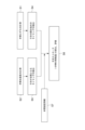
- FIG. 4 is a functional block diagram of controller 110 according to some embodiments.
- a control device 110 includes a first detection unit 121, a second detection unit 122, a calculation unit 123, and an evaluation unit 124 as functional blocks. These functional blocks are implemented by the processor 111 executing programs stored in the memory 113 .
- FIG. 5 is a flowchart showing the procedure of processing in the steam valve measurement method according to the first embodiment. Note that the processing shown in FIG. 5 is executed by the processor 111 executing a program stored in the memory 113 .
- the contact portion 621 of the child valve 62 and the valve seat surface 48a of the valve seat 48 are separated from the reference position of the valve stem 61. It is assumed that the position of the valve stem 61 is at the beginning of the opening of the child valve 62 .
- the timing at which the child valve 62 starts to open is detected from the strain measurement result of the valve stem 61 .
- the timing at which the child valve 62 is fully opened is detected from the measurement result of the acceleration of the valve stem 61 .
- the displacement gauge 105 measures the amount of movement of the valve stem 61 .
- the control device 110 starts measurement of valve stem strain by the strain sensor 103 (step S1) and measurement of valve stem acceleration by the acceleration sensor 101 (step S2).
- the controller 110 also starts measuring the distance to the displacement gauge target 105a by the displacement gauge 105, that is, the amount of movement of the valve stem 61 (step S3).
- FIG. 6 is a graph showing the measurement result of the valve stem strain by the strain sensor 103 and the measurement result of the valve stem acceleration by the acceleration sensor 101 when the movement amount of the valve stem 61 is taken on the horizontal axis.
- the second detection unit 122 of the control device 110 detects the opening start timing of the child valve 62 based on the measurement result of the valve stem strain by the displacement gauge 105 (step S4). Just before the child valve 62 starts to open, the child valve 62 tries to open against the pressure of the high-pressure steam acting on the child valve 62 , so a relatively large compressive force acts on the valve stem 61 . Therefore, a relatively large compressive strain is generated in the valve stem 61 .
- the first detection unit 121 of the control device 110 detects the timing when the child valve 62 is fully opened based on the measurement result of the valve stem acceleration by the acceleration sensor 101 (step S5).
- the valve stem inclined surface 619 of the valve stem 61 and the contact surface 711 of the main valve main body 71 abut as shown in FIG. 3B. Therefore, a relatively clear peak P1 appears on the graph line g2 representing the acceleration of the valve stem 61 in FIG.
- the child valve 62 is fully opened when this peak P1 appears.
- the calculation unit 123 of the control device 110 calculates the stroke amount (position) of the valve stem 61 corresponding to the point S1 on the graph line g1 representing the strain of the valve stem 61 in FIG. 6 and the graph representing the acceleration of the valve stem 61 in FIG.
- the difference from the stroke amount (position) of the valve stem 61 corresponding to the peak P1 on the line g2 is the movement amount of the valve stem from the reference position (the position where the child valve 62 starts to open) to the position where the child valve 62 is fully opened. (child valve stroke).
- FIG. 7 is an example showing how the child valve stroke (estimated child valve stroke) calculated as described above changes each time the steam turbine 10 is started. As shown in FIG. 7, the estimated valve stroke gradually increases as the steam turbine 10 is started up.
- FIG. 8 is a diagram showing the configuration of an apparatus for carrying out the steam valve measuring method according to the second embodiment.
- a steam valve measuring device 100 according to the second embodiment includes an acceleration sensor 101 , a displacement gauge 105 , and a control device 110 .
- the same components as those of the steam valve measuring device 100 according to the first embodiment are given the same reference numerals as those of the steam valve measuring device 100 according to the first embodiment, and detailed descriptions thereof are omitted. may be omitted.
- the contact portion 621 of the child valve 62 and the valve seat of the valve seat 48 are positioned at the reference position of the valve stem 61 .
- the position of the valve stem 61 is at the beginning of the opening of the child valve 62 where the surface 48a begins to separate.
- the opening timing of the child valve 62 is detected from the measurement result of the acceleration of the valve stem 61 instead of the measurement result of the strain of the valve stem 61 .
- the timing at which the child valve 62 is fully opened is detected from the measurement result of the acceleration of the valve stem 61, as in the first embodiment.
- the amount of movement of the valve stem 61 is measured by the displacement gauge 105, as in the first embodiment.
- FIG. 9 is a flowchart showing the procedure of processing in the steam valve measurement method according to the second embodiment. Note that the processing shown in FIG. 9 is executed by the processor 111 executing a program stored in the memory 113 .
- the control device 110 starts measuring the valve stem acceleration by the acceleration sensor 101 (step S2).
- the controller 110 also starts measuring the distance to the displacement gauge target 105a by the displacement gauge 105, that is, the amount of movement of the valve stem 61 (step S3).
- FIG. 10A is an enlarged view of area B in FIG. 2, showing the vicinity of the proximal end 61C of the valve stem 61 and the actuator crosshead 49 when the stop valve 45 is fully closed.
- FIG. 10B is an enlarged view of area B in FIG. 2, showing the vicinity of the base end 61C of the valve stem 61 and the actuator crosshead 49 immediately after the actuator 46B starts to drive after the stop valve 45 is fully closed. It is a diagram. As shown in FIGS.
- the first detection unit 121 of the control device 110 detects the timing when the child valve 62 is fully opened based on the measurement result of the valve stem acceleration by the acceleration sensor 101 (step S5).
- the calculation unit 123 of the control device 110 calculates the difference between the stroke amount (position) of the valve stem 61 corresponding to the peak P2 on the graph line g2 and the stroke amount (position) of the valve stem 61 corresponding to the peak P1 on the graph line g2. is calculated as the movement amount (child valve stroke) of the valve stem from the reference position (the position where the child valve 62 starts to open) to the position where the child valve 62 is fully opened (step S6).
- FIG. 11 is a diagram showing the configuration of an apparatus for implementing the steam valve measuring method according to the third embodiment.
- a steam valve measuring device 100 according to the third embodiment includes an acceleration sensor 101 , a strain sensor 103 , and a control device 110 .
- the same components as those of the steam valve measuring device 100 according to the first embodiment are given the same reference numerals as those of the steam valve measuring device 100 according to the first embodiment, and detailed descriptions thereof are omitted. may be omitted.
- the contact portion 621 of the child valve 62 and the valve seat of the valve seat 48 are set to the reference position of the valve stem 61 .
- the position of the valve stem 61 is at the beginning of the opening of the child valve 62 where the surface 48a begins to separate.
- the opening timing of the child valve 62 is detected from the strain measurement result of the valve stem 61 .
- the timing at which the child valve 62 is fully opened is detected from the measurement result of the acceleration of the valve stem 61, as in the first embodiment.
- the valve opening speed information (moving speed of the valve stem 61) obtained in advance and the elapsed time A movement amount of the valve stem 61 is calculated. That is, in the method for measuring the steam valve according to the third embodiment, for example, the moving speed of the valve stem 61 obtained by actual measurement in advance, or the speed estimated from the specifications of the actuator 46B and the amount of pressure oil supplied to the actuator 46B.
- the amount of movement of the valve rod 61 is calculated based on previously obtained valve opening speed information, such as the moving speed of the valve rod 61 obtained in advance based on the driving speed of the actuator 46B.
- FIG. 12 is a flowchart showing the procedure of processing in the steam valve measurement method according to the third embodiment. Note that the processing shown in FIG. 12 is executed by the processor 111 executing a program stored in the memory 113 .
- the control device 110 starts measurement of valve stem strain by the strain sensor 103 (step S1) and measurement of valve stem acceleration by the acceleration sensor 101 (step S2). Further, the control device 110 reads the valve opening speed information stored in the memory 113, for example, and measures the elapsed time from the start of driving the actuator 46B (step S7).
- the second detection unit 122 of the control device 110 detects the opening start timing of the child valve 62 based on the measurement result of the valve stem strain by the displacement gauge 105 (step S4).
- the first detection unit 121 of the control device 110 detects the timing when the child valve 62 is fully opened based on the measurement result of the valve stem acceleration by the acceleration sensor 101 (step S5).
- the calculation unit 123 of the control device 110 calculates the stroke amount (position) of the valve stem 61 corresponding to the point S1 on the graph line g1 representing the strain of the valve stem 61 in FIG. It is calculated from the elapsed time from the start of driving of 46B to the detection of point S1 on graph line g1.
- the calculation unit 123 of the control device 110 calculates the stroke amount (position) of the valve stem 61 corresponding to the peak P1 on the graph line g2 representing the acceleration of the valve stem 61 in FIG. It is calculated from the elapsed time from the start of driving of 46B to the detection of peak P1 on graph line g2.
- the calculation unit 123 of the control device 110 calculates the stroke amount (position) of the valve stem 61 corresponding to the point S1 on the graph line g1 and the stroke amount (position) of the valve stem 61 corresponding to the peak P1 on the graph line g2. is calculated as the movement amount (child valve stroke) of the valve stem from the reference position (the position where the child valve 62 starts to open) to the position where the child valve 62 is fully opened (step S6).
- FIG. 13 is a diagram showing the configuration of an apparatus for carrying out the steam valve measuring method according to the fourth embodiment.
- a steam valve measuring device 100 according to the first embodiment includes an acceleration sensor 101 , a strain sensor 103 , a pressure sensor 107 , and a control device 110 .
- the pressure sensor 107 is a pressure sensor for measuring the pressure of pressure oil (actuator oil pressure) supplied to the actuator 46B.
- pressure oil actuator oil pressure
- the contact portion 621 of the child valve 62 and the valve seat surface 48a of the valve seat 48 begin to separate from the reference position of the valve stem 61.
- the position of the valve stem 61 at the start of opening of the valve 62 is assumed.
- the timing at which the child valve 62 starts to open is detected from the pressure of pressure oil supplied to the actuator 46B (actuator oil pressure), not from the strain measurement result of the valve stem 61. .
- the timing at which the child valve 62 is fully opened is detected from the measurement result of the acceleration of the valve stem 61 .
- the displacement gauge 105 measures the amount of movement of the valve stem 61 .
- FIG. 14 is a flow chart showing the procedure of processing in the steam valve measuring method according to the fourth embodiment. Note that the processing shown in FIG. 14 is executed by the processor 111 executing a program stored in the memory 113 .
- the control device 110 starts measuring the actuator hydraulic pressure with the pressure sensor 107 (step S8), and starts measuring the valve stem acceleration with the acceleration sensor 101 (step S2).
- the controller 110 also starts measuring the distance to the displacement gauge target 105a by the displacement gauge 105, that is, the amount of movement of the valve stem 61 (step S3).
- the second detection unit 122 of the control device 110 detects the opening start timing of the child valve 62 based on the measurement result of the actuator hydraulic pressure by the pressure sensor 107 (step S4). Just before the child valve 62 begins to open, the actuator hydraulic pressure rises because the child valve 62 tries to open against the pressure of the high-pressure steam acting on the child valve 62 .
- the actuator hydraulic pressure rises because the child valve 62 tries to open against the pressure of the high-pressure steam acting on the child valve 62 .
- high-pressure steam flows into the inlet 71Ba of the through hole 71B from the gap between the valve seat surface 71a and the contact portion 621, and the steam flow path 52 flows from the outlet 71Bb of the through hole 71B. , the pressure of the steam acting on the child valve 62 is reduced. Therefore, the actuator hydraulic pressure gradually decreases.
- the actuator hydraulic pressure shows pressure changes similar to the graph line g1 representing the strain of the valve stem 61 in FIG. Therefore, by using the measurement result of the actuator hydraulic pressure, the child valve 62 starts to open at the point where the actuator hydraulic pressure suddenly starts to decrease, like the point S1 on the graph line g1 representing the strain of the valve stem 61 in FIG. be.
- the first detection unit 121 of the control device 110 detects the timing when the child valve 62 is fully opened based on the measurement result of the valve stem acceleration by the acceleration sensor 101 (step S5).
- the calculation unit 123 of the control device 110 calculates the stroke amount (position) of the valve stem 61 corresponding to the point at which the actuator hydraulic pressure suddenly begins to decrease, and the peak on the graph line g2 representing the acceleration of the valve stem 61 in FIG.
- the difference from the stroke amount (position) of the valve stem 61 corresponding to P1 is the movement amount of the valve stem (child valve stroke ) (step S6).
- the evaluation unit 124 of the control device 110 evaluates the wear amount of the steam valve 14 from the estimated valve stroke as described above (step S6).
- the method of measuring a steam valve is to open the child valve 62 by driving the valve stem 61 with the actuator 46B from the fully closed state of the parent valve 64 and the child valve 62.
- Step S2 of measuring the acceleration of the valve stem 61
- Step S5 of detecting the timing at which the child valve 62 is fully opened based on the measured acceleration of the valve stem 61
- a step S6 of calculating the amount of movement of the valve stem by detecting the acceleration of the valve stem 61, the child valve 62 is fully opened without disassembling the steam valve 14 while the steam turbine 10 continues to operate. Timing can be detected.
- the timing at which the child valve 62 is fully opened can be detected with high accuracy. This improves the accuracy of calculation of the amount of movement of the valve stem 61 from the reference position to the position where the child valve 62 is fully opened, and improves the accuracy of measuring wear of the steam valve 14 .
- a steam valve measuring device 100 includes an acceleration sensor 101 for measuring the acceleration of a valve stem 61, and a child valve 62 that is fully opened based on the acceleration of the valve stem 61 measured by the acceleration sensor 101. and a calculation unit 123 for calculating the amount of movement of the valve stem 61 from the reference position to the position where the child valve 62 is fully opened.
- the child valve 62 can be fully opened without disassembling the steam valve 14 while the operation of the steam turbine 10 is continued. timing can be detected.
- the timing at which the child valve 62 is fully opened can be detected with high accuracy. This improves the accuracy of calculation of the amount of movement of the valve stem 61 from the reference position to the position where the child valve 62 is fully opened, and improves the accuracy of measuring wear of the steam valve 14 .
- the reference position is the position of the valve stem 61 when the child valve 62 begins to open.
- the steam valve measuring device 100 includes a second detection unit 122 that detects the timing at which the child valve 62 starts to open.
- the calculation unit 123 calculates the amount of movement of the valve stem 61 from the reference position to the position where the child valve 62 is fully opened, using the timing at which the child valve 62 starts to open detected by the second detection unit 122 as a reference position.
- the reference position to be referred to when calculating the amount of movement of the valve stem 61 from the reference position to the position where the child valve 62 is fully opened can be used. Since it can be identified relatively accurately, the accuracy of the amount of movement of the valve stem 61 from the calculated reference position to the position where the child valve 62 is fully opened is improved.
- Step S1 of measuring the strain of the valve stem 61 and Step S4 of detecting the timing at which the child valve 62 starts to open based on the measured strain of the valve stem 61. Since a relatively large force is required to open the child valve 62, the strain of the valve stem 61 when opening the child valve 62 can be measured relatively easily. Therefore, it becomes easy to detect the timing when the child valve 62 starts to open. Further, by measuring the strain of the valve stem 61 when the child valve 62 is opened, the detection accuracy of the timing when the child valve 62 starts to open can be improved.
- the method for measuring the steam valve shown in FIG. 9 includes step S4 of detecting the timing at which the child valve 62 starts to open based on the measured acceleration of the valve stem 61 .
- step S4 of detecting the timing at which the child valve 62 starts to open based on the measured acceleration of the valve stem 61 .
- the device configuration for detection can be simplified.
- the method for measuring the steam valve shown in FIG. 9 compared to the case of detecting the timing at which the child valve 62 starts to open based on the strain of the valve stem 61, for example, it is possible to omit the trouble of measuring the strain.
- the pressure of the pressurized oil supplied to the actuator 46B when the valve stem is driven by the actuator 46B to open the child valve 62 from the fully closed state of the parent valve 64 and the child valve 62 is and a step S4 of detecting the timing at which the child valve 62 starts to open based on the measured pressure of the pressurized oil.
- measuring the pressure of the pressure oil supplied to the actuator 46B, which is a hydraulic actuator is simple with a comparator. Timing can be detected.
- the labor of measuring the strain can be omitted compared to the case of detecting the timing at which the child valve 62 starts to open based on the strain of the valve stem 61, for example.
- the reference position may not be the position of the valve stem 61 when the child valve 62 starts to open. It may be the position of the valve stem 61 in the closed state. This facilitates setting and detection of the reference position.
- step S6 of calculating the amount of movement of the valve stem 61 the position of the valve stem 61 detected by the displacement gauge 105 is The amount of movement of the valve stem 61 from the reference position to the position where the child valve 62 is fully opened is calculated based on the change in .
- the detection accuracy of the position of the valve stem 61 is relatively high, so the calculation accuracy of the amount of movement of the valve stem 61 from the reference position to the position where the child valve 62 is fully opened can be improved.
- step S6 for calculating the movement amount of the valve stem 61 the child valve 62 is moved from the reference position based on the known movement speed information (valve opening speed information) of the valve stem 61. is calculated the amount of movement of the valve stem 61 to the position where is fully open. As a result, the displacement gauge 105 for detecting the position of the valve stem 61 can be omitted.
- each step shown in FIGS. It is executed by However, in some embodiments of the steam valve gauging method, at least some of the steps shown in FIGS. 5, 9, 12, and 14 may be performed by an operator.
- a steam valve measurement method includes a steam flow path 52 through which steam flows, and a valve body 41 having a valve seat 48 provided in the middle of the steam flow path 52 and having an opening.
- valve stem 61 extending in the axial direction Z along which the axes O1 and O2 extend and capable of advancing and retracting in the axial direction Z
- a child valve 62 provided at the tip of the valve stem 61 of the tip portion 61A of the valve stem 61, and a penetrating portion 71A into which a portion of the distal end portion 61A of the valve stem 61 located closer to the base end of the valve stem 61 than the distal end is inserted, and the valve seat 48 abuts on the steam flow path 52.
- a method for measuring a steam valve 14 comprising a stop valve 45 having a parent valve 64 formed with a through hole 71B through which steam flows when the child valve 62 is closed and an actuator 46B for driving the valve stem 61 be.
- the steam valve measurement method is based on the acceleration of the valve stem 61 when the valve stem 61 is driven by the actuator 46B from the fully closed state of the parent valve 64 and the child valve 62 to open the child valve 62.
- step S2 of measuring step S5 of detecting the timing at which the child valve 62 is fully opened based on the measured acceleration of the valve stem 61, movement of the valve stem 61 from the reference position to the position at which the child valve 62 is fully opened and a step S6 of calculating the quantity.
- the timing at which the child valve 62 is fully opened can be detected with high accuracy. This improves the accuracy of calculation of the amount of movement of the valve stem 61 from the reference position to the position where the child valve 62 is fully opened, and improves the accuracy of measuring wear of the steam valve 14 .
- the reference position may be the position of the valve stem 61 when the child valve 62 begins to open.
- the method (2) above by setting the reference position to the position of the valve stem 61 when the child valve 62 starts to open, the amount of movement of the valve stem 61 from the reference position to the position where the child valve 62 is fully opened is Since the reference position referred to in the calculation of can be specified relatively accurately, the accuracy of the amount of movement of the valve stem 61 from the calculated reference position to the position where the sub-valve 62 is fully opened is improved.
- valve stem 61 is opened when the valve stem 61 is driven by the actuator 46B from the fully closed state of the parent valve 64 and the child valve 62 to open the child valve 62. and a step S4 of detecting the timing at which the child valve 62 starts to open based on the measured strain of the valve stem 61 .
- the strain of the valve stem 61 when opening the child valve 62 can be measured relatively easily. Therefore, it becomes easy to detect the timing when the child valve 62 starts to open. Further, by measuring the strain of the valve stem 61 when the child valve 62 is opened, the detection accuracy of the timing when the child valve 62 starts to open can be improved.
- the method (2) may include a step S4 of detecting the timing at which the child valve 62 begins to open based on the measured acceleration of the valve stem 61 .
- the above method (4) it is possible to detect the timing when the child valve 62 starts to open and the timing when the child valve 62 fully opens, for example, based on the measurement result of the same acceleration sensor 101, so these timings are detected.
- the device configuration for this can be simplified.
- the method (4) above compared with the case of detecting the timing at which the child valve 62 starts to open based on the strain of the valve stem 61, for example, it is possible to omit the trouble of measuring the strain.
- the actuator 46B may be a hydraulic actuator.
- a step S4 of detecting the timing at which the child valve 62 starts to open based on the measured pressure of the pressurized oil may also be provided.
- measuring the pressure of the pressure oil supplied to the hydraulic actuator (actuator 46B) is simple with a comparator. detectable. Moreover, according to the method (5) above, compared with the case of detecting the timing at which the child valve 62 starts to open based on the strain of the valve stem 61, for example, it is possible to omit the trouble of measuring the strain.
- the reference position may be the position of the valve stem 61 when the parent valve 64 and child valve 62 are fully closed.
- step S6 of calculating the amount of movement of the valve stem 61 the position of the valve stem 61 detected by the displacement gauge 105 is It is preferable to calculate the amount of movement of the valve stem 61 from the reference position to the position where the child valve 62 is fully opened based on the change.
- the detection accuracy of the position of the valve stem 61 is relatively high, so the calculation accuracy of the movement amount of the valve stem 61 from the reference position to the position where the child valve 62 is fully opened can be improved. .
- step S8 of calculating the amount of movement of the valve stem 61 information on the known movement speed of the valve stem 61 (valve The amount of movement of the valve stem 61 from the reference position to the position where the child valve 62 is fully opened may be calculated based on the opening speed information).
- the displacement gauge 105 for detecting the position of the valve stem 61 can be omitted.
- a steam valve measuring device 100 includes a steam flow path 52 through which steam flows, and a valve body having a valve seat 48 provided in the middle of the steam flow path 52 and having an opening.
- a valve stem 61 extending in the axial direction Z along which the axes O1 and O2 extend and capable of advancing and retracting in the axial direction Z, and a child valve 62 provided at the tip of the valve stem 61 of the tip portion 61A of the valve stem 61.
- a through portion 71A into which a portion of the distal end portion 61A of the valve stem 61 located closer to the proximal end of the valve stem 61 than the distal end is inserted.
- a measuring device for a steam valve 14, comprising a stop valve 45 having a parent valve 64 formed with a through hole 71B through which steam flows when the child valve 62 is opened, and an actuator 46B for driving the valve stem 61.
- a steam valve measuring device 100 includes an acceleration sensor 101 for measuring the acceleration of a valve stem 61 and a child valve 62 based on the acceleration of the valve stem 61 measured by the acceleration sensor 101. It includes a first detection unit 121 that detects the timing of full opening, and a calculation unit 123 that calculates the amount of movement of the valve stem 61 from the reference position to the position where the child valve 62 is fully opened.
- the configuration (9) above by measuring the acceleration of the valve stem 61, it is possible to detect the timing at which the child valve 62 is fully opened without disassembling the steam valve 14 while the operation of the steam turbine 10 is continued. . Further, according to the configuration (9) above, by measuring the acceleration of the valve stem 61, it is possible to accurately detect the timing at which the child valve 62 is fully opened. This improves the accuracy of calculation of the amount of movement of the valve stem 61 from the reference position to the position where the child valve 62 is fully opened, and improves the accuracy of measuring wear of the steam valve 14 .
- the second detection section 122 may be provided to detect the timing at which the child valve 62 starts to open.
- the calculation unit 123 may calculate the amount of movement of the valve stem 61 from the reference position to the position where the child valve 62 is fully opened, using the timing at which the child valve 62 begins to open detected by the second detection unit 122 as a reference position.
- the reference position to the position of the valve stem 61 when the child valve 62 starts to open
- the amount of movement of the valve stem 61 from the reference position to the position where the child valve 62 is fully opened is Since the reference position referred to in the calculation of can be specified relatively accurately, the accuracy of the amount of movement of the valve stem 61 from the calculated reference position to the position where the sub-valve 62 is fully opened is improved.
Landscapes
- Engineering & Computer Science (AREA)
- General Engineering & Computer Science (AREA)
- Mechanical Engineering (AREA)
- Chemical & Material Sciences (AREA)
- Combustion & Propulsion (AREA)
- Physics & Mathematics (AREA)
- Fluid Mechanics (AREA)
- Control Of Turbines (AREA)
- Lift Valve (AREA)
- Indication Of The Valve Opening Or Closing Status (AREA)
Priority Applications (5)
| Application Number | Priority Date | Filing Date | Title |
|---|---|---|---|
| DE112022002448.8T DE112022002448B4 (de) | 2022-02-01 | 2022-12-13 | Messverfahren für dampfventil und messvorrichtung für dampfventil |
| US18/293,080 US12287045B2 (en) | 2022-02-01 | 2022-12-13 | Measurement method for steam valve and measurement device for steam valve |
| KR1020237034520A KR102835946B1 (ko) | 2022-02-01 | 2022-12-13 | 증기 밸브의 계측 방법 및 증기 밸브의 계측 장치 |
| JP2023540673A JP7442021B2 (ja) | 2022-02-01 | 2022-12-13 | 蒸気弁の計測方法及び蒸気弁の計測装置 |
| CN202280029218.2A CN117178134A (zh) | 2022-02-01 | 2022-12-13 | 蒸汽阀的计测方法及蒸汽阀的计测装置 |
Applications Claiming Priority (2)
| Application Number | Priority Date | Filing Date | Title |
|---|---|---|---|
| JP2022014366 | 2022-02-01 | ||
| JP2022-014366 | 2022-02-01 |
Publications (1)
| Publication Number | Publication Date |
|---|---|
| WO2023149090A1 true WO2023149090A1 (ja) | 2023-08-10 |
Family
ID=87552217
Family Applications (1)
| Application Number | Title | Priority Date | Filing Date |
|---|---|---|---|
| PCT/JP2022/045769 Ceased WO2023149090A1 (ja) | 2022-02-01 | 2022-12-13 | 蒸気弁の計測方法及び蒸気弁の計測装置 |
Country Status (6)
| Country | Link |
|---|---|
| US (1) | US12287045B2 (https=) |
| JP (1) | JP7442021B2 (https=) |
| KR (1) | KR102835946B1 (https=) |
| CN (1) | CN117178134A (https=) |
| DE (1) | DE112022002448B4 (https=) |
| WO (1) | WO2023149090A1 (https=) |
Citations (4)
| Publication number | Priority date | Publication date | Assignee | Title |
|---|---|---|---|---|
| JPS5825502A (ja) * | 1981-08-07 | 1983-02-15 | Hitachi Ltd | タ−ビン弁診断装置 |
| JP2016205584A (ja) * | 2015-04-27 | 2016-12-08 | 株式会社テージーケー | 電動弁装置および電動弁制御装置 |
| JP2017160890A (ja) * | 2016-03-11 | 2017-09-14 | 株式会社東芝 | 蒸気タービン弁駆動装置 |
| WO2020138307A1 (ja) * | 2018-12-28 | 2020-07-02 | 三菱日立パワーシステムズ株式会社 | 蒸気弁、及び発電システム |
Family Cites Families (15)
| Publication number | Priority date | Publication date | Assignee | Title |
|---|---|---|---|---|
| US4523286A (en) | 1981-08-07 | 1985-06-11 | Hitachi, Ltd. | Apparatus for making diagnosis of valve device in turbine system |
| JPH078504U (ja) * | 1993-07-02 | 1995-02-07 | 三菱重工業株式会社 | 主蒸気止め弁 |
| JP4010374B2 (ja) | 1995-03-24 | 2007-11-21 | 日本ギア工業株式会社 | 弁装置の負荷検出装置 |
| JPH0988911A (ja) | 1995-09-26 | 1997-03-31 | Ishikawajima Harima Heavy Ind Co Ltd | 弁の弁体衝突検出方法 |
| US5771926A (en) * | 1995-11-03 | 1998-06-30 | Medal; George L. | Double seat value with switch monitoring design |
| NL2002209C2 (en) * | 2008-11-14 | 2010-05-17 | Asco Controls Bv | Solenoid valve with sensor for determining stroke, velocities and/or accelerations of a moveable core of the valve as indication of failure modus and health status. |
| CN102364173B (zh) * | 2011-11-21 | 2012-12-05 | 黄建斌 | 变轨调节阀 |
| JP2014070513A (ja) | 2012-09-28 | 2014-04-21 | Hitachi Ltd | 蒸気タービン用蒸気弁 |
| WO2015021163A2 (en) * | 2013-08-09 | 2015-02-12 | Sentimetal Journey Llc | Linear Valve Actuator System and Method for Controlling Valve Operation |
| JP6382556B2 (ja) * | 2014-04-08 | 2018-08-29 | 株式会社東芝 | 蒸気弁 |
| US10719089B2 (en) * | 2017-05-18 | 2020-07-21 | Fisher Controls International Llc | Apparatus and methods to characterize fluid control valves |
| CN109973671B (zh) * | 2019-04-04 | 2024-04-12 | 航空工业(新乡)计测科技有限公司 | 子母阀芯式精准流量调节阀 |
| CN110307389B (zh) * | 2019-06-28 | 2020-12-18 | 国网浙江省电力有限公司电力科学研究院 | 一种基于状态反馈的汽轮机液动阀门故障诊断方法 |
| JP7459692B2 (ja) | 2020-07-06 | 2024-04-02 | Toppanホールディングス株式会社 | 衛生マスク及び衛生マスク用銅板 |
| CN117460908A (zh) * | 2021-06-11 | 2024-01-26 | 基伊埃图亨哈根有限公司 | 双座阀 |
-
2022
- 2022-12-13 KR KR1020237034520A patent/KR102835946B1/ko active Active
- 2022-12-13 WO PCT/JP2022/045769 patent/WO2023149090A1/ja not_active Ceased
- 2022-12-13 CN CN202280029218.2A patent/CN117178134A/zh active Pending
- 2022-12-13 JP JP2023540673A patent/JP7442021B2/ja active Active
- 2022-12-13 DE DE112022002448.8T patent/DE112022002448B4/de active Active
- 2022-12-13 US US18/293,080 patent/US12287045B2/en active Active
Patent Citations (4)
| Publication number | Priority date | Publication date | Assignee | Title |
|---|---|---|---|---|
| JPS5825502A (ja) * | 1981-08-07 | 1983-02-15 | Hitachi Ltd | タ−ビン弁診断装置 |
| JP2016205584A (ja) * | 2015-04-27 | 2016-12-08 | 株式会社テージーケー | 電動弁装置および電動弁制御装置 |
| JP2017160890A (ja) * | 2016-03-11 | 2017-09-14 | 株式会社東芝 | 蒸気タービン弁駆動装置 |
| WO2020138307A1 (ja) * | 2018-12-28 | 2020-07-02 | 三菱日立パワーシステムズ株式会社 | 蒸気弁、及び発電システム |
Also Published As
| Publication number | Publication date |
|---|---|
| JP7442021B2 (ja) | 2024-03-01 |
| JPWO2023149090A1 (https=) | 2023-08-10 |
| US20240344631A1 (en) | 2024-10-17 |
| DE112022002448B4 (de) | 2025-07-03 |
| CN117178134A (zh) | 2023-12-05 |
| KR20230157394A (ko) | 2023-11-16 |
| US12287045B2 (en) | 2025-04-29 |
| DE112022002448T5 (de) | 2024-04-18 |
| KR102835946B1 (ko) | 2025-07-17 |
Similar Documents
| Publication | Publication Date | Title |
|---|---|---|
| JP5548196B2 (ja) | 自動化されたバルブテスト装置 | |
| US11300228B2 (en) | Partial stroke tests for shutdown valves | |
| KR100777254B1 (ko) | 모터식 포핏밸브 및 모터식 포핏밸브를 이용한 내연기관의이지알 장치 | |
| US20180156063A1 (en) | Arrangement, turbo engine and method for the recognition of a shaft breakage of a shaft | |
| CN105317552B (zh) | 内燃机系统 | |
| EP1691063A3 (en) | Stuck-open failure detection system for gas-fuel injection valve | |
| CN102333944A (zh) | 预燃室式发动机控制方法 | |
| WO2023149090A1 (ja) | 蒸気弁の計測方法及び蒸気弁の計測装置 | |
| CN101561048A (zh) | 高低压导阀 | |
| US12435814B2 (en) | Spring fracture detection in a preloaded actuator of a control valve | |
| US10519964B2 (en) | System and method for turbomachinery rotor and blade prognostics and diagnostics | |
| JP7387738B2 (ja) | シリンダの制御方法 | |
| TWI659812B (zh) | 燃燒動力驅動的安置設備、其操作方法及具有執行該方法的程式指令的電腦程式產品 | |
| RU2016102209A (ru) | Способ управления газотурбинным двигателем с форсажной камерой сгорания и система для его осуществления | |
| CN112005037A (zh) | 用于监测调节阀功能的方法、用于执行这种方法的装置以及具有这种装置的调节阀 | |
| JP6737669B2 (ja) | 真空圧力制御システム及び真空圧力制御用コントローラ | |
| JP2008503686A (ja) | 可変弁制御を有する内燃機関における少なくとも1つの弁リフト位置の検出方法 | |
| JP2021060299A (ja) | 不調判定装置および方法 | |
| JP5653533B2 (ja) | 制御装置 | |
| RU2009107968A (ru) | Способ управления газотурбинным двигателем | |
| RU2011139332A (ru) | Способ испытаний управляющего сопла с эластичным опорным шарниром и приводом с определением угла поворота подвижной части сопла | |
| Conti et al. | Vibration signals for condition based maintenance of hydraulic valves | |
| RU2012102673A (ru) | Устройство и способ позиционирования оборудования с изменяемой геометрией для турбомашины с использованием гидроцилиндра с относительным измерением | |
| WO2022196552A1 (ja) | ガスタービン用燃焼器の異常検知システム、ガスタービン用の燃焼器及びガスタービン並びにガスタービン用燃焼器の異常検知方法 | |
| JP7784879B2 (ja) | 圧縮機用リングバルブの試験方法、及び圧縮機用リングバルブの試験装置 |
Legal Events
| Date | Code | Title | Description |
|---|---|---|---|
| WWE | Wipo information: entry into national phase |
Ref document number: 2023540673 Country of ref document: JP |
|
| 121 | Ep: the epo has been informed by wipo that ep was designated in this application |
Ref document number: 22924994 Country of ref document: EP Kind code of ref document: A1 |
|
| ENP | Entry into the national phase |
Ref document number: 20237034520 Country of ref document: KR Kind code of ref document: A |
|
| WWE | Wipo information: entry into national phase |
Ref document number: 1020237034520 Country of ref document: KR |
|
| WWE | Wipo information: entry into national phase |
Ref document number: 202317081102 Country of ref document: IN |
|
| WWE | Wipo information: entry into national phase |
Ref document number: 112022002448 Country of ref document: DE |
|
| 122 | Ep: pct application non-entry in european phase |
Ref document number: 22924994 Country of ref document: EP Kind code of ref document: A1 |
|
| WWG | Wipo information: grant in national office |
Ref document number: 18293080 Country of ref document: US |
|
| WWG | Wipo information: grant in national office |
Ref document number: 112022002448 Country of ref document: DE |