WO2023145841A1 - カーボンナノチューブ集合体の製造方法及び製造装置 - Google Patents
カーボンナノチューブ集合体の製造方法及び製造装置 Download PDFInfo
- Publication number
- WO2023145841A1 WO2023145841A1 PCT/JP2023/002523 JP2023002523W WO2023145841A1 WO 2023145841 A1 WO2023145841 A1 WO 2023145841A1 JP 2023002523 W JP2023002523 W JP 2023002523W WO 2023145841 A1 WO2023145841 A1 WO 2023145841A1
- Authority
- WO
- WIPO (PCT)
- Prior art keywords
- furnace
- gas
- catalyst
- formation
- growth
- Prior art date
- Legal status (The legal status is an assumption and is not a legal conclusion. Google has not performed a legal analysis and makes no representation as to the accuracy of the status listed.)
- Ceased
Links
Images
Classifications
-
- C—CHEMISTRY; METALLURGY
- C01—INORGANIC CHEMISTRY
- C01B—NON-METALLIC ELEMENTS; COMPOUNDS THEREOF; METALLOIDS OR COMPOUNDS THEREOF NOT COVERED BY SUBCLASS C01C
- C01B32/00—Carbon; Compounds thereof
- C01B32/15—Nano-sized carbon materials
- C01B32/158—Carbon nanotubes
- C01B32/16—Preparation
- C01B32/164—Preparation involving continuous processes
Definitions
- the present invention relates to a method and apparatus for manufacturing carbon nanotube aggregates.
- nanocarbon materials such as carbon nanotubes (hereinafter sometimes referred to as “CNT”) have attracted attention as materials with excellent electrical conductivity, thermal conductivity and mechanical properties. While it has been recognized that nanocarbon materials can offer superior properties, they have generally been more expensive than other materials due to their high manufacturing costs.
- CNT carbon nanotubes
- Patent Document 1 when manufacturing carbon nanotube aggregates, a formation step and a growth step are separately performed in this order, and in these steps, a substrate having a catalyst on its surface is conveyed by screw rotation. Therefore, a manufacturing method for efficiently producing a high-quality CNT aggregate has been proposed.
- Patent Document 2 a catalytic reaction device for thermally decomposing a hydrocarbon-containing compound by a catalytic reaction to generate ultrafine carbon together with hydrogen, which is equipped with a reaction tube having a rotary conveying and stirring means. disclosed.
- an object of the present invention is to provide a method and apparatus for producing a CNT aggregate that can further improve the production efficiency and carbon conversion efficiency when producing a carbon nanotube aggregate.
- the present inventors have conducted intensive studies with the aim of solving the above problems. As a result, the present inventors found that when producing a CNT aggregate using a substrate having a catalyst on its surface, in at least one of the formation process and the growth process, when the substrate is transported using a blade member, Furthermore, by repeating the above operation over a plurality of cycles, with regular forward and reverse rotation of the blade member as one cycle operation, the production efficiency and carbon conversion efficiency in manufacturing the CNT aggregate can be further increased. The present inventors have newly discovered that and completed the present invention.
- an object of the present invention is to advantageously solve the above problems.
- the blade member is configured to convey the base material in the conveying direction when rotated in the forward direction, and to move the base material in the direction opposite to the conveying direction when rotated in the reverse direction. and the total number of forward rotations in one cycle is greater than the total number of reverse rotations. According to such a manufacturing method, it is possible to increase the production efficiency and the carbon conversion efficiency when manufacturing the CNT aggregate.
- the rotational speed of the blade member is 1 rpm or more. According to such a production method, it is possible to further improve the production efficiency and carbon conversion efficiency when producing a CNT aggregate.
- the base material and the reducing gas are brought into contact with each other in a state of cocurrent flow and countercurrent flow. and, in the growth step, the source gas is supplied such that the base material and the source gas are in contact with each other in cocurrent and countercurrent states. It is preferable to implement at least one of According to such a production method, it is possible to further improve the production efficiency and carbon conversion efficiency when producing a CNT aggregate.
- a formation furnace for realizing the formation step a growth furnace for realizing the growth step, and an interior of the formation furnace
- a connecting portion that spatially connects a space and an in-furnace space of the growth furnace, and preventing mutual mixing of gases between the in-furnace space of the formation furnace and the in-furnace space of the growth furnace.
- a gas contamination prevention device that prevents the gas environment in each of the steps from being mixed with each other while continuously conveying the base material by the blade member, and the formation step and the It is preferable to perform the growth step. According to such a manufacturing method, it is possible to further improve the production efficiency and quality when manufacturing a CNT aggregate.
- the reducing gas is supplied from the lower side of the formation furnace to the base material, or and supplying the raw material gas to the base material from the lower side of the growth furnace in the growing step. According to such a production method, it is possible to further improve the production efficiency and carbon conversion efficiency when producing a CNT aggregate.
- the source gas environment in the growth step is a high carbon concentration environment and contains a catalyst activating substance. According to such a production method, it is possible to further improve the production efficiency and carbon conversion efficiency when producing a CNT aggregate.
- the source gas environment contains ethylene and carbon dioxide as a catalyst activation substance. According to such a production method, it is possible to further improve the production efficiency and carbon conversion efficiency when producing a CNT aggregate.
- the base material is particles having an apparent density of 2.0 g/cm 3 or more. According to such a production method, it is possible to further improve the production efficiency and carbon conversion efficiency when producing a CNT aggregate.
- the "apparent density" of the support means the mass per unit volume including the voids when the support is particles having voids (closed pores) inside. The "apparent density of the support” can be measured according to the pycnometer method.
- the substrate contains at least one element of Al, Si, and Zr.
- the production efficiency of CNT aggregates can be further improved.
- a catalyst layer forming step of supporting a catalyst on the base material, and separating the carbon nanotube aggregate from the base material and a separation and recovery step of separately recovering the substrate and the aggregate of carbon nanotubes, and a recycling step of making the substrate reusable by oxidizing and removing the carbon on the recovered substrate. is preferred.
- An apparatus for producing a carbon nanotube aggregate of the present invention is an apparatus for growing a carbon nanotube aggregate on a substrate having a catalyst on its surface, wherein the environment surrounding the catalyst is a reducing gas environment and the a formation furnace for realizing a formation step of heating at least one of the catalyst and the reducing gas; and an environment surrounding the catalyst is used as a source gas environment, and at least one of the catalyst and the source gas is heated to produce the carbon nanotubes.
- a stirring and conveying unit comprising a blade member for conveying in a direction, wherein the blade member conveys the base material layer in the conveying direction when rotating in the forward direction, and conveys the base material layer in the conveying direction when rotating in the reverse direction. It is configured to move the layer in a direction opposite to the transport direction, and the blade members included in at least one of the formation furnace and the growth furnace regularly rotate forward and backward. A plurality of cycles are repeated as one cycle, and the total number of forward rotations in one cycle can be set to be larger than the total number of reverse rotations.
- Such a production apparatus is excellent in production efficiency and carbon conversion efficiency when producing CNT aggregates.
- the blade member of the stirring and conveying unit can be set to a rotational speed of 1 rpm or more. According to such a manufacturing apparatus, it is possible to further improve the production efficiency and carbon conversion efficiency when manufacturing CNT aggregates.
- the apparatus for producing a carbon nanotube aggregate according to [12] or [13] above includes a connecting portion that spatially connects the furnace space of the formation furnace and the furnace space of the growth furnace; It is preferable to further include a gas contamination prevention device for preventing mutual mixing of gas between the furnace space of the formation furnace and the furnace space of the growth furnace. According to such a manufacturing apparatus, it is possible to further improve production efficiency and quality when manufacturing CNT aggregates.
- the formation furnace has a plurality of reducing gas injection ports arranged in a lower portion, and the reducing gas a reducing gas injection device configured to be able to supply the reducing gas to the base material layer from an injection port, or
- the growth furnace has a plurality of raw material gas injection ports arranged in a lower portion, and includes a raw material gas injection device configured to be able to supply the raw material gas from the raw material gas injection ports to the base material layer. is preferred. According to such a manufacturing apparatus, it is possible to further improve the production efficiency and carbon conversion efficiency when manufacturing CNT aggregates.
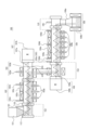
- FIG. 1 is a diagram for explaining a schematic configuration of a CNT aggregate manufacturing apparatus according to an example of the present invention
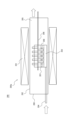
- FIG. FIG. 4 is a diagram for explaining a schematic configuration of an apparatus used for carrying out a verification example
- a CNT aggregate can be efficiently produced.
- Operations or components are described as being “upstream” operations or components, and further operations or components are described as being “downstream” operations or components.
- the method for producing a CNT aggregate of the present invention is a production method for growing a carbon nanotube aggregate on a substrate having a catalyst on its surface, wherein the environment surrounding the catalyst is a reducing gas environment, and A formation step of heating at least one of them, and a growing step of growing the aggregate of carbon nanotubes by heating at least one of the catalyst and the source gas while making the ambient environment of the catalyst a source gas environment.
- the blade members are regularly rotated forward and reverse when the substrate is conveyed along the conveying direction from the upstream side to the downstream side by the swirling motion of the blade members.
- the blade member is configured to convey the base material in the conveying direction when it rotates forward, and to move the base material in the direction opposite to the conveying direction when it rotates in the reverse direction. Further, the total number of forward rotations in one cycle of the turning motion of the blade member is more than the total number of reverse rotations.
- the method for producing a CNT aggregate of the present invention may further include a cooling step, a separation/recovery step, and/or a recycling step as steps performed after the growth step. Details of these steps will be described later.
- the substrate that constitutes the substrate having a catalyst on its surface which is used in the production method of the present invention, can be formed by supporting a catalyst on the substrate.
- the substrate is a member capable of supporting a catalyst for synthesizing CNTs on its surface, and is not particularly limited, and members made of any material can be used. Among them, it is preferable that the substrate is made of a ceramic material containing at least one element selected from Al, Si, and Zr. Furthermore, the substrate is preferably made of a metal oxide containing at least one of Al, Si, and Zr, and more preferably zirconium dioxide (ZrO 2 ). The shape of the substrate is preferably particulate with an aspect ratio of less than 5.
- the "aspect ratio" of the substrate particles can be obtained by calculating the values of (major axis/width perpendicular to the major axis) for a plurality of arbitrarily selected particles on a microscope image and obtaining the average value.
- the substrate particles preferably have an apparent density of 2.0 g/cm 3 or more, preferably 3.8 g/cm 3 or more, more preferably 5.8 g/cm 3 or more. 0 g/cm 3 or less is preferable. If the apparent density of the particulate base material is equal to or higher than the above lower limit, the resulting CNT aggregate can be elongated.
- the base material particles are excellent in handleability, and the production efficiency of the CNT aggregate can be further increased.
- the particle diameter of the substrate particles is preferably 0.05 mm or more, more preferably 0.3 mm or more, preferably 10 mm or less, more preferably 2 mm or less, and even more preferably 1 mm or less. If the particle size of the substrate particles is at least the above lower limit, the obtained CNT aggregate can be elongated. Moreover, if the particle size of the substrate particles is equal to or less than the above upper limit, the production efficiency of the CNT aggregate can be further enhanced.
- the "particle size" of the substrate particles means the volume average particle size D50.
- the volume average particle diameter D50 represents the particle diameter at which the cumulative volume calculated from the smaller diameter side is 50% in the particle size distribution (volume basis) measured by the laser diffraction method for the base particles.
- the catalyst supported on the substrate is not particularly limited, and includes catalyst components such as nickel (Ni), iron (Fe), cobalt (Co), and molybdenum (Mo).
- the catalyst component preferably contains at least one metal of nickel (Ni), iron (Fe), cobalt (Co), and molybdenum (Mo) from the viewpoint of further increasing the production efficiency of the CNT aggregate.
- an underlayer formed of a material such as aluminum oxide, titanium oxide, titanium nitride, or silicon oxide can be provided as an underlayer for supporting the catalyst on the substrate.
- the method of supporting the catalyst (or catalyst layer) on the substrate surface is not particularly limited, and any existing method can be adopted.
- a rotating drum type coating apparatus equipped with a substantially cylindrical rotating drum.
- the base material is placed in a substantially cylindrical rotating drum, and the rotating drum is rotated about an inclined axis or a horizontal axis, thereby stirring the base material particles while containing the above-described catalyst component.
- a solution containing components capable of constituting the underlayer and base particles are used prior to spraying and drying the catalyst solution.
- substrate particles having a base layer on the surface can be obtained.
- base particles having the base layer and the catalyst supported in this order on the surface can be obtained.
- base particles as the base material, as a method for preparing a base material having a catalyst on its surface, in addition to the above, for example, the base particles are caused to undergo centrifugal swirl flow and vertical floating flow, and the catalyst Methods include the step of spraying the solution.
- the reducing gas is a gas that has at least one effect of reducing the catalyst, promoting the atomization of the catalyst, and improving the activity of the catalyst.
- the reducing gas for example, hydrogen gas, ammonia, water vapor, and mixed gas thereof can be applied.
- a mixed gas in which hydrogen gas is mixed with an inert gas such as helium gas, argon gas, or nitrogen gas can also be used as the reducing gas.
- a reducing gas is generally used in the formation process, but may be used in the growth process as appropriate.
- Raw material gases used for the synthesis of CNT aggregates include, for example, hydrocarbons such as methane, ethane, ethylene, propane, butane, pentane, hexane, heptane propylene, and acetylene; lower alcohols such as methanol and ethanol; Mention may be made of low carbon number oxygenates such as carbon. Moreover, these can also be used in mixture of multiple types. Furthermore, this raw material gas may be diluted with an inert gas as described above.
- the source gas preferably contains ethylene.
- ethylene By heating ethylene in a predetermined temperature range (700° C. or higher and 900° C. or lower), the decomposition reaction of ethylene is promoted, and when the decomposition gas comes into contact with the catalyst, CNTs can grow at high speed.
- the thermal decomposition time is too long, the decomposition reaction of ethylene proceeds too much, causing deactivation of the catalyst and adhesion of carbon impurities to the CNT aggregates.
- the thermal decomposition time is preferably in the range of 0.5 seconds to 10 seconds with respect to the ethylene concentration in the range of 0.1 volume % to 40 volume %.
- the heated channel volume is the volume of the channel heated to a predetermined temperature T° C. through which the raw material gas passes before coming into contact with the catalyst, and the raw material gas flow rate is the flow rate at 0° C. and 1 atm.
- a catalyst activation material may be added in the CNT growth process. Addition of the catalyst activation material can further improve the production efficiency and quality of the CNT aggregate.
- the catalyst activating substance used here is generally a substance containing oxygen, and any substance that does not significantly damage the CNTs at the growth temperature may be used. low carbon oxygenates such as nitrogen, carbon monoxide and carbon dioxide; alcohols such as ethanol and methanol; ethers such as tetrahydrofuran; ketones such as acetone; aldehydes; A mixture of Among these, water, oxygen, carbon dioxide, carbon monoxide, or tetrahydrofuran is preferred, and carbon dioxide is more preferred.
- the CNTs In the growth step, by growing the CNTs in a high-carbon environment containing a catalyst-activating substance, the CNTs can be grown while maintaining catalytic activity for a long period of time.
- the production efficiency of CNT aggregates can be further improved.
- the source gas contains ethylene
- the presence of carbon dioxide as a catalyst activator can further improve the quality of the obtained CNT aggregates and the production efficiency of the CNT aggregates. The reason is presumed to be as follows. First, in the CNT synthesis reaction, it has been found that ethylene as a carbon source and carbon dioxide as a catalyst activator have relatively low activity, respectively.
- the amount of the catalyst activation material added in the growth step may be, for example, carbon dioxide, 0.5% by volume or more, preferably 4% by volume or more, and 5% by volume or more of the atmosphere in the growth step. is more preferable, and is usually 40% by volume or less.
- a high carbon concentration environment means an atmosphere in which 0.1% by volume or more of the atmosphere in the growth process (hereinafter also referred to as “source gas environment”) is source gas.
- the ratio of the raw material gas in the high carbon concentration environment can be, for example, 40% by volume or less.
- the ratio of the source gas in the high carbon concentration environment is preferably 4% by volume or more, more preferably 5% by volume or more, even more preferably 10% by volume or more, and preferably 30% by volume or less.
- the catalytic activity is significantly improved, so even in a high carbon concentration environment, the catalyst does not lose its activity and the CNT aggregate can be grown for a long time. In addition, the growth rate can be remarkably improved.
- the reaction temperature for growing the CNT aggregate is not particularly limited, and can be, for example, 400° C. or higher and 1100° C. or lower. Furthermore, when the source gas contains ethylene, the temperature is preferably 700°C or higher and 900°C or lower.
- the formation step is a step of making the environment around the catalyst supported on the base material a reducing gas environment and heating at least one of the catalyst and the reducing gas.
- a formation process is performed before the growth process mentioned later.
- reducing gas supply step As a result, the substrate having the catalyst on the surface and the reducing gas can be brought into contact with each other efficiently, and the catalyst supported on the surface of the substrate can be sufficiently activated in the formation process, thereby assembling CNTs. Body production efficiency and carbon conversion efficiency can be further increased.
- the base material may form a "base material layer" by stacking the base material on the lower part of the formation furnace by gravity or the like.
- the base material in the formation furnace is mechanically stirred and further conveyed by the blade members in the conveying direction from the upstream side to the downstream side (hereinafter also referred to as the “stirring and conveying step”. ) can be done.
- the supply of the reducing gas and the stirring and conveying of the base material can be performed at the same time or at a timing such that at least a part of them overlap.
- the reducing gas supplying process and the stirring and conveying process may all overlap. may be done.
- the blade member used in the agitating and conveying process may be a screw, paddle, or ribbon, or a combination thereof. At least one effect of reduction of the catalyst, promotion of fine particle formation in a state suitable for the growth of CNTs in the catalyst, and improvement in activity of the catalyst appears due to the agitating and conveying step by means of the blade member.
- the reducing gas may be supplied in any way in the furnace space of the formation furnace. It is preferable from the viewpoint of improving the contact efficiency between the reducing gas and the substrate that the reducing gas is supplied to the substrate layer from a plurality of gas injection ports arranged in the lower part of the furnace. At this time, it is preferable that the base material layer is mechanically stirred and/or conveyed in order to further improve the contact efficiency between the reducing gas and the base material. As a result, a reduction in the amount of reducing gas used and a shortening of the formation process can be expected, and the quality of the obtained CNT aggregates and the production efficiency of the CNT aggregates can be further improved.
- the reducing gas is continuously supplied so that the base material and the reducing gas come into contact with each other in the co-current and counter-current states in the furnace space of the formation furnace. .
- the substrate and the reducing gas conveyed by the blade members are brought into contact with each other in the states of co-current and counter-current, so that the substrate is reduced during the period in which the substrate is conveyed in the formation furnace. can efficiently secure the contact time between the and the reducing gas.
- the contact efficiency between the two can be improved by realizing both of the parallel flow and the counter flow instead of selecting either one of the parallel flow and the counter flow as the direction of contact between the two.
- by properly arranging the introduction position and the exhaust position of the reducing gas it is possible to optimize the retention time of the reducing gas in the manufacturing apparatus. This also makes it possible to further improve the quality of the obtained CNT aggregate and the production efficiency of the CNT aggregate.
- the temperature of the catalyst carrier or reducing gas atmosphere in the formation step is preferably 400°C or higher and 1100°C or lower.
- the execution time of the formation process may be 3 minutes or more and 120 minutes or less.
- the growth step is to use the surrounding environment of the catalyst, which has been brought into a state suitable for the production of CNT aggregates by the formation step described above, as the source gas environment, and to heat at least one of the catalyst and the source gas to form CNT aggregates. It is the process of growing the body.
- the base material is preferably supplied with a raw material gas from the lower side of the growth furnace in the growth furnace for performing the growth step (hereinafter also referred to as "raw material gas supply step"). .
- raw material gas supply step a raw material gas supply step
- the base material may form a "base material layer" by stacking the base material on the lower part of the furnace by gravity or the like in the growth furnace, as in the formation step.
- the substrate in the growth furnace is mechanically stirred using a blade member, and further, a stirring and conveying step can be performed in which the substrate is conveyed in the conveying direction from the upstream side to the downstream side. can. It is preferable that the raw material gas supplying step and the stirring and conveying step are performed at least partially overlapping each other.
- the source gas supplying step and the agitating and conveying step may all be performed in an overlapping manner.
- the uniformity of the gas to be supplied it is preferable that at least the raw material gas supply process overlaps with the stirring and conveying process, and it is more preferable that both the raw material gas supplying process and the stirring and conveying process overlap.
- the vane members used in the agitating and conveying process can be screws, paddles, or ribbons, or a combination of a plurality of them, as in the formation process.
- the raw material gas is injected into a plurality of gas injection ports arranged in the lower part of the growth furnace. is preferably supplied to the substrate layer from By supplying the raw material gas in this way, the raw material gas is supplied from the lower part of the base material layer, and the contact efficiency between the raw material gas and the base material can be improved. Furthermore, since the substrate layer can be mechanically stirred and/or transported, this also can further improve the contact efficiency between the source gas and the substrate.
- the supply amount of the raw material gas is such that the reciprocal of the average time for the gas to pass through the substrate layer formed in the lower part of the growth furnace is approximately equal to or greater than the CNT synthesis reaction rate coefficient per volume of the substrate layer. It is preferable to set By doing so, the CNT synthesis process becomes reaction rate-determining, so that it is possible to make the optimal growth time substantially the same when the reactor vessel is scaled up.
- the base material and the raw material gas conveyed by the blade members are brought into contact with each other in the state of co-current and counter-current in the furnace space of the growth furnace.
- the raw material gas is preferably supplied continuously.
- the quality of the obtained CNT aggregate and the production efficiency of the CNT aggregate can be further improved.
- by appropriately arranging the introduction position and the exhaust position of the raw material gas it is possible to optimize the residence time of the raw material gas in the manufacturing apparatus. This also makes it possible to further improve the quality of the obtained CNT aggregate and the production efficiency of the CNT aggregate.
- the blade member is rotated periodically to convey the base material along the conveying direction from the upstream side to the downstream side by the swirling motion of the blade member.
- the operation is repeated over a plurality of cycles, with the positive rotation and reverse rotation being one cycle of operation.
- the blade member is configured to convey the base material in the conveying direction when it rotates forward, and to move the base material in the direction opposite to the conveying direction when it rotates in the reverse direction.
- the base material is not simply conveyed unilaterally along the conveying direction, but is sometimes caused to flow backward.
- the production efficiency of the CNT aggregate can be enhanced, and the carbon conversion efficiency can be enhanced in the growth process.
- the total number of forward rotations in one cycle is greater than the total number of reverse rotations.
- the number of forward rotations in one cycle is greater than the number of reverse rotations by 0.5 rotations (that is, half a rotation) or more. Moreover, the difference between the total number of forward rotations and the total number of reverse rotations in one cycle is preferably 5 rotations or less.
- the rotational speed of the blade member is preferably 1 rpm or more, more preferably 2 rpm or more.
- the upper limit of the rotation speed is not particularly limited, but may be 10 rpm or less.
- a cooling step can be performed after the growing step.
- the CNT aggregate, catalyst, and substrate obtained in the growth step are cooled in an inert gas environment. Since the CNT aggregate, catalyst, and substrate after the growth process are in a high-temperature state, they tend to be easily oxidized when placed in an oxygen-existing environment. Therefore, it is preferable to cool the oriented aggregate of CNTs, the catalyst, and the substrate to 400° C. or less, more preferably 200° C. or less, in an inert gas environment.
- the separating and collecting step the aggregate of carbon nanotubes is separated from the substrate, and the aggregate of carbon nanotubes and the substrate are recovered separately.
- the recovery method is not particularly limited, and any known method can be adopted. Among them, a separation and recovery method using an external force and a fluid flow as a drag force of the external force (e.g., an air vortex formed by a centrifugal force and an air flow as a drag force of the centrifugal force) (e.g., International Publication No. 2019/ 188979) is preferably employed.
- the carbon on the recovered substrate is removed by oxidation to make the substrate reusable.
- the oxidation removal method is not particularly limited, and includes, for example, a method of heating the substrate while circulating air.
- the specific surface area of the CNT aggregate obtained by the production method of the present invention is determined by measuring the adsorption/desorption isotherm of liquid nitrogen at 77 K for CNTs that have not been subjected to an opening treatment, and using this adsorption/desorption isotherm, Brunauer, Emmett, Teller It is a value measured from the method of
- the specific surface area of a CNT aggregate can be measured using a BET specific surface area measuring device conforming to JIS Z8830.
- the specific surface area of the CNT obtained by the present invention is not particularly limited, but for example, it is preferably 600 m 2 /g or more, preferably 800 m 2 /g or more, and preferably 2600 m 2 /g or less. , 1400 m 2 /g or less. Furthermore, it is preferable that the specific surface area of the CNT aggregate subjected to the opening treatment is 1300 m 2 /g or more.
- the carbon nanotube aggregate production apparatus of the present invention is an apparatus for producing carbon nanotube aggregates by growing CNT aggregates on a base material having a catalyst on its surface.
- the apparatus for producing a carbon nanotube aggregate of the present invention includes a formation furnace that realizes a formation process of heating at least one of the catalyst and the reducing gas while making the environment around the catalyst a reducing gas environment, and an environment around the catalyst.
- a growth furnace that provides a source gas environment and heats at least one of the catalyst and the source gas to realize a growth step of growing the aggregate of carbon nanotubes.
- At least one of the formation furnace and the growth furnace is provided with a stirring and conveying unit that stirs and conveys the base material layer stacked thereunder in the conveying direction by means of the swirling motion of the blade members.
- the blade member is configured to convey the base material layer in the conveying direction when it rotates forward, and to move the base material layer in the direction opposite to the conveying direction when it rotates in the reverse direction.
- the blade member can be set such that regular forward and reverse rotation is defined as one cycle, and this cycle is repeated for a plurality of cycles, and the total number of forward rotations in one cycle is greater than the total number of reverse rotations.
- the settable rotational speed of the blade member is preferably 1 rpm or more, more preferably 2 rpm or more.
- the rotational speed of the blade member can be set to the lower limit value or higher, the production efficiency of the CNT aggregate and the carbon conversion efficiency can be further enhanced.
- the upper limit of the rotational speed that can be set for the blade member is not particularly limited, it can be 10 rpm or less.
- FIG. 1 is a diagram for explaining a schematic configuration of a CNT aggregate manufacturing apparatus according to one example of the present invention.
- the CNT aggregate manufacturing apparatus 100 has a formation furnace 102, a growth furnace 104, and a base layer formed by depositing a base material in each furnace from the formation furnace 102 to the growth furnace 104 by rotating motion.
- Blade members 107a and 108a are provided for stirring and conveying in the conveying direction from the upstream side to the downstream side.
- the CNT aggregate manufacturing apparatus 100 prevents mutual mixing of gases between the connection portion 154 that spatially connects the formation furnace 102 and the growth furnace 104 and the formation furnace 102 and the growth furnace 104. and a gas anti-admixture device 103 to prevent. Furthermore, the CNT aggregate manufacturing apparatus 100 includes an inlet purge device 101 arranged before the formation furnace 102, an outlet purge device 105 arranged after the growth furnace 104, and further arranged after the outlet purge device 105. A component such as the cooling unit 106 may be provided.
- the blade members 107a and 108a are configured to convey the base material layer in the conveying direction when rotating in the forward direction, and to move the base material layer in the direction opposite to the conveying direction when rotating in the reverse direction.
- at least one of the blade member 107a included in the formation furnace 102 and the blade member 108a included in the growth furnace 104 periodically rotates in the forward and reverse directions as one cycle, and this cycle is repeated multiple times. Further, the total number of forward rotations in one cycle can be set to be greater than the total number of reverse rotations.
- the main components that the CNT aggregate manufacturing apparatus 100 may have are listed below from the upstream side to the downstream side: - Hopper 151; - Antechamber 152 (with inlet purge device 101); - First agitating and conveying unit (for formation process) 107 (provided with first blade member 107a and first driving device 107b) - connection part 153; Formation furnace 102 (including formation furnace body 102a, reducing gas injection port 102b, heating device 102c, and exhaust device 102d); - Gas mixture prevention device 103 (provided with purge gas injection port 103a and exhaust port 103b); - connection part 154; - Second agitating and conveying unit (for growing process) 108 (equipped with second blade member 108a and second driving device 108b); - A growth furnace 104 (including a growth furnace body 104a, a source gas injection port 104b, a heating device 104c, and an exhaust device 104d); - connection 110 (with outlet purge device 105); and
- the inlet purge device 101 consists of a set of devices for preventing outside air from entering the device furnace from the substrate inlet. It has a function of replacing the surrounding environment of the substrate transported into the CNT aggregate manufacturing apparatus 100 with a purge gas. Examples include a furnace or chamber for holding the purge gas, injection ports for injecting the purge gas, and the like.
- the purge gas is preferably an inert gas, and particularly preferably nitrogen from the viewpoints of safety, cost, purging properties, and the like. A small amount of hydrogen may be included for the purpose of improving catalytic activity.
- the purge gas injection port is connected to an air supply device configured to be able to inject purge gas in a shower form from above and below to exhibit a gas curtain function, thereby facilitating the CNT aggregate manufacturing apparatus. It is preferable to be configured so as to be able to prevent external air from entering from the 100 inlet.
- the inlet purge device 101 is attached to a connecting portion 153 that connects an antechamber 152, which is a component for introducing the base material into the system via a hopper 151, and the formation furnace main body 102a. ing.
- the formation furnace 102 consists of a set of devices for realizing the formation process.
- the formation furnace 102 has the function of making the environment surrounding the catalyst formed on the surface of the base material a reducing gas environment and heating at least one of the catalyst and the reducing gas.
- the formation furnace 102 includes, for example, a formation furnace body 102a for holding reducing gas, a reducing gas injection port 102b for injecting the reducing gas, a heating device 102c for heating at least one of the catalyst and the reducing gas, and a furnace interior.
- the heating device 102c is not particularly limited, and can be implemented by, for example, a resistance heater, an infrared heater, an electromagnetic induction heater, or the like. Moreover, the heating device 102c can heat the inside of the system so that the temperature in the formation furnace is 400° C. or higher and 1100° C. or lower. Furthermore, the exhaust device 102d is a component for exhausting reducing gas in the furnace, including a reducing gas exhaust port arranged on the side surface of the furnace body of the formation furnace main body 102a.
- the formation furnace 102 preferably has at least one reducing gas exhaust port, and may have more than one.
- the growth furnace 104 consists of a set of devices for realizing the growth process.
- the growth furnace 104 uses the surrounding environment of the catalyst, which has been brought into a state suitable for the production of CNT aggregates by the formation process in the formation furnace 102, as a source gas environment, and heats at least one of the catalyst and the source gas to produce CNTs. It has the function of growing aggregates.
- the growth furnace 104 includes a growth furnace main body 104a for maintaining the source gas environment, a source gas injection port 104b for injecting the source gas, and a heater for heating at least one of the catalyst and the source gas.
- the heating device 104c is not particularly limited, and can be implemented by, for example, a resistance heater, an infrared heater, an electromagnetic induction heater, or the like.
- the growth furnace 104 preferably has a catalyst activation material addition device.
- the exhaust device 104d is a component for exhausting the raw material gas in the furnace to the outside of the system, including the raw material gas exhaust port arranged on the side surface of the furnace body of the growth furnace main body 104a.
- the growth furnace 104 preferably has at least one source gas exhaust port, and may have more than one.
- the catalyst activator adding device comprises a set of devices for adding the catalyst activator to the raw material gas or directly adding the catalyst activator to the surrounding environment of the catalyst in the growth furnace space. Illustration of the catalyst activation material addition device is omitted in FIG.
- the catalyst activation material addition device is not particularly limited for supplying the catalyst activation material, but for example, supply by bubbler, supply by evaporating the solution containing the catalyst activation agent, supply as gas , and a supply system capable of supplying the solid catalyst activator after liquefying or vaporizing it.
- Such delivery systems may include, for example, vaporizers, mixers, agitators, diluters, atomizers, pumps, compressors, and the like.
- a catalyst activator concentration measuring device may be provided in a catalyst activator supply pipe or the like. By performing feedback control using this output value, it is possible to stably supply the catalyst activation material with little change over time.
- the agitating and conveying units (first and second) 107 and 108 are units for agitating and/or conveying the base material layer formed by depositing the base material 112 .
- the vane members 107a and 108a that constitute the agitating and conveying unit may be screws, paddles, ribbons, or a combination thereof.
- vane members 107a and 108a may be implemented as screw vanes.
- the blade members 107a and 108a implemented as screw blades and the driving devices 107b and 108b corresponding thereto can be combined to function as a screw conveyor.
- Drives 107b and 108b may each be a motor.
- the substrate 112 can be introduced into the apparatus from outside the system via a hopper 151, for example. Further, the vicinity of the driving devices 107b and 108b may be heated by a heating device (not shown) configured to heat the inside of the system at a temperature lower than the heating temperature in the formation furnace 102.
- the diameter and winding pitch of the blade members 107a and 108a can be arbitrarily adjusted according to the size of the substrate 112 to be used.
- first stirring-conveying unit 107 and the second stirring-conveying unit 108 may be arranged at an angle rather than parallel to each other. Such an angle can be, for example, 10° or less.
- the first driving device 107b is arranged on the downstream side of the formation furnace 102, and the second driving device 108b is arranged on the upstream side of the growth furnace 104.
- the formation furnace 102 and the growth furnace 104 so that their ends on the side where the driving devices 107b and 108b are not installed are movably held while the connecting portion between the formation furnace 102 and the growth furnace 104 is fixed. be possible.
- the components to be heated such as the formation furnace main body 102a and the growth furnace main body 104a thermally expand and change in size, the ends of these components are movably held. , the device load caused by heat can be suppressed.
- the gas contamination prevention device 103 is installed at a connecting portion 154 that spatially connects the formation furnace 102 and the growth furnace 104 to each other, and prevents gases from mutually mixing into the furnace spaces of the formation furnace 102 and the growth furnace 104. It consists of a set of devices for realizing the function of preventing
- the gas contamination prevention device 103 is not particularly limited, and can be a gate valve device or a rotary device that can mechanically cut off the spatial connection between the formation furnace 102 and the growth furnace 104 at times other than when the substrate is moving.
- the gas mixture prevention device 103 also has a purge gas injection port 103a that injects a purge gas (seal gas) along the opening surface of the connecting portion 154, and the exhaust port 103b sucks the purge gas. It is preferable that the gas is exhausted to the outside of the manufacturing apparatus.
- the CNT aggregate manufacturing apparatus 100 having such a configuration, the reduction of the catalyst in the formation process is less likely to be inhibited, and the quality of the obtained CNT aggregates and the production efficiency of the CNT aggregates can be further improved.
- these can also be used together with a gate valve device and/or a rotary valve device.
- the cooling unit 106 consists of a set of devices necessary for cooling the substrate on which the CNT aggregates are grown.
- the cooling unit 106 has a function of preventing oxidation and cooling of the CNT aggregate, catalyst, and substrate after the growth process in the growth furnace 104 .
- the cooling unit 106 shown in FIG. 1 includes a cooling container 106a for holding inert gas and a water-cooling cooling device 106b arranged so as to surround the space inside the cooling container 106a. It should be noted that regardless of the illustrated embodiment, if the cooling unit is an air-cooled type, the cooling unit may be provided with an injection section or the like for injecting an inert gas into the cooling container inner space.
- the cooling vessel 106a is connected to the growth reactor main body 104a via a connecting portion 110. As shown in FIG.
- connections 153 , 154 , 110 include, for example, furnaces or chambers that are insulated from the environment surrounding the substrates and outside air and that allow substrates 112 to be moved between objects to be connected.
- the outlet purge device 105 consists of a set of devices for preventing outside air from entering the device furnace from the substrate outlet.
- the outlet purge device 105 has the function of turning the ambient environment of the substrate 112 into a purge gas environment.
- the outlet purge device 105 may be implemented by a furnace or chamber for maintaining the purge gas environment, an injector for injecting the purge gas, or the like.
- the purge gas is preferably an inert gas, and particularly preferably nitrogen from the viewpoints of safety, cost, purging properties, and the like.
- a gas curtain device for spraying the purge gas from above and below in the form of a shower as a purge gas spraying part to prevent external air from entering from the device outlet.
- the CNT assembly manufacturing apparatus 100 may include a reducing gas injection port 102b, a raw material gas injection port 104b, a catalyst activation material injection port (not shown), and an injection mechanism such as a pump connected to these.
- the formation furnace 102 may include a reducing gas injection device including a plurality of reducing gas injection ports 102b arranged at the bottom and an injection mechanism connected thereto.
- the growth furnace 104 may include a raw material gas injection device configured by a plurality of raw material gas injection ports 104b arranged in the lower portion and an injection mechanism connected thereto.
- the raw material gas injection port 104b and the reducing gas injection port 102b may have various shapes such as circular, oval, rectangular, and slit shapes. When base particles are used, a slit shape is preferred.
- equipment parts exposed to reducing gas or raw material gas such as formation furnace 102, growth furnace 104, transfer units 107 to 108, gas contamination prevention device 103, connection parts 153, 154, 110
- Materials that can withstand high temperatures include, for example, quartz, heat-resistant ceramics, and heat-resistant alloys. Heat-resistant alloys are preferred from the viewpoints of precision and flexibility in processing and cost. Heat-resistant alloys include heat-resistant steel, stainless steel, nickel-based alloys, and the like. A steel containing Fe as a main component and containing other alloys in an amount of 50% or less is generally called a heat-resistant steel.
- Nickel-based alloys include alloys obtained by adding Mo, Cr, Fe, and the like to Ni. Specifically, SUS310, Inconel 600, Inconel 601, Inconel 625, Incoloy 800, MC alloy, Haynes 230 alloy and the like are preferable from the viewpoints of heat resistance, mechanical strength, chemical stability and low cost.
- FIG. 1 exemplifies a configuration in which the formation furnace 102 and the growth furnace 104 are provided as separate vertically spaced components, and are connected in series by the connecting portion 154 .
- the substrates are transported by two separate transport units.
- the device configuration of the CNT aggregate manufacturing device is not limited to such a configuration.
- CNT carbon nanotube
- Example 1 In manufacturing the CNT aggregates, a CNT aggregate manufacturing apparatus having the schematic configuration shown in FIG. 1 was used.
- the formation furnace, the growth furnace, the reducing gas injection port, the raw material gas injection port, the exhaust device of the gas mixture prevention device, the screw blades, the purge sections, and the connection section were each formed of Inconel 601 .
- Zirconia (zirconium dioxide) beads (ZrO 2 , volume average particle diameter D50: 650 ⁇ m; apparent density: 6.0 g/cm 3 ) as a base material are put into a rotating drum coating device, and the zirconia beads are stirred (20 rpm).
- the aluminum-containing solution is sprayed with a spray gun (spray amount 3 g / min, spray time 940 seconds, spray air pressure 10 MPa), and dried while supplying compressed air (300 L / min) into the rotating drum, An aluminum-containing coating was formed on the zirconia beads.
- a calcination treatment was performed at 480° C.
- primary catalyst particles having an aluminum oxide layer formed thereon.
- the primary catalyst particles were put into another rotary drum type coating device and stirred (20 rpm) while the iron catalyst solution was sprayed with a spray gun (spray amount: 2 g/min, spray time: 480 seconds, spray air pressure: 5 MPa). ) and dried while supplying compressed air (300 L/min) into the rotating drum to form an iron-containing coating film on the primary catalyst particles.
- a sintering treatment was performed at 220° C. for 20 minutes to produce a substrate on which an iron oxide layer was further formed.
- the base material having a catalyst on its surface prepared in this way was put into the feeder hopper of the manufacturing apparatus, and while being conveyed by the screw conveyor, the formation process, the growth process, and the cooling process were performed in order to manufacture a CNT aggregate. .
- the conditions for the hopper, inlet purge device, formation furnace, gas contamination prevention device, growth furnace, outlet purge device, and cooling unit of the CNT aggregate manufacturing equipment were set as follows.
- the CNT aggregates synthesized on the substrate were separated and collected using a forced vortex classifier (rotational speed: 1600 rpm, air volume: 2.5 Nm 3 /min). The average recovery of CNT aggregates was about 98%.
- the characteristics of the CNT aggregate produced by this example are, as typical values, tap bulk density: 0.006 g/cm 3 , average CNT length: 280 ⁇ m, BET specific surface area: 800 m 2 /g, average outer diameter: 4.0 nm, carbon purity: 99%, CNT yield: 8.4 mg/g-beads, carbon conversion efficiency: 21%.
- Table 1 shows the results of the continuous production.
- the average length of the CNT aggregates can be obtained by measuring the length by microscopically observing zirconia beads synthesized with 100 CNT aggregates and calculating the arithmetic mean value.
- Example 2 3 kg of the used base material used for the production of the CNT aggregate in Example 1 was collected, and subjected to oxidation treatment (atmosphere: air, temperature 800°C, treatment time 30 minutes) in a rotary kiln furnace, and adhered to the base material surface. A recycling step was performed to remove the carbon. Using the substrate after the recycling process, each process treatment was performed in the same manner as in Example 1 to produce a CNT aggregate.
- oxidation treatment atmosphere: air, temperature 800°C, treatment time 30 minutes
- the properties of the CNT aggregates produced in this example are almost the same as those in Example 1, except that the yield is 6.7 mg/g-beads, which is about 80% lower. there were.
- a CNT aggregate manufacturing apparatus (for verification) 200 includes a heating device 201, a formation and growth furnace 202, a gas injection port 203, a reducing gas/growth gas introduction port 204, an exhaust port 205, a paddle mixer 206, a substrate 207, a substrate It consists of a formation/growth unit 200 a with a holder 208 .
- the formation and growth furnace 202 are made of quartz and the paddle mixer and substrate holder are made of Inconel 601.
- a substrate having a catalyst on its surface which was produced in the same manner as in Example 1, is stacked from the furnace side port 209 into the substrate holder 208 of the CNT assembly manufacturing apparatus 200, and a plurality of gas are arranged on the bottom surface of the substrate holder 208.
- a formation process, a growth process, and a cooling process were performed in order while injecting various gases from the injection port 203 to manufacture a CNT aggregate.
- CNT assembly manufacturing apparatus 101 inlet purge device 102: formation furnace 102a: formation furnace main body 102b: reducing gas injection port 102c: heating device 102d: exhaust device 103: gas mixture prevention device 103a: purge gas injection port 103b: exhaust port 104: growth furnace 104a: growth furnace main body 104b: raw material gas injection port 104c: heating device 104d: exhaust device 105: outlet purge device 106: cooling unit 106a: cooling container 106b: water-cooled cooling device 107: first stirring and conveying unit (formation process) 107a: First blade member 107b: First driving device 108: Second stirring and conveying unit (for growth process) 108a: Second blade member 108b: Second driving device 110, 153, 154: Connection part 112: Base material 151: Hopper 152: Front chamber 200: CNT aggregate manufacturing device (for verification) 200a: Formation/growth unit 201: Heating device 202: Formation and growth furnace 203: Gas injection port 204: Reduction gas/source
Landscapes
- Chemical & Material Sciences (AREA)
- Engineering & Computer Science (AREA)
- Materials Engineering (AREA)
- Nanotechnology (AREA)
- Organic Chemistry (AREA)
- Inorganic Chemistry (AREA)
- Carbon And Carbon Compounds (AREA)
Priority Applications (1)
| Application Number | Priority Date | Filing Date | Title |
|---|---|---|---|
| JP2023576992A JPWO2023145841A1 (https=) | 2022-01-31 | 2023-01-26 |
Applications Claiming Priority (2)
| Application Number | Priority Date | Filing Date | Title |
|---|---|---|---|
| JP2022013728 | 2022-01-31 | ||
| JP2022-013728 | 2022-01-31 |
Publications (1)
| Publication Number | Publication Date |
|---|---|
| WO2023145841A1 true WO2023145841A1 (ja) | 2023-08-03 |
Family
ID=87471569
Family Applications (1)
| Application Number | Title | Priority Date | Filing Date |
|---|---|---|---|
| PCT/JP2023/002523 Ceased WO2023145841A1 (ja) | 2022-01-31 | 2023-01-26 | カーボンナノチューブ集合体の製造方法及び製造装置 |
Country Status (2)
| Country | Link |
|---|---|
| JP (1) | JPWO2023145841A1 (https=) |
| WO (1) | WO2023145841A1 (https=) |
Cited By (2)
| Publication number | Priority date | Publication date | Assignee | Title |
|---|---|---|---|---|
| WO2025057487A1 (ja) * | 2023-09-13 | 2025-03-20 | 株式会社日本製鋼所 | 反応装置 |
| WO2025062745A1 (ja) * | 2023-09-22 | 2025-03-27 | 株式会社日本製鋼所 | 反応装置 |
Citations (3)
| Publication number | Priority date | Publication date | Assignee | Title |
|---|---|---|---|---|
| JP2012140266A (ja) * | 2010-12-28 | 2012-07-26 | National Institute Of Advanced Industrial Science & Technology | カーボンナノチューブの製造装置および製造方法 |
| JP2013095616A (ja) * | 2011-10-28 | 2013-05-20 | Kassui Plant Kk | 触媒反応装置 |
| WO2021172077A1 (ja) * | 2020-02-28 | 2021-09-02 | 日本ゼオン株式会社 | カーボンナノチューブ集合体の製造方法 |
-
2023
- 2023-01-26 JP JP2023576992A patent/JPWO2023145841A1/ja active Pending
- 2023-01-26 WO PCT/JP2023/002523 patent/WO2023145841A1/ja not_active Ceased
Patent Citations (3)
| Publication number | Priority date | Publication date | Assignee | Title |
|---|---|---|---|---|
| JP2012140266A (ja) * | 2010-12-28 | 2012-07-26 | National Institute Of Advanced Industrial Science & Technology | カーボンナノチューブの製造装置および製造方法 |
| JP2013095616A (ja) * | 2011-10-28 | 2013-05-20 | Kassui Plant Kk | 触媒反応装置 |
| WO2021172077A1 (ja) * | 2020-02-28 | 2021-09-02 | 日本ゼオン株式会社 | カーボンナノチューブ集合体の製造方法 |
Cited By (2)
| Publication number | Priority date | Publication date | Assignee | Title |
|---|---|---|---|---|
| WO2025057487A1 (ja) * | 2023-09-13 | 2025-03-20 | 株式会社日本製鋼所 | 反応装置 |
| WO2025062745A1 (ja) * | 2023-09-22 | 2025-03-27 | 株式会社日本製鋼所 | 反応装置 |
Also Published As
| Publication number | Publication date |
|---|---|
| JPWO2023145841A1 (https=) | 2023-08-03 |
Similar Documents
| Publication | Publication Date | Title |
|---|---|---|
| JP4914218B2 (ja) | 炭素ナノ構造体を製造するシステムおよび方法 | |
| JP7757950B2 (ja) | カーボンナノチューブ集合体の製造方法 | |
| JP5156383B2 (ja) | 単層カーボンナノチューブ合成用触媒 | |
| JP5629756B2 (ja) | 連続的に移動する基材上においてカーボン・ナノチューブを製造する装置及び方法 | |
| RU2338686C1 (ru) | Способ получения углеродных нанотрубок | |
| WO2023145841A1 (ja) | カーボンナノチューブ集合体の製造方法及び製造装置 | |
| MX2014012551A (es) | Metodos para utilizar catalizadores de metal en convertidores catalíticos de óxido de carbono. | |
| CN105658573A (zh) | 碳纳米管 | |
| CN107032326B (zh) | 一种固相催化制备螺旋状碳纳米管的方法 | |
| CN105339300B (zh) | 碳纳米管的制造方法 | |
| JP2021175705A (ja) | 複合品を製造するシステム及び方法 | |
| CN109665512A (zh) | 一种多壁碳纳米管的制备方法 | |
| CN101856614B (zh) | 以Ni-Fe合金为催化剂化学气相沉积法制备碳纳米洋葱的方法 | |
| JP2009148758A (ja) | 噴霧熱分解方法を用いた炭素ナノチューブ用触媒製造装置及び触媒製造方法 | |
| JP2013193916A (ja) | カーボンナノチューブ造粒物の製造方法 | |
| JP2013173639A (ja) | カーボンナノチューブ配向集合体の製造方法 | |
| WO2018151276A1 (ja) | 触媒付着体製造方法及び触媒付着装置 | |
| WO2017170579A1 (ja) | 炭素ナノ構造体集合物の製造方法及び炭素ナノ構造体集合物 | |
| US20240140803A1 (en) | Method and apparatus for producing carbon nanotube aggregates | |
| JPS58110493A (ja) | 黒鉛ウイスカ−の製造法 | |
| KR20040082949A (ko) | 기상합성법에 의한 단일벽 탄소 나노튜브의 대량 합성 방법 | |
| JP2019025378A (ja) | 複合材料及びその製造方法 | |
| KR20130107117A (ko) | 그래핀 합성 장치 | |
| JP2012126598A (ja) | 噴出装置、カーボンナノチューブ配向集合体の製造装置及び製造方法 | |
| JP2004243253A (ja) | 粒子製造方法および粒子製造装置 |
Legal Events
| Date | Code | Title | Description |
|---|---|---|---|
| 121 | Ep: the epo has been informed by wipo that ep was designated in this application |
Ref document number: 23747051 Country of ref document: EP Kind code of ref document: A1 |
|
| WWE | Wipo information: entry into national phase |
Ref document number: 2023576992 Country of ref document: JP |
|
| NENP | Non-entry into the national phase |
Ref country code: DE |
|
| 122 | Ep: pct application non-entry in european phase |
Ref document number: 23747051 Country of ref document: EP Kind code of ref document: A1 |