WO2023145841A1 - Method and device for producing carbon nanotube aggregate - Google Patents
Method and device for producing carbon nanotube aggregate Download PDFInfo
- Publication number
- WO2023145841A1 WO2023145841A1 PCT/JP2023/002523 JP2023002523W WO2023145841A1 WO 2023145841 A1 WO2023145841 A1 WO 2023145841A1 JP 2023002523 W JP2023002523 W JP 2023002523W WO 2023145841 A1 WO2023145841 A1 WO 2023145841A1
- Authority
- WO
- WIPO (PCT)
- Prior art keywords
- furnace
- gas
- catalyst
- formation
- growth
- Prior art date
Links
Images
Classifications
-
- C—CHEMISTRY; METALLURGY
- C01—INORGANIC CHEMISTRY
- C01B—NON-METALLIC ELEMENTS; COMPOUNDS THEREOF; METALLOIDS OR COMPOUNDS THEREOF NOT COVERED BY SUBCLASS C01C
- C01B32/00—Carbon; Compounds thereof
- C01B32/15—Nano-sized carbon materials
- C01B32/158—Carbon nanotubes
- C01B32/16—Preparation
- C01B32/164—Preparation involving continuous processes
Definitions
- the present invention relates to a method and apparatus for manufacturing carbon nanotube aggregates.
- nanocarbon materials such as carbon nanotubes (hereinafter sometimes referred to as “CNT”) have attracted attention as materials with excellent electrical conductivity, thermal conductivity and mechanical properties. While it has been recognized that nanocarbon materials can offer superior properties, they have generally been more expensive than other materials due to their high manufacturing costs.
- CNT carbon nanotubes
- Patent Document 1 when manufacturing carbon nanotube aggregates, a formation step and a growth step are separately performed in this order, and in these steps, a substrate having a catalyst on its surface is conveyed by screw rotation. Therefore, a manufacturing method for efficiently producing a high-quality CNT aggregate has been proposed.
- Patent Document 2 a catalytic reaction device for thermally decomposing a hydrocarbon-containing compound by a catalytic reaction to generate ultrafine carbon together with hydrogen, which is equipped with a reaction tube having a rotary conveying and stirring means. disclosed.
- an object of the present invention is to provide a method and apparatus for producing a CNT aggregate that can further improve the production efficiency and carbon conversion efficiency when producing a carbon nanotube aggregate.
- the present inventors have conducted intensive studies with the aim of solving the above problems. As a result, the present inventors found that when producing a CNT aggregate using a substrate having a catalyst on its surface, in at least one of the formation process and the growth process, when the substrate is transported using a blade member, Furthermore, by repeating the above operation over a plurality of cycles, with regular forward and reverse rotation of the blade member as one cycle operation, the production efficiency and carbon conversion efficiency in manufacturing the CNT aggregate can be further increased. The present inventors have newly discovered that and completed the present invention.
- an object of the present invention is to advantageously solve the above problems.
- the blade member is configured to convey the base material in the conveying direction when rotated in the forward direction, and to move the base material in the direction opposite to the conveying direction when rotated in the reverse direction. and the total number of forward rotations in one cycle is greater than the total number of reverse rotations. According to such a manufacturing method, it is possible to increase the production efficiency and the carbon conversion efficiency when manufacturing the CNT aggregate.
- the rotational speed of the blade member is 1 rpm or more. According to such a production method, it is possible to further improve the production efficiency and carbon conversion efficiency when producing a CNT aggregate.
- the base material and the reducing gas are brought into contact with each other in a state of cocurrent flow and countercurrent flow. and, in the growth step, the source gas is supplied such that the base material and the source gas are in contact with each other in cocurrent and countercurrent states. It is preferable to implement at least one of According to such a production method, it is possible to further improve the production efficiency and carbon conversion efficiency when producing a CNT aggregate.
- a formation furnace for realizing the formation step a growth furnace for realizing the growth step, and an interior of the formation furnace
- a connecting portion that spatially connects a space and an in-furnace space of the growth furnace, and preventing mutual mixing of gases between the in-furnace space of the formation furnace and the in-furnace space of the growth furnace.
- a gas contamination prevention device that prevents the gas environment in each of the steps from being mixed with each other while continuously conveying the base material by the blade member, and the formation step and the It is preferable to perform the growth step. According to such a manufacturing method, it is possible to further improve the production efficiency and quality when manufacturing a CNT aggregate.
- the reducing gas is supplied from the lower side of the formation furnace to the base material, or and supplying the raw material gas to the base material from the lower side of the growth furnace in the growing step. According to such a production method, it is possible to further improve the production efficiency and carbon conversion efficiency when producing a CNT aggregate.
- the source gas environment in the growth step is a high carbon concentration environment and contains a catalyst activating substance. According to such a production method, it is possible to further improve the production efficiency and carbon conversion efficiency when producing a CNT aggregate.
- the source gas environment contains ethylene and carbon dioxide as a catalyst activation substance. According to such a production method, it is possible to further improve the production efficiency and carbon conversion efficiency when producing a CNT aggregate.
- the base material is particles having an apparent density of 2.0 g/cm 3 or more. According to such a production method, it is possible to further improve the production efficiency and carbon conversion efficiency when producing a CNT aggregate.
- the "apparent density" of the support means the mass per unit volume including the voids when the support is particles having voids (closed pores) inside. The "apparent density of the support” can be measured according to the pycnometer method.
- the substrate contains at least one element of Al, Si, and Zr.
- the production efficiency of CNT aggregates can be further improved.
- a catalyst layer forming step of supporting a catalyst on the base material, and separating the carbon nanotube aggregate from the base material and a separation and recovery step of separately recovering the substrate and the aggregate of carbon nanotubes, and a recycling step of making the substrate reusable by oxidizing and removing the carbon on the recovered substrate. is preferred.
- An apparatus for producing a carbon nanotube aggregate of the present invention is an apparatus for growing a carbon nanotube aggregate on a substrate having a catalyst on its surface, wherein the environment surrounding the catalyst is a reducing gas environment and the a formation furnace for realizing a formation step of heating at least one of the catalyst and the reducing gas; and an environment surrounding the catalyst is used as a source gas environment, and at least one of the catalyst and the source gas is heated to produce the carbon nanotubes.
- a stirring and conveying unit comprising a blade member for conveying in a direction, wherein the blade member conveys the base material layer in the conveying direction when rotating in the forward direction, and conveys the base material layer in the conveying direction when rotating in the reverse direction. It is configured to move the layer in a direction opposite to the transport direction, and the blade members included in at least one of the formation furnace and the growth furnace regularly rotate forward and backward. A plurality of cycles are repeated as one cycle, and the total number of forward rotations in one cycle can be set to be larger than the total number of reverse rotations.
- Such a production apparatus is excellent in production efficiency and carbon conversion efficiency when producing CNT aggregates.
- the blade member of the stirring and conveying unit can be set to a rotational speed of 1 rpm or more. According to such a manufacturing apparatus, it is possible to further improve the production efficiency and carbon conversion efficiency when manufacturing CNT aggregates.
- the apparatus for producing a carbon nanotube aggregate according to [12] or [13] above includes a connecting portion that spatially connects the furnace space of the formation furnace and the furnace space of the growth furnace; It is preferable to further include a gas contamination prevention device for preventing mutual mixing of gas between the furnace space of the formation furnace and the furnace space of the growth furnace. According to such a manufacturing apparatus, it is possible to further improve production efficiency and quality when manufacturing CNT aggregates.
- the formation furnace has a plurality of reducing gas injection ports arranged in a lower portion, and the reducing gas a reducing gas injection device configured to be able to supply the reducing gas to the base material layer from an injection port, or
- the growth furnace has a plurality of raw material gas injection ports arranged in a lower portion, and includes a raw material gas injection device configured to be able to supply the raw material gas from the raw material gas injection ports to the base material layer. is preferred. According to such a manufacturing apparatus, it is possible to further improve the production efficiency and carbon conversion efficiency when manufacturing CNT aggregates.
- FIG. 1 is a diagram for explaining a schematic configuration of a CNT aggregate manufacturing apparatus according to an example of the present invention
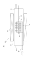
- FIG. FIG. 4 is a diagram for explaining a schematic configuration of an apparatus used for carrying out a verification example
- a CNT aggregate can be efficiently produced.
- Operations or components are described as being “upstream” operations or components, and further operations or components are described as being “downstream” operations or components.
- the method for producing a CNT aggregate of the present invention is a production method for growing a carbon nanotube aggregate on a substrate having a catalyst on its surface, wherein the environment surrounding the catalyst is a reducing gas environment, and A formation step of heating at least one of them, and a growing step of growing the aggregate of carbon nanotubes by heating at least one of the catalyst and the source gas while making the ambient environment of the catalyst a source gas environment.
- the blade members are regularly rotated forward and reverse when the substrate is conveyed along the conveying direction from the upstream side to the downstream side by the swirling motion of the blade members.
- the blade member is configured to convey the base material in the conveying direction when it rotates forward, and to move the base material in the direction opposite to the conveying direction when it rotates in the reverse direction. Further, the total number of forward rotations in one cycle of the turning motion of the blade member is more than the total number of reverse rotations.
- the method for producing a CNT aggregate of the present invention may further include a cooling step, a separation/recovery step, and/or a recycling step as steps performed after the growth step. Details of these steps will be described later.
- the substrate that constitutes the substrate having a catalyst on its surface which is used in the production method of the present invention, can be formed by supporting a catalyst on the substrate.
- the substrate is a member capable of supporting a catalyst for synthesizing CNTs on its surface, and is not particularly limited, and members made of any material can be used. Among them, it is preferable that the substrate is made of a ceramic material containing at least one element selected from Al, Si, and Zr. Furthermore, the substrate is preferably made of a metal oxide containing at least one of Al, Si, and Zr, and more preferably zirconium dioxide (ZrO 2 ). The shape of the substrate is preferably particulate with an aspect ratio of less than 5.
- the "aspect ratio" of the substrate particles can be obtained by calculating the values of (major axis/width perpendicular to the major axis) for a plurality of arbitrarily selected particles on a microscope image and obtaining the average value.
- the substrate particles preferably have an apparent density of 2.0 g/cm 3 or more, preferably 3.8 g/cm 3 or more, more preferably 5.8 g/cm 3 or more. 0 g/cm 3 or less is preferable. If the apparent density of the particulate base material is equal to or higher than the above lower limit, the resulting CNT aggregate can be elongated.
- the base material particles are excellent in handleability, and the production efficiency of the CNT aggregate can be further increased.
- the particle diameter of the substrate particles is preferably 0.05 mm or more, more preferably 0.3 mm or more, preferably 10 mm or less, more preferably 2 mm or less, and even more preferably 1 mm or less. If the particle size of the substrate particles is at least the above lower limit, the obtained CNT aggregate can be elongated. Moreover, if the particle size of the substrate particles is equal to or less than the above upper limit, the production efficiency of the CNT aggregate can be further enhanced.
- the "particle size" of the substrate particles means the volume average particle size D50.
- the volume average particle diameter D50 represents the particle diameter at which the cumulative volume calculated from the smaller diameter side is 50% in the particle size distribution (volume basis) measured by the laser diffraction method for the base particles.
- the catalyst supported on the substrate is not particularly limited, and includes catalyst components such as nickel (Ni), iron (Fe), cobalt (Co), and molybdenum (Mo).
- the catalyst component preferably contains at least one metal of nickel (Ni), iron (Fe), cobalt (Co), and molybdenum (Mo) from the viewpoint of further increasing the production efficiency of the CNT aggregate.
- an underlayer formed of a material such as aluminum oxide, titanium oxide, titanium nitride, or silicon oxide can be provided as an underlayer for supporting the catalyst on the substrate.
- the method of supporting the catalyst (or catalyst layer) on the substrate surface is not particularly limited, and any existing method can be adopted.
- a rotating drum type coating apparatus equipped with a substantially cylindrical rotating drum.
- the base material is placed in a substantially cylindrical rotating drum, and the rotating drum is rotated about an inclined axis or a horizontal axis, thereby stirring the base material particles while containing the above-described catalyst component.
- a solution containing components capable of constituting the underlayer and base particles are used prior to spraying and drying the catalyst solution.
- substrate particles having a base layer on the surface can be obtained.
- base particles having the base layer and the catalyst supported in this order on the surface can be obtained.
- base particles as the base material, as a method for preparing a base material having a catalyst on its surface, in addition to the above, for example, the base particles are caused to undergo centrifugal swirl flow and vertical floating flow, and the catalyst Methods include the step of spraying the solution.
- the reducing gas is a gas that has at least one effect of reducing the catalyst, promoting the atomization of the catalyst, and improving the activity of the catalyst.
- the reducing gas for example, hydrogen gas, ammonia, water vapor, and mixed gas thereof can be applied.
- a mixed gas in which hydrogen gas is mixed with an inert gas such as helium gas, argon gas, or nitrogen gas can also be used as the reducing gas.
- a reducing gas is generally used in the formation process, but may be used in the growth process as appropriate.
- Raw material gases used for the synthesis of CNT aggregates include, for example, hydrocarbons such as methane, ethane, ethylene, propane, butane, pentane, hexane, heptane propylene, and acetylene; lower alcohols such as methanol and ethanol; Mention may be made of low carbon number oxygenates such as carbon. Moreover, these can also be used in mixture of multiple types. Furthermore, this raw material gas may be diluted with an inert gas as described above.
- the source gas preferably contains ethylene.
- ethylene By heating ethylene in a predetermined temperature range (700° C. or higher and 900° C. or lower), the decomposition reaction of ethylene is promoted, and when the decomposition gas comes into contact with the catalyst, CNTs can grow at high speed.
- the thermal decomposition time is too long, the decomposition reaction of ethylene proceeds too much, causing deactivation of the catalyst and adhesion of carbon impurities to the CNT aggregates.
- the thermal decomposition time is preferably in the range of 0.5 seconds to 10 seconds with respect to the ethylene concentration in the range of 0.1 volume % to 40 volume %.
- the heated channel volume is the volume of the channel heated to a predetermined temperature T° C. through which the raw material gas passes before coming into contact with the catalyst, and the raw material gas flow rate is the flow rate at 0° C. and 1 atm.
- a catalyst activation material may be added in the CNT growth process. Addition of the catalyst activation material can further improve the production efficiency and quality of the CNT aggregate.
- the catalyst activating substance used here is generally a substance containing oxygen, and any substance that does not significantly damage the CNTs at the growth temperature may be used. low carbon oxygenates such as nitrogen, carbon monoxide and carbon dioxide; alcohols such as ethanol and methanol; ethers such as tetrahydrofuran; ketones such as acetone; aldehydes; A mixture of Among these, water, oxygen, carbon dioxide, carbon monoxide, or tetrahydrofuran is preferred, and carbon dioxide is more preferred.
- the CNTs In the growth step, by growing the CNTs in a high-carbon environment containing a catalyst-activating substance, the CNTs can be grown while maintaining catalytic activity for a long period of time.
- the production efficiency of CNT aggregates can be further improved.
- the source gas contains ethylene
- the presence of carbon dioxide as a catalyst activator can further improve the quality of the obtained CNT aggregates and the production efficiency of the CNT aggregates. The reason is presumed to be as follows. First, in the CNT synthesis reaction, it has been found that ethylene as a carbon source and carbon dioxide as a catalyst activator have relatively low activity, respectively.
- the amount of the catalyst activation material added in the growth step may be, for example, carbon dioxide, 0.5% by volume or more, preferably 4% by volume or more, and 5% by volume or more of the atmosphere in the growth step. is more preferable, and is usually 40% by volume or less.
- a high carbon concentration environment means an atmosphere in which 0.1% by volume or more of the atmosphere in the growth process (hereinafter also referred to as “source gas environment”) is source gas.
- the ratio of the raw material gas in the high carbon concentration environment can be, for example, 40% by volume or less.
- the ratio of the source gas in the high carbon concentration environment is preferably 4% by volume or more, more preferably 5% by volume or more, even more preferably 10% by volume or more, and preferably 30% by volume or less.
- the catalytic activity is significantly improved, so even in a high carbon concentration environment, the catalyst does not lose its activity and the CNT aggregate can be grown for a long time. In addition, the growth rate can be remarkably improved.
- the reaction temperature for growing the CNT aggregate is not particularly limited, and can be, for example, 400° C. or higher and 1100° C. or lower. Furthermore, when the source gas contains ethylene, the temperature is preferably 700°C or higher and 900°C or lower.
- the formation step is a step of making the environment around the catalyst supported on the base material a reducing gas environment and heating at least one of the catalyst and the reducing gas.
- a formation process is performed before the growth process mentioned later.
- reducing gas supply step As a result, the substrate having the catalyst on the surface and the reducing gas can be brought into contact with each other efficiently, and the catalyst supported on the surface of the substrate can be sufficiently activated in the formation process, thereby assembling CNTs. Body production efficiency and carbon conversion efficiency can be further increased.
- the base material may form a "base material layer" by stacking the base material on the lower part of the formation furnace by gravity or the like.
- the base material in the formation furnace is mechanically stirred and further conveyed by the blade members in the conveying direction from the upstream side to the downstream side (hereinafter also referred to as the “stirring and conveying step”. ) can be done.
- the supply of the reducing gas and the stirring and conveying of the base material can be performed at the same time or at a timing such that at least a part of them overlap.
- the reducing gas supplying process and the stirring and conveying process may all overlap. may be done.
- the blade member used in the agitating and conveying process may be a screw, paddle, or ribbon, or a combination thereof. At least one effect of reduction of the catalyst, promotion of fine particle formation in a state suitable for the growth of CNTs in the catalyst, and improvement in activity of the catalyst appears due to the agitating and conveying step by means of the blade member.
- the reducing gas may be supplied in any way in the furnace space of the formation furnace. It is preferable from the viewpoint of improving the contact efficiency between the reducing gas and the substrate that the reducing gas is supplied to the substrate layer from a plurality of gas injection ports arranged in the lower part of the furnace. At this time, it is preferable that the base material layer is mechanically stirred and/or conveyed in order to further improve the contact efficiency between the reducing gas and the base material. As a result, a reduction in the amount of reducing gas used and a shortening of the formation process can be expected, and the quality of the obtained CNT aggregates and the production efficiency of the CNT aggregates can be further improved.
- the reducing gas is continuously supplied so that the base material and the reducing gas come into contact with each other in the co-current and counter-current states in the furnace space of the formation furnace. .
- the substrate and the reducing gas conveyed by the blade members are brought into contact with each other in the states of co-current and counter-current, so that the substrate is reduced during the period in which the substrate is conveyed in the formation furnace. can efficiently secure the contact time between the and the reducing gas.
- the contact efficiency between the two can be improved by realizing both of the parallel flow and the counter flow instead of selecting either one of the parallel flow and the counter flow as the direction of contact between the two.
- by properly arranging the introduction position and the exhaust position of the reducing gas it is possible to optimize the retention time of the reducing gas in the manufacturing apparatus. This also makes it possible to further improve the quality of the obtained CNT aggregate and the production efficiency of the CNT aggregate.
- the temperature of the catalyst carrier or reducing gas atmosphere in the formation step is preferably 400°C or higher and 1100°C or lower.
- the execution time of the formation process may be 3 minutes or more and 120 minutes or less.
- the growth step is to use the surrounding environment of the catalyst, which has been brought into a state suitable for the production of CNT aggregates by the formation step described above, as the source gas environment, and to heat at least one of the catalyst and the source gas to form CNT aggregates. It is the process of growing the body.
- the base material is preferably supplied with a raw material gas from the lower side of the growth furnace in the growth furnace for performing the growth step (hereinafter also referred to as "raw material gas supply step"). .
- raw material gas supply step a raw material gas supply step
- the base material may form a "base material layer" by stacking the base material on the lower part of the furnace by gravity or the like in the growth furnace, as in the formation step.
- the substrate in the growth furnace is mechanically stirred using a blade member, and further, a stirring and conveying step can be performed in which the substrate is conveyed in the conveying direction from the upstream side to the downstream side. can. It is preferable that the raw material gas supplying step and the stirring and conveying step are performed at least partially overlapping each other.
- the source gas supplying step and the agitating and conveying step may all be performed in an overlapping manner.
- the uniformity of the gas to be supplied it is preferable that at least the raw material gas supply process overlaps with the stirring and conveying process, and it is more preferable that both the raw material gas supplying process and the stirring and conveying process overlap.
- the vane members used in the agitating and conveying process can be screws, paddles, or ribbons, or a combination of a plurality of them, as in the formation process.
- the raw material gas is injected into a plurality of gas injection ports arranged in the lower part of the growth furnace. is preferably supplied to the substrate layer from By supplying the raw material gas in this way, the raw material gas is supplied from the lower part of the base material layer, and the contact efficiency between the raw material gas and the base material can be improved. Furthermore, since the substrate layer can be mechanically stirred and/or transported, this also can further improve the contact efficiency between the source gas and the substrate.
- the supply amount of the raw material gas is such that the reciprocal of the average time for the gas to pass through the substrate layer formed in the lower part of the growth furnace is approximately equal to or greater than the CNT synthesis reaction rate coefficient per volume of the substrate layer. It is preferable to set By doing so, the CNT synthesis process becomes reaction rate-determining, so that it is possible to make the optimal growth time substantially the same when the reactor vessel is scaled up.
- the base material and the raw material gas conveyed by the blade members are brought into contact with each other in the state of co-current and counter-current in the furnace space of the growth furnace.
- the raw material gas is preferably supplied continuously.
- the quality of the obtained CNT aggregate and the production efficiency of the CNT aggregate can be further improved.
- by appropriately arranging the introduction position and the exhaust position of the raw material gas it is possible to optimize the residence time of the raw material gas in the manufacturing apparatus. This also makes it possible to further improve the quality of the obtained CNT aggregate and the production efficiency of the CNT aggregate.
- the blade member is rotated periodically to convey the base material along the conveying direction from the upstream side to the downstream side by the swirling motion of the blade member.
- the operation is repeated over a plurality of cycles, with the positive rotation and reverse rotation being one cycle of operation.
- the blade member is configured to convey the base material in the conveying direction when it rotates forward, and to move the base material in the direction opposite to the conveying direction when it rotates in the reverse direction.
- the base material is not simply conveyed unilaterally along the conveying direction, but is sometimes caused to flow backward.
- the production efficiency of the CNT aggregate can be enhanced, and the carbon conversion efficiency can be enhanced in the growth process.
- the total number of forward rotations in one cycle is greater than the total number of reverse rotations.
- the number of forward rotations in one cycle is greater than the number of reverse rotations by 0.5 rotations (that is, half a rotation) or more. Moreover, the difference between the total number of forward rotations and the total number of reverse rotations in one cycle is preferably 5 rotations or less.
- the rotational speed of the blade member is preferably 1 rpm or more, more preferably 2 rpm or more.
- the upper limit of the rotation speed is not particularly limited, but may be 10 rpm or less.
- a cooling step can be performed after the growing step.
- the CNT aggregate, catalyst, and substrate obtained in the growth step are cooled in an inert gas environment. Since the CNT aggregate, catalyst, and substrate after the growth process are in a high-temperature state, they tend to be easily oxidized when placed in an oxygen-existing environment. Therefore, it is preferable to cool the oriented aggregate of CNTs, the catalyst, and the substrate to 400° C. or less, more preferably 200° C. or less, in an inert gas environment.
- the separating and collecting step the aggregate of carbon nanotubes is separated from the substrate, and the aggregate of carbon nanotubes and the substrate are recovered separately.
- the recovery method is not particularly limited, and any known method can be adopted. Among them, a separation and recovery method using an external force and a fluid flow as a drag force of the external force (e.g., an air vortex formed by a centrifugal force and an air flow as a drag force of the centrifugal force) (e.g., International Publication No. 2019/ 188979) is preferably employed.
- the carbon on the recovered substrate is removed by oxidation to make the substrate reusable.
- the oxidation removal method is not particularly limited, and includes, for example, a method of heating the substrate while circulating air.
- the specific surface area of the CNT aggregate obtained by the production method of the present invention is determined by measuring the adsorption/desorption isotherm of liquid nitrogen at 77 K for CNTs that have not been subjected to an opening treatment, and using this adsorption/desorption isotherm, Brunauer, Emmett, Teller It is a value measured from the method of
- the specific surface area of a CNT aggregate can be measured using a BET specific surface area measuring device conforming to JIS Z8830.
- the specific surface area of the CNT obtained by the present invention is not particularly limited, but for example, it is preferably 600 m 2 /g or more, preferably 800 m 2 /g or more, and preferably 2600 m 2 /g or less. , 1400 m 2 /g or less. Furthermore, it is preferable that the specific surface area of the CNT aggregate subjected to the opening treatment is 1300 m 2 /g or more.
- the carbon nanotube aggregate production apparatus of the present invention is an apparatus for producing carbon nanotube aggregates by growing CNT aggregates on a base material having a catalyst on its surface.
- the apparatus for producing a carbon nanotube aggregate of the present invention includes a formation furnace that realizes a formation process of heating at least one of the catalyst and the reducing gas while making the environment around the catalyst a reducing gas environment, and an environment around the catalyst.
- a growth furnace that provides a source gas environment and heats at least one of the catalyst and the source gas to realize a growth step of growing the aggregate of carbon nanotubes.
- At least one of the formation furnace and the growth furnace is provided with a stirring and conveying unit that stirs and conveys the base material layer stacked thereunder in the conveying direction by means of the swirling motion of the blade members.
- the blade member is configured to convey the base material layer in the conveying direction when it rotates forward, and to move the base material layer in the direction opposite to the conveying direction when it rotates in the reverse direction.
- the blade member can be set such that regular forward and reverse rotation is defined as one cycle, and this cycle is repeated for a plurality of cycles, and the total number of forward rotations in one cycle is greater than the total number of reverse rotations.
- the settable rotational speed of the blade member is preferably 1 rpm or more, more preferably 2 rpm or more.
- the rotational speed of the blade member can be set to the lower limit value or higher, the production efficiency of the CNT aggregate and the carbon conversion efficiency can be further enhanced.
- the upper limit of the rotational speed that can be set for the blade member is not particularly limited, it can be 10 rpm or less.
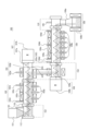
- FIG. 1 is a diagram for explaining a schematic configuration of a CNT aggregate manufacturing apparatus according to one example of the present invention.
- the CNT aggregate manufacturing apparatus 100 has a formation furnace 102, a growth furnace 104, and a base layer formed by depositing a base material in each furnace from the formation furnace 102 to the growth furnace 104 by rotating motion.
- Blade members 107a and 108a are provided for stirring and conveying in the conveying direction from the upstream side to the downstream side.
- the CNT aggregate manufacturing apparatus 100 prevents mutual mixing of gases between the connection portion 154 that spatially connects the formation furnace 102 and the growth furnace 104 and the formation furnace 102 and the growth furnace 104. and a gas anti-admixture device 103 to prevent. Furthermore, the CNT aggregate manufacturing apparatus 100 includes an inlet purge device 101 arranged before the formation furnace 102, an outlet purge device 105 arranged after the growth furnace 104, and further arranged after the outlet purge device 105. A component such as the cooling unit 106 may be provided.
- the blade members 107a and 108a are configured to convey the base material layer in the conveying direction when rotating in the forward direction, and to move the base material layer in the direction opposite to the conveying direction when rotating in the reverse direction.
- at least one of the blade member 107a included in the formation furnace 102 and the blade member 108a included in the growth furnace 104 periodically rotates in the forward and reverse directions as one cycle, and this cycle is repeated multiple times. Further, the total number of forward rotations in one cycle can be set to be greater than the total number of reverse rotations.
- the main components that the CNT aggregate manufacturing apparatus 100 may have are listed below from the upstream side to the downstream side: - Hopper 151; - Antechamber 152 (with inlet purge device 101); - First agitating and conveying unit (for formation process) 107 (provided with first blade member 107a and first driving device 107b) - connection part 153; Formation furnace 102 (including formation furnace body 102a, reducing gas injection port 102b, heating device 102c, and exhaust device 102d); - Gas mixture prevention device 103 (provided with purge gas injection port 103a and exhaust port 103b); - connection part 154; - Second agitating and conveying unit (for growing process) 108 (equipped with second blade member 108a and second driving device 108b); - A growth furnace 104 (including a growth furnace body 104a, a source gas injection port 104b, a heating device 104c, and an exhaust device 104d); - connection 110 (with outlet purge device 105); and
- the inlet purge device 101 consists of a set of devices for preventing outside air from entering the device furnace from the substrate inlet. It has a function of replacing the surrounding environment of the substrate transported into the CNT aggregate manufacturing apparatus 100 with a purge gas. Examples include a furnace or chamber for holding the purge gas, injection ports for injecting the purge gas, and the like.
- the purge gas is preferably an inert gas, and particularly preferably nitrogen from the viewpoints of safety, cost, purging properties, and the like. A small amount of hydrogen may be included for the purpose of improving catalytic activity.
- the purge gas injection port is connected to an air supply device configured to be able to inject purge gas in a shower form from above and below to exhibit a gas curtain function, thereby facilitating the CNT aggregate manufacturing apparatus. It is preferable to be configured so as to be able to prevent external air from entering from the 100 inlet.
- the inlet purge device 101 is attached to a connecting portion 153 that connects an antechamber 152, which is a component for introducing the base material into the system via a hopper 151, and the formation furnace main body 102a. ing.
- the formation furnace 102 consists of a set of devices for realizing the formation process.
- the formation furnace 102 has the function of making the environment surrounding the catalyst formed on the surface of the base material a reducing gas environment and heating at least one of the catalyst and the reducing gas.
- the formation furnace 102 includes, for example, a formation furnace body 102a for holding reducing gas, a reducing gas injection port 102b for injecting the reducing gas, a heating device 102c for heating at least one of the catalyst and the reducing gas, and a furnace interior.
- the heating device 102c is not particularly limited, and can be implemented by, for example, a resistance heater, an infrared heater, an electromagnetic induction heater, or the like. Moreover, the heating device 102c can heat the inside of the system so that the temperature in the formation furnace is 400° C. or higher and 1100° C. or lower. Furthermore, the exhaust device 102d is a component for exhausting reducing gas in the furnace, including a reducing gas exhaust port arranged on the side surface of the furnace body of the formation furnace main body 102a.
- the formation furnace 102 preferably has at least one reducing gas exhaust port, and may have more than one.
- the growth furnace 104 consists of a set of devices for realizing the growth process.
- the growth furnace 104 uses the surrounding environment of the catalyst, which has been brought into a state suitable for the production of CNT aggregates by the formation process in the formation furnace 102, as a source gas environment, and heats at least one of the catalyst and the source gas to produce CNTs. It has the function of growing aggregates.
- the growth furnace 104 includes a growth furnace main body 104a for maintaining the source gas environment, a source gas injection port 104b for injecting the source gas, and a heater for heating at least one of the catalyst and the source gas.
- the heating device 104c is not particularly limited, and can be implemented by, for example, a resistance heater, an infrared heater, an electromagnetic induction heater, or the like.
- the growth furnace 104 preferably has a catalyst activation material addition device.
- the exhaust device 104d is a component for exhausting the raw material gas in the furnace to the outside of the system, including the raw material gas exhaust port arranged on the side surface of the furnace body of the growth furnace main body 104a.
- the growth furnace 104 preferably has at least one source gas exhaust port, and may have more than one.
- the catalyst activator adding device comprises a set of devices for adding the catalyst activator to the raw material gas or directly adding the catalyst activator to the surrounding environment of the catalyst in the growth furnace space. Illustration of the catalyst activation material addition device is omitted in FIG.
- the catalyst activation material addition device is not particularly limited for supplying the catalyst activation material, but for example, supply by bubbler, supply by evaporating the solution containing the catalyst activation agent, supply as gas , and a supply system capable of supplying the solid catalyst activator after liquefying or vaporizing it.
- Such delivery systems may include, for example, vaporizers, mixers, agitators, diluters, atomizers, pumps, compressors, and the like.
- a catalyst activator concentration measuring device may be provided in a catalyst activator supply pipe or the like. By performing feedback control using this output value, it is possible to stably supply the catalyst activation material with little change over time.
- the agitating and conveying units (first and second) 107 and 108 are units for agitating and/or conveying the base material layer formed by depositing the base material 112 .
- the vane members 107a and 108a that constitute the agitating and conveying unit may be screws, paddles, ribbons, or a combination thereof.
- vane members 107a and 108a may be implemented as screw vanes.
- the blade members 107a and 108a implemented as screw blades and the driving devices 107b and 108b corresponding thereto can be combined to function as a screw conveyor.
- Drives 107b and 108b may each be a motor.
- the substrate 112 can be introduced into the apparatus from outside the system via a hopper 151, for example. Further, the vicinity of the driving devices 107b and 108b may be heated by a heating device (not shown) configured to heat the inside of the system at a temperature lower than the heating temperature in the formation furnace 102.
- the diameter and winding pitch of the blade members 107a and 108a can be arbitrarily adjusted according to the size of the substrate 112 to be used.
- first stirring-conveying unit 107 and the second stirring-conveying unit 108 may be arranged at an angle rather than parallel to each other. Such an angle can be, for example, 10° or less.
- the first driving device 107b is arranged on the downstream side of the formation furnace 102, and the second driving device 108b is arranged on the upstream side of the growth furnace 104.
- the formation furnace 102 and the growth furnace 104 so that their ends on the side where the driving devices 107b and 108b are not installed are movably held while the connecting portion between the formation furnace 102 and the growth furnace 104 is fixed. be possible.
- the components to be heated such as the formation furnace main body 102a and the growth furnace main body 104a thermally expand and change in size, the ends of these components are movably held. , the device load caused by heat can be suppressed.
- the gas contamination prevention device 103 is installed at a connecting portion 154 that spatially connects the formation furnace 102 and the growth furnace 104 to each other, and prevents gases from mutually mixing into the furnace spaces of the formation furnace 102 and the growth furnace 104. It consists of a set of devices for realizing the function of preventing
- the gas contamination prevention device 103 is not particularly limited, and can be a gate valve device or a rotary device that can mechanically cut off the spatial connection between the formation furnace 102 and the growth furnace 104 at times other than when the substrate is moving.
- the gas mixture prevention device 103 also has a purge gas injection port 103a that injects a purge gas (seal gas) along the opening surface of the connecting portion 154, and the exhaust port 103b sucks the purge gas. It is preferable that the gas is exhausted to the outside of the manufacturing apparatus.
- the CNT aggregate manufacturing apparatus 100 having such a configuration, the reduction of the catalyst in the formation process is less likely to be inhibited, and the quality of the obtained CNT aggregates and the production efficiency of the CNT aggregates can be further improved.
- these can also be used together with a gate valve device and/or a rotary valve device.
- the cooling unit 106 consists of a set of devices necessary for cooling the substrate on which the CNT aggregates are grown.
- the cooling unit 106 has a function of preventing oxidation and cooling of the CNT aggregate, catalyst, and substrate after the growth process in the growth furnace 104 .
- the cooling unit 106 shown in FIG. 1 includes a cooling container 106a for holding inert gas and a water-cooling cooling device 106b arranged so as to surround the space inside the cooling container 106a. It should be noted that regardless of the illustrated embodiment, if the cooling unit is an air-cooled type, the cooling unit may be provided with an injection section or the like for injecting an inert gas into the cooling container inner space.
- the cooling vessel 106a is connected to the growth reactor main body 104a via a connecting portion 110. As shown in FIG.
- connections 153 , 154 , 110 include, for example, furnaces or chambers that are insulated from the environment surrounding the substrates and outside air and that allow substrates 112 to be moved between objects to be connected.
- the outlet purge device 105 consists of a set of devices for preventing outside air from entering the device furnace from the substrate outlet.
- the outlet purge device 105 has the function of turning the ambient environment of the substrate 112 into a purge gas environment.
- the outlet purge device 105 may be implemented by a furnace or chamber for maintaining the purge gas environment, an injector for injecting the purge gas, or the like.
- the purge gas is preferably an inert gas, and particularly preferably nitrogen from the viewpoints of safety, cost, purging properties, and the like.
- a gas curtain device for spraying the purge gas from above and below in the form of a shower as a purge gas spraying part to prevent external air from entering from the device outlet.
- the CNT assembly manufacturing apparatus 100 may include a reducing gas injection port 102b, a raw material gas injection port 104b, a catalyst activation material injection port (not shown), and an injection mechanism such as a pump connected to these.
- the formation furnace 102 may include a reducing gas injection device including a plurality of reducing gas injection ports 102b arranged at the bottom and an injection mechanism connected thereto.
- the growth furnace 104 may include a raw material gas injection device configured by a plurality of raw material gas injection ports 104b arranged in the lower portion and an injection mechanism connected thereto.
- the raw material gas injection port 104b and the reducing gas injection port 102b may have various shapes such as circular, oval, rectangular, and slit shapes. When base particles are used, a slit shape is preferred.
- equipment parts exposed to reducing gas or raw material gas such as formation furnace 102, growth furnace 104, transfer units 107 to 108, gas contamination prevention device 103, connection parts 153, 154, 110
- Materials that can withstand high temperatures include, for example, quartz, heat-resistant ceramics, and heat-resistant alloys. Heat-resistant alloys are preferred from the viewpoints of precision and flexibility in processing and cost. Heat-resistant alloys include heat-resistant steel, stainless steel, nickel-based alloys, and the like. A steel containing Fe as a main component and containing other alloys in an amount of 50% or less is generally called a heat-resistant steel.
- Nickel-based alloys include alloys obtained by adding Mo, Cr, Fe, and the like to Ni. Specifically, SUS310, Inconel 600, Inconel 601, Inconel 625, Incoloy 800, MC alloy, Haynes 230 alloy and the like are preferable from the viewpoints of heat resistance, mechanical strength, chemical stability and low cost.
- FIG. 1 exemplifies a configuration in which the formation furnace 102 and the growth furnace 104 are provided as separate vertically spaced components, and are connected in series by the connecting portion 154 .
- the substrates are transported by two separate transport units.
- the device configuration of the CNT aggregate manufacturing device is not limited to such a configuration.
- CNT carbon nanotube
- Example 1 In manufacturing the CNT aggregates, a CNT aggregate manufacturing apparatus having the schematic configuration shown in FIG. 1 was used.
- the formation furnace, the growth furnace, the reducing gas injection port, the raw material gas injection port, the exhaust device of the gas mixture prevention device, the screw blades, the purge sections, and the connection section were each formed of Inconel 601 .
- Zirconia (zirconium dioxide) beads (ZrO 2 , volume average particle diameter D50: 650 ⁇ m; apparent density: 6.0 g/cm 3 ) as a base material are put into a rotating drum coating device, and the zirconia beads are stirred (20 rpm).
- the aluminum-containing solution is sprayed with a spray gun (spray amount 3 g / min, spray time 940 seconds, spray air pressure 10 MPa), and dried while supplying compressed air (300 L / min) into the rotating drum, An aluminum-containing coating was formed on the zirconia beads.
- a calcination treatment was performed at 480° C.
- primary catalyst particles having an aluminum oxide layer formed thereon.
- the primary catalyst particles were put into another rotary drum type coating device and stirred (20 rpm) while the iron catalyst solution was sprayed with a spray gun (spray amount: 2 g/min, spray time: 480 seconds, spray air pressure: 5 MPa). ) and dried while supplying compressed air (300 L/min) into the rotating drum to form an iron-containing coating film on the primary catalyst particles.
- a sintering treatment was performed at 220° C. for 20 minutes to produce a substrate on which an iron oxide layer was further formed.
- the base material having a catalyst on its surface prepared in this way was put into the feeder hopper of the manufacturing apparatus, and while being conveyed by the screw conveyor, the formation process, the growth process, and the cooling process were performed in order to manufacture a CNT aggregate. .
- the conditions for the hopper, inlet purge device, formation furnace, gas contamination prevention device, growth furnace, outlet purge device, and cooling unit of the CNT aggregate manufacturing equipment were set as follows.
- the CNT aggregates synthesized on the substrate were separated and collected using a forced vortex classifier (rotational speed: 1600 rpm, air volume: 2.5 Nm 3 /min). The average recovery of CNT aggregates was about 98%.
- the characteristics of the CNT aggregate produced by this example are, as typical values, tap bulk density: 0.006 g/cm 3 , average CNT length: 280 ⁇ m, BET specific surface area: 800 m 2 /g, average outer diameter: 4.0 nm, carbon purity: 99%, CNT yield: 8.4 mg/g-beads, carbon conversion efficiency: 21%.
- Table 1 shows the results of the continuous production.
- the average length of the CNT aggregates can be obtained by measuring the length by microscopically observing zirconia beads synthesized with 100 CNT aggregates and calculating the arithmetic mean value.
- Example 2 3 kg of the used base material used for the production of the CNT aggregate in Example 1 was collected, and subjected to oxidation treatment (atmosphere: air, temperature 800°C, treatment time 30 minutes) in a rotary kiln furnace, and adhered to the base material surface. A recycling step was performed to remove the carbon. Using the substrate after the recycling process, each process treatment was performed in the same manner as in Example 1 to produce a CNT aggregate.
- oxidation treatment atmosphere: air, temperature 800°C, treatment time 30 minutes
- the properties of the CNT aggregates produced in this example are almost the same as those in Example 1, except that the yield is 6.7 mg/g-beads, which is about 80% lower. there were.
- a CNT aggregate manufacturing apparatus (for verification) 200 includes a heating device 201, a formation and growth furnace 202, a gas injection port 203, a reducing gas/growth gas introduction port 204, an exhaust port 205, a paddle mixer 206, a substrate 207, a substrate It consists of a formation/growth unit 200 a with a holder 208 .
- the formation and growth furnace 202 are made of quartz and the paddle mixer and substrate holder are made of Inconel 601.
- a substrate having a catalyst on its surface which was produced in the same manner as in Example 1, is stacked from the furnace side port 209 into the substrate holder 208 of the CNT assembly manufacturing apparatus 200, and a plurality of gas are arranged on the bottom surface of the substrate holder 208.
- a formation process, a growth process, and a cooling process were performed in order while injecting various gases from the injection port 203 to manufacture a CNT aggregate.
- CNT assembly manufacturing apparatus 101 inlet purge device 102: formation furnace 102a: formation furnace main body 102b: reducing gas injection port 102c: heating device 102d: exhaust device 103: gas mixture prevention device 103a: purge gas injection port 103b: exhaust port 104: growth furnace 104a: growth furnace main body 104b: raw material gas injection port 104c: heating device 104d: exhaust device 105: outlet purge device 106: cooling unit 106a: cooling container 106b: water-cooled cooling device 107: first stirring and conveying unit (formation process) 107a: First blade member 107b: First driving device 108: Second stirring and conveying unit (for growth process) 108a: Second blade member 108b: Second driving device 110, 153, 154: Connection part 112: Base material 151: Hopper 152: Front chamber 200: CNT aggregate manufacturing device (for verification) 200a: Formation/growth unit 201: Heating device 202: Formation and growth furnace 203: Gas injection port 204: Reduction gas/source
Abstract
In the present invention, a CNT aggregate is produced using a base material that has a catalyst on the surface thereof, wherein in a formation step and/or a growing step, when using a vane member to convey the base material, an operation is repeated for a plurality of cycles, where one cycle of operation is defined as periodically causing forward rotation and reverse rotation of the vane member.
Description
本発明は、カーボンナノチューブ集合体の製造方法及び製造装置に関するものである。
The present invention relates to a method and apparatus for manufacturing carbon nanotube aggregates.
近年、導電性、熱伝導性及び機械的特性に優れる材料として、カーボンナノチューブ(以下、「CNT」と称することがある。)等のナノ炭素材料が注目されている。ナノ炭素材料は、優れた特性を発揮し得ることが認識されながらも、概して、製造コストが高いため他の材料よりも高価であった。
In recent years, nanocarbon materials such as carbon nanotubes (hereinafter sometimes referred to as "CNT") have attracted attention as materials with excellent electrical conductivity, thermal conductivity and mechanical properties. While it has been recognized that nanocarbon materials can offer superior properties, they have generally been more expensive than other materials due to their high manufacturing costs.
そこで従来から、ナノ炭素材料の効率的な生産を目的として、種々の試みがなされてきた。例えば、特許文献1では、カーボンナノチューブ集合体の製造に際して、フォーメーション工程と成長工程とをこの順に別途に実施すると共に、これらの工程にて、表面に触媒を有する基材を、スクリュー回転によって搬送することで、高品質なCNT集合体を効率的に生産する製造方法などが提案されている。また、例えば特許文献2では、含炭化水素化合物を触媒反応により熱分解させて、水素とともに超微粉炭素を生成させる触媒反応装置であって、回転式の搬送撹拌手段を有する反応管を備える装置が開示されている。
Therefore, various attempts have been made for the purpose of efficient production of nanocarbon materials. For example, in Patent Document 1, when manufacturing carbon nanotube aggregates, a formation step and a growth step are separately performed in this order, and in these steps, a substrate having a catalyst on its surface is conveyed by screw rotation. Therefore, a manufacturing method for efficiently producing a high-quality CNT aggregate has been proposed. Further, for example, in Patent Document 2, a catalytic reaction device for thermally decomposing a hydrocarbon-containing compound by a catalytic reaction to generate ultrafine carbon together with hydrogen, which is equipped with a reaction tube having a rotary conveying and stirring means. disclosed.
ここで、上記従来技術に従うナノ炭素材料の製造方法には、カーボンナノチューブ集合体(以下、「CNT集合体」とも称することがある。)を製造する際の生産効率及び炭素変換効率を一層高めるという点で改善の余地があった。
Here, in the method for producing a nanocarbon material according to the conventional technology, it is said that the production efficiency and the carbon conversion efficiency in producing a carbon nanotube aggregate (hereinafter sometimes referred to as a "CNT aggregate") are further improved. There was room for improvement.
そこで、本発明は、カーボンナノチューブ集合体を製造する際の生産効率及び炭素変換効率を一層高めることができる、CNT集合体の製造方法及び製造装置を提供することを目的とする。
Therefore, an object of the present invention is to provide a method and apparatus for producing a CNT aggregate that can further improve the production efficiency and carbon conversion efficiency when producing a carbon nanotube aggregate.
本発明者らは、上記課題を解決することを目的として鋭意検討を行った。その結果、本発明者らは、表面に触媒を有する基材を用いてCNT集合体を製造するに際して、フォーメーション工程及び成長工程のうちの少なくとも一方において、羽根部材を用いて基材を搬送する際に、羽根部材を定期的に正回転及び逆回転させることを1サイクルの動作として、前記動作を複数サイクルにわたり繰り返すことにより、CNT集合体を製造する際の生産効率及び炭素変換効率を一層高めうることを新たに見出し、本願発明を完成させた。
The present inventors have conducted intensive studies with the aim of solving the above problems. As a result, the present inventors found that when producing a CNT aggregate using a substrate having a catalyst on its surface, in at least one of the formation process and the growth process, when the substrate is transported using a blade member, Furthermore, by repeating the above operation over a plurality of cycles, with regular forward and reverse rotation of the blade member as one cycle operation, the production efficiency and carbon conversion efficiency in manufacturing the CNT aggregate can be further increased. The present inventors have newly discovered that and completed the present invention.
即ち、この発明は、上記課題を有利に解決することを目的とするものであり、[1]本発明のCNT集合体製造方法は、表面に触媒を有する基材上にカーボンナノチューブ集合体を成長させる製造方法であって、前記触媒の周囲環境を還元ガス環境とすると共に前記触媒及び前記還元ガスのうち少なくとも一方を加熱するフォーメーション工程と、前記触媒の周囲環境を原料ガス環境とすると共に前記触媒及び前記原料ガスのうち少なくとも一方を加熱して前記カーボンナノチューブ集合体を成長させる成長工程と、をこの順で含み、さらに、前記フォーメーション工程及び成長工程のうちの少なくとも一方において、前記基材を羽根部材の旋回運動により、上流側から下流側に向かう搬送方向に沿い搬送するにあたり、前記羽根部材を定期的に正回転及び逆回転させることを1サイクルの動作として、前記動作を複数サイクルにわたり繰り返すことを含み、前記羽根部材は、正回転した際には前記基材を前記搬送方向に運搬し、逆回転した際には前記基材を前記搬送方向とは逆方向に移動させるように構成されており、前記1サイクルにおける前記正回転の総数が前記逆回転の総数よりも多いことを特徴とする。このような製造方法によれば、CNT集合体を製造する際の生産効率及び炭素変換効率を高めることができる。
That is, an object of the present invention is to advantageously solve the above problems. a formation step of heating at least one of the catalyst and the reducing gas while setting the surrounding environment of the catalyst to a reducing gas environment; and setting the surrounding environment of the catalyst to a source gas environment and the catalyst and a growth step of heating at least one of the raw material gases to grow the aggregate of carbon nanotubes, and further, in at least one of the formation step and the growth step, the substrate is covered with blades. When conveying along the conveying direction from the upstream side to the downstream side by the turning motion of the member, periodically rotating the blade member forward and backward is regarded as one cycle of operation, and the above operation is repeated over a plurality of cycles. wherein the blade member is configured to convey the base material in the conveying direction when rotated in the forward direction, and to move the base material in the direction opposite to the conveying direction when rotated in the reverse direction. and the total number of forward rotations in one cycle is greater than the total number of reverse rotations. According to such a manufacturing method, it is possible to increase the production efficiency and the carbon conversion efficiency when manufacturing the CNT aggregate.
[2]また、上記[1]のCNT集合体製造方法において、前記羽根部材の回転速度が1rpm以上であることが好ましい。このような製造方法によれば、CNT集合体を製造する際の生産効率及び炭素変換効率を一層高めることができる。
[2] In the CNT aggregate manufacturing method of [1] above, it is preferable that the rotational speed of the blade member is 1 rpm or more. According to such a production method, it is possible to further improve the production efficiency and carbon conversion efficiency when producing a CNT aggregate.
[3]また、上記[1]又は[2]のCNT集合体製造方法において、前記成長工程において、前記カーボンナノチューブ集合体の長さを180nm以上に成長させることが好ましい。このような製造方法によれば、高品質なCNT集合体を製造することができる。なお、CNT集合体の長さは、本明細書の実施例に記載した方法に従って測定することができる。
[3] In the method for producing a CNT aggregate according to [1] or [2] above, it is preferable to grow the carbon nanotube aggregate to a length of 180 nm or more in the growing step. According to such a production method, a high-quality CNT aggregate can be produced. In addition, the length of the CNT aggregate can be measured according to the method described in the examples of this specification.
[4]また、上記[1]~[3]の何れかのCNT集合体製造方法において、前記フォーメーション工程において前記基材と前記還元ガスとが、並流及び向流の状態で相互に接触するように、前記還元ガスが供給されること、及び、前記成長工程において、前記基材と前記原料ガスとが、並流及び向流の状態で相互に接触するように、前記原料ガスが供給されること、のうち少なくとも一方を実施することが好ましい。このような製造方法によれば、CNT集合体を製造する際の生産効率及び炭素変換効率を一層高めることができる。
[4] In the method for producing a CNT aggregate according to any one of [1] to [3] above, in the formation step, the base material and the reducing gas are brought into contact with each other in a state of cocurrent flow and countercurrent flow. and, in the growth step, the source gas is supplied such that the base material and the source gas are in contact with each other in cocurrent and countercurrent states. It is preferable to implement at least one of According to such a production method, it is possible to further improve the production efficiency and carbon conversion efficiency when producing a CNT aggregate.
[5]また、上記[1]~[4]の何れかのCNT集合体製造方法において、前記フォーメーション工程を実現するフォーメーション炉と、前記成長工程を実現する成長炉と、前記フォーメーション炉の炉内空間と前記成長炉の炉内空間とを空間的に接続する接続部と、前記フォーメーション炉の前記炉内空間と前記成長炉の前記炉内空間との間でガスが相互に混入することを防止するガス混入防止装置と、を有する製造装置を用い、前記羽根部材により前記基材を連続的に搬送しながら、前記各工程におけるガス環境が相互に混入することを防止しつつ、前記フォーメーション工程と前記成長工程とを実施することが好ましい。このような製造方法によれば、CNT集合体を製造する際の生産効率及び品質を一層高めることができる。
[5] In the method for producing a CNT aggregate according to any one of [1] to [4] above, a formation furnace for realizing the formation step, a growth furnace for realizing the growth step, and an interior of the formation furnace A connecting portion that spatially connects a space and an in-furnace space of the growth furnace, and preventing mutual mixing of gases between the in-furnace space of the formation furnace and the in-furnace space of the growth furnace. and a gas contamination prevention device that prevents the gas environment in each of the steps from being mixed with each other while continuously conveying the base material by the blade member, and the formation step and the It is preferable to perform the growth step. According to such a manufacturing method, it is possible to further improve the production efficiency and quality when manufacturing a CNT aggregate.
[6]また、上記[1]~[5]の何れかのCNT集合体製造方法において、前記フォーメーション工程において、フォーメーション炉の下部側から前記基材に対して前記還元ガスを供給すること、又は、前記成長工程において、前記成長炉の下部側から前記基材に対して前記原料ガスを供給すること、をさらに含むことが好ましい。このような製造方法によれば、CNT集合体を製造する際の生産効率及び炭素変換効率を一層高めることができる。
[6] Further, in the CNT aggregate manufacturing method according to any one of [1] to [5] above, in the formation step, the reducing gas is supplied from the lower side of the formation furnace to the base material, or and supplying the raw material gas to the base material from the lower side of the growth furnace in the growing step. According to such a production method, it is possible to further improve the production efficiency and carbon conversion efficiency when producing a CNT aggregate.
[7]また、上記[1]~[6]の何れかのCNT集合体製造方法において、前記成長工程における前記原料ガス環境が、高炭素濃度環境であり且つ触媒賦活物質を含むことが好ましい。このような製造方法によれば、CNT集合体を製造する際の生産効率及び炭素変換効率を一層高めることができる。
[7] In the method for producing a CNT aggregate according to any one of [1] to [6] above, it is preferable that the source gas environment in the growth step is a high carbon concentration environment and contains a catalyst activating substance. According to such a production method, it is possible to further improve the production efficiency and carbon conversion efficiency when producing a CNT aggregate.
[8]また、上記[1]~[7]の何れかのCNT集合体製造方法において、前記原料ガス環境が、エチレン、及び、触媒賦活物質としての二酸化炭素を含むことが好ましい。このような製造方法によれば、CNT集合体を製造する際の生産効率及び炭素変換効率を一層高めることができる。
[8] In the method for producing a CNT aggregate according to any one of [1] to [7] above, it is preferable that the source gas environment contains ethylene and carbon dioxide as a catalyst activation substance. According to such a production method, it is possible to further improve the production efficiency and carbon conversion efficiency when producing a CNT aggregate.
[9]また、上記[1]~[8]の何れかのCNT集合体製造方法において、前記基材が、見かけ密度2.0g/cm3以上の粒子であることが好ましい。このような製造方法によれば、CNT集合体を製造する際の生産効率及び炭素変換効率を一層高めることができる。なお、支持体の「見かけ密度」とは、支持体が内部に空隙(閉気孔)をもつ粒子である場合には、その空隙を含めた単位容積当たりの質量を意味する。「支持体の見かけ密度」は、ピクノメーター法に従って測定することができる。
[9] In the method for producing a CNT aggregate according to any one of [1] to [8] above, it is preferable that the base material is particles having an apparent density of 2.0 g/cm 3 or more. According to such a production method, it is possible to further improve the production efficiency and carbon conversion efficiency when producing a CNT aggregate. The "apparent density" of the support means the mass per unit volume including the voids when the support is particles having voids (closed pores) inside. The "apparent density of the support" can be measured according to the pycnometer method.
[10]また、上記[1]~[9]の何れかのCNT集合体製造方法において、前記基材が、Al、Si、及びZrのいずれか1つ以上の元素を含むこと好ましい。Al、Si、及びZrのうちの1つ以上の元素を含む基材を用いることで、CNT集合体の生産効率を一層向上させることができる。
[10] In addition, in the method for producing a CNT aggregate according to any one of [1] to [9] above, it is preferable that the substrate contains at least one element of Al, Si, and Zr. By using a substrate containing one or more elements of Al, Si, and Zr, the production efficiency of CNT aggregates can be further improved.
[11]また、上記[1]~[10]の何れかのCNT集合体製造方法において、前記基材上に触媒を担持させる触媒層形成工程と、前記カーボンナノチューブ集合体を前記基材から分離し、基材とカーボンナノチューブ集合体を別々に回収する分離回収工程と、回収された前記基材上の炭素を酸化除去することで前記基材を再利用可能にする再利用工程と、を含むことが好ましい。かかる分離回収工程及び再利用工程を実施することで、CNT集合体の生産効率を一層向上させることができる。
[11] Further, in the method for producing a CNT aggregate according to any one of [1] to [10] above, a catalyst layer forming step of supporting a catalyst on the base material, and separating the carbon nanotube aggregate from the base material and a separation and recovery step of separately recovering the substrate and the aggregate of carbon nanotubes, and a recycling step of making the substrate reusable by oxidizing and removing the carbon on the recovered substrate. is preferred. By carrying out such a separation/recovery process and a recycling process, the production efficiency of CNT aggregates can be further improved.
[12]本発明のカーボンナノチューブ集合体の製造装置は、表面に触媒を有する基材上にカーボンナノチューブ集合体を成長させる製造装置であって、前記触媒の周囲環境を還元ガス環境とすると共に前記触媒及び前記還元ガスのうち少なくとも一方を加熱するフォーメーション工程を実現するフォーメーション炉と、前記触媒の周囲環境を原料ガス環境とすると共に前記触媒及び前記原料ガスのうち少なくとも一方を加熱して前記カーボンナノチューブ集合体を成長させる成長工程を実現する成長炉と、前記フォーメーション炉から前記成長炉を通過するまでの間に、前記基材が堆積してなる基材層を旋回運動によって撹拌し、且つ、搬送方向に搬送する羽根部材を備える撹拌搬送ユニットと、を備え、さらに、前記羽根部材は、正回転した際には前記基材層を前記搬送方向に運搬し、逆回転した際には前記基材層を前記搬送方向とは逆方向に移動させるように構成されており、前記フォーメーション炉及び前記成長炉のうちの少なくとも一方に含まれる前記羽根部材が、定期的に正回転及び逆回転することを1サイクルとして、これを複数サイクル繰り返し、さらに前記1サイクルにおける前記正回転の総数が前記逆回転の総数よりも多くなるように設定可能である、ことを特徴とする。このような製造装置は、CNT集合体を製造する際の生産効率及び炭素変換効率に優れる。
[12] An apparatus for producing a carbon nanotube aggregate of the present invention is an apparatus for growing a carbon nanotube aggregate on a substrate having a catalyst on its surface, wherein the environment surrounding the catalyst is a reducing gas environment and the a formation furnace for realizing a formation step of heating at least one of the catalyst and the reducing gas; and an environment surrounding the catalyst is used as a source gas environment, and at least one of the catalyst and the source gas is heated to produce the carbon nanotubes. a growth furnace for realizing a growth process for growing aggregates, and a base material layer formed by depositing the base material being agitated by a revolving motion and transported between the formation furnace and the growth furnace. a stirring and conveying unit comprising a blade member for conveying in a direction, wherein the blade member conveys the base material layer in the conveying direction when rotating in the forward direction, and conveys the base material layer in the conveying direction when rotating in the reverse direction. It is configured to move the layer in a direction opposite to the transport direction, and the blade members included in at least one of the formation furnace and the growth furnace regularly rotate forward and backward. A plurality of cycles are repeated as one cycle, and the total number of forward rotations in one cycle can be set to be larger than the total number of reverse rotations. Such a production apparatus is excellent in production efficiency and carbon conversion efficiency when producing CNT aggregates.
[13]また、上記[12]のカーボンナノチューブ集合体の製造装置は、前記撹拌搬送ユニットの前記羽根部材が、回転速度1rpm以上に設定可能であることが好ましい。このような製造装置によれば、CNT集合体を製造する際の生産効率及び炭素変換効率を一層高めることができる。
[13] Further, in the carbon nanotube assembly manufacturing apparatus of [12] above, it is preferable that the blade member of the stirring and conveying unit can be set to a rotational speed of 1 rpm or more. According to such a manufacturing apparatus, it is possible to further improve the production efficiency and carbon conversion efficiency when manufacturing CNT aggregates.
[14]また、上記[12]又は[13]のカーボンナノチューブ集合体の製造装置は、前記フォーメーション炉の炉内空間と前記成長炉の炉内空間とを空間的に接続する接続部と、前記フォーメーション炉の前記炉内空間と、前記成長炉の前記炉内空間との間で、ガスが相互に混入することを防止するガス混入防止装置と、をさらに備えることが好ましい。このような製造装置によれば、CNT集合体を製造する際の生産効率及び品質を一層高めることができる。
[14] Further, the apparatus for producing a carbon nanotube aggregate according to [12] or [13] above includes a connecting portion that spatially connects the furnace space of the formation furnace and the furnace space of the growth furnace; It is preferable to further include a gas contamination prevention device for preventing mutual mixing of gas between the furnace space of the formation furnace and the furnace space of the growth furnace. According to such a manufacturing apparatus, it is possible to further improve production efficiency and quality when manufacturing CNT aggregates.
[15]また、上記[12]~[14]の何れかのカーボンナノチューブ集合体の製造装置は、前記フォーメーション炉が、下部に配列された複数個の還元ガス噴射口を有し、当該還元ガス噴射口から前記還元ガスを前記基材層に対して供給可能に構成された還元ガス噴射装置を備えるか、又は、
前記成長炉が、下部に配列された複数個の原料ガス噴射口を有し、当該原料ガス噴射口から前記原料ガスを前記基材層に対して供給可能に構成された原料ガス噴射装置を備えることが好ましい。このような製造装置によれば、CNT集合体を製造する際の生産効率及び炭素変換効率を一層高めることができる。 [15] Further, in the apparatus for producing a carbon nanotube aggregate according to any one of [12] to [14] above, the formation furnace has a plurality of reducing gas injection ports arranged in a lower portion, and the reducing gas a reducing gas injection device configured to be able to supply the reducing gas to the base material layer from an injection port, or
The growth furnace has a plurality of raw material gas injection ports arranged in a lower portion, and includes a raw material gas injection device configured to be able to supply the raw material gas from the raw material gas injection ports to the base material layer. is preferred. According to such a manufacturing apparatus, it is possible to further improve the production efficiency and carbon conversion efficiency when manufacturing CNT aggregates.
本発明によれば、カーボンナノチューブ集合体を製造する際の生産効率及び炭素変換効率を一層高めることができる、CNT集合体の製造方法及び製造装置を提供することができる。
According to the present invention, it is possible to provide a method and apparatus for producing a CNT aggregate that can further improve the production efficiency and carbon conversion efficiency when producing a carbon nanotube aggregate.
以下、本発明の実施形態について、図面を参照して詳細に説明する。本発明のカーボンナノチューブ集合体の製造方法及び製造装置によれば、CNT集合体を効率的に生産することができる。なお、以下の説明において、フォーメーション工程から成長工程、任意の冷却工程、分離工程へと処理が進行する進行経過を基準として、前側の操作又はかかる操作を実施する製造装置の構成部については、「上流側」の操作又は構成部であるとして説明し、より後側の操作又は構成部については、「下流側」の操作又は構成部であるとして説明する。
Hereinafter, embodiments of the present invention will be described in detail with reference to the drawings. According to the method and apparatus for producing a carbon nanotube aggregate of the present invention, a CNT aggregate can be efficiently produced. In the following description, with reference to the progress of processing from the formation process to the growth process, an optional cooling process, and the separation process, the front side operation or the constituent parts of the manufacturing apparatus that perform such operation are referred to as " Operations or components are described as being "upstream" operations or components, and further operations or components are described as being "downstream" operations or components.
(カーボンナノチューブ集合体の製造方法)
本発明のCNT集合体の製造方法は、表面に触媒を有する基材上にカーボンナノチューブ集合体を成長させる製造方法であって、触媒の周囲環境を還元ガス環境とすると共に触媒及び還元ガスのうち少なくとも一方を加熱するフォーメーション工程、及び触媒の周囲環境を原料ガス環境とすると共に前記触媒及び前記原料ガスのうち少なくとも一方を加熱して前記カーボンナノチューブ集合体を成長させる成長工程とをこの順で含む。さらに、フォーメーション工程及び成長工程のうちの少なくとも一方において、基材を羽根部材の旋回運動により、上流側から下流側に向かう搬送方向に沿い搬送するにあたり、羽根部材を定期的に正回転及び逆回転させることを1サイクルの動作として、かかる動作を複数サイクルにわたり繰り返すことを含む。ここで、羽根部材は、正回転した際には基材を搬送方向に運搬し、逆回転した際には基材を搬送方向とは逆方向に移動させるように構成されている。さらに、羽根部材の旋回運動の1サイクルにおける正回転の総数が逆回転の総数よりも多いことを特徴とする。さらに、本発明のCNT集合体の製造方法は、成長工程の後に行われる工程として、冷却工程、分離回収工程、及び/又は再利用工程をさらに含んでもよい。これらの工程の詳細は、後述する。 (Method for producing carbon nanotube aggregate)
The method for producing a CNT aggregate of the present invention is a production method for growing a carbon nanotube aggregate on a substrate having a catalyst on its surface, wherein the environment surrounding the catalyst is a reducing gas environment, and A formation step of heating at least one of them, and a growing step of growing the aggregate of carbon nanotubes by heating at least one of the catalyst and the source gas while making the ambient environment of the catalyst a source gas environment. . Further, in at least one of the formation process and the growth process, the blade members are regularly rotated forward and reverse when the substrate is conveyed along the conveying direction from the upstream side to the downstream side by the swirling motion of the blade members. It includes repeating such an operation over a plurality of cycles, with one cycle of operation. Here, the blade member is configured to convey the base material in the conveying direction when it rotates forward, and to move the base material in the direction opposite to the conveying direction when it rotates in the reverse direction. Further, the total number of forward rotations in one cycle of the turning motion of the blade member is more than the total number of reverse rotations. Furthermore, the method for producing a CNT aggregate of the present invention may further include a cooling step, a separation/recovery step, and/or a recycling step as steps performed after the growth step. Details of these steps will be described later.
<表面に触媒を有する基材>
本発明の製造方法で用いる、表面に触媒を有する基材を構成する基材は、基材上に、触媒を担持させることにより、形成することができる。 <Substrate having a catalyst on its surface>
The substrate that constitutes the substrate having a catalyst on its surface, which is used in the production method of the present invention, can be formed by supporting a catalyst on the substrate.
<<基材>>
基材はその表面にCNTを合成するための触媒を担持し得る部材であり、特に限定されることなく、あらゆる材料よりなる部材を用いることができる。中でも、基材が、Al、Si、及びZrの内の何れか1種以上の元素を含むセラミックス材料からなることが好ましい。さらには、基材が、Al、Si、及びZrの内の何れか1種以上の元素を含む金属酸化物からなることが好ましく、二酸化ジルコニウム(ZrO2)であることがより好ましい。そして、基材の形状は、アスペクト比が5未満である粒子状であることが好ましい。なお、基材粒子の「アスペクト比」は、顕微鏡像上で、任意に選択した複数個の粒子について(長径/長径に直交する幅)の値を算出し、その平均値として得ることができる。さらに、基材粒子は、見かけ密度2.0g/cm3以上であることが好ましく、3.8g/cm3以上であることが好ましく、5.8g/cm3以上であることがより好ましく、8.0g/cm3以下が好ましい。粒子状基材の見かけ密度が上記下限値以上であれば、得られるCNT集合体を長尺化することができる。また、粒子状基材の見かけ密度が上記上限値以下であれば、基材粒子が取り扱い性に優れCNT集合体の生産効率を一層高めることができる。さらにまた、基材粒子の粒子径は、0.05mm以上が好ましく、0.3mm以上がより好ましく、10mm以下が好ましく、2mm以下がより好ましく、1mm以下がさらに好ましい。基材粒子の粒子径が上記下限値以上であれば、得られるCNT集合体を長尺化することができる。また、基材粒子の粒子径が上記上限値以下であれば、CNT集合体の生産効率を一層高めることができる。なお、基材粒子の「粒子径」は、体積平均粒子径D50を意味する。体積平均粒子径D50は、基材粒子についてレーザー回折法で測定した粒度分布(体積基準)において小径側から計算した累積体積が50%となる粒子径を表す。 <<Base material>>
The substrate is a member capable of supporting a catalyst for synthesizing CNTs on its surface, and is not particularly limited, and members made of any material can be used. Among them, it is preferable that the substrate is made of a ceramic material containing at least one element selected from Al, Si, and Zr. Furthermore, the substrate is preferably made of a metal oxide containing at least one of Al, Si, and Zr, and more preferably zirconium dioxide (ZrO 2 ). The shape of the substrate is preferably particulate with an aspect ratio of less than 5. The "aspect ratio" of the substrate particles can be obtained by calculating the values of (major axis/width perpendicular to the major axis) for a plurality of arbitrarily selected particles on a microscope image and obtaining the average value. Further, the substrate particles preferably have an apparent density of 2.0 g/cm 3 or more, preferably 3.8 g/cm 3 or more, more preferably 5.8 g/cm 3 or more. 0 g/cm 3 or less is preferable. If the apparent density of the particulate base material is equal to or higher than the above lower limit, the resulting CNT aggregate can be elongated. Further, when the apparent density of the particulate base material is equal to or less than the above upper limit value, the base material particles are excellent in handleability, and the production efficiency of the CNT aggregate can be further increased. Furthermore, the particle diameter of the substrate particles is preferably 0.05 mm or more, more preferably 0.3 mm or more, preferably 10 mm or less, more preferably 2 mm or less, and even more preferably 1 mm or less. If the particle size of the substrate particles is at least the above lower limit, the obtained CNT aggregate can be elongated. Moreover, if the particle size of the substrate particles is equal to or less than the above upper limit, the production efficiency of the CNT aggregate can be further enhanced. In addition, the "particle size" of the substrate particles means the volume average particle size D50. The volume average particle diameter D50 represents the particle diameter at which the cumulative volume calculated from the smaller diameter side is 50% in the particle size distribution (volume basis) measured by the laser diffraction method for the base particles.
<<触媒>>
基材に担持される触媒としては、特に限定されることなく、ニッケル(Ni)、鉄(Fe)、コバルト(Co)、及びモリブデン(Mo)等の触媒成分が挙げられる。中でも、CNT集合体の生産効率を一層高める観点から触媒成分が、ニッケル(Ni)、鉄(Fe)、コバルト(Co)、及びモリブデン(Mo)の少なくとも一種の金属を含有することが好ましい。
さらに、任意で、基材に対して触媒を担持させるための下地として、例えば、酸化アルミニウム、酸化チタン、窒化チタン、酸化シリコンなどの材料により形成された下地層を設けることができる。 <<catalyst>>
The catalyst supported on the substrate is not particularly limited, and includes catalyst components such as nickel (Ni), iron (Fe), cobalt (Co), and molybdenum (Mo). Among them, the catalyst component preferably contains at least one metal of nickel (Ni), iron (Fe), cobalt (Co), and molybdenum (Mo) from the viewpoint of further increasing the production efficiency of the CNT aggregate.
Further, optionally, an underlayer formed of a material such as aluminum oxide, titanium oxide, titanium nitride, or silicon oxide can be provided as an underlayer for supporting the catalyst on the substrate.
<<表面に触媒を有する基材の調製方法>>
基材表面に触媒(又は触媒層)を担持させる方途(触媒層形成工程)としては特に限定されず、既存のあらゆる方途を採用することができる。中でも、基材として基材粒子を用いる場合には、略円筒状の回転ドラムを備える回転ドラム式塗工装置を用いる方途が好ましい。かかる方途は、略円筒状の回転ドラム内に基材を配置して、傾斜軸又は水平軸を回転軸線として回転ドラムを回転させることにより、基材粒子を撹拌しつつ、上記した触媒成分を含有する触媒溶液を撹拌状態の基材粒子に対して噴霧する噴霧工程と、回転ドラム内に乾燥ガスを流入させ、触媒溶液が噴霧された基材粒子に対して乾燥ガスを接触させる乾燥工程と、を含み、撹拌工程の実施期間の少なくとも一部と、噴霧工程の実施期間の少なくとも一部とが、重複する。基材表面に下地層を配置してから、触媒を担持させる場合には、触媒溶液を噴霧し乾燥することに先立って、下地層を構成し得る成分を含む溶液と、基材粒子とを用いて、上記と同様の噴霧工程及び乾燥工程を実施することで、表面に下地層を有してなる基材粒子を得ることができる。そして、表面に下地層を有してなる基材粒子を上記した噴霧工程及び乾燥工程に供することで、表面に下地層及び触媒がこの順に担持されてなる基材粒子を得ることができる。 <<Method for Preparing Substrate Having Catalyst on Surface>>
The method of supporting the catalyst (or catalyst layer) on the substrate surface (catalyst layer forming step) is not particularly limited, and any existing method can be adopted. Among them, when substrate particles are used as the substrate, it is preferable to use a rotating drum type coating apparatus equipped with a substantially cylindrical rotating drum. In such a method, the base material is placed in a substantially cylindrical rotating drum, and the rotating drum is rotated about an inclined axis or a horizontal axis, thereby stirring the base material particles while containing the above-described catalyst component. A spraying step of spraying the catalyst solution to the stirred base particles, a drying step of flowing the dry gas into the rotating drum and contacting the dry gas with the base particles sprayed with the catalyst solution; and at least part of the period for performing the stirring step and at least part of the period for performing the spraying step overlap. In the case where the underlayer is placed on the surface of the base material and then the catalyst is supported, a solution containing components capable of constituting the underlayer and base particles are used prior to spraying and drying the catalyst solution. Then, by carrying out the same spraying process and drying process as described above, substrate particles having a base layer on the surface can be obtained. Then, by subjecting the base particles having the base layer on the surface to the above-described spraying step and the drying step, base particles having the base layer and the catalyst supported in this order on the surface can be obtained.
なお、基材として基材粒子を用いた場合における、表面に触媒を有する基材の調製方法としては、上記以外に、例えば、基材粒子を遠心旋回流動及び鉛直方向に浮遊流動させつつ、触媒溶液を噴霧する工程を含む方途が挙げられる。
In the case of using base particles as the base material, as a method for preparing a base material having a catalyst on its surface, in addition to the above, for example, the base particles are caused to undergo centrifugal swirl flow and vertical floating flow, and the catalyst Methods include the step of spraying the solution.
<還元ガス>
還元ガスは、触媒の還元、触媒の微粒子化促進、及び触媒の活性向上の少なくとも一つの効果を持つガスである。還元ガスとしては、例えば、水素ガス、アンモニア、水蒸気、及びそれらの混合ガスを適用することができる。また、還元ガスとして、水素ガスをヘリウムガス、アルゴンガス、窒素ガス等の不活性ガスと混合した混合ガスを用いることもできる。還元ガスは、一般的には、フォーメーション工程で用いるが、適宜成長工程に用いてもよい。 <Reducing gas>
The reducing gas is a gas that has at least one effect of reducing the catalyst, promoting the atomization of the catalyst, and improving the activity of the catalyst. As the reducing gas, for example, hydrogen gas, ammonia, water vapor, and mixed gas thereof can be applied. A mixed gas in which hydrogen gas is mixed with an inert gas such as helium gas, argon gas, or nitrogen gas can also be used as the reducing gas. A reducing gas is generally used in the formation process, but may be used in the growth process as appropriate.
<原料ガス>
CNT集合体の合成に用いる原料ガスとしては、例えば、メタン、エタン、エチレン、プロパン、ブタン、ペンタン、ヘキサン、ヘプタンプロピレン、及びアセチレンなどの炭化水素;メタノール、エタノールなどの低級アルコール;アセトン、一酸化炭素などの低炭素数の含酸素化合物を挙げることができる。また、これらは、複数種を混合して用いることもできる。さらに、またこの原料ガスは、上記したような不活性ガスで希釈されていてもよい。 <Raw material gas>
Raw material gases used for the synthesis of CNT aggregates include, for example, hydrocarbons such as methane, ethane, ethylene, propane, butane, pentane, hexane, heptane propylene, and acetylene; lower alcohols such as methanol and ethanol; Mention may be made of low carbon number oxygenates such as carbon. Moreover, these can also be used in mixture of multiple types. Furthermore, this raw material gas may be diluted with an inert gas as described above.
ここで、原料ガスがエチレンを含むことが好ましい。エチレンを所定の温度範囲(700℃以上900℃以下)の範囲で加熱することで、エチレンの分解反応が促進され、その分解ガスが触媒と接触した際に、CNTの高速成長が可能になる。しかしながら、熱分解時間が長すぎると、エチレンの分解反応が進みすぎ、触媒の失活やCNT集合体への炭素不純物付着を引き起こす。本発明のCNT集合体の製造方法においては、エチレン濃度0.1体積%以上40体積%以下の範囲に対して、熱分解時間0.5秒以上10秒以下の範囲が好ましい。0.5秒未満ではエチレンの熱分解が不足し、高比表面積なCNT集合体を高速に成長させることが困難になる。10秒より長いと、エチレンの分解が進み過ぎ、炭素不純物が多く発生し、触媒失活やCNT集合体の品質低下を引き起こしてしまう。熱分解時間は以下の式から計算することができる。
(熱分解時間)=(加熱流路体積)/{(原料ガス流量)×(273.15+T)/273.15}
ここで加熱流路体積とは、原料ガスが触媒に接触する前に通過する、所定温度T℃に加熱された流路の体積であり、原料ガス流量は0℃、1atmにおける流量である。 Here, the source gas preferably contains ethylene. By heating ethylene in a predetermined temperature range (700° C. or higher and 900° C. or lower), the decomposition reaction of ethylene is promoted, and when the decomposition gas comes into contact with the catalyst, CNTs can grow at high speed. However, if the thermal decomposition time is too long, the decomposition reaction of ethylene proceeds too much, causing deactivation of the catalyst and adhesion of carbon impurities to the CNT aggregates. In the method for producing a CNT aggregate of the present invention, the thermal decomposition time is preferably in the range of 0.5 seconds to 10 seconds with respect to the ethylene concentration in the range of 0.1 volume % to 40 volume %. If the time is less than 0.5 seconds, the thermal decomposition of ethylene is insufficient, making it difficult to grow a CNT aggregate with a high specific surface area at high speed. If the time is longer than 10 seconds, the decomposition of ethylene proceeds too much to generate a large amount of carbon impurities, resulting in deactivation of the catalyst and deterioration of the quality of the CNT aggregate. The pyrolysis time can be calculated from the following formula.
(Thermal decomposition time) = (heating channel volume)/{(source gas flow rate) x (273.15+T)/273.15}
Here, the heated channel volume is the volume of the channel heated to a predetermined temperature T° C. through which the raw material gas passes before coming into contact with the catalyst, and the raw material gas flow rate is the flow rate at 0° C. and 1 atm.
<触媒賦活物質>
CNTの成長工程において、触媒賦活物質を添加してもよい。触媒賦活物質の添加によって、CNT集合体の生産効率及び品質をより一層向上することができる。ここで用いる触媒賦活物質としては、一般には酸素を含む物質であり、成長温度でCNTに多大なダメージを与えない物質であればよく、水の他に、例えば、硫化水素;酸素、オゾン、酸化窒素、一酸化炭素、及び二酸化炭素などの低炭素数の含酸素化合物;エタノール、メタノールなどのアルコール類;テトラヒドロフランなどのエーテル類;アセトンなどのケトン類;アルデヒド類;エステル類;酸化窒素;並びにこれらの混合物が挙げられる。この中でも、水、酸素、二酸化炭素、一酸化炭素、又はテトラヒドロフランが好ましく、二酸化炭素がより好ましい。成長工程において、触媒賦活物質を含む高濃度炭素環境下にて、CNTを成長させることで、長時間にわたり触媒活性を維持しながらCNTを成長させることができるため、得られるCNT集合体の品質及びCNT集合体の生産効率を一層向上させることができる。さらに、原料ガスがエチレンを含む場合に、触媒賦活物質としての二酸化炭素が存在していれば、得られるCNT集合体の品質及びCNT集合体の生産効率を一層向上させることができる。その理由は、以下の通りであると推察される。まず、CNT合成反応において、エチレンは炭素源として、二酸化炭素は触媒賦活物質として、それぞれ比較的低活性であることが判明している。よって、表面に触媒を有する基材より成る層、即ち、スクリュー回転によって連続的に搬送される基材の集合物より成る層を、上記の各ガスを含むガス混合物が通過する際に、CNT合成反応による各ガスの濃度減少が非常に緩やかであり、層内における各ガス濃度分布は比較的均一化されうる。その結果として、基材間のCNT成長も均一となり、生産効率を高めることが可能になる。 <Catalyst activation material>
A catalyst activation material may be added in the CNT growth process. Addition of the catalyst activation material can further improve the production efficiency and quality of the CNT aggregate. The catalyst activating substance used here is generally a substance containing oxygen, and any substance that does not significantly damage the CNTs at the growth temperature may be used. low carbon oxygenates such as nitrogen, carbon monoxide and carbon dioxide; alcohols such as ethanol and methanol; ethers such as tetrahydrofuran; ketones such as acetone; aldehydes; A mixture of Among these, water, oxygen, carbon dioxide, carbon monoxide, or tetrahydrofuran is preferred, and carbon dioxide is more preferred. In the growth step, by growing the CNTs in a high-carbon environment containing a catalyst-activating substance, the CNTs can be grown while maintaining catalytic activity for a long period of time. The production efficiency of CNT aggregates can be further improved. Furthermore, when the source gas contains ethylene, the presence of carbon dioxide as a catalyst activator can further improve the quality of the obtained CNT aggregates and the production efficiency of the CNT aggregates. The reason is presumed to be as follows. First, in the CNT synthesis reaction, it has been found that ethylene as a carbon source and carbon dioxide as a catalyst activator have relatively low activity, respectively. Therefore, when a gas mixture containing each of the above gases passes through a layer consisting of a substrate having a catalyst on its surface, that is, a layer consisting of a collection of substrates continuously conveyed by screw rotation, CNT synthesis The decrease in concentration of each gas due to the reaction is very gradual, and the concentration distribution of each gas in the layer can be made relatively uniform. As a result, CNT growth between substrates becomes uniform, and production efficiency can be improved.
成長工程における触媒賦活物質の添加量は、例えば二酸化炭素であれば、成長工程における雰囲気の0.5体積%以上であればよく、4体積%以上であることが好ましく、5体積%以上であることがより好ましく、通常40体積%以下である。
The amount of the catalyst activation material added in the growth step may be, for example, carbon dioxide, 0.5% by volume or more, preferably 4% by volume or more, and 5% by volume or more of the atmosphere in the growth step. is more preferable, and is usually 40% by volume or less.
<高炭素濃度環境>
高炭素濃度環境とは、成長工程における雰囲気(以下、「原料ガス環境」とも称することがある。)の0.1体積%以上が原料ガスである雰囲気を意味する。なお、高炭素濃度環境における原料ガスの割合は、例えば、40体積%以下であり得る。さらに、高炭素濃度環境における原料ガスの割合は、4体積%以上が好ましく、5体積%以上がより好ましく、10体積%以上がさらに好ましく、30体積%以下が好ましい。ここで、原料ガス環境に触媒賦活物質を含有させることにより、触媒活性が著しく向上するため、高炭素濃度環境下においても、触媒は活性を失わず、CNT集合体を長時間にわたり成長させることが可能となると共に、その成長速度も著しく向上させることができる。 <High carbon concentration environment>
A high carbon concentration environment means an atmosphere in which 0.1% by volume or more of the atmosphere in the growth process (hereinafter also referred to as “source gas environment”) is source gas. Note that the ratio of the raw material gas in the high carbon concentration environment can be, for example, 40% by volume or less. Furthermore, the ratio of the source gas in the high carbon concentration environment is preferably 4% by volume or more, more preferably 5% by volume or more, even more preferably 10% by volume or more, and preferably 30% by volume or less. Here, by including a catalyst activation substance in the source gas environment, the catalytic activity is significantly improved, so even in a high carbon concentration environment, the catalyst does not lose its activity and the CNT aggregate can be grown for a long time. In addition, the growth rate can be remarkably improved.
<反応温度>
CNT集合体を成長させる反応温度は、特に限定されることなく、例えば、400℃以上1100℃以下であり得る。さらに、原料ガスがエチレンを含有する場合には、700℃以上900℃以下であることが好ましい。 <Reaction temperature>
The reaction temperature for growing the CNT aggregate is not particularly limited, and can be, for example, 400° C. or higher and 1100° C. or lower. Furthermore, when the source gas contains ethylene, the temperature is preferably 700°C or higher and 900°C or lower.
<フォーメーション工程>
フォーメーション工程とは、基材に担持された触媒の周囲環境を還元ガス環境とすると共に、触媒及び還元ガスのうち少なくとも一方を加熱する工程である。フォーメーション工程は、後述する成長工程の前に行われる。フォーメーション工程では、基材を、フォーメーション工程を行うためのフォーメーション炉内においてフォーメーション炉の下部側から基材に対して還元ガスを供給すること(以下、「還元ガス供給工程」とも称する。)が好ましい。これにより、表面に触媒を有する基材と還元ガスとを効率的に接触させることができ、基材表面に担持された触媒を、フォーメーション工程において十分に活性化することができ、これによりCNT集合体の生産効率及び炭素変換効率を一層高めることができる。なお、基材は、フォーメーション炉内において、基材が重力等により炉の下部に積層することにより「基材層」を形成していてもよい。さらに、フォーメーション工程では、フォーメーション炉内の基材を機械的に撹拌し、さらには、上流側から下流側に向かう搬送方向にて羽根部材により搬送すること(以下、「撹拌搬送工程」とも称する。)ができる。還元ガスの供給と、基材の撹拌搬送は同時に、或いは少なくとも一部が重複するようなタイミングで実施することができる。この場合、フォーメーション工程内において、還元ガス供給工程のみが行われる時間があってもよく、撹拌搬送工程のみが行われる時間があってもよく、還元ガス供給工程と撹拌搬送工程がすべて重複して行われてもよい。供給されるガスの均一性を勘案すると、少なくとも、還元ガス供給工程は撹拌搬送工程と重複して行われることが好ましく、還元ガス供給工程と撹拌搬送工程がすべて重複して行われることがより好ましい。撹拌搬送工程にて用いる羽根部材は、スクリュー、パドル、又はリボン、あるいはそれら複数の組合せであってもよい。羽根部材による撹拌搬送工程により、触媒の還元、触媒のCNTの成長に適合した状態の微粒子化促進、触媒の活性向上の少なくとも一つの効果が現れる。 <Formation process>
The formation step is a step of making the environment around the catalyst supported on the base material a reducing gas environment and heating at least one of the catalyst and the reducing gas. A formation process is performed before the growth process mentioned later. In the formation step, it is preferable to supply a reducing gas to the base material from the lower side of the formation furnace in the formation furnace for performing the formation step (hereinafter also referred to as "reducing gas supply step"). . As a result, the substrate having the catalyst on the surface and the reducing gas can be brought into contact with each other efficiently, and the catalyst supported on the surface of the substrate can be sufficiently activated in the formation process, thereby assembling CNTs. Body production efficiency and carbon conversion efficiency can be further increased. In addition, the base material may form a "base material layer" by stacking the base material on the lower part of the formation furnace by gravity or the like. Furthermore, in the formation step, the base material in the formation furnace is mechanically stirred and further conveyed by the blade members in the conveying direction from the upstream side to the downstream side (hereinafter also referred to as the “stirring and conveying step”. ) can be done. The supply of the reducing gas and the stirring and conveying of the base material can be performed at the same time or at a timing such that at least a part of them overlap. In this case, in the formation process, there may be a time during which only the reducing gas supply process is performed, or there may be a time during which only the stirring and conveying process is performed, and the reducing gas supplying process and the stirring and conveying process may all overlap. may be done. Considering the uniformity of the gas to be supplied, it is preferable that at least the reducing gas supply process overlaps with the agitating and conveying process, and it is more preferable that both the reducing gas supplying process and the agitating and conveying process overlap. . The blade member used in the agitating and conveying process may be a screw, paddle, or ribbon, or a combination thereof. At least one effect of reduction of the catalyst, promotion of fine particle formation in a state suitable for the growth of CNTs in the catalyst, and improvement in activity of the catalyst appears due to the agitating and conveying step by means of the blade member.
フォーメーション工程では、フォーメーション炉の炉内空間にて、還元ガスはどのように供給されてもよいが、基材がフォーメーション炉の下部に積層して基材層を形成しつつ、還元ガスが、フォーメーション炉の下部に複数個配列されたガス噴射口から基材層に供給されることが、還元ガスと基材との接触効率を向上する点で好ましい。この時、基材層は機械的に撹拌及び/又は搬送されていることが、還元ガスと基材との接触効率がより向上する点で好ましい。このことにより、還元ガスの使用量の低減、フォーメーション工程の短時間化を期待することができ、得られるCNT集合体の品質及びCNT集合体の生産効率を一層向上させることができる。
In the formation process, the reducing gas may be supplied in any way in the furnace space of the formation furnace. It is preferable from the viewpoint of improving the contact efficiency between the reducing gas and the substrate that the reducing gas is supplied to the substrate layer from a plurality of gas injection ports arranged in the lower part of the furnace. At this time, it is preferable that the base material layer is mechanically stirred and/or conveyed in order to further improve the contact efficiency between the reducing gas and the base material. As a result, a reduction in the amount of reducing gas used and a shortening of the formation process can be expected, and the quality of the obtained CNT aggregates and the production efficiency of the CNT aggregates can be further improved.
さらに、フォーメーション工程では、フォーメーション炉の炉内空間にて、基材と還元ガスとが、並流及び向流の状態で相互に接触するように、還元ガスが連続的に供給されることが好ましい。このような製造方法によれば、得られるCNT集合体の品質及びCNT集合体の生産効率を一層向上させることができる。より具体的には、羽根部材により搬送される基材と還元ガスとを、並流及び向流の状態で相互に接触させることで、基材がフォーメーション炉内を搬送される期間にわたり、基材と還元ガスとの接触時間を効率的に担保することができる。さらに、両者の接触する向きとして、並流及び向流の何れか一方を選択するのではなく、双方が実現されるように構成することで、両者の接触効率も高めることができる。言い換えると、基材の搬送方向と還元ガスの流通方向とが同じ方向であるタイミングと、基材の搬送方向と還元ガスの流通方向とが対向するタイミングとが双方とも存在するようにすることが好ましい。さらに、かかる構成において、還元ガスの導入位置、及び排気位置を適切に配置することにより、還元ガスが製造装置内に滞留する時間を最適化することが可能となる。このことによっても、得られるCNT集合体の品質及びCNT集合体の生産効率を一層向上させることができる。
Furthermore, in the formation step, it is preferable that the reducing gas is continuously supplied so that the base material and the reducing gas come into contact with each other in the co-current and counter-current states in the furnace space of the formation furnace. . According to such a production method, it is possible to further improve the quality of the obtained CNT aggregate and the production efficiency of the CNT aggregate. More specifically, the substrate and the reducing gas conveyed by the blade members are brought into contact with each other in the states of co-current and counter-current, so that the substrate is reduced during the period in which the substrate is conveyed in the formation furnace. can efficiently secure the contact time between the and the reducing gas. Furthermore, the contact efficiency between the two can be improved by realizing both of the parallel flow and the counter flow instead of selecting either one of the parallel flow and the counter flow as the direction of contact between the two. In other words, it is possible to have both a timing when the direction of transport of the base material and the direction of flow of the reducing gas are the same and a timing when the direction of transport of the base material and the direction of flow of the reducing gas are opposite to each other. preferable. Furthermore, in such a configuration, by properly arranging the introduction position and the exhaust position of the reducing gas, it is possible to optimize the retention time of the reducing gas in the manufacturing apparatus. This also makes it possible to further improve the quality of the obtained CNT aggregate and the production efficiency of the CNT aggregate.
フォーメーション工程における触媒担持体又は還元ガス雰囲気の温度は、好ましくは400℃以上1100℃以下である。また、フォーメーション工程の実施時間は、3分以上120分以下であり得る。
The temperature of the catalyst carrier or reducing gas atmosphere in the formation step is preferably 400°C or higher and 1100°C or lower. In addition, the execution time of the formation process may be 3 minutes or more and 120 minutes or less.
<成長工程>
成長工程とは、上述したフォーメーション工程によってCNT集合体の製造に好適な状態となった触媒の周囲環境を原料ガス環境とすると共に、触媒及び原料ガスのうち少なくとも一方を加熱することにより、CNT集合体を成長させる工程である。成長工程では、基材を、成長工程を行うための成長炉内において成長炉の下部側から基材に対して原料ガスを供給すること(以下、「原料ガス供給工程」とも称する。)が好ましい。これにより、CNTを成長させるのに適した状態となっている触媒を表面に有する基材と、原料ガスとを効率的に接触させることができ、CNT集合体の生産効率及び炭素変換効率を一層高めることができる。特に、原料ガスの炭素変換効率が顕著に高まることで、CNT集合体を連続製造した場合において長時間にわたり高品質なCNT集合体を安定供給することが可能となる。なお、基材は、フォーメーション工程と同様に、成長炉内において、基材が重力等により炉の下部に積層することにより「基材層」を形成していてもよい。さらに、成長工程においても、成長炉内の基材を羽根部材を用いて機械的に撹拌し、さらには、上流側から下流側に向かう搬送方向にて搬送する、撹拌搬送工程を実施することができる。原料ガス供給工程と撹拌搬送工程とは、両者を少なくとも一部重複して実施することが好ましい。より具体的には、原料ガス供給工程のみが行われる時間があってもよく、撹拌搬送工程のみが行われる時間があってもよく、原料ガス供給工程と撹拌搬送工程がすべて重複して行われてもよい。供給されるガスの均一性を勘案すると、少なくとも、原料ガス供給工程は撹拌搬送工程と重複して行われることが好ましく、原料ガス供給工程と撹拌搬送工程がすべて重複して行われることがより好ましい。撹拌搬送工程にて用いる羽根部材は、フォーメーション工程の場合と同様に、スクリュー、パドル、又はリボン、あるいはそれら複数の組合せでありうる。 <Growth process>
The growth step is to use the surrounding environment of the catalyst, which has been brought into a state suitable for the production of CNT aggregates by the formation step described above, as the source gas environment, and to heat at least one of the catalyst and the source gas to form CNT aggregates. It is the process of growing the body. In the growth step, the base material is preferably supplied with a raw material gas from the lower side of the growth furnace in the growth furnace for performing the growth step (hereinafter also referred to as "raw material gas supply step"). . As a result, the base material having a catalyst on the surface that is in a state suitable for growing CNTs can be brought into contact with the raw material gas efficiently, and the production efficiency and carbon conversion efficiency of the CNT aggregate can be further improved. can be enhanced. In particular, by significantly increasing the carbon conversion efficiency of the source gas, it becomes possible to stably supply high-quality CNT aggregates over a long period of time in the case of continuous production of CNT aggregates. In addition, the base material may form a "base material layer" by stacking the base material on the lower part of the furnace by gravity or the like in the growth furnace, as in the formation step. Furthermore, in the growth step, the substrate in the growth furnace is mechanically stirred using a blade member, and further, a stirring and conveying step can be performed in which the substrate is conveyed in the conveying direction from the upstream side to the downstream side. can. It is preferable that the raw material gas supplying step and the stirring and conveying step are performed at least partially overlapping each other. More specifically, there may be a period of time during which only the source gas supply step is performed, there may be a period of time during which only the agitating and conveying step is performed, and the source gas supplying step and the agitating and conveying step may all be performed in an overlapping manner. may Considering the uniformity of the gas to be supplied, it is preferable that at least the raw material gas supply process overlaps with the stirring and conveying process, and it is more preferable that both the raw material gas supplying process and the stirring and conveying process overlap. . The vane members used in the agitating and conveying process can be screws, paddles, or ribbons, or a combination of a plurality of them, as in the formation process.
成長工程では、成長炉の炉内空間にて、基材が成長炉の下部に積層して基材層を形成しつつ、原料ガスは、前記成長炉の下部に複数個配列されたガス噴射口から基材層に供給されることが好ましい。原料ガスがこのように供給されることにより、原料ガスが基材層の下部から供給され、原料ガスと基材との接触効率が向上しうる。さらに、基材層は機械的に撹拌及び/又は搬送されうるので、このことによっても、原料ガスと基材との接触効率がより一層向上しうる。したがって、原料ガスの使用量の低減、成長工程の短時間化を期待することができ、CNT集合体の品質及びCNT集合体の生産効率を一層向上させることができる。
原料ガスの供給量としては、成長炉下部に形成された基材層をガスが通過する平均時間の逆数が、基材層体積当たりのCNT合成反応速度係数とほぼ同程度かより大きくなるように設定することが好ましい。そうすることでCNT合成過程が反応律速となるため、反応炉容器スケールアップ時における最適成長時間をほぼ同一とすることが可能になる。 In the growth step, in the space inside the growth furnace, while the base material is laminated on the lower part of the growth furnace to form a base material layer, the raw material gas is injected into a plurality of gas injection ports arranged in the lower part of the growth furnace. is preferably supplied to the substrate layer from By supplying the raw material gas in this way, the raw material gas is supplied from the lower part of the base material layer, and the contact efficiency between the raw material gas and the base material can be improved. Furthermore, since the substrate layer can be mechanically stirred and/or transported, this also can further improve the contact efficiency between the source gas and the substrate. Therefore, it is possible to expect a reduction in the amount of raw material gas used and a shortening of the growth process, and further improve the quality of the CNT aggregate and the production efficiency of the CNT aggregate.
The supply amount of the raw material gas is such that the reciprocal of the average time for the gas to pass through the substrate layer formed in the lower part of the growth furnace is approximately equal to or greater than the CNT synthesis reaction rate coefficient per volume of the substrate layer. It is preferable to set By doing so, the CNT synthesis process becomes reaction rate-determining, so that it is possible to make the optimal growth time substantially the same when the reactor vessel is scaled up.
成長工程においても、上述したフォーメーション工程と同様に、成長炉の炉内空間にて、羽根部材により搬送される基材と原料ガスとが、並流及び向流の状態で相互に接触するように、原料ガスが連続的に供給されることが好ましい。これにより、得られるCNT集合体の品質及びCNT集合体の生産効率を一層向上させることができる。さらに、原料ガスの導入位置、及び排気位置を適切に配置することにより、原料ガスが製造装置内に滞留する時間を最適化することが可能となる。このことによっても、得られるCNT集合体の品質及びCNT集合体の生産効率を一層向上させることができる。
In the growth step, as in the formation step described above, the base material and the raw material gas conveyed by the blade members are brought into contact with each other in the state of co-current and counter-current in the furnace space of the growth furnace. , the raw material gas is preferably supplied continuously. Thereby, the quality of the obtained CNT aggregate and the production efficiency of the CNT aggregate can be further improved. Furthermore, by appropriately arranging the introduction position and the exhaust position of the raw material gas, it is possible to optimize the residence time of the raw material gas in the manufacturing apparatus. This also makes it possible to further improve the quality of the obtained CNT aggregate and the production efficiency of the CNT aggregate.
ここで、上述したフォーメーション工程及び成長工程のうちの少なくとも一方における撹拌搬送工程において、基材を羽根部材の旋回運動により、上流側から下流側に向かう搬送方向に沿い搬送するにあたり、羽根部材を定期的に正回転及び逆回転させることを1サイクルの動作として、動作を複数サイクルにわたり繰り返す。ここで、羽根部材は、正回転した際には基材を搬送方向に運搬し、逆回転した際には基材を搬送方向とは逆方向に移動させるように構成されている。言い換えると、羽根部材を定期的に正回転及び逆回転させる動作を複数サイクルにわたり繰り返すことで、基材を単に搬送方向に沿って一方的に搬送するのではなく、時には逆流させることとなるため、基材が炉内に留まる時間が長くなるとともに、還元ガス及び/又は原料ガスとの接触機会が増加することになる。このことによって、CNT集合体の生産効率を高めるともに、成長工程においては炭素変換効率を高めることができる。なお、最終的には搬送方向に基材を搬送する必要があるため、1サイクルにおける正回転の総数が逆回転の総数よりも多い。さらに、少なくともフォーメーション工程において、羽根部材を定期的に正回転及び逆回転させることを1サイクルの動作として、動作を複数サイクルにわたり繰り返すことが好ましく、フォーメーション工程及び成長工程の双方において、上記サイクルを繰り返すことがより好ましい。CNT集合体の製造効率及び炭素変換効率を一層高めることができるからである。
Here, in the agitating and conveying step in at least one of the formation step and the growth step described above, the blade member is rotated periodically to convey the base material along the conveying direction from the upstream side to the downstream side by the swirling motion of the blade member. The operation is repeated over a plurality of cycles, with the positive rotation and reverse rotation being one cycle of operation. Here, the blade member is configured to convey the base material in the conveying direction when it rotates forward, and to move the base material in the direction opposite to the conveying direction when it rotates in the reverse direction. In other words, by repeating the operation of periodically rotating the blade member forward and backward over a plurality of cycles, the base material is not simply conveyed unilaterally along the conveying direction, but is sometimes caused to flow backward. As the substrate stays in the furnace longer, the opportunity of contact with the reducing gas and/or source gas increases. As a result, the production efficiency of the CNT aggregate can be enhanced, and the carbon conversion efficiency can be enhanced in the growth process. In addition, since it is necessary to finally transport the substrate in the transport direction, the total number of forward rotations in one cycle is greater than the total number of reverse rotations. Furthermore, at least in the formation process, it is preferable to repeat the operation over a plurality of cycles, with regular rotation and reverse rotation of the blade members as one cycle operation, and the above cycle is repeated in both the formation process and the growth process. is more preferable. This is because the production efficiency of the CNT aggregate and the carbon conversion efficiency can be further enhanced.
ここで、上記1サイクルにおける正回転の回数が、逆回転の回数よりも、0.5回転(すなわち半回転)以上多いことが好ましい。また、1サイクルにおける正回転の総数と逆回転の総数との差分は、5回転以下であることが好ましい。
Here, it is preferable that the number of forward rotations in one cycle is greater than the number of reverse rotations by 0.5 rotations (that is, half a rotation) or more. Moreover, the difference between the total number of forward rotations and the total number of reverse rotations in one cycle is preferably 5 rotations or less.
また、上記サイクルにおける、羽根部材の回転速度が1rpm以上であることが好ましく、2rpm以上であることがより好ましい。また、回転速度の上限は、特に限定されないが、10rpm以下でありうる。羽根部材の回転速度を上記下限値以上とすることで、CNT集合体の製造効率及び炭素変換効率を一層高めることができる。
Also, in the above cycle, the rotational speed of the blade member is preferably 1 rpm or more, more preferably 2 rpm or more. Also, the upper limit of the rotation speed is not particularly limited, but may be 10 rpm or less. By making the rotational speed of the blade member equal to or higher than the above lower limit, the production efficiency of the CNT aggregate and the carbon conversion efficiency can be further enhanced.
<冷却工程>
任意で、成長工程の後に、冷却工程を実施することができる。冷却工程では、成長工程にて得られたCNT集合体、触媒、基材を不活性ガス環境下に冷却する。成長工程後のCNT集合体、触媒、基材は高温状態にあるため、酸素存在環境下に置かれると酸化しやすい傾向がある。従って、不活性ガス環境下にて、CNT配向集合体、触媒、基材を400℃以下、さらに好ましくは200℃以下に冷却することが好ましい。 <Cooling process>
Optionally, a cooling step can be performed after the growing step. In the cooling step, the CNT aggregate, catalyst, and substrate obtained in the growth step are cooled in an inert gas environment. Since the CNT aggregate, catalyst, and substrate after the growth process are in a high-temperature state, they tend to be easily oxidized when placed in an oxygen-existing environment. Therefore, it is preferable to cool the oriented aggregate of CNTs, the catalyst, and the substrate to 400° C. or less, more preferably 200° C. or less, in an inert gas environment.
<分離回収工程>
分離回収工程では、カーボンナノチューブ集合体を基材から分離し、基材とカーボンナノチューブ集合体を別々に回収する。回収方法としては、特に限定されることなく、既知のあらゆる方途を採用することができる。中でも、外力と該外力の抗力としての流体の流れ(例えば、遠心力と該遠心力の抗力としての空気流とにより形成される空気渦)を利用した分離回収方法(例えば、国際公開第2019/188979号参照)を採用することが好ましい。 <Separation and recovery process>
In the separating and collecting step, the aggregate of carbon nanotubes is separated from the substrate, and the aggregate of carbon nanotubes and the substrate are recovered separately. The recovery method is not particularly limited, and any known method can be adopted. Among them, a separation and recovery method using an external force and a fluid flow as a drag force of the external force (e.g., an air vortex formed by a centrifugal force and an air flow as a drag force of the centrifugal force) (e.g., International Publication No. 2019/ 188979) is preferably employed.
<再利用工程>
再利用工程では、回収された基材上の炭素を酸化除去することで基材を再利用可能にする。酸化除去方法としては、特に限定されることなく、例えば、空気を流通しながら基材を加熱する方法が挙げられる。かかる再利用工程を実施することで、基材に係るコストを低減することができる。 <Reuse process>
In the recycling step, the carbon on the recovered substrate is removed by oxidation to make the substrate reusable. The oxidation removal method is not particularly limited, and includes, for example, a method of heating the substrate while circulating air. By carrying out such a recycling process, the cost related to the base material can be reduced.
<CNT集合体の属性>
本発明の製造方法により得られるCNT集合体の比表面積は、開口処理を施していないCNTについて、液体窒素の77Kでの吸脱着等温線を測定し、この吸脱着等温曲線からBrunauer,Emmett,Tellerの方法から計測した値のことである。例えば、CNT集合体の比表面積は、JIS Z8830に準拠した、BET比表面積測定装置を用いて測定できる。本発明により得られるCNTの比表面積は、特に限定されないが、例えば、600m2/g以上であることが好ましく、800m2/g以上であることが好ましく、2600m2/g以下であることが好ましく、1400m2/g以下であることがより好ましい。さらに、開口処理したCNT集合体にあっては、比表面積が1300m2/g以上であることが好ましい。 <Attribute of CNT aggregate>
The specific surface area of the CNT aggregate obtained by the production method of the present invention is determined by measuring the adsorption/desorption isotherm of liquid nitrogen at 77 K for CNTs that have not been subjected to an opening treatment, and using this adsorption/desorption isotherm, Brunauer, Emmett, Teller It is a value measured from the method of For example, the specific surface area of a CNT aggregate can be measured using a BET specific surface area measuring device conforming to JIS Z8830. The specific surface area of the CNT obtained by the present invention is not particularly limited, but for example, it is preferably 600 m 2 /g or more, preferably 800 m 2 /g or more, and preferably 2600 m 2 /g or less. , 1400 m 2 /g or less. Furthermore, it is preferable that the specific surface area of the CNT aggregate subjected to the opening treatment is 1300 m 2 /g or more.
(カーボンナノチューブ集合体の製造装置)
本発明のカーボンナノチューブ集合体の製造装置は、表面に触媒を有する基材上にCNT集合体を成長させることによりカーボンナノチューブ集合体を製造するための装置である。そして、本発明のカーボンナノチューブ集合体の製造装置は、触媒の周囲環境を還元ガス環境とすると共に触媒及び還元ガスのうち少なくとも一方を加熱するフォーメーション工程を実現するフォーメーション炉と、触媒の周囲環境を原料ガス環境とすると共に触媒及び原料ガスのうち少なくとも一方を加熱して前記カーボンナノチューブ集合体を成長させる成長工程を実現する成長炉と、を備える。さらに、フォーメーション炉及び成長炉のうちの少なくとも一方が、下部に積層した基材層を、羽根部材の旋回運動によって撹拌し、且つ搬送方向に搬送する撹拌搬送ユニットを備える。そして、羽根部材は、正回転した際には基材層を搬送方向に運搬し、逆回転した際には基材層を搬送方向とは逆方向に移動させるように構成されている。さらにまた、羽根部材は、定期的に正回転及び逆回転することを1サイクルとして、これを複数サイクル繰り返し、さらに1サイクルにおける正回転の総数が逆回転の総数よりも多くなるように設定可能であることを特徴とする。そして、羽根部材の設定可能な回転速度は、1rpm以上であることが好ましく、2rpm以上であることがより好ましい。羽根部材の回転速度を上記下限値以上に設定可能であれば、CNT集合体の製造効率及び炭素変換効率を一層高めることができるからである。なお、羽根部材の設定可能な回転速度の上限は特に限定されないが、10rpm以下でありうる。 (Equipment for manufacturing carbon nanotube aggregates)
The carbon nanotube aggregate production apparatus of the present invention is an apparatus for producing carbon nanotube aggregates by growing CNT aggregates on a base material having a catalyst on its surface. The apparatus for producing a carbon nanotube aggregate of the present invention includes a formation furnace that realizes a formation process of heating at least one of the catalyst and the reducing gas while making the environment around the catalyst a reducing gas environment, and an environment around the catalyst. a growth furnace that provides a source gas environment and heats at least one of the catalyst and the source gas to realize a growth step of growing the aggregate of carbon nanotubes. Furthermore, at least one of the formation furnace and the growth furnace is provided with a stirring and conveying unit that stirs and conveys the base material layer stacked thereunder in the conveying direction by means of the swirling motion of the blade members. The blade member is configured to convey the base material layer in the conveying direction when it rotates forward, and to move the base material layer in the direction opposite to the conveying direction when it rotates in the reverse direction. Furthermore, the blade member can be set such that regular forward and reverse rotation is defined as one cycle, and this cycle is repeated for a plurality of cycles, and the total number of forward rotations in one cycle is greater than the total number of reverse rotations. characterized by being The settable rotational speed of the blade member is preferably 1 rpm or more, more preferably 2 rpm or more. This is because, if the rotational speed of the blade member can be set to the lower limit value or higher, the production efficiency of the CNT aggregate and the carbon conversion efficiency can be further enhanced. Although the upper limit of the rotational speed that can be set for the blade member is not particularly limited, it can be 10 rpm or less.
図1は本発明の一例に係るCNT集合体製造装置の概略構成を説明するための図である。図1に示すCNT集合体製造装置100によれば、本発明のCNT集合体の製造方法を実施することができる。かかるCNT集合体製造装置100は、フォーメーション炉102、成長炉104、フォーメーション炉102から成長炉104を通過するまでの間に、各炉内において基材が堆積してなる基材層を旋回運動によって撹拌し、且つ上流側から下流側に向かう搬送方向に搬送する羽根部材107a及び108aとを備える。さらに、CNT集合体製造装置100は、フォーメーション炉102と成長炉104とを相互に空間的に接続する接続部154と、フォーメーション炉102と成長炉104との間でガスが相互に混入することを防止するガス混入防止装置103とを備えうる。さらにまた、CNT集合体製造装置100は、フォーメーション炉102の前段に配置された入口パージ装置101、成長炉104の後段に配置された出口パージ装置105、さらには、出口パージ装置105の後段に配置された冷却ユニット106等の構成部を備えてもよい。
FIG. 1 is a diagram for explaining a schematic configuration of a CNT aggregate manufacturing apparatus according to one example of the present invention. According to the CNT aggregate manufacturing apparatus 100 shown in FIG. 1, the CNT aggregate manufacturing method of the present invention can be carried out. The CNT aggregate manufacturing apparatus 100 has a formation furnace 102, a growth furnace 104, and a base layer formed by depositing a base material in each furnace from the formation furnace 102 to the growth furnace 104 by rotating motion. Blade members 107a and 108a are provided for stirring and conveying in the conveying direction from the upstream side to the downstream side. Furthermore, the CNT aggregate manufacturing apparatus 100 prevents mutual mixing of gases between the connection portion 154 that spatially connects the formation furnace 102 and the growth furnace 104 and the formation furnace 102 and the growth furnace 104. and a gas anti-admixture device 103 to prevent. Furthermore, the CNT aggregate manufacturing apparatus 100 includes an inlet purge device 101 arranged before the formation furnace 102, an outlet purge device 105 arranged after the growth furnace 104, and further arranged after the outlet purge device 105. A component such as the cooling unit 106 may be provided.
ここで、羽根部材107a及び108aは、正回転した際には基材層を搬送方向に運搬し、逆回転した際には基材層を搬送方向とは逆方向に移動させるように構成されている。さらに、フォーメーション炉102に含まれる羽根部材107a、及び、成長炉104に含まれる羽根部材108aのうちの少なくとも一方が、定期的に正回転及び逆回転することを1サイクルとして、これを複数サイクル繰り返し、さらに1サイクルにおける前記正回転の総数が前記逆回転の総数よりも多くなるように設定可能であることを特徴とする。
Here, the blade members 107a and 108a are configured to convey the base material layer in the conveying direction when rotating in the forward direction, and to move the base material layer in the direction opposite to the conveying direction when rotating in the reverse direction. there is Furthermore, at least one of the blade member 107a included in the formation furnace 102 and the blade member 108a included in the growth furnace 104 periodically rotates in the forward and reverse directions as one cycle, and this cycle is repeated multiple times. Further, the total number of forward rotations in one cycle can be set to be greater than the total number of reverse rotations.
CNT集合体製造装置100が有し得る主たる構成要素を、上流側から下流側に向かって列挙すると、以下の通りでありうる:
・ホッパー151;
・前室152(入口パージ装置101を備える);
・第1撹拌搬送ユニット(フォーメーション工程用)107(第1の羽根部材107a、第1駆動装置107bを備える)
・接続部153;
・フォーメーション炉102(フォーメーション炉本体102a、還元ガス噴射口102b、加熱装置102c、排気装置102dを備える);
・ガス混入防止装置103(パージガス噴射口103a、排気口103bを備える);
・接続部154;
・第2撹拌搬送ユニット(成長工程用)108(第2の羽根部材108a、第2駆動装置108bを備える);
・成長炉104(成長炉本体104a、原料ガス噴射口104b、加熱装置104c、排気装置104dを備える);
・接続部110(出口パージ装置105を備える);及び
・冷却ユニット106(冷却容器106a、水冷冷却装置106bを備える)。 The main components that the CNTaggregate manufacturing apparatus 100 may have are listed below from the upstream side to the downstream side:
-Hopper 151;
- Antechamber 152 (with inlet purge device 101);
- First agitating and conveying unit (for formation process) 107 (provided withfirst blade member 107a and first driving device 107b)
-connection part 153;
Formation furnace 102 (includingformation furnace body 102a, reducing gas injection port 102b, heating device 102c, and exhaust device 102d);
- Gas mixture prevention device 103 (provided with purgegas injection port 103a and exhaust port 103b);
-connection part 154;
- Second agitating and conveying unit (for growing process) 108 (equipped withsecond blade member 108a and second driving device 108b);
- A growth furnace 104 (including agrowth furnace body 104a, a source gas injection port 104b, a heating device 104c, and an exhaust device 104d);
- connection 110 (with outlet purge device 105); and - cooling unit 106 (withcooling vessel 106a, water-cooled chiller 106b).
・ホッパー151;
・前室152(入口パージ装置101を備える);
・第1撹拌搬送ユニット(フォーメーション工程用)107(第1の羽根部材107a、第1駆動装置107bを備える)
・接続部153;
・フォーメーション炉102(フォーメーション炉本体102a、還元ガス噴射口102b、加熱装置102c、排気装置102dを備える);
・ガス混入防止装置103(パージガス噴射口103a、排気口103bを備える);
・接続部154;
・第2撹拌搬送ユニット(成長工程用)108(第2の羽根部材108a、第2駆動装置108bを備える);
・成長炉104(成長炉本体104a、原料ガス噴射口104b、加熱装置104c、排気装置104dを備える);
・接続部110(出口パージ装置105を備える);及び
・冷却ユニット106(冷却容器106a、水冷冷却装置106bを備える)。 The main components that the CNT
-
- Antechamber 152 (with inlet purge device 101);
- First agitating and conveying unit (for formation process) 107 (provided with
-
Formation furnace 102 (including
- Gas mixture prevention device 103 (provided with purge
-
- Second agitating and conveying unit (for growing process) 108 (equipped with
- A growth furnace 104 (including a
- connection 110 (with outlet purge device 105); and - cooling unit 106 (with
<入口パージ装置>
入口パージ装置101は、基材入口から装置炉内へ外部空気が混入することを防止するための装置一式よりなる。CNT集合体製造装置100内に搬送された基材の周囲環境をパージガスで置換する機能を有する。例えば、パージガスを保持するための炉又はチャンバ、パージガスを噴射するための噴射口等が挙げられる。パージガスは不活性ガスが好ましく、特に安全性、コスト、パージ性等の点から窒素であることが好ましい。触媒活性を向上させる目的で、少量の水素を含んでいても良い。基材入口が常時開口している場合は、パージガス噴射口は、パージガスを上下からシャワー状に噴射可能に構成された送気装置に接続されてガスカーテン機能を発揮して、CNT集合体製造装置100入口から外部空気が混入することを防止可能に構成されていることが好ましい。図1に示す態様では、入口パージ装置101は、ホッパー151を介して系内に基材を導入する構成部である前室152とフォーメーション炉本体102aとを接続する接続部153に対して取り付けられている。 <Inlet purge device>
Theinlet purge device 101 consists of a set of devices for preventing outside air from entering the device furnace from the substrate inlet. It has a function of replacing the surrounding environment of the substrate transported into the CNT aggregate manufacturing apparatus 100 with a purge gas. Examples include a furnace or chamber for holding the purge gas, injection ports for injecting the purge gas, and the like. The purge gas is preferably an inert gas, and particularly preferably nitrogen from the viewpoints of safety, cost, purging properties, and the like. A small amount of hydrogen may be included for the purpose of improving catalytic activity. When the base material inlet is always open, the purge gas injection port is connected to an air supply device configured to be able to inject purge gas in a shower form from above and below to exhibit a gas curtain function, thereby facilitating the CNT aggregate manufacturing apparatus. It is preferable to be configured so as to be able to prevent external air from entering from the 100 inlet. In the embodiment shown in FIG. 1, the inlet purge device 101 is attached to a connecting portion 153 that connects an antechamber 152, which is a component for introducing the base material into the system via a hopper 151, and the formation furnace main body 102a. ing.
入口パージ装置101は、基材入口から装置炉内へ外部空気が混入することを防止するための装置一式よりなる。CNT集合体製造装置100内に搬送された基材の周囲環境をパージガスで置換する機能を有する。例えば、パージガスを保持するための炉又はチャンバ、パージガスを噴射するための噴射口等が挙げられる。パージガスは不活性ガスが好ましく、特に安全性、コスト、パージ性等の点から窒素であることが好ましい。触媒活性を向上させる目的で、少量の水素を含んでいても良い。基材入口が常時開口している場合は、パージガス噴射口は、パージガスを上下からシャワー状に噴射可能に構成された送気装置に接続されてガスカーテン機能を発揮して、CNT集合体製造装置100入口から外部空気が混入することを防止可能に構成されていることが好ましい。図1に示す態様では、入口パージ装置101は、ホッパー151を介して系内に基材を導入する構成部である前室152とフォーメーション炉本体102aとを接続する接続部153に対して取り付けられている。 <Inlet purge device>
The
<フォーメーション炉>
フォーメーション炉102は、フォーメーション工程を実現するための装置一式よりなる。フォーメーション炉102は、基材の表面に形成された触媒の周囲環境を還元ガス環境とすると共に、触媒及び還元ガスのうち少なくとも一方を加熱する機能を有する。フォーメーション炉102は、例えば、還元ガスを保持するためのフォーメーション炉本体102a、還元ガスを噴射するための還元ガス噴射口102b、触媒と還元ガスの少なくとも一方を加熱するための加熱装置102c、炉内のガスを系外へと排出する排気装置102d等により構成され得る。加熱装置102cは、特に限定されることなく、例えば、抵抗加熱ヒーター、赤外線加熱ヒーター、電磁誘導式ヒーターなどにより実装され得る。また、加熱装置102cは、フォーメーション炉内の温度が400℃以上1100℃以下となるように、系内を加温し得る。さらにまた、排気装置102dは、フォーメーション炉本体102aの炉体の側面に配置された還元ガス排気口を含む、炉内の還元ガスを排気するための構成部である。フォーメーション炉102は、還元ガス排気口を少なくとも1つ備えることが好ましく、複数備えていてもよい。 <Formation Furnace>
Theformation furnace 102 consists of a set of devices for realizing the formation process. The formation furnace 102 has the function of making the environment surrounding the catalyst formed on the surface of the base material a reducing gas environment and heating at least one of the catalyst and the reducing gas. The formation furnace 102 includes, for example, a formation furnace body 102a for holding reducing gas, a reducing gas injection port 102b for injecting the reducing gas, a heating device 102c for heating at least one of the catalyst and the reducing gas, and a furnace interior. can be constituted by an exhaust device 102d or the like that exhausts the gas from the system to the outside of the system. The heating device 102c is not particularly limited, and can be implemented by, for example, a resistance heater, an infrared heater, an electromagnetic induction heater, or the like. Moreover, the heating device 102c can heat the inside of the system so that the temperature in the formation furnace is 400° C. or higher and 1100° C. or lower. Furthermore, the exhaust device 102d is a component for exhausting reducing gas in the furnace, including a reducing gas exhaust port arranged on the side surface of the furnace body of the formation furnace main body 102a. The formation furnace 102 preferably has at least one reducing gas exhaust port, and may have more than one.
フォーメーション炉102は、フォーメーション工程を実現するための装置一式よりなる。フォーメーション炉102は、基材の表面に形成された触媒の周囲環境を還元ガス環境とすると共に、触媒及び還元ガスのうち少なくとも一方を加熱する機能を有する。フォーメーション炉102は、例えば、還元ガスを保持するためのフォーメーション炉本体102a、還元ガスを噴射するための還元ガス噴射口102b、触媒と還元ガスの少なくとも一方を加熱するための加熱装置102c、炉内のガスを系外へと排出する排気装置102d等により構成され得る。加熱装置102cは、特に限定されることなく、例えば、抵抗加熱ヒーター、赤外線加熱ヒーター、電磁誘導式ヒーターなどにより実装され得る。また、加熱装置102cは、フォーメーション炉内の温度が400℃以上1100℃以下となるように、系内を加温し得る。さらにまた、排気装置102dは、フォーメーション炉本体102aの炉体の側面に配置された還元ガス排気口を含む、炉内の還元ガスを排気するための構成部である。フォーメーション炉102は、還元ガス排気口を少なくとも1つ備えることが好ましく、複数備えていてもよい。 <Formation Furnace>
The
<成長炉>
成長炉104は、成長工程を実現するための装置一式よりなる。成長炉104は、フォーメーション炉102におけるフォーメーション工程によってCNT集合体の製造に好適な状態となった触媒の周囲環境を原料ガス環境とすると共に、触媒及び原料ガスのうち少なくとも一方を加熱することでCNT集合体を成長させる機能を有する。具体的には、成長炉104は、原料ガス環境を保持するための成長炉本体104a、原料ガスを噴射するための原料ガス噴射口104b、触媒及び原料ガスのうち少なくとも一方を加熱するための加熱装置104c、炉内のガスを系外へと排出する排気装置104d等により構成され得る。加熱装置104cは、特に限定されることなく、例えば、抵抗加熱ヒーター、赤外線加熱ヒーター、電磁誘導式ヒーターなどにより実装され得る。更に、図示しないが、成長炉104は、触媒賦活物質添加装置を備えていることが好ましい。また、排気装置104dは、成長炉本体104aの炉体の側面に配置された原料ガス排気口を含む、炉内の原料ガスを系外に排気するための構成部である。成長炉104は、原料ガス排気口を少なくとも1つ備えることが好ましく、複数備えていてもよい。 <Growth Furnace>
Thegrowth furnace 104 consists of a set of devices for realizing the growth process. The growth furnace 104 uses the surrounding environment of the catalyst, which has been brought into a state suitable for the production of CNT aggregates by the formation process in the formation furnace 102, as a source gas environment, and heats at least one of the catalyst and the source gas to produce CNTs. It has the function of growing aggregates. Specifically, the growth furnace 104 includes a growth furnace main body 104a for maintaining the source gas environment, a source gas injection port 104b for injecting the source gas, and a heater for heating at least one of the catalyst and the source gas. It can be composed of a device 104c, an exhaust device 104d for discharging the gas in the furnace to the outside of the system, and the like. The heating device 104c is not particularly limited, and can be implemented by, for example, a resistance heater, an infrared heater, an electromagnetic induction heater, or the like. Furthermore, although not shown, the growth furnace 104 preferably has a catalyst activation material addition device. The exhaust device 104d is a component for exhausting the raw material gas in the furnace to the outside of the system, including the raw material gas exhaust port arranged on the side surface of the furnace body of the growth furnace main body 104a. The growth furnace 104 preferably has at least one source gas exhaust port, and may have more than one.
成長炉104は、成長工程を実現するための装置一式よりなる。成長炉104は、フォーメーション炉102におけるフォーメーション工程によってCNT集合体の製造に好適な状態となった触媒の周囲環境を原料ガス環境とすると共に、触媒及び原料ガスのうち少なくとも一方を加熱することでCNT集合体を成長させる機能を有する。具体的には、成長炉104は、原料ガス環境を保持するための成長炉本体104a、原料ガスを噴射するための原料ガス噴射口104b、触媒及び原料ガスのうち少なくとも一方を加熱するための加熱装置104c、炉内のガスを系外へと排出する排気装置104d等により構成され得る。加熱装置104cは、特に限定されることなく、例えば、抵抗加熱ヒーター、赤外線加熱ヒーター、電磁誘導式ヒーターなどにより実装され得る。更に、図示しないが、成長炉104は、触媒賦活物質添加装置を備えていることが好ましい。また、排気装置104dは、成長炉本体104aの炉体の側面に配置された原料ガス排気口を含む、炉内の原料ガスを系外に排気するための構成部である。成長炉104は、原料ガス排気口を少なくとも1つ備えることが好ましく、複数備えていてもよい。 <Growth Furnace>
The
<<触媒賦活物質添加装置>>
触媒賦活物質添加装置は触媒賦活物質を原料ガス中に添加する、あるいは成長炉内空間にある触媒の周囲環境に触媒賦活物質を直接添加するための装置一式よりなる。図1には触媒賦活物質添加装置の図示は省略する。触媒賦活物質添加装置は、触媒賦活物質を供給するために、特に限定されることはないが、例えば、バブラーによる供給、触媒賦活剤を含有した溶液を気化しての供給、気体そのままでの供給、及び固体触媒賦活剤を液化・気化しての供給等を行い得る供給システムを含んでいてもよい。かかる供給システムは、例えば、気化器、混合器、撹拌器、希釈器、噴霧器、ポンプ、及びコンプレッサなどを含みうる。さらには、触媒賦活物質の供給管などに触媒賦活物質濃度の計測装置を設けていてもよい。この出力値を用いてフィードバック制御することにより、経時変化の少ない安定な触媒賦活物質の供給を行うことができる。 << Catalyst activation material addition device >>
The catalyst activator adding device comprises a set of devices for adding the catalyst activator to the raw material gas or directly adding the catalyst activator to the surrounding environment of the catalyst in the growth furnace space. Illustration of the catalyst activation material addition device is omitted in FIG. The catalyst activation material addition device is not particularly limited for supplying the catalyst activation material, but for example, supply by bubbler, supply by evaporating the solution containing the catalyst activation agent, supply as gas , and a supply system capable of supplying the solid catalyst activator after liquefying or vaporizing it. Such delivery systems may include, for example, vaporizers, mixers, agitators, diluters, atomizers, pumps, compressors, and the like. Furthermore, a catalyst activator concentration measuring device may be provided in a catalyst activator supply pipe or the like. By performing feedback control using this output value, it is possible to stably supply the catalyst activation material with little change over time.
<<撹拌搬送ユニット>>
撹拌搬送ユニット(第1、第2)107、108は、基材112が堆積してなる基材層を撹拌及び/又は搬送するユニットである。撹拌搬送ユニットを構成する羽根部材107a及び108aは、スクリュー、パドル、又はリボン、あるいはそれら複数の組合せであってもよい。具体的には、図2では、羽根部材107a及び108aは、スクリュー羽根として実装され得る。そして、スクリュー羽根として実装された各羽根部材107a及び108aと、これらにそれぞれ対応する駆動装置107b及び108bとが、組み合わされて、スクリューコンベアとして機能し得る。駆動装置107b及び108bは、それぞれモーターでありうる。なお、図1に示すように、基材112は、例えば、ホッパー151を介して系外から装置内へと導入され得る。また、駆動装置107b、108b付近はフォーメーション炉102における加温温度よりも低温で系内を加熱可能に構成された加熱装置(図示しない)により加熱されてもよい。羽根部材107a、108aの直径及び巻きピッチ等は、用いる基材112のサイズ等に応じて任意に調節することができる。 <<Agitation Conveyor Unit>>
The agitating and conveying units (first and second) 107 and 108 are units for agitating and/or conveying the base material layer formed by depositing thebase material 112 . The vane members 107a and 108a that constitute the agitating and conveying unit may be screws, paddles, ribbons, or a combination thereof. Specifically, in FIG. 2, vane members 107a and 108a may be implemented as screw vanes. The blade members 107a and 108a implemented as screw blades and the driving devices 107b and 108b corresponding thereto can be combined to function as a screw conveyor. Drives 107b and 108b may each be a motor. In addition, as shown in FIG. 1, the substrate 112 can be introduced into the apparatus from outside the system via a hopper 151, for example. Further, the vicinity of the driving devices 107b and 108b may be heated by a heating device (not shown) configured to heat the inside of the system at a temperature lower than the heating temperature in the formation furnace 102. The diameter and winding pitch of the blade members 107a and 108a can be arbitrarily adjusted according to the size of the substrate 112 to be used.
撹拌搬送ユニット(第1、第2)107、108は、基材112が堆積してなる基材層を撹拌及び/又は搬送するユニットである。撹拌搬送ユニットを構成する羽根部材107a及び108aは、スクリュー、パドル、又はリボン、あるいはそれら複数の組合せであってもよい。具体的には、図2では、羽根部材107a及び108aは、スクリュー羽根として実装され得る。そして、スクリュー羽根として実装された各羽根部材107a及び108aと、これらにそれぞれ対応する駆動装置107b及び108bとが、組み合わされて、スクリューコンベアとして機能し得る。駆動装置107b及び108bは、それぞれモーターでありうる。なお、図1に示すように、基材112は、例えば、ホッパー151を介して系外から装置内へと導入され得る。また、駆動装置107b、108b付近はフォーメーション炉102における加温温度よりも低温で系内を加熱可能に構成された加熱装置(図示しない)により加熱されてもよい。羽根部材107a、108aの直径及び巻きピッチ等は、用いる基材112のサイズ等に応じて任意に調節することができる。 <<Agitation Conveyor Unit>>
The agitating and conveying units (first and second) 107 and 108 are units for agitating and/or conveying the base material layer formed by depositing the
なお、第1撹拌搬送ユニット107と第2撹拌搬送ユニット108とは、相互に並行ではなく、角度をつけて配置されていてもよい。かかる角度は、例えば、10°以下であり得る。
Note that the first stirring-conveying unit 107 and the second stirring-conveying unit 108 may be arranged at an angle rather than parallel to each other. Such an angle can be, for example, 10° or less.
ここで、図1に示す態様では、フォーメーション炉102の下流側に第1駆動装置107bが配置され、成長炉104の上流側に第2駆動装置108bが配置されている。かかる配置態様とすることによって、フォーメーション炉102と成長炉104との連結部は固定しながらも、各駆動装置107b及び108bが設置されていない側の各端部を移動可能に保持するという設計が可能になる。これにより、フォーメーション炉本体102a及び成長炉本体104a等の被加熱構成部が、熱膨張してサイズ変動した場合であっても、これらの構成部の各端部が移動可能に保持されているため、熱に起因する装置負荷を抑制することができる。
Here, in the embodiment shown in FIG. 1, the first driving device 107b is arranged on the downstream side of the formation furnace 102, and the second driving device 108b is arranged on the upstream side of the growth furnace 104. By adopting such an arrangement mode, it is possible to design the formation furnace 102 and the growth furnace 104 so that their ends on the side where the driving devices 107b and 108b are not installed are movably held while the connecting portion between the formation furnace 102 and the growth furnace 104 is fixed. be possible. As a result, even if the components to be heated such as the formation furnace main body 102a and the growth furnace main body 104a thermally expand and change in size, the ends of these components are movably held. , the device load caused by heat can be suppressed.
また、図1に示す態様のような上下に離間した別個の構成部として、フォーメーション炉102と成長炉104とを接続部154により直列接続して配置することで、フォーメーション炉102及び成長炉104のそれぞれにおける条件を容易に最適化することができる。これにより、得られるCNT集合体の品質及びCNT集合体の製造効率を一層高めることができる。
In addition, by arranging the formation furnace 102 and the growth furnace 104 to be connected in series by the connecting part 154 as separate vertically spaced components as in the embodiment shown in FIG. Conditions in each can be easily optimized. Thereby, the quality of the obtained CNT aggregate and the production efficiency of the CNT aggregate can be further improved.
<ガス混入防止装置>
ガス混入防止装置103は、フォーメーション炉102と成長炉104とを相互に空間的に接続する接続部154に設置され、フォーメーション炉102と成長炉104の炉内空間内へガスが相互に混入することを防ぐ機能を実現するための装置一式より成る。ガス混入防止装置103は、特に限定されることなく、基板の移動中以外の時間はフォーメーション炉102と成長炉104との間の空間的接続を機械的に遮断することができるゲートバルブ装置又はロータリーバルブ装置、パージガスを噴射可能に構成された送気装置より成るガスカーテン装置、並びに、接続部154内、接続部154近傍のフォーメーション炉102内部、及び、接続部154近傍の成長炉104内部に存在するガスを系外に排出する排気装置、等により実装され得る。なかでも、ガス混入防止装置103が、少なくとも、フォーメーション炉102側から流入してくる還元ガス、及び、成長炉104側から流入してくる原料ガスのうちの少なくとも一方を吸引して、CNT集合体製造装置100の外部に排気する排気口103bを有することが好ましい。さらに、ガス混入防止装置103が、排気口103bに加えて、接続部154の開口面に沿ってパージガス(シールガス)を噴射するパージガス噴射口103aも有し、排気口103bが、パージガスを吸引して前記製造装置の外部に排気することが好ましい。このような構成を有する、CNT集合体製造装置100によれば、フォーメーション工程における触媒の還元が阻害されにくくなり、得られるCNT集合体の品質及びCNT集合体の生産効率を一層向上させることができる。なお、これらと、ゲートバルブ装置及び/又はロータリーバルブ装置とを併用することもできる。 <Gas mixing prevention device>
The gascontamination prevention device 103 is installed at a connecting portion 154 that spatially connects the formation furnace 102 and the growth furnace 104 to each other, and prevents gases from mutually mixing into the furnace spaces of the formation furnace 102 and the growth furnace 104. It consists of a set of devices for realizing the function of preventing The gas contamination prevention device 103 is not particularly limited, and can be a gate valve device or a rotary device that can mechanically cut off the spatial connection between the formation furnace 102 and the growth furnace 104 at times other than when the substrate is moving. A valve device, a gas curtain device composed of an air supply device capable of injecting purge gas, and present in the connection portion 154, the formation furnace 102 near the connection portion 154, and the growth furnace 104 near the connection portion 154. It can be implemented by an exhaust device or the like that exhausts the gas to the outside of the system. Among them, the gas contamination prevention device 103 sucks at least one of the reducing gas flowing in from the formation furnace 102 side and the raw material gas flowing in from the growth furnace 104 side to form a CNT aggregate. It is preferable to have an exhaust port 103b for exhausting the air to the outside of the manufacturing apparatus 100 . Furthermore, in addition to the exhaust port 103b, the gas mixture prevention device 103 also has a purge gas injection port 103a that injects a purge gas (seal gas) along the opening surface of the connecting portion 154, and the exhaust port 103b sucks the purge gas. It is preferable that the gas is exhausted to the outside of the manufacturing apparatus. According to the CNT aggregate manufacturing apparatus 100 having such a configuration, the reduction of the catalyst in the formation process is less likely to be inhibited, and the quality of the obtained CNT aggregates and the production efficiency of the CNT aggregates can be further improved. . In addition, these can also be used together with a gate valve device and/or a rotary valve device.
ガス混入防止装置103は、フォーメーション炉102と成長炉104とを相互に空間的に接続する接続部154に設置され、フォーメーション炉102と成長炉104の炉内空間内へガスが相互に混入することを防ぐ機能を実現するための装置一式より成る。ガス混入防止装置103は、特に限定されることなく、基板の移動中以外の時間はフォーメーション炉102と成長炉104との間の空間的接続を機械的に遮断することができるゲートバルブ装置又はロータリーバルブ装置、パージガスを噴射可能に構成された送気装置より成るガスカーテン装置、並びに、接続部154内、接続部154近傍のフォーメーション炉102内部、及び、接続部154近傍の成長炉104内部に存在するガスを系外に排出する排気装置、等により実装され得る。なかでも、ガス混入防止装置103が、少なくとも、フォーメーション炉102側から流入してくる還元ガス、及び、成長炉104側から流入してくる原料ガスのうちの少なくとも一方を吸引して、CNT集合体製造装置100の外部に排気する排気口103bを有することが好ましい。さらに、ガス混入防止装置103が、排気口103bに加えて、接続部154の開口面に沿ってパージガス(シールガス)を噴射するパージガス噴射口103aも有し、排気口103bが、パージガスを吸引して前記製造装置の外部に排気することが好ましい。このような構成を有する、CNT集合体製造装置100によれば、フォーメーション工程における触媒の還元が阻害されにくくなり、得られるCNT集合体の品質及びCNT集合体の生産効率を一層向上させることができる。なお、これらと、ゲートバルブ装置及び/又はロータリーバルブ装置とを併用することもできる。 <Gas mixing prevention device>
The gas
<冷却ユニット>>
冷却ユニット106は、CNT集合体が成長した基材を冷却するために必要な装置一式より成る。冷却ユニット106は、成長炉104における成長工程後のCNT集合体、触媒、基材の酸化防止と冷却とを実現する機能を有する。図1に示す冷却ユニット106は、不活性ガスを保持するための冷却容器106a、及び冷却容器106a内空間を囲むように配置した水冷冷却装置106bを備える。なお、図示の態様によらず、冷却ユニットが空冷式の場合は、冷却ユニットは冷却容器内空間に不活性ガスを噴射する噴射部等を備え得る。図示の態様においては、冷却容器106aは、接続部110を介して、成長炉本体104aと接続されて成る。 <Cooling unit>>
Thecooling unit 106 consists of a set of devices necessary for cooling the substrate on which the CNT aggregates are grown. The cooling unit 106 has a function of preventing oxidation and cooling of the CNT aggregate, catalyst, and substrate after the growth process in the growth furnace 104 . The cooling unit 106 shown in FIG. 1 includes a cooling container 106a for holding inert gas and a water-cooling cooling device 106b arranged so as to surround the space inside the cooling container 106a. It should be noted that regardless of the illustrated embodiment, if the cooling unit is an air-cooled type, the cooling unit may be provided with an injection section or the like for injecting an inert gas into the cooling container inner space. In the illustrated embodiment, the cooling vessel 106a is connected to the growth reactor main body 104a via a connecting portion 110. As shown in FIG.
冷却ユニット106は、CNT集合体が成長した基材を冷却するために必要な装置一式より成る。冷却ユニット106は、成長炉104における成長工程後のCNT集合体、触媒、基材の酸化防止と冷却とを実現する機能を有する。図1に示す冷却ユニット106は、不活性ガスを保持するための冷却容器106a、及び冷却容器106a内空間を囲むように配置した水冷冷却装置106bを備える。なお、図示の態様によらず、冷却ユニットが空冷式の場合は、冷却ユニットは冷却容器内空間に不活性ガスを噴射する噴射部等を備え得る。図示の態様においては、冷却容器106aは、接続部110を介して、成長炉本体104aと接続されて成る。 <Cooling unit>>
The
<接続部>
上記したように、前室152、フォーメーション炉本体102a、成長炉本体104a、及び冷却容器106aは、それぞれ、接続部153、154、110によって相互に空間的に接続されて成る。換言すると、接続部153、154、110は、各ユニットの炉内空間を空間的に接続し、基材112が一の被接続部から他の被接続部へ搬送されるときに、基材112が外気に曝されることを防ぐための装置一式のことである。接続部153、154、110としては、例えば、基材周囲環境と外気とを遮断し、基材112を被接続対象間にて移動させることができる炉又はチャンバなどが挙げられる。 <Connector>
As described above, thefront chamber 152, the formation furnace main body 102a, the growth furnace main body 104a, and the cooling vessel 106a are spatially connected to each other by the connecting portions 153, 154, and 110, respectively. In other words, the connecting portions 153, 154, and 110 spatially connect the furnace space of each unit, and when the substrate 112 is conveyed from one connected portion to another connected portion, the substrate 112 It is a set of devices to prevent exposure to the outside air. Connections 153 , 154 , 110 include, for example, furnaces or chambers that are insulated from the environment surrounding the substrates and outside air and that allow substrates 112 to be moved between objects to be connected.
上記したように、前室152、フォーメーション炉本体102a、成長炉本体104a、及び冷却容器106aは、それぞれ、接続部153、154、110によって相互に空間的に接続されて成る。換言すると、接続部153、154、110は、各ユニットの炉内空間を空間的に接続し、基材112が一の被接続部から他の被接続部へ搬送されるときに、基材112が外気に曝されることを防ぐための装置一式のことである。接続部153、154、110としては、例えば、基材周囲環境と外気とを遮断し、基材112を被接続対象間にて移動させることができる炉又はチャンバなどが挙げられる。 <Connector>
As described above, the
<出口パージ装置>
出口パージ装置105は、基材出口から装置炉内へ外部空気が混入することを防止するための装置一式よりなる。出口パージ装置105は、基材112の周囲環境をパージガス環境にする機能を有する。具体的には、出口パージ装置105は、パージガス環境を保持するための炉又はチャンバ、パージガスを噴射するための噴射部等により実装され得る。パージガスは不活性ガスが好ましく、特に安全性、コスト、パージ性等の点から窒素であることが好ましい。基材出口が常時開口している場合は、パージガス噴射部としてパージガスを上下からシャワー状に噴射するガスカーテン装置を設け、装置出口から外部空気が混入することを防止することが好ましい。 <Outlet purge device>
Theoutlet purge device 105 consists of a set of devices for preventing outside air from entering the device furnace from the substrate outlet. The outlet purge device 105 has the function of turning the ambient environment of the substrate 112 into a purge gas environment. Specifically, the outlet purge device 105 may be implemented by a furnace or chamber for maintaining the purge gas environment, an injector for injecting the purge gas, or the like. The purge gas is preferably an inert gas, and particularly preferably nitrogen from the viewpoints of safety, cost, purging properties, and the like. When the substrate outlet is always open, it is preferable to provide a gas curtain device for spraying the purge gas from above and below in the form of a shower as a purge gas spraying part to prevent external air from entering from the device outlet.
出口パージ装置105は、基材出口から装置炉内へ外部空気が混入することを防止するための装置一式よりなる。出口パージ装置105は、基材112の周囲環境をパージガス環境にする機能を有する。具体的には、出口パージ装置105は、パージガス環境を保持するための炉又はチャンバ、パージガスを噴射するための噴射部等により実装され得る。パージガスは不活性ガスが好ましく、特に安全性、コスト、パージ性等の点から窒素であることが好ましい。基材出口が常時開口している場合は、パージガス噴射部としてパージガスを上下からシャワー状に噴射するガスカーテン装置を設け、装置出口から外部空気が混入することを防止することが好ましい。 <Outlet purge device>
The
<還元ガス、原料ガス、触媒賦活物質の噴射口>
CNT集合体製造装置100は、還元ガス噴射口102b、原料ガス噴射口104b、触媒賦活物質の噴射口(図示しない)、及びこれらに接続されるポンプなどの噴射機構を備えていてもよい。より具体的には、フォーメーション炉102が、下部に配列された複数個の還元ガス噴射口102bと、これに接続された噴射機構とにより構成される還元ガス噴射装置を備えていてもよい。また、成長炉104が、下部に配列された複数個の原料ガス噴射口104bと、これに接続された噴射機構とにより構成される原料ガス噴射装置を備えていてもよい。原料ガス噴射口104b及び還元ガス噴射口102bの形状としては、円形、長円形、角形、スリット形状等様々な形状がありうるが、加工性の観点からは円形又はスリット形状が好ましく、基材として基材粒子を用いた場合ではスリット形状が好ましい。 <Injection ports for reducing gas, raw material gas, and catalyst activation material>
The CNTassembly manufacturing apparatus 100 may include a reducing gas injection port 102b, a raw material gas injection port 104b, a catalyst activation material injection port (not shown), and an injection mechanism such as a pump connected to these. More specifically, the formation furnace 102 may include a reducing gas injection device including a plurality of reducing gas injection ports 102b arranged at the bottom and an injection mechanism connected thereto. Further, the growth furnace 104 may include a raw material gas injection device configured by a plurality of raw material gas injection ports 104b arranged in the lower portion and an injection mechanism connected thereto. The raw material gas injection port 104b and the reducing gas injection port 102b may have various shapes such as circular, oval, rectangular, and slit shapes. When base particles are used, a slit shape is preferred.
CNT集合体製造装置100は、還元ガス噴射口102b、原料ガス噴射口104b、触媒賦活物質の噴射口(図示しない)、及びこれらに接続されるポンプなどの噴射機構を備えていてもよい。より具体的には、フォーメーション炉102が、下部に配列された複数個の還元ガス噴射口102bと、これに接続された噴射機構とにより構成される還元ガス噴射装置を備えていてもよい。また、成長炉104が、下部に配列された複数個の原料ガス噴射口104bと、これに接続された噴射機構とにより構成される原料ガス噴射装置を備えていてもよい。原料ガス噴射口104b及び還元ガス噴射口102bの形状としては、円形、長円形、角形、スリット形状等様々な形状がありうるが、加工性の観点からは円形又はスリット形状が好ましく、基材として基材粒子を用いた場合ではスリット形状が好ましい。 <Injection ports for reducing gas, raw material gas, and catalyst activation material>
The CNT
<還元ガス又は原料ガスに曝される装置部品の材質>
なお、還元ガス又は原料ガスに曝される装置部品、例えば、フォーメーション炉102、成長炉104、搬送ユニット107~108、ガス混入防止装置103、接続部153、154、110の一部部品を構成する材質としては、高温に耐えられる材質、例えば、石英、耐熱セラミック、耐熱合金などが挙げられるが、耐熱合金が加工の精度と自由度、コストの点から好ましい。耐熱合金としては、耐熱鋼、ステンレス鋼、ニッケル基合金等が挙げられる。Feを主成分として他の合金濃度が50%以下のものが耐熱鋼と一般に呼ばれる。また、Feを主成分として他の合金濃度が50%以下であり、Crを約12%以上含有する鋼は一般にステンレス鋼と呼ばれる。また、ニッケル基合金としては、NiにMo、Cr及びFe等を添加した合金が挙げられる。具体的には、SUS310、インコネル600、インコネル601、インコネル625、インコロイ800、MCアロイ、Haynes230アロイなどが耐熱性、機械的強度、化学的安定性、低コストなどの点から好ましい。 <Materials of device parts exposed to reducing gas or source gas>
In addition, equipment parts exposed to reducing gas or raw material gas, such asformation furnace 102, growth furnace 104, transfer units 107 to 108, gas contamination prevention device 103, connection parts 153, 154, 110 Materials that can withstand high temperatures include, for example, quartz, heat-resistant ceramics, and heat-resistant alloys. Heat-resistant alloys are preferred from the viewpoints of precision and flexibility in processing and cost. Heat-resistant alloys include heat-resistant steel, stainless steel, nickel-based alloys, and the like. A steel containing Fe as a main component and containing other alloys in an amount of 50% or less is generally called a heat-resistant steel. Further, steel containing Fe as the main component, other alloy concentrations of 50% or less, and about 12% or more of Cr is generally called stainless steel. Nickel-based alloys include alloys obtained by adding Mo, Cr, Fe, and the like to Ni. Specifically, SUS310, Inconel 600, Inconel 601, Inconel 625, Incoloy 800, MC alloy, Haynes 230 alloy and the like are preferable from the viewpoints of heat resistance, mechanical strength, chemical stability and low cost.
なお、還元ガス又は原料ガスに曝される装置部品、例えば、フォーメーション炉102、成長炉104、搬送ユニット107~108、ガス混入防止装置103、接続部153、154、110の一部部品を構成する材質としては、高温に耐えられる材質、例えば、石英、耐熱セラミック、耐熱合金などが挙げられるが、耐熱合金が加工の精度と自由度、コストの点から好ましい。耐熱合金としては、耐熱鋼、ステンレス鋼、ニッケル基合金等が挙げられる。Feを主成分として他の合金濃度が50%以下のものが耐熱鋼と一般に呼ばれる。また、Feを主成分として他の合金濃度が50%以下であり、Crを約12%以上含有する鋼は一般にステンレス鋼と呼ばれる。また、ニッケル基合金としては、NiにMo、Cr及びFe等を添加した合金が挙げられる。具体的には、SUS310、インコネル600、インコネル601、インコネル625、インコロイ800、MCアロイ、Haynes230アロイなどが耐熱性、機械的強度、化学的安定性、低コストなどの点から好ましい。 <Materials of device parts exposed to reducing gas or source gas>
In addition, equipment parts exposed to reducing gas or raw material gas, such as
以上、図1を参照して、一例にかかるCNT集合体製造装置の構成を説明してきた。図1では、フォーメーション炉102と成長炉104とを上下に離間した別個の構成部として設けて、これらを接続部154により直列接続して配置した構成を例示した。そして、かかる構成においては2つの別個の搬送ユニットにより、それぞれ基材を搬送するものとした。しかし、CNT集合体製造装置の装置構成はかかる構成に限定されない。例えば、フォーメーション炉と成長炉104とを左右に直列接続して配置し、一つの共通した搬送ユニットにより基材を搬送するように構成することももちろん可能である。
The configuration of the CNT aggregate manufacturing apparatus according to one example has been described above with reference to FIG. FIG. 1 exemplifies a configuration in which the formation furnace 102 and the growth furnace 104 are provided as separate vertically spaced components, and are connected in series by the connecting portion 154 . In such a configuration, the substrates are transported by two separate transport units. However, the device configuration of the CNT aggregate manufacturing device is not limited to such a configuration. For example, it is of course possible to connect the formation furnace and the growth furnace 104 in series on the left and right, and to transport the substrate by one common transport unit.
以下に具体的な実施例を挙げて、本発明によるカーボンナノチューブ(CNT)集合体の製造方法及び製造装置について詳細に説明するが、本発明はこれら実施例に限定されるものではない。
The method and apparatus for manufacturing carbon nanotube (CNT) aggregates according to the present invention will be described in detail below with specific examples, but the present invention is not limited to these examples.
(実施例1)
CNT集合体の製造に際しては、図1に示す概略構成を満たすCNT集合体製造装置製造装置を用いた。フォーメーション炉、成長炉、還元ガス噴射口、原料ガス噴射口、ガス混入防止装置の排気装置、スクリュー羽根、各パージ部、及び接続部は、それぞれ、インコネル601により形成されていた。 (Example 1)
In manufacturing the CNT aggregates, a CNT aggregate manufacturing apparatus having the schematic configuration shown in FIG. 1 was used. The formation furnace, the growth furnace, the reducing gas injection port, the raw material gas injection port, the exhaust device of the gas mixture prevention device, the screw blades, the purge sections, and the connection section were each formed of Inconel 601 .
<表面に触媒を有する基材の準備>
基材としてのジルコニア(二酸化ジルコニウム)ビーズ(ZrO2、体積平均粒子径D50:650μm;見かけ密度:6.0g/cm3)を、回転ドラム式塗工装置に投入し、ジルコニアビーズを攪拌(20rpm)させながら、アルミニウム含有溶液をスプレーガンによりスプレー噴霧(噴霧量3g/分間、噴霧時間940秒間、スプレー空気圧10MPa)しつつ、圧縮空気(300L/分)を回転ドラム内に供給しながら乾燥させ、アルミニウム含有塗膜をジルコニアビーズ上に形成した。次に、480℃で45分間焼成処理を行い、酸化アルミニウム層が形成された一次触媒粒子を作製した。さらに、その一次触媒粒子を別の回転ドラム式塗工装置に投入し攪拌(20rpm)させながら、鉄触媒溶液をスプレーガンによりスプレー噴霧し(噴霧量2g/分間、噴霧時間480秒間、スプレー空気圧5MPa)しつつ、圧縮空気(300L/分)を回転ドラム内に供給しながら乾燥させ、鉄含有塗膜を一次触媒粒子上に形成した。次に、220℃で20分間焼成処理を行って、酸化鉄層がさらに形成された基材を作製した。 <Preparation of substrate having catalyst on surface>
Zirconia (zirconium dioxide) beads (ZrO 2 , volume average particle diameter D50: 650 μm; apparent density: 6.0 g/cm 3 ) as a base material are put into a rotating drum coating device, and the zirconia beads are stirred (20 rpm). ), the aluminum-containing solution is sprayed with a spray gun (spray amount 3 g / min, spray time 940 seconds, spray air pressure 10 MPa), and dried while supplying compressed air (300 L / min) into the rotating drum, An aluminum-containing coating was formed on the zirconia beads. Next, a calcination treatment was performed at 480° C. for 45 minutes to produce primary catalyst particles having an aluminum oxide layer formed thereon. Further, the primary catalyst particles were put into another rotary drum type coating device and stirred (20 rpm) while the iron catalyst solution was sprayed with a spray gun (spray amount: 2 g/min, spray time: 480 seconds, spray air pressure: 5 MPa). ) and dried while supplying compressed air (300 L/min) into the rotating drum to form an iron-containing coating film on the primary catalyst particles. Next, a sintering treatment was performed at 220° C. for 20 minutes to produce a substrate on which an iron oxide layer was further formed.
このようにして作製した表面に触媒を有する基材を製造装置のフィーダーホッパーに投入し、スクリューコンベアで搬送しながら、フォーメーション工程、成長工程、冷却工程の順に処理を行い、CNT集合体を製造した。
The base material having a catalyst on its surface prepared in this way was put into the feeder hopper of the manufacturing apparatus, and while being conveyed by the screw conveyor, the formation process, the growth process, and the cooling process were performed in order to manufacture a CNT aggregate. .
CNT集合体製造装置のホッパー、入口パージ装置、フォーメーション炉、ガス混入防止装置、成長炉、出口パージ装置、冷却ユニットの各条件は以下のように設定した。
The conditions for the hopper, inlet purge device, formation furnace, gas contamination prevention device, growth furnace, outlet purge device, and cooling unit of the CNT aggregate manufacturing equipment were set as follows.
ホッパー
・フィード速度:7.5kg/h
入口パージ部装置
・パージガス:窒素40sLm
フォーメーション炉
・炉内温度:800℃
・還元ガス:窒素3sLm、水素27sLm
・処理時間:30分
・スクリュー羽根の回転速度:3rpm
・1サイクル中の正回転総数:2回転
・1サイクル中の逆回転総数:1回転
ガス混入防止装置
・パージガス噴射口からの流入量:40sLm
・排気口からの排気量:40sLm
成長炉
・炉内温度:830℃
・原料ガス:窒素15.4sLm、エチレン4.8sLm、二酸化炭素1.4sLm、水素2.4sLm
・処理時間:15分
・スクリュー回転速度:2.5rpm
・1サイクル中の正転総回転数:2.1回転
・1サイクル中の逆転総回転数:1回転
出口パージ装置
・パージガス:窒素45sLm
冷却ユニット
・冷却温度:室温
以上の条件でCNT集合体の連続製造を行った。 Hopper feed rate: 7.5 kg/h
Inlet purge unit/purge gas: nitrogen 40 sLm
Formation furnace/furnace temperature: 800°C
・Reducing gas: nitrogen 3 sLm, hydrogen 27 sLm
・Processing time: 30 minutes ・Rotating speed of screw blade: 3 rpm
・Total number of forward rotations in one cycle: 2 rotations ・Total number of reverse rotations in one cycle: 1 rotation
・Exhaust volume from the exhaust port: 40sLm
Growth furnace/furnace temperature: 830°C
・ Raw material gas: nitrogen 15.4 sLm, ethylene 4.8 sLm, carbon dioxide 1.4 sLm, hydrogen 2.4 sLm
・Processing time: 15 minutes ・Screw rotation speed: 2.5 rpm
・Total number of forward rotations in one cycle: 2.1 rotations ・Total number of reverse rotations in one cycle: 1 rotation Outlet purge device ・Purge gas: Nitrogen 45 sLm
Cooling unit/cooling temperature: Continuous production of CNT aggregates was performed at room temperature or above.
基材上に合成されたCNT集合体は強制渦式分級装置(回転数1600rpm、空気風量2.5Nm3/分)を用いて分離回収を行った。CNT集合体の平均回収率は約98%であった。
The CNT aggregates synthesized on the substrate were separated and collected using a forced vortex classifier (rotational speed: 1600 rpm, air volume: 2.5 Nm 3 /min). The average recovery of CNT aggregates was about 98%.
本実施例によって製造される、CNT集合体の特性は、典型値として、タップかさ密度:0.006g/cm3、CNT平均長さ:280μm、BET比表面積:800m2/g、平均外径:4.0nm、炭素純度:99%、CNT収量:8.4mg/g-beads、炭素変換効率:21%であった。連続製造の結果を表1に示す。
The characteristics of the CNT aggregate produced by this example are, as typical values, tap bulk density: 0.006 g/cm 3 , average CNT length: 280 μm, BET specific surface area: 800 m 2 /g, average outer diameter: 4.0 nm, carbon purity: 99%, CNT yield: 8.4 mg/g-beads, carbon conversion efficiency: 21%. Table 1 shows the results of the continuous production.
なお、CNT集合体の平均長さは、100個のCNT集合体が合成されたジルコニアビーズを顕微鏡観察して長さを測定し、その算術平均値として求めることができる。
The average length of the CNT aggregates can be obtained by measuring the length by microscopically observing zirconia beads synthesized with 100 CNT aggregates and calculating the arithmetic mean value.

サンプリングは1時間おきに実施した。1回目と300回目を比較しても、CNT集合体の製造量低下及び品質劣化の現象を見ることはできない。
Sampling was performed every hour. Even if the 1st time and the 300th time are compared, the phenomenon of the decrease in the production amount and quality deterioration of the CNT aggregate cannot be seen.
本発明のCNT製造方法及び製造装置によれば、長尺で高比表面積なCNT集合体を、連続製造時における製造量低下及び品質劣化を起こさずに、高効率で連続製造できたことが分かる。
According to the CNT production method and production apparatus of the present invention, it can be seen that a long CNT aggregate with a high specific surface area can be produced continuously with high efficiency without causing a decrease in the production amount and quality deterioration during continuous production. .
(実施例2)
実施例1でCNT集合体の製造に使用した使用済み基材を3kg回収し、ロータリーキルン炉にて酸化処理(雰囲気:空気、温度800℃、処理時間30分)を行い、基材表面に付着した炭素を除去する再利用工程を行った。再利用工程後の基材を用いて、実施例1と同様に各工程処理を行い、CNT集合体を製造した。 (Example 2)
3 kg of the used base material used for the production of the CNT aggregate in Example 1 was collected, and subjected to oxidation treatment (atmosphere: air, temperature 800°C, treatment time 30 minutes) in a rotary kiln furnace, and adhered to the base material surface. A recycling step was performed to remove the carbon. Using the substrate after the recycling process, each process treatment was performed in the same manner as in Example 1 to produce a CNT aggregate.
本実施例によって製造されたCNT集合体の特性は、実施例1の結果と比較して、収量が6.7mg/g-beadsと約80%に低下したことを除き、その他特性はほぼ同様であった。
The properties of the CNT aggregates produced in this example are almost the same as those in Example 1, except that the yield is 6.7 mg/g-beads, which is about 80% lower. there were.
本実施例の結果から、本発明の製造方法及び製造装置によれば、長尺で高比表面積なCNT集合体を、基材を再利用しても製造できることを示した。
From the results of this example, it was shown that according to the production method and production apparatus of the present invention, a long CNT aggregate with a high specific surface area can be produced even if the base material is reused.
(検証例)
図2に示す製造装置を用いてCNT集合体の製造を試みた。CNT集合体製造装置(検証用)200は、加熱装置201、フォーメーション及び成長炉202、ガス噴射口203、還元ガス/成長ガス導入口204、排気口205、パドルミキサー206、基材207、基材ホルダー208を備えるフォーメーション/成長ユニット200aから構成される。フォーメーション及び成長炉202は、石英よりなり、パドルミキサー及び基材ホルダーは、インコネル601よりなる。 (Verification example)
An attempt was made to manufacture a CNT aggregate using the manufacturing apparatus shown in FIG. A CNT aggregate manufacturing apparatus (for verification) 200 includes aheating device 201, a formation and growth furnace 202, a gas injection port 203, a reducing gas/growth gas introduction port 204, an exhaust port 205, a paddle mixer 206, a substrate 207, a substrate It consists of a formation/growth unit 200 a with a holder 208 . The formation and growth furnace 202 are made of quartz and the paddle mixer and substrate holder are made of Inconel 601.
図2に示す製造装置を用いてCNT集合体の製造を試みた。CNT集合体製造装置(検証用)200は、加熱装置201、フォーメーション及び成長炉202、ガス噴射口203、還元ガス/成長ガス導入口204、排気口205、パドルミキサー206、基材207、基材ホルダー208を備えるフォーメーション/成長ユニット200aから構成される。フォーメーション及び成長炉202は、石英よりなり、パドルミキサー及び基材ホルダーは、インコネル601よりなる。 (Verification example)
An attempt was made to manufacture a CNT aggregate using the manufacturing apparatus shown in FIG. A CNT aggregate manufacturing apparatus (for verification) 200 includes a
実施例1と同様にして作製した、表面に触媒を有する基材を、炉端口209からCNT集合体製造装置200の基材ホルダー208内に積層し、基材ホルダー208の底面に複数配列したガス噴射口203から各種ガスを噴射しながら、フォーメーション工程、成長工程、冷却工程の順に処理を行い、CNT集合体を製造した。
A substrate having a catalyst on its surface, which was produced in the same manner as in Example 1, is stacked from the furnace side port 209 into the substrate holder 208 of the CNT assembly manufacturing apparatus 200, and a plurality of gas are arranged on the bottom surface of the substrate holder 208. A formation process, a growth process, and a cooling process were performed in order while injecting various gases from the injection port 203 to manufacture a CNT aggregate.
各工程の条件は以下のように設定した。
The conditions for each process were set as follows.
材料(炉端口より)
基材量:100g
フォーメーション工程
・設定温度:800℃
・還元ガス:窒素0.05sLm、水素0.45sLm
・パドルミキサー:0.5rpm(一方方向の回転のみ)
・処理時間:30分
成長工程
・設定温度:800℃
・原料ガス:窒素0.325sLm、エチレン0.1sLm、二酸化炭素0.025sLm、水素0.05sLm
・パドルミキサー:0.5rpm(一方方向の回転のみ)
・処理時間:10分
冷却工程
・冷却温度:室温
・パージガス:窒素2sLm Ingredients (From Robataguchi)
Base material amount: 100g
Formation process ・Preset temperature: 800℃
・Reducing gas: nitrogen 0.05 sLm, hydrogen 0.45 sLm
・Paddle mixer: 0.5 rpm (rotation in one direction only)
・Processing time: 30 minutes Growth process ・Preset temperature: 800°C
・ Raw material gas: nitrogen 0.325 sLm, ethylene 0.1 sLm, carbon dioxide 0.025 sLm, hydrogen 0.05 sLm
・Paddle mixer: 0.5 rpm (rotation in one direction only)
・Processing time: 10 minutes Cooling process ・Cooling temperature: Room temperature ・Purge gas: Nitrogen 2 sLm
上記冷却工程を経た基材を観察すると、表面にCNT集合体の成長が認められないものが目立ち、基材全体平均でのCNT収量が2mg/g-beadsと低く、炭素変換効率も5.0%程度と実施例と比較して顕著に低かった。
Observation of the substrates that have undergone the above cooling process reveals that the growth of CNT aggregates on the surface is conspicuous, and the average CNT yield for the entire substrate is as low as 2 mg/g-beads, and the carbon conversion efficiency is also 5.0. %, which is remarkably low compared to the examples.
本発明によれば、カーボンナノチューブ集合体を製造する際の生産効率及び炭素変換効率を一層高めることができる、CNT集合体の製造方法及び製造装置を提供することができる。
According to the present invention, it is possible to provide a method and apparatus for producing a CNT aggregate that can further improve the production efficiency and carbon conversion efficiency when producing a carbon nanotube aggregate.
100:CNT集合体製造装置
101:入口パージ装置
102:フォーメーション炉
102a:フォーメーション炉本体
102b:還元ガス噴射口
102c:加熱装置
102d:排気装置
103:ガス混入防止装置
103a:パージガス噴射口
103b:排気口
104:成長炉
104a:成長炉本体
104b:原料ガス噴射口
104c:加熱装置
104d:排気装置
105:出口パージ装置
106:冷却ユニット
106a:冷却容器
106b:水冷冷却装置
107:第1撹拌搬送ユニット(フォーメーション工程用)
107a:第1の羽根部材
107b:第1駆動装置
108:第2撹拌搬送ユニット(成長工程用)
108a:第2の羽根部材
108b:第2駆動装置
110、153、154:接続部
112:基材
151:ホッパー
152:前室
200:CNT集合体製造装置(検証用)
200a:フォーメーション/成長ユニット
201:加熱装置
202:フォーメーション及び成長炉
203:ガス噴射口
204:還元ガス/原料ガス導入口
205:排気口
206:パドルミキサー
207:基材
208:基材ホルダー
209:炉端口 100: CNT assembly manufacturing apparatus 101: inlet purge device 102:formation furnace 102a: formation furnace main body 102b: reducing gas injection port 102c: heating device 102d: exhaust device 103: gas mixture prevention device 103a: purge gas injection port 103b: exhaust port 104: growth furnace 104a: growth furnace main body 104b: raw material gas injection port 104c: heating device 104d: exhaust device 105: outlet purge device 106: cooling unit 106a: cooling container 106b: water-cooled cooling device 107: first stirring and conveying unit (formation process)
107a:First blade member 107b: First driving device 108: Second stirring and conveying unit (for growth process)
108a:Second blade member 108b: Second driving device 110, 153, 154: Connection part 112: Base material 151: Hopper 152: Front chamber 200: CNT aggregate manufacturing device (for verification)
200a: Formation/growth unit 201: Heating device 202: Formation and growth furnace 203: Gas injection port 204: Reduction gas/source gas introduction port 205: Exhaust port 206: Paddle mixer 207: Substrate 208: Substrate holder 209: Furnace edge
101:入口パージ装置
102:フォーメーション炉
102a:フォーメーション炉本体
102b:還元ガス噴射口
102c:加熱装置
102d:排気装置
103:ガス混入防止装置
103a:パージガス噴射口
103b:排気口
104:成長炉
104a:成長炉本体
104b:原料ガス噴射口
104c:加熱装置
104d:排気装置
105:出口パージ装置
106:冷却ユニット
106a:冷却容器
106b:水冷冷却装置
107:第1撹拌搬送ユニット(フォーメーション工程用)
107a:第1の羽根部材
107b:第1駆動装置
108:第2撹拌搬送ユニット(成長工程用)
108a:第2の羽根部材
108b:第2駆動装置
110、153、154:接続部
112:基材
151:ホッパー
152:前室
200:CNT集合体製造装置(検証用)
200a:フォーメーション/成長ユニット
201:加熱装置
202:フォーメーション及び成長炉
203:ガス噴射口
204:還元ガス/原料ガス導入口
205:排気口
206:パドルミキサー
207:基材
208:基材ホルダー
209:炉端口 100: CNT assembly manufacturing apparatus 101: inlet purge device 102:
107a:
108a:
200a: Formation/growth unit 201: Heating device 202: Formation and growth furnace 203: Gas injection port 204: Reduction gas/source gas introduction port 205: Exhaust port 206: Paddle mixer 207: Substrate 208: Substrate holder 209: Furnace edge
Claims (15)
- 表面に触媒を有する基材上にカーボンナノチューブ集合体を成長させる製造方法であって、
前記触媒の周囲環境を還元ガス環境とすると共に前記触媒及び前記還元ガスのうち少なくとも一方を加熱するフォーメーション工程と、
前記触媒の周囲環境を原料ガス環境とすると共に前記触媒及び前記原料ガスのうち少なくとも一方を加熱して前記カーボンナノチューブ集合体を成長させる成長工程と、
をこの順で含み、さらに、
前記フォーメーション工程及び成長工程のうちの少なくとも一方において、前記基材を羽根部材の旋回運動により、上流側から下流側に向かう搬送方向に沿い搬送するにあたり、前記羽根部材を定期的に正回転及び逆回転させることを1サイクルの動作として、前記動作を複数サイクルにわたり繰り返すことを含み、
前記羽根部材は、正回転した際には前記基材を前記搬送方向に運搬し、逆回転した際には前記基材を前記搬送方向とは逆方向に移動させるように構成されており、
前記1サイクルにおける前記正回転の総数が前記逆回転の総数よりも多い、カーボンナノチューブ集合体の製造方法。 A manufacturing method for growing carbon nanotube aggregates on a substrate having a catalyst on its surface,
a formation step of heating at least one of the catalyst and the reducing gas while setting the surrounding environment of the catalyst to a reducing gas environment;
a growing step of growing the aggregate of carbon nanotubes by heating at least one of the catalyst and the raw material gas while making the surrounding environment of the catalyst into a raw material gas environment;
in that order, and
In at least one of the formation step and the growth step, the blade members are periodically rotated forward and backward when the substrate is conveyed along the conveying direction from the upstream side to the downstream side by the swirling motion of the blade members. Repeating the operation over multiple cycles, with rotating as one cycle of operation;
The blade member is configured to convey the base material in the conveying direction when rotating in the forward direction, and to move the base material in the opposite direction to the conveying direction when rotating in the reverse direction,
A method for producing a carbon nanotube assembly, wherein the total number of forward rotations in the one cycle is greater than the total number of reverse rotations. - 前記羽根部材の回転速度が1rpm以上である、請求項1に記載のカーボンナノチューブ集合体の製造方法。 The method for producing a carbon nanotube assembly according to claim 1, wherein the blade member has a rotation speed of 1 rpm or more.
- 前記成長工程において、前記カーボンナノチューブ集合体の長さを180nm以上に成長させる、請求項1に記載のカーボンナノチューブ集合体の製造方法。 The method for producing a carbon nanotube aggregate according to claim 1, wherein in the growth step, the length of the carbon nanotube aggregate is grown to 180 nm or more.
- 前記フォーメーション工程において前記基材と前記還元ガスとが、並流及び向流の状態で相互に接触するように、前記還元ガスが供給されること、及び
前記成長工程において、前記基材と前記原料ガスとが、並流及び向流の状態で相互に接触するように、前記原料ガスが供給されること、
のうち少なくとも一方を実施する、請求項1に記載のカーボンナノチューブ集合体の製造方法。 The reducing gas is supplied so that the base material and the reducing gas are in contact with each other in cocurrent and countercurrent states in the formation step; and in the growth step, the base material and the source material. The raw material gas is supplied so that the raw material gas and the gas contact each other in a co-current and counter-current state;
2. The method for producing a carbon nanotube assembly according to claim 1, wherein at least one of - 前記フォーメーション工程を実現するフォーメーション炉と、前記成長工程を実現する成長炉と、前記フォーメーション炉の炉内空間と前記成長炉の炉内空間とを空間的に接続する接続部と、前記フォーメーション炉の前記炉内空間と前記成長炉の前記炉内空間との間でガスが相互に混入することを防止するガス混入防止装置と、を有する製造装置を用い、前記羽根部材により前記基材を連続的に搬送しながら、前記各工程におけるガス環境が相互に混入することを防止しつつ、前記フォーメーション工程と前記成長工程とを実施する、請求項1に記載のカーボンナノチューブ集合体の製造方法。 a formation furnace that realizes the formation process; a growth furnace that realizes the growth process; a connecting portion that spatially connects an inner space of the formation furnace to an inner space of the growth furnace; a gas contamination prevention device for preventing mutual mixing of gas between the furnace space and the furnace space of the growth furnace; 2. The method for producing an aggregate of carbon nanotubes according to claim 1, wherein said formation step and said growth step are carried out while preventing mutual mixing of gas environments in each of said steps while transporting said carbon nanotube aggregate to said step.
- 前記フォーメーション工程において、フォーメーション炉の下部側から前記基材に対して前記還元ガスを供給すること、又は、
前記成長工程において、成長炉の下部側から前記基材に対して前記原料ガスを供給すること、
をさらに含む、請求項1に記載のカーボンナノチューブ集合体の製造方法。 In the formation step, supplying the reducing gas to the base material from the lower side of the formation furnace, or
supplying the raw material gas to the base material from the lower side of the growth furnace in the growth step;
The method for producing a carbon nanotube assembly according to claim 1, further comprising - 前記成長工程における前記原料ガス環境が、高炭素濃度環境であり且つ触媒賦活物質を含む、請求項1に記載のカーボンナノチューブ集合体の製造方法。 The method for producing a carbon nanotube assembly according to claim 1, wherein the source gas environment in the growth step is a high carbon concentration environment and contains a catalyst activating substance.
- 前記原料ガス環境が、エチレン、及び、触媒賦活物質としての二酸化炭素を含む、請求項1に記載のカーボンナノチューブ集合体の製造方法。 The method for producing a carbon nanotube assembly according to claim 1, wherein the source gas environment contains ethylene and carbon dioxide as a catalyst activation substance.
- 前記基材が、見かけ密度2.0g/cm3以上の粒子である、請求項1に記載のカーボンナノチューブ集合体の製造方法。 2. The method for producing a carbon nanotube aggregate according to claim 1, wherein the substrate is particles having an apparent density of 2.0 g/cm <3> or more.
- 前記基材が、Al、Si、及びZrのいずれか1つ以上の元素を含むことを特徴とする、請求項1に記載のカーボンナノチューブ集合体の製造方法。 The method for producing a carbon nanotube aggregate according to claim 1, wherein the base material contains at least one element of Al, Si, and Zr.
- 前記基材上に触媒を担持させる触媒層形成工程と、前記カーボンナノチューブ集合体を前記基材から分離し、基材とカーボンナノチューブ集合体を別々に回収する分離回収工程と、回収された前記基材上の炭素を酸化除去することで前記基材を再利用可能にする再利用工程と、を含む、請求項1~10のいずれかに記載のカーボンナノチューブ集合体の製造方法。 a catalyst layer forming step of supporting a catalyst on the substrate; a separation and recovery step of separating the carbon nanotube aggregate from the substrate and separately recovering the substrate and the carbon nanotube aggregate; The method for producing a carbon nanotube aggregate according to any one of claims 1 to 10, comprising a recycling step of making the base material reusable by oxidizing and removing carbon on the material.
- 表面に触媒を有する基材上にカーボンナノチューブ集合体を成長させる製造装置であって、
前記触媒の周囲環境を還元ガス環境とすると共に前記触媒及び前記還元ガスのうち少なくとも一方を加熱するフォーメーション工程を実現するフォーメーション炉と、
前記触媒の周囲環境を原料ガス環境とすると共に前記触媒及び前記原料ガスのうち少なくとも一方を加熱して前記カーボンナノチューブ集合体を成長させる成長工程を実現する成長炉と、
前記フォーメーション炉から前記成長炉を通過するまでの間に、前記基材が堆積してなる基材層を旋回運動によって撹拌し、且つ、搬送方向に搬送する羽根部材を備える撹拌搬送ユニットと、
を備え、さらに、
前記羽根部材は、正回転した際には前記基材層を前記搬送方向に運搬し、逆回転した際には前記基材層を前記搬送方向とは逆方向に移動させるように構成されており、
前記フォーメーション炉及び前記成長炉のうちの少なくとも一方に含まれる前記羽根部材が、定期的に正回転及び逆回転することを1サイクルとして、これを複数サイクル繰り返し、さらに前記1サイクルにおける前記正回転の総数が前記逆回転の総数よりも多くなるように設定可能である、
カーボンナノチューブ集合体の製造装置。 A manufacturing apparatus for growing carbon nanotube aggregates on a substrate having a catalyst on its surface,
a formation furnace for realizing a formation step of heating at least one of the catalyst and the reducing gas while making the surrounding environment of the catalyst a reducing gas environment;
a growth furnace for realizing a growth step of growing the aggregate of carbon nanotubes by heating at least one of the catalyst and the source gas, with the surrounding environment of the catalyst being the source gas environment;
a stirring and conveying unit comprising a vane member for stirring and conveying in a conveying direction the base material layer formed by depositing the base material by a revolving motion between the formation furnace and the growth furnace;
and furthermore,
The blade member is configured to convey the base material layer in the conveying direction when it rotates forward, and to move the base material layer in the direction opposite to the conveying direction when it rotates in the reverse direction. ,
A cycle in which the blade members included in at least one of the formation furnace and the growth furnace regularly rotate forward and backward is repeated for a plurality of cycles, and the forward rotation in the one cycle is repeated. The total number can be set to be greater than the total number of reverse rotations.
An apparatus for manufacturing carbon nanotube aggregates. - 前記撹拌搬送ユニットの前記羽根部材が、回転速度1rpm以上に設定可能である、請求項12に記載のカーボンナノチューブ集合体の製造装置。 The carbon nanotube assembly manufacturing apparatus according to claim 12, wherein the blade member of the stirring and conveying unit can be set at a rotational speed of 1 rpm or higher.
- 前記フォーメーション炉の炉内空間と前記成長炉の炉内空間とを空間的に接続する接続部と、
前記フォーメーション炉の前記炉内空間と、前記成長炉の前記炉内空間との間で、ガスが相互に混入することを防止するガス混入防止装置と、
さらに備える請求項12に記載のカーボンナノチューブ集合体の製造装置。 a connection part that spatially connects the furnace space of the formation furnace and the furnace space of the growth furnace;
a gas contamination prevention device for preventing mutual mixing of gas between the furnace space of the formation furnace and the furnace space of the growth furnace;
The apparatus for manufacturing a carbon nanotube assembly according to claim 12, further comprising: - 前記フォーメーション炉が、下部に配列された複数個の還元ガス噴射口を有し、当該還元ガス噴射口から前記還元ガスを前記基材層に対して供給可能に構成された還元ガス噴射装置を備えるか、又は、
前記成長炉が、下部に配列された複数個の原料ガス噴射口を有し、当該原料ガス噴射口から前記原料ガスを前記基材層に対して供給可能に構成された原料ガス噴射装置を備える、
請求項12~14の何れかに記載のカーボンナノチューブ集合体の製造装置。 The formation furnace has a plurality of reducing gas injection ports arranged in a lower portion, and is provided with a reducing gas injection device configured to be able to supply the reducing gas from the reducing gas injection ports to the base material layer. or
The growth furnace has a plurality of raw material gas injection ports arranged in a lower portion, and includes a raw material gas injection device configured to be able to supply the raw material gas from the raw material gas injection ports to the base material layer. ,
The apparatus for producing a carbon nanotube aggregate according to any one of claims 12 to 14.
Applications Claiming Priority (2)
| Application Number | Priority Date | Filing Date | Title |
|---|---|---|---|
| JP2022-013728 | 2022-01-31 | ||
| JP2022013728 | 2022-01-31 |
Publications (1)
| Publication Number | Publication Date |
|---|---|
| WO2023145841A1 true WO2023145841A1 (en) | 2023-08-03 |
Family
ID=87471569
Family Applications (1)
| Application Number | Title | Priority Date | Filing Date |
|---|---|---|---|
| PCT/JP2023/002523 WO2023145841A1 (en) | 2022-01-31 | 2023-01-26 | Method and device for producing carbon nanotube aggregate |
Country Status (1)
| Country | Link |
|---|---|
| WO (1) | WO2023145841A1 (en) |
Citations (3)
| Publication number | Priority date | Publication date | Assignee | Title |
|---|---|---|---|---|
| JP2012140266A (en) * | 2010-12-28 | 2012-07-26 | National Institute Of Advanced Industrial Science & Technology | Apparatus and method for producing carbon nanotube |
| JP2013095616A (en) * | 2011-10-28 | 2013-05-20 | Kassui Plant Kk | Catalytic reactor |
| WO2021172077A1 (en) * | 2020-02-28 | 2021-09-02 | 日本ゼオン株式会社 | Manufacturing method for carbon nanotube aggregates |
-
2023
- 2023-01-26 WO PCT/JP2023/002523 patent/WO2023145841A1/en unknown
Patent Citations (3)
| Publication number | Priority date | Publication date | Assignee | Title |
|---|---|---|---|---|
| JP2012140266A (en) * | 2010-12-28 | 2012-07-26 | National Institute Of Advanced Industrial Science & Technology | Apparatus and method for producing carbon nanotube |
| JP2013095616A (en) * | 2011-10-28 | 2013-05-20 | Kassui Plant Kk | Catalytic reactor |
| WO2021172077A1 (en) * | 2020-02-28 | 2021-09-02 | 日本ゼオン株式会社 | Manufacturing method for carbon nanotube aggregates |
Similar Documents
| Publication | Publication Date | Title |
|---|---|---|
| JP4914218B2 (en) | System and method for manufacturing carbon nanostructures | |
| JP5156383B2 (en) | Catalyst for the synthesis of single-walled carbon nanotubes | |
| JP5594961B2 (en) | Synthesis of narrow-diameter carbon single-walled nanotubes | |
| WO2021172077A1 (en) | Manufacturing method for carbon nanotube aggregates | |
| JP5629756B2 (en) | Apparatus and method for producing carbon nanotubes on a continuously moving substrate | |
| MX2014012551A (en) | Methods for using metal catalysts in carbon oxide catalytic converters. | |
| WO2006096964A1 (en) | Method and apparatus for the continuous production and functionalization of single-waled carbon nanotubes using a high frequency plasma torch | |
| CN107032326B (en) | A kind of method that solid catalysis prepares spiral carbon nano pipe | |
| JP2021175705A (en) | System and method of producing composite product | |
| JP2021175707A (en) | System and method for manufacturing composite | |
| JP3007983B1 (en) | Manufacturing method of ultra fine carbon tube | |
| JP2009148758A (en) | Apparatus and method for manufacturing catalyst for carbon nanotube by using spray pyrolysis method | |
| RU2338686C1 (en) | Method of obtaining carbon nanotubes | |
| JP2013193916A (en) | Method of manufacturing carbon nanotube granule | |
| WO2023145841A1 (en) | Method and device for producing carbon nanotube aggregate | |
| JPWO2017170579A1 (en) | Method for producing carbon nanostructure aggregate and carbon nanostructure aggregate | |
| JP2015151277A (en) | Production method of gas phase method fine carbon fiber | |
| WO2022190776A1 (en) | Method and device for producing carbon nanotube aggregate | |
| WO2018151276A1 (en) | Catalyst-adhered body production method and catalyst adhesion device | |
| KR20040082950A (en) | Massive synthesis method of double-walled carbon nanotubes using the vapor phase growth | |
| JPS58110493A (en) | Production of graphite whisker | |
| JP2012126598A (en) | Ejection device, apparatus for producing oriented carbon nanotube aggregate, and production method | |
| WO2023189246A1 (en) | Method and apparatus for producing carbon nanotube aggregates | |
| AU2010341769A1 (en) | Apparatus and method for the production of carbon nanotubes on a continuously moving substrate | |
| JP2004243253A (en) | Particle manufacturing method and apparatus |
Legal Events
| Date | Code | Title | Description |
|---|---|---|---|
| 121 | Ep: the epo has been informed by wipo that ep was designated in this application |
Ref document number: 23747051 Country of ref document: EP Kind code of ref document: A1 |