WO2023145591A1 - 二次電池用正極及び二次電池 - Google Patents
二次電池用正極及び二次電池 Download PDFInfo
- Publication number
- WO2023145591A1 WO2023145591A1 PCT/JP2023/001459 JP2023001459W WO2023145591A1 WO 2023145591 A1 WO2023145591 A1 WO 2023145591A1 JP 2023001459 W JP2023001459 W JP 2023001459W WO 2023145591 A1 WO2023145591 A1 WO 2023145591A1
- Authority
- WO
- WIPO (PCT)
- Prior art keywords
- positive electrode
- region
- binder
- electrode mixture
- mixture layer
- Prior art date
- Legal status (The legal status is an assumption and is not a legal conclusion. Google has not performed a legal analysis and makes no representation as to the accuracy of the status listed.)
- Ceased
Links
Images


Classifications
-
- H—ELECTRICITY
- H01—ELECTRIC ELEMENTS
- H01M—PROCESSES OR MEANS, e.g. BATTERIES, FOR THE DIRECT CONVERSION OF CHEMICAL ENERGY INTO ELECTRICAL ENERGY
- H01M4/00—Electrodes
- H01M4/02—Electrodes composed of, or comprising, active material
- H01M4/13—Electrodes for accumulators with non-aqueous electrolyte, e.g. for lithium-accumulators; Processes of manufacture thereof
- H01M4/131—Electrodes based on mixed oxides or hydroxides, or on mixtures of oxides or hydroxides, e.g. LiCoOx
-
- H—ELECTRICITY
- H01—ELECTRIC ELEMENTS
- H01M—PROCESSES OR MEANS, e.g. BATTERIES, FOR THE DIRECT CONVERSION OF CHEMICAL ENERGY INTO ELECTRICAL ENERGY
- H01M4/00—Electrodes
- H01M4/02—Electrodes composed of, or comprising, active material
- H01M4/13—Electrodes for accumulators with non-aqueous electrolyte, e.g. for lithium-accumulators; Processes of manufacture thereof
-
- H—ELECTRICITY
- H01—ELECTRIC ELEMENTS
- H01M—PROCESSES OR MEANS, e.g. BATTERIES, FOR THE DIRECT CONVERSION OF CHEMICAL ENERGY INTO ELECTRICAL ENERGY
- H01M4/00—Electrodes
- H01M4/02—Electrodes composed of, or comprising, active material
- H01M4/36—Selection of substances as active materials, active masses, active liquids
- H01M4/48—Selection of substances as active materials, active masses, active liquids of inorganic oxides or hydroxides
- H01M4/50—Selection of substances as active materials, active masses, active liquids of inorganic oxides or hydroxides of manganese
- H01M4/505—Selection of substances as active materials, active masses, active liquids of inorganic oxides or hydroxides of manganese of mixed oxides or hydroxides containing manganese for inserting or intercalating light metals, e.g. LiMn2O4 or LiMn2OxFy
-
- H—ELECTRICITY
- H01—ELECTRIC ELEMENTS
- H01M—PROCESSES OR MEANS, e.g. BATTERIES, FOR THE DIRECT CONVERSION OF CHEMICAL ENERGY INTO ELECTRICAL ENERGY
- H01M4/00—Electrodes
- H01M4/02—Electrodes composed of, or comprising, active material
- H01M4/36—Selection of substances as active materials, active masses, active liquids
- H01M4/48—Selection of substances as active materials, active masses, active liquids of inorganic oxides or hydroxides
- H01M4/52—Selection of substances as active materials, active masses, active liquids of inorganic oxides or hydroxides of nickel, cobalt or iron
- H01M4/525—Selection of substances as active materials, active masses, active liquids of inorganic oxides or hydroxides of nickel, cobalt or iron of mixed oxides or hydroxides containing iron, cobalt or nickel for inserting or intercalating light metals, e.g. LiNiO2, LiCoO2 or LiCoOxFy
-
- H—ELECTRICITY
- H01—ELECTRIC ELEMENTS
- H01M—PROCESSES OR MEANS, e.g. BATTERIES, FOR THE DIRECT CONVERSION OF CHEMICAL ENERGY INTO ELECTRICAL ENERGY
- H01M4/00—Electrodes
- H01M4/02—Electrodes composed of, or comprising, active material
- H01M4/62—Selection of inactive substances as ingredients for active masses, e.g. binders, fillers
-
- H—ELECTRICITY
- H01—ELECTRIC ELEMENTS
- H01M—PROCESSES OR MEANS, e.g. BATTERIES, FOR THE DIRECT CONVERSION OF CHEMICAL ENERGY INTO ELECTRICAL ENERGY
- H01M4/00—Electrodes
- H01M4/02—Electrodes composed of, or comprising, active material
- H01M4/62—Selection of inactive substances as ingredients for active masses, e.g. binders, fillers
- H01M4/621—Binders
- H01M4/622—Binders being polymers
-
- H—ELECTRICITY
- H01—ELECTRIC ELEMENTS
- H01M—PROCESSES OR MEANS, e.g. BATTERIES, FOR THE DIRECT CONVERSION OF CHEMICAL ENERGY INTO ELECTRICAL ENERGY
- H01M4/00—Electrodes
- H01M4/02—Electrodes composed of, or comprising, active material
- H01M4/62—Selection of inactive substances as ingredients for active masses, e.g. binders, fillers
- H01M4/621—Binders
- H01M4/622—Binders being polymers
- H01M4/623—Binders being polymers fluorinated polymers
-
- H—ELECTRICITY
- H01—ELECTRIC ELEMENTS
- H01M—PROCESSES OR MEANS, e.g. BATTERIES, FOR THE DIRECT CONVERSION OF CHEMICAL ENERGY INTO ELECTRICAL ENERGY
- H01M4/00—Electrodes
- H01M4/02—Electrodes composed of, or comprising, active material
- H01M2004/026—Electrodes composed of, or comprising, active material characterised by the polarity
- H01M2004/028—Positive electrodes
-
- Y—GENERAL TAGGING OF NEW TECHNOLOGICAL DEVELOPMENTS; GENERAL TAGGING OF CROSS-SECTIONAL TECHNOLOGIES SPANNING OVER SEVERAL SECTIONS OF THE IPC; TECHNICAL SUBJECTS COVERED BY FORMER USPC CROSS-REFERENCE ART COLLECTIONS [XRACs] AND DIGESTS
- Y02—TECHNOLOGIES OR APPLICATIONS FOR MITIGATION OR ADAPTATION AGAINST CLIMATE CHANGE
- Y02E—REDUCTION OF GREENHOUSE GAS [GHG] EMISSIONS, RELATED TO ENERGY GENERATION, TRANSMISSION OR DISTRIBUTION
- Y02E60/00—Enabling technologies; Technologies with a potential or indirect contribution to GHG emissions mitigation
- Y02E60/10—Energy storage using batteries
Definitions
- the present disclosure relates to positive electrodes for secondary batteries and secondary batteries.
- Patent Document 1 discloses a method in which active material particles are bound on a conductive substrate with a polymer binder forming a network structure and a polymer solid electrolyte. A sheet-like electrode formed by forming a mixed material film is disclosed.
- Patent Document 2 discloses a positive electrode current collector, a positive electrode mixture layer containing a positive electrode active material and a binder, and a conductive material and a binder positioned between the positive electrode current collector and the positive electrode mixture layer. and a positive electrode for a non-aqueous electrolyte secondary battery, wherein the weight average molecular weight of the binder in the intermediate layer is larger than the weight average molecular weight of the binder in the positive electrode mixture layer.
- Patent Document 3 discloses a step of applying a first layer slurry to the surface of a current collector, and applying a second layer onto the first layer slurry before drying the first layer slurry. After the step of applying the layer slurry and the application of the first layer slurry and the second layer slurry, the first layer slurry and the second layer slurry are dried and coated on the current collector. and obtaining a laminated structure in which the first layer and the second layer are laminated in this order, wherein the viscosity of the first solution used for the slurry for the first layer is the same as the viscosity of the second solution used for the slurry for the second layer.
- a positive electrode in which a positive electrode active material layer having a positive electrode active material and a binder is provided on an aluminum core, a negative electrode, a non-aqueous electrolyte having a non-aqueous solvent and an electrolyte salt,
- the positive electrode active material layer is formed on the aluminum core side, A layer using a binder made of polyvinylidene fluoride having a weight average molecular weight of 500,000 or more and 1,000,000 or less, A non-aqueous electrolyte secondary battery having a B layer formed on the A layer using a binder made of polyvinylidene fluoride having a weight average molecular weight of 150,000 or more and 400,000 or less is disclosed.
- An object of the present disclosure is to provide a positive electrode for a secondary battery and a secondary battery that can suppress an increase in direct current resistance (DCR) when the battery is repeatedly charged and discharged.
- DCR direct current resistance
- a positive electrode for a secondary battery which is one aspect of the present disclosure, includes a positive electrode current collector and a positive electrode mixture layer provided on the positive electrode current collector and containing a positive electrode active material and a binder, wherein the binder comprises: A polymer binder having a dimensional network structure is included, the positive electrode mixture layer is divided into two equal parts in the thickness direction, the lower half on the positive electrode current collector side is used as a first region, and the surface side of the positive electrode mixture layer is divided into two equal parts. When the second region is half, the first region contains more of the polymer binder having the three-dimensional network structure than the second region.
- a positive electrode for a secondary battery which is one aspect of the present disclosure, includes a positive electrode current collector, and a positive electrode mixture layer provided on the positive electrode current collector and containing a positive electrode active material and a binder having a PVDF skeleton.
- the positive electrode mixture layer is divided into two equal parts in the thickness direction, the lower half on the positive electrode current collector side is the first region, and the upper half on the surface side of the positive electrode mixture layer is the second region.
- a secondary battery according to one aspect of the present disclosure includes the positive electrode for a secondary battery.
- a positive electrode for a secondary battery and a secondary battery that can suppress an increase in direct current resistance (DCR) when the battery is repeatedly charged and discharged.
- DCR direct current resistance
- FIG. 1 is a schematic cross-sectional view of a secondary battery that is an example of an embodiment
- FIG. 1 is a schematic cross-sectional view of a positive electrode that is an example of an embodiment
- FIG. 4 is a schematic cross-sectional view of a positive electrode that is another example of an embodiment
- FIG. 1 is a schematic cross-sectional view of a secondary battery that is an example of an embodiment.
- the battery case 15 is composed of a bottomed cylindrical case body 16 and a sealing member 17 that closes the opening of the case body 16 .
- the wound electrode body 14 another form of electrode body such as a stacked electrode body in which positive and negative electrodes are alternately stacked via a separator may be applied.
- Examples of the battery case 15 include cylindrical, rectangular, coin-shaped, button-shaped, and other metal cases, and resin cases formed by laminating resin sheets (so-called laminate type).
- the electrolyte may be an aqueous electrolyte, but is preferably a non-aqueous electrolyte containing a non-aqueous solvent and an electrolyte salt dissolved in the non-aqueous solvent.
- non-aqueous solvents include esters, ethers, nitriles, amides, and mixed solvents of two or more thereof.
- the non-aqueous solvent may contain a halogen-substituted product obtained by substituting at least part of the hydrogen atoms of these solvents with halogen atoms such as fluorine.
- a lithium salt such as LiPF 6 is used as the electrolyte salt.
- the electrolyte is not limited to a liquid electrolyte, and may be a solid electrolyte using a gel polymer or the like.
- the case body 16 is, for example, a bottomed cylindrical metal container.
- a gasket 28 is provided between the case body 16 and the sealing member 17 to ensure hermeticity inside the battery.
- the case main body 16 has an overhanging portion 22 that supports the sealing member 17, for example, a portion of the side surface overhanging inward.
- the protruding portion 22 is preferably annularly formed along the circumferential direction of the case body 16 and supports the sealing member 17 on the upper surface thereof.
- the sealing body 17 has a structure in which a filter 23, a lower valve body 24, an insulating member 25, an upper valve body 26, and a cap 27 are layered in order from the electrode body 14 side.
- Each member constituting the sealing member 17 has, for example, a disk shape or a ring shape, and each member except for the insulating member 25 is electrically connected to each other.
- the lower valve body 24 and the upper valve body 26 are connected to each other at their central portions, and an insulating member 25 is interposed between their peripheral edge portions.
- the lower valve body 24 deforms and breaks so as to push the upper valve body 26 upward toward the cap 27 side, breaking the lower valve body 24 and the upper valve body 26 .
- the current path between is interrupted.
- the upper valve body 26 is broken and the gas is discharged from the opening of the cap 27 .
- the positive electrode lead 20 attached to the positive electrode 11 extends through the through hole of the insulating plate 18 toward the sealing member 17
- the negative electrode lead 21 attached to the negative electrode 12 extends through the insulating plate 19 . It extends to the bottom side of the case body 16 through the outside.
- the positive electrode lead 20 is connected to the lower surface of the filter 23, which is the bottom plate of the sealing member 17, by welding or the like, and the cap 27, which is the top plate of the sealing member 17 electrically connected to the filter 23, serves as a positive electrode terminal.
- the negative lead 21 is connected to the inner surface of the bottom of the case body 16 by welding or the like, and the case body 16 serves as a negative terminal.
- the positive electrode 11, the negative electrode 12, and the separator 13 are described in detail below.
- FIG. 2 is a schematic cross-sectional view of a positive electrode that is an example of an embodiment.
- the positive electrode 11 includes a positive electrode current collector 40 and a positive electrode mixture layer 42 provided on the positive electrode current collector.
- a foil of a metal such as aluminum that is stable in the potential range of the positive electrode 11, a film in which the metal is arranged on the surface layer, or the like can be used.
- the positive electrode mixture layer 42 contains a positive electrode active material and a binder.
- the positive electrode mixture layer 42 preferably further contains a conductive material.
- the binder contains a polymeric binder having a three-dimensional network structure.
- a positive electrode mixture slurry containing a positive electrode active material, a binder, a conductive material, and the like is applied onto the positive electrode current collector 40 and dried to form a positive electrode mixture layer 42. It is produced by rolling the composite layer 42 . The details of the method for producing the positive electrode mixture layer 42 will be described later.
- the positive electrode mixture layer 42 shown in FIG. 2 is divided into two equal parts in the thickness direction, the lower half on the positive electrode current collector 40 side is defined as a first region 42a, and the upper half on the surface side of the positive electrode mixture layer 42 is defined as a second region. 42b.
- the first region 42a contains more polymeric binders having a three-dimensional network structure than the second region 42b. In this way, since the first region 42a contains more polymeric binders having a three-dimensional network structure than the second region 42b, it is possible to suppress an increase in DC resistance due to repeated charging and discharging of the battery. Become. Although the mechanism of this effect is not sufficiently clear, the following is presumed.
- the inclusion of many polymer binders having a three-dimensional network structure increases the binding property between the positive electrode active materials and the binding property with the conductive material, as well as the positive electrode mixture layer 42 and the positive electrode assembly. Since the binding property with the electric body 40 increases, even if the positive electrode mixture layer 42 expands and contracts due to repeated charging and discharging of the battery, the conductive path of the first region 42 a and the first region 42 a and the positive electrode current collector 40 It is presumed that the conductive paths of are difficult to cut. As a result, it is believed that the increase in DC resistance due to repeated charging and discharging of the battery is suppressed.
- the three-dimensional network structure means a structure in which straight-chain polymers are spread three-dimensionally in a network form by chemical bonds such as cross-linking points, and the fibers of the binder are physically fused together. does not mean a structure that spreads three-dimensionally in a mesh-like manner.
- a polymer having a three-dimensional network structure has at least one chemical bonding point such as a cross-linking point on a linear polymer. However, a structure having chemical bonding points such as cross-linking points only at the ends of a linear polymer is not a polymer having a three-dimensional network structure.
- a polymer binder having a three-dimensional network structure can be formed, for example, by cross-linking a polymer that functions as a binder.
- the polymeric binder having a three-dimensional network structure preferably contains a fluorine-containing polymer, and the fluorine-containing polymer is crosslinked. That is, it is preferable that a three-dimensional network structure is formed by cross-linking a fluorine-containing polymer having binding power.
- the fluorine-containing polymer may contain at least one selected from the group consisting of units derived from vinylidene fluoride (VDF), units derived from propylene hexafluoride (HFP) and units derived from tetrafluoroethylene (TFE). .
- VDF vinylidene fluoride
- HFP propylene hexafluoride
- TFE tetrafluoroethylene
- the fluorine-containing polymer itself has excellent binding properties.
- the fluorine-containing polymer preferably contains at least VDF-derived units.
- the fluorine-containing polymer preferably contains at least one selected from the group consisting of polyvinylidene fluoride (PVDF) and copolymers containing units derived from vinylidene fluoride (VDF).
- the copolymer may be a block copolymer or a random copolymer.
- the fluorine-containing polymer may be crosslinked with a crosslinkable monomer (crosslinking agent).
- a fluorine-containing polymer may undergo a dehydration condensation reaction with a crosslinkable monomer to form an amide bond or an ester bond, and crosslink between the fluorine-containing polymers via the crosslinkable monomer.
- the crosslinkable monomer may have a functional group (eg, hydroxy group, carboxyl group, amino group, etc.) that contributes to the condensation reaction.
- crosslinkable monomers include trimethylhexamethylenediamine, benzoyl peroxide, dicumyl peroxide, bisphenol A, hexamethylenediamine, ethylenediamine, isopropylethylenediamine, naphthalenediamine, 2,4,4-trimethyl-1 or 6 - hexanediamine and the like.
- the fluorine-containing polymer may have a functional group (for example, a hydroxy group, a carboxyl group, an amino group, etc.) that contributes to a dehydration condensation reaction with the crosslinkable monomer, and the functional group is introduced into the fluorine-containing polymer.
- a fluorine-containing polymer into which a carboxyl group has been introduced and a crosslinkable monomer having two amino groups are subjected to a dehydration condensation reaction to crosslink the fluorine-containing polymer via the crosslinkable monomer with an amide bond. good too.
- the average molecular weight of the polymeric binder having a three-dimensional network structure is, for example, 100,000 or more and 2,000,000 or less.
- said average molecular weight is a number average molecular weight (polystyrene conversion value) calculated
- the content of the polymer binder having a three-dimensional network structure contained in the second region 42b should be less than the content of the polymer binder having a three-dimensional network structure contained in the first region 42a. preferably does not contain a polymeric binder having a three-dimensional network structure. It is preferable that the second region 42b contains a binder other than the polymer binder having the three-dimensional network structure instead of the polymer binder having the three-dimensional network structure. This makes it easier for the electrolyte to permeate from the surface of the positive electrode mixture layer 42, and it is possible to further suppress an increase in DC resistance due to repeated charging and discharging of the battery.
- the content of binders other than the polymer binder having a three-dimensional network structure contained in the second region 42b is, for example, 30% by mass to 70% by mass with respect to the total mass of the binders contained in the positive electrode mixture layer 42. % range.
- binders other than the polymer binder having a three-dimensional network structure include polymer binders having no three-dimensional network structure.
- a polymer that does not have a three-dimensional network structure is a straight-chain polymer that has a structure that does not have a chemical bond such as a cross-linking point. It means a structure having chemical bonding points such as cross-linking points only.
- the content of the polymer binder having a three-dimensional network structure contained in the first region 42a is, for example, in the range of 30% by mass to 70% by mass with respect to the total mass of the binder contained in the positive electrode mixture layer 42. .
- the first region 42a may also contain a binder other than the polymer binder having a three-dimensional network structure.
- T1 is higher than T2, so a polymeric binder having a highly cohesive PVDF skeleton is present in the first region 42a.
- the binding property between the positive electrode active materials, the binding property with the conductive material, and the binding property between the positive electrode mixture layer 42 and the positive electrode current collector 40 are enhanced. It is presumed that even if the layer 42 expands and contracts, the conductive path of the first region 42a and the conductive path between the first region 42a and the positive electrode current collector 40 are less likely to be cut. As a result, it is believed that the increase in DC resistance due to repeated charging and discharging of the battery is suppressed. A manufacturing example of the positive electrode mixture layer 42 having T1 higher than T2 will be described later.
- GC measurement device Product name: HP6890, manufactured by Agilent Heating furnace: Product name: PY2020D, manufactured by Frontier Lab Mass spectrometer: Product name: HP-5973, manufactured by Hewlett-Packard Inert capillary tube: Product name: Ultra Alloy DTM , length 2.5m x inner diameter 0.15mm
- a sample 2 mg is placed in a gas chromatograph (GC) measurement device, and the temperature is raised from 60 ° C. to 500 ° C. at a heating rate of 10 ° C./min under a helium atmosphere (flow rate of 20 ml / min under standard conditions). is pyrolyzed.
- the decomposition products of the sample contained in the generated gas are subjected to mass spectrometry to obtain a temperature-chromatogram curve.
- a sample used for measurement is a sample scraped from the first region 42 a of the positive electrode mixture layer 42 or a sample scraped from the second region 42 b.
- the positive electrode mixture layer 42 shown in FIG. 2 is divided into 10 equal parts in the thickness direction, and the 10 equal parts are divided into A region, B region, C region, D region, E region, and F in order from the positive electrode current collector 40 side. area, G area, H area, I area, and J area.
- the binder contained in the A to J regions has a PVDF skeleton, and the highest F element among the binder-derived F elements contained in each region of the A region, the B region, and the C region
- the ratio (W / V) of the ratio (W) of the highest F element derived from the binder contained in each region of the D region, the E region, and the F region to the ratio (V) of 1 It is preferably less than .3.
- the W/V ratio is less than 1.3, compared to when the W/V ratio is 1.3 or more, the binder content in the regions A to C near the positive electrode current collector 40 is Since the amount is large, the adhesive strength between the positive electrode current collector 40 and the positive electrode mixture layer 42 is increased.
- the ratio of the F element derived from the binder contained in each region is the ratio of the F element derived from the binder contained in each region to the total amount of F element derived from the binder contained in all regions (that is, regions A to J). It means the percentage of the amount (atomic %).
- the ratio of the F element is analyzed with an electron probe microanalyzer (EPMA) along the surface side of the positive electrode mixture layer 42 from the positive electrode current collector 40 side with respect to the cross section of the positive electrode mixture layer 42. It is calculated by measuring the amount of F element derived from the binder in the region.
- EPMA electron probe microanalyzer
- Model EMPA-1600 manufactured by Shimadzu Corporation is used as an electron probe microanalyzer
- Examples of positive electrode active materials contained in the positive electrode mixture layer 42 include lithium composite oxides containing transition metal elements such as Co, Mn, and Ni.
- Lithium composite oxides include, for example, Ni, Co, Mn, Al, Zr, B, Mg, Sc, Y, Ti, Fe, Cu, Zn, Cr, Pb, Sn, Na, K, Ba, Sr, Ca, It may contain W, Mo, Nb, Si, or the like.
- the lithium composite oxide may be used singly or in combination of multiple kinds.
- the lithium composite oxide represented by the above general formula in general, the direct current resistance tends to increase due to repeated charging and discharging of the battery.
- the present embodiment has the effect of suppressing an increase in DC resistance due to repeated charging and discharging of the battery. It is possible to suppress an increase in DC resistance due to repeated charging and discharging.
- Examples of the conductive material contained in the positive electrode mixture layer 42 include amorphous carbon (eg, carbon black, acetylene black, Ketjenblack, etc.), graphite, carbon-based materials such as carbon nanotubes, and metal particles.
- amorphous carbon eg, carbon black, acetylene black, Ketjenblack, etc.
- graphite e.g., graphite
- carbon-based materials such as carbon nanotubes, and metal particles.
- a positive electrode active material, a conductive material, a polymer binder having a three-dimensional network structure, and the like are mixed with a solvent to prepare a first positive electrode mixture slurry.
- a solvent That is, it is mixed with a dispersant to prepare a second positive electrode mixture slurry.
- the second positive electrode mixture slurry is applied to a predetermined thickness on the first positive electrode mixture slurry, By drying, the positive electrode mixture layer 42 is formed.
- the first positive electrode mixture slurry uses a polymer binder having a three-dimensional network structure and a PVFD skeleton, and the second positive electrode mixture slurry does not have a three-dimensional network structure but has a PVFD skeleton.
- T1 as described above can be made higher than T2.
- the high polymer binder used for the second positive electrode mixture slurry By using a polymer binder having a higher molecular weight than the molecular binder in the first positive electrode mixture slurry, the aforementioned T1 can be made higher than T2.
- the dried coating film is coated with the above-mentioned first material slurry.
- the two positive electrode mixture slurry may be applied to a predetermined thickness and dried. However, by sequentially drying the slurry, the first positive electrode mixture slurry is applied to the positive electrode current collector 40 to a predetermined thickness, and then the second positive electrode mixture slurry is applied on the first positive electrode mixture slurry. is applied to a predetermined thickness and dried at the same time, it is easier to adjust the W/V to less than 1.3.
- the content of the positive electrode active material contained in the positive electrode mixture layer 42 is preferably, for example, 90% by mass or more with respect to the total mass of the positive electrode mixture layer 42 .
- the content of the conductive material contained in the positive electrode mixture layer 42 is preferably 1% by mass or more with respect to the total mass of the positive electrode mixture layer 42 .
- the content of the binder contained in the positive electrode mixture layer 42 is preferably 0.5 mass % or more with respect to the total mass of the positive electrode mixture layer 42 .
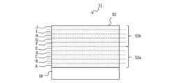
- FIG. 3 is a schematic cross-sectional view of a positive electrode that is another example of the embodiment.
- the positive electrode 11 includes a positive electrode current collector 50 and a positive electrode mixture layer 52 provided on the positive electrode current collector 50 .
- a foil of a metal such as aluminum that is stable in the potential range of the positive electrode 11, a film in which the metal is arranged on the surface layer, or the like can be used.
- the positive electrode mixture layer 52 contains a positive electrode active material and a binder.
- the positive electrode mixture layer 42 preferably further contains a conductive material.
- a positive electrode mixture slurry containing a positive electrode active material, a binder, a conductive material, etc. is applied onto the positive electrode current collector 50, dried to form a positive electrode mixture layer 52, and then rolled by a rolling roller or the like. , is produced by rolling the positive electrode mixture layer 52 .
- the details of the method for manufacturing the positive electrode mixture layer 52 will be described later.
- the positive electrode mixture layer 52 shown in FIG. 3 is divided into two equal parts in the thickness direction, the lower half on the positive electrode current collector 50 side is defined as a first region 52a, and the upper half on the surface side of the positive electrode mixture layer 52 is defined as a second region. 52b.
- the binder contained in the first region 52a and the second region 52b contains a binder having a PVDF skeleton
- ESA-MS method heat generated gas analysis method
- the binding property between the positive electrode active materials, the binding property with the conductive material, and the binding property between the positive electrode mixture layer 52 and the positive electrode current collector 50 are enhanced. It is assumed that even if the layer 52 expands and contracts, the conductive path of the first region 52a and the conductive path between the first region 52a and the positive electrode current collector 50 are less likely to be cut. As a result, it is believed that the increase in DC resistance due to repeated charging and discharging of the battery is suppressed.
- the method and conditions for the heat evolved gas analysis (EGA-MS) are the same as described above, and are omitted here. A manufacturing example of the positive electrode mixture layer 52 having T1 higher than T2 will be described later.
- Binders having a PVDF skeleton are, for example, polyvinylidene fluoride (PVDF) and copolymers containing units derived from vinylidene fluoride (VDF).
- the copolymer may be a block copolymer or a random copolymer.
- a binder having a PVDF skeleton may have a three-dimensional network structure.
- the three-dimensional network structure is as described above.
- a binder having a PVDF skeleton is crosslinked by a known technique such as addition of a crosslinking agent, heating, irradiation with ultraviolet rays or electron beams, etc., to form a three-dimensional network structure. may be formed.
- the cross-linking agent cross-linking monomer is as described above.
- the average molecular weight of the binder having a PVDF skeleton is, for example, 100,000 or more and 2,500,000 or less.
- said average molecular weight is a number average molecular weight (polystyrene conversion value) calculated
- the positive electrode mixture layer 52 may contain a binder other than the binder having the PVDF skeleton.
- Binders other than the binder having a PVDF skeleton include, for example, polytetrafluoroethylene (PTFE), polyethylene, polypropylene, polyacrylic acid, polymethyl acrylate, and ethylene-acrylic acid copolymer.
- the positive electrode mixture layer 52 shown in FIG. 3 is divided into 10 equal parts in the thickness direction, and the 10 equal parts are divided into A region, B region, C region, D region, E region, and F in order from the positive electrode current collector 50 side. area, G area, H area, I area, and J area.
- the binder contained in the A to J regions contains a binder having a PVDF skeleton, and the ratio of the F element derived from the binder contained in each region of the A region, the B region, and the C region is the highest.
- the ratio (W/V) of the ratio (W) of the F element, which is the highest among the ratios of the F element derived from the binder contained in each region of the D region, the E region, and the F region, to the ratio (V) of the F element is preferably less than 1.3.
- the W/V ratio is less than 1.3, the binder content in the regions A to C closer to the positive electrode current collector 50 is lower than when the W/V ratio is 1.3 or more.
- Examples of the positive electrode active material contained in the positive electrode mixture layer 52 include lithium composite oxides containing transition metal elements such as Co, Mn, and Ni.
- Lithium composite oxides include, for example, Ni, Co, Mn, Al, Zr, B, Mg, Sc, Y, Ti, Fe, Cu, Zn, Cr, Pb, Sn, Na, K, Ba, Sr, Ca, It may contain W, Mo, Nb, Si, or the like.
- the lithium composite oxide may be used singly or in combination of multiple kinds.
- the lithium composite oxide represented by the above general formula in general, the direct current resistance tends to increase due to repeated charging and discharging of the battery.
- the present embodiment has the effect of suppressing an increase in DC resistance due to repeated charging and discharging of the battery. It is possible to suppress an increase in DC resistance due to repeated charging and discharging.
- the conductive material contained in the positive electrode mixture layer 52 includes, for example, amorphous carbon (eg, carbon black, acetylene black, Ketjenblack, etc.), graphite, carbon-based materials such as carbon nanotubes, metal particles, and the like.
- amorphous carbon eg, carbon black, acetylene black, Ketjenblack, etc.
- graphite e.g., graphite
- carbon-based materials such as carbon nanotubes, metal particles, and the like.
- a positive electrode active material, a conductive material, a binder having a PVDF skeleton, and the like are mixed with a solvent to prepare a first positive electrode mixture slurry.
- a positive electrode active material, a conductive material, a binder having a PVDF skeleton, and the like are mixed together with a solvent (that is, a dispersant) to prepare a second positive electrode mixture slurry.
- the second positive electrode mixture slurry is applied to a predetermined thickness on the first positive electrode mixture slurry, By drying, the positive electrode mixture layer 52 is formed.
- T1 and T2 an example of a method for adjusting T1 and T2 described above will be described.
- a binder having a three-dimensional network structure and a PVFD skeleton is used for the first positive electrode mixture slurry
- a binder having a PVFD skeleton without a three-dimensional network structure is used for the second cathode mixture slurry.
- T1 mentioned above can be made higher than T2.
- T1 described above can be made higher than T2.
- the dried coating film is coated with the above-described first positive electrode mixture slurry.
- the two positive electrode mixture slurry may be applied to a predetermined thickness and dried.
- the second positive electrode mixture slurry is applied on the first positive electrode mixture slurry. is applied to a predetermined thickness and dried at the same time, it is easier to adjust the W/V to less than 1.3.
- the content of the positive electrode active material contained in the positive electrode mixture layer 52 is preferably, for example, 90% by mass or more with respect to the total mass of the positive electrode mixture layer 52 .
- the content of the conductive material contained in the positive electrode mixture layer 52 is preferably 1% by mass or more with respect to the total mass of the positive electrode mixture layer 52 .
- the content of the binder contained in the positive electrode mixture layer 52 is preferably 0.5 mass % or more with respect to the total mass of the positive electrode mixture layer 42 .
- the negative electrode 12 has a negative electrode current collector and a negative electrode mixture layer provided on the negative electrode current collector.
- the negative electrode current collector for example, a foil of a metal such as copper that is stable in the potential range of the negative electrode, a film having the metal on the surface layer, or the like is used.
- the negative electrode mixture layer preferably contains a negative electrode active material and further contains a binder, a conductive material, and the like.
- a negative electrode mixture slurry containing a negative electrode active material, a binder, etc. is prepared, this negative electrode mixture slurry is applied onto a negative electrode current collector, and dried to form a negative electrode mixture layer. It can be produced by rolling the negative electrode mixture layer.
- the negative electrode active material is not particularly limited as long as it is a material capable of intercalating and deintercalating lithium ions.
- Lithium alloys such as tin alloys, graphite, coke, carbon materials such as organic sintered bodies, metal oxides such as SnO 2 , SnO, TiO 2 and the like. These may be used singly or in combination of two or more.
- Binders include, for example, fluororesins such as polytetrafluoroethylene (PTFE) and polyvinylidene fluoride (PVdF), polyacrylonitrile (PAN), polyimide, acrylic resins, styrene-butadiene rubber (SBR), polyolefins, carboxymethylcellulose ( CMC) or cellulose derivatives such as salts thereof, polyethylene oxide (PEO), and the like.
- fluororesins such as polytetrafluoroethylene (PTFE) and polyvinylidene fluoride (PVdF), polyacrylonitrile (PAN), polyimide, acrylic resins, styrene-butadiene rubber (SBR), polyolefins, carboxymethylcellulose ( CMC) or cellulose derivatives such as salts thereof, polyethylene oxide (PEO), and the like.
- conductive material include materials similar to those of the positive electrode 11 .
- separator 13 for example, a porous sheet or the like having ion permeability and insulation is used. Specific examples of porous sheets include microporous thin films, woven fabrics, and non-woven fabrics. Suitable materials for the separator include olefin resins such as polyethylene and polypropylene, and cellulose.
- the separator 13 may be a laminate having a cellulose fiber layer and a thermoplastic resin fiber layer such as an olefin resin.
- a multilayer separator including a polyethylene layer and a polypropylene layer may be used, and a separator whose surface is coated with a material such as aramid resin or ceramic may be used.
- N - methyl- _ A positive electrode mixture slurry A was prepared by adding an appropriate amount of 2-pyrrolidone and stirring.
- the binder P used in the positive electrode mixture slurry A was produced as follows. First, a copolymer of vinylidene fluoride and hexafluoropropylene: PVDF-HFP (manufactured by Sigma-Aldrich, average molecular weight Mw 400000), trimethylhexamethylenediamine (manufactured by Tokyo Chemical Industry Co., Ltd.) as a cross-linking agent, and methyl isobutyl ketone. to obtain a mixed solution. A film was produced by casting the mixed solution (solution casting method). This film was heated at 110° C. to prepare a crosslinked fluorine-containing polymer (binder P). The amount of trimethylhexamethylenediamine added is 0.00 per 100 parts by mass of PVDF-HFP. 1 part by mass. The film-like binder P was pulverized into powder.
- PVDF-HFP manufactured by Sigma-Aldrich, average molecular weight Mw 400000
- trimethylhexamethylenediamine
- the average molecular weight of binder P was 1,000,000 or more.
- the average molecular weight is the number average molecular weight determined by gel permeation chromatography (GPC), as described above. Measurement of the average molecular weight is the same below.
- a lithium composite oxide represented by LiNi 0.8 Co 0.15 Al 0.05 O 2 , a binder Q, and a conductive material were mixed at a mass ratio of 100:1:1 to form a mixture, N- A positive electrode mixture slurry B was prepared by adding an appropriate amount of methyl-2-pyrrolidone and stirring.
- the binder Q used in the positive electrode mixture slurry B is a copolymer of vinylidene fluoride and hexafluoropropylene: PVDF-HFP (manufactured by Sigma-Aldrich).
- the average molecular weight of Binder Q was 400,000.
- the positive electrode mixture slurry B was applied on the positive electrode mixture slurry A and then dried to form a coating film. After that, by rolling the coating film with a rolling roller, a positive electrode having positive electrode mixture layers formed on both sides of the positive electrode current collector was produced.
- the coating thickness ratio of the positive electrode mixture slurry A and the positive electrode mixture slurry B was set to 50:50, and the basis weight of the positive electrode mixture layer was set to 200 g/m 2 .
- the basis weight of the positive electrode mixture layer is the same in other examples and comparative examples.
- the lower half on the positive electrode current collector side is the first region
- the upper half on the surface side of the positive electrode mixture layer is the second region, heating the first region
- the measurement method for heat generated gas analysis is as described above.
- the positive electrode mixture layer is divided into 10 equal parts in the thickness direction, and the 10 equal parts are divided into 10 equal parts in order from the positive electrode current collector side, A region, B region, C region, D region, E region, F region, G region,
- the proportion of the F element derived from the binder contained in each region of the A region, the B region, and the C region In the case of the H region, the I region, and the J region, the proportion of the F element derived from the binder contained in each region of the A region, the B region, and the C region.
- the ratio (W/V) of the highest ratio (W) of the F element among the ratios of the F element derived from the binder contained in each region of the region and the F region was 1.05.
- the method for measuring the ratio of the F element derived from the binder in each region is as described above.
- Graphite, CMC, and SBR were mixed at a mass ratio of 98:1:1, and the mixture was kneaded with water to prepare a negative electrode mixture slurry.
- This negative electrode mixture slurry was applied to both sides of a copper foil having a thickness of 8 ⁇ m, the coating film was dried, and then rolled with rolling rollers to form a negative electrode mixture layer on both sides of the negative electrode current collector. was made.
- EC ethylene carbonate
- MEC methyl ethyl carbonate
- Example 2 Except for changing the molecular weight of PVDF-HFP, which is the raw material of the binder P used in the positive electrode mixture slurry A, to 450,000, and changing the molecular weight of the binder Q used in the positive electrode mixture slurry B to 450,000, A positive electrode was produced in the same manner as in Example 1.
- the average molecular weight of Binder P used in Example 2 was 1000,000 or more, and the average molecular weight of Binder Q was 450,000.
- T1 in the produced positive electrode was 360° C.
- T2 was 300° C.
- the W/V ratio was 1.03.
- a secondary battery was produced in the same manner as in Example 1, except that this positive electrode was used.
- Example 3 After applying and drying the positive electrode mixture slurry A on both sides of a 15 ⁇ m thick aluminum foil, the positive electrode mixture slurry B is applied and dried on the coating film of the obtained positive electrode mixture slurry A to obtain a positive electrode mixture slurry.
- a positive electrode was produced in the same manner as in Example 2, except that the coating film of B was formed. T1 in the produced positive electrode was 360° C., T2 was 300° C., and the W/V ratio was 1.35.
- a secondary battery was produced in the same manner as in Example 1, except that this positive electrode was used.
- Example 1 The positive electrode mixture slurry A used in Example 2 was applied to both sides of an aluminum foil having a thickness of 15 ⁇ m, and then dried to form a coating film. After that, by rolling the coating film with a rolling roller, a positive electrode having positive electrode mixture layers formed on both sides of the positive electrode current collector was produced.
- the produced positive electrode had T1 of 360° C., T2 of 360° C., and a W/V ratio of 1.05.
- a secondary battery was produced in the same manner as in Example 1, except that this positive electrode was used.
- Example 2 The positive electrode mixture slurry B used in Example 2 was applied to both sides of an aluminum foil having a thickness of 15 ⁇ m, and then dried to form a coating film. After that, by rolling the coating film with a rolling roller, a positive electrode having positive electrode mixture layers formed on both sides of the positive electrode current collector was produced.
- the produced positive electrode had T1 of 300° C., T2 of 300° C., and a W/V ratio of 1.04.
- a secondary battery was produced in the same manner as in Example 1, except that this positive electrode was used.
- Example 3 After applying the positive electrode mixture slurry B used in Example 2 to both sides of an aluminum foil having a thickness of 15 ⁇ m, the positive electrode mixture slurry A used in Example 2 was applied onto the positive electrode mixture slurry B, and then dried. to form a coating film. After that, by rolling the coating film with a rolling roller, a positive electrode having positive electrode mixture layers formed on both sides of the positive electrode current collector was produced.
- the coating thickness ratio of the positive electrode mixture slurry A and the positive electrode mixture slurry B was set to 50:50.
- the positive electrode thus prepared had T1 of 300°C, T2 of 360°C, and a W/V ratio of 1.05.
- a secondary battery was produced in the same manner as in Example 1, except that this positive electrode was used.
- the secondary batteries of each example and each comparative example were charged at a constant current of 0.5C until the voltage reached 4.3V, and then charged at a constant voltage until the voltage reached 0.05C. After that, the battery was discharged at a constant current of 0.5C until the battery voltage reached 2.5V. This charging/discharging was regarded as one cycle, and 100 cycles were performed. Then, in an environment of 25 ° C., the secondary batteries of each example and each comparative example were discharged at a constant current of 0.5 C until the voltage reached 3.0 V, and then the DC resistance was measured by the same method as described above. asked for This is defined as the DC resistance after charge/discharge cycles.
- the DC resistance increase rate was obtained by applying the initial DC resistance and the DC resistance after the charge/discharge cycles to the following formula.
- DC resistance increase rate (DC resistance after charge/discharge cycle/initial DC resistance) x 100
- Table 1 shows the DC resistance increase rates of other examples and comparative examples relative to the resistance increase rate of Comparative Example 1 (100%).
- the positive electrode mixture layer is divided into 10 equal parts in the thickness direction, and the 10 equal parts are divided into A region, B region, C region, D region, E region, F region, G region, in order from the positive electrode current collector side.
- the ratio of F element (V) which is the highest among the ratios of F element derived from the binder contained in each region of A region, B region, and C region, D region.
Landscapes
- Chemical & Material Sciences (AREA)
- Chemical Kinetics & Catalysis (AREA)
- Electrochemistry (AREA)
- General Chemical & Material Sciences (AREA)
- Engineering & Computer Science (AREA)
- Materials Engineering (AREA)
- Inorganic Chemistry (AREA)
- Battery Electrode And Active Subsutance (AREA)
Priority Applications (3)
| Application Number | Priority Date | Filing Date | Title |
|---|---|---|---|
| US18/832,224 US20250149540A1 (en) | 2022-01-26 | 2023-01-19 | Positive electrode for secondary battery, and secondary battery |
| JP2023576843A JPWO2023145591A1 (https=) | 2022-01-26 | 2023-01-19 | |
| CN202380018390.2A CN118591900A (zh) | 2022-01-26 | 2023-01-19 | 二次电池用正极和二次电池 |
Applications Claiming Priority (2)
| Application Number | Priority Date | Filing Date | Title |
|---|---|---|---|
| JP2022010209 | 2022-01-26 | ||
| JP2022-010209 | 2022-01-26 |
Publications (1)
| Publication Number | Publication Date |
|---|---|
| WO2023145591A1 true WO2023145591A1 (ja) | 2023-08-03 |
Family
ID=87471812
Family Applications (1)
| Application Number | Title | Priority Date | Filing Date |
|---|---|---|---|
| PCT/JP2023/001459 Ceased WO2023145591A1 (ja) | 2022-01-26 | 2023-01-19 | 二次電池用正極及び二次電池 |
Country Status (4)
| Country | Link |
|---|---|
| US (1) | US20250149540A1 (https=) |
| JP (1) | JPWO2023145591A1 (https=) |
| CN (1) | CN118591900A (https=) |
| WO (1) | WO2023145591A1 (https=) |
Cited By (2)
| Publication number | Priority date | Publication date | Assignee | Title |
|---|---|---|---|---|
| WO2025196892A1 (ja) * | 2024-03-18 | 2025-09-25 | 株式会社 東芝 | 電極、電池及び電池パック |
| WO2025249898A1 (ko) * | 2024-05-29 | 2025-12-04 | 삼성에스디아이 주식회사 | 이차 전지 |
Citations (2)
| Publication number | Priority date | Publication date | Assignee | Title |
|---|---|---|---|---|
| JPH09185960A (ja) * | 1995-12-28 | 1997-07-15 | Dainippon Printing Co Ltd | 非水電解液二次電池用電極板及びその製造方法 |
| JPH1167214A (ja) * | 1997-08-21 | 1999-03-09 | Ricoh Co Ltd | リチウム二次電池 |
-
2023
- 2023-01-19 JP JP2023576843A patent/JPWO2023145591A1/ja active Pending
- 2023-01-19 WO PCT/JP2023/001459 patent/WO2023145591A1/ja not_active Ceased
- 2023-01-19 CN CN202380018390.2A patent/CN118591900A/zh active Pending
- 2023-01-19 US US18/832,224 patent/US20250149540A1/en active Pending
Patent Citations (2)
| Publication number | Priority date | Publication date | Assignee | Title |
|---|---|---|---|---|
| JPH09185960A (ja) * | 1995-12-28 | 1997-07-15 | Dainippon Printing Co Ltd | 非水電解液二次電池用電極板及びその製造方法 |
| JPH1167214A (ja) * | 1997-08-21 | 1999-03-09 | Ricoh Co Ltd | リチウム二次電池 |
Cited By (2)
| Publication number | Priority date | Publication date | Assignee | Title |
|---|---|---|---|---|
| WO2025196892A1 (ja) * | 2024-03-18 | 2025-09-25 | 株式会社 東芝 | 電極、電池及び電池パック |
| WO2025249898A1 (ko) * | 2024-05-29 | 2025-12-04 | 삼성에스디아이 주식회사 | 이차 전지 |
Also Published As
| Publication number | Publication date |
|---|---|
| CN118591900A (zh) | 2024-09-03 |
| JPWO2023145591A1 (https=) | 2023-08-03 |
| US20250149540A1 (en) | 2025-05-08 |
Similar Documents
| Publication | Publication Date | Title |
|---|---|---|
| US10923707B2 (en) | Dry process method for producing electrodes for electrochemical devices and electrodes for electrochemical devices | |
| KR102005870B1 (ko) | 이차 전지용 세퍼레이터 및 이를 포함하는 리튬 이차 전지 | |
| US9350006B2 (en) | Electrode assembly and electrochemical device including the same | |
| KR102407049B1 (ko) | 이차 전지용 바인더, 이를 포함하는 이차 전지용 세퍼레이터 및 이를 포함하는 이차 전지 | |
| US9484599B2 (en) | Non-aqueous electrolyte secondary battery | |
| JP6362125B2 (ja) | 二種のバインダーを含む正極活物質スラリー及びこれから製造された正極 | |
| WO2003088404A1 (fr) | Accumulateur d'electrolyte non aqueux | |
| JPWO2018207530A1 (ja) | 非水電解質二次電池 | |
| JP2004079327A (ja) | 非水二次電池および非水二次電池用正極とその製造方法 | |
| WO2023145591A1 (ja) | 二次電池用正極及び二次電池 | |
| JP4432244B2 (ja) | 平板積層型電池 | |
| JPWO2017047653A1 (ja) | 非水二次電池用電極、その製造方法、および非水二次電池 | |
| JP6843580B2 (ja) | リチウムイオン電池の製造方法 | |
| CN116250100A (zh) | 非水电解质二次电池用正极和非水电解质二次电池 | |
| KR20220124918A (ko) | 댐 라인 코팅층의 형성을 포함하는 전극의 제조방법 | |
| JP4942249B2 (ja) | リチウムイオン二次電池の製造方法 | |
| KR101985260B1 (ko) | 다중 그물구조 고분자 분리막 및 이를 포함하는 이차전지 | |
| JPH10112321A (ja) | 非水電解液二次電池およびその製造方法 | |
| EP4564577A1 (en) | Nonaqueous electrolyte secondary battery | |
| JPWO2020175362A1 (ja) | 非水電解質二次電池電極用スラリー、非水電解質二次電池電極用スラリーの製造方法、非水電解質二次電池用電極及び非水電解質二次電池 | |
| KR20180017453A (ko) | 리튬 이차전지용 음극 및 이를 포함하는 리튬 이차전지 | |
| JPH1021963A (ja) | 電池およびその製造方法 | |
| WO2024024746A1 (ja) | 非水電解質二次電池用正極及び非水電解質二次電池 | |
| KR101684589B1 (ko) | 양극 활물질 2차 입자 및 그를 포함하는 리튬 이차전지 | |
| US20250149590A1 (en) | Nonaqueous electrolyte secondary battery positive electrode and nonaqueous electrolyte secondary battery |
Legal Events
| Date | Code | Title | Description |
|---|---|---|---|
| 121 | Ep: the epo has been informed by wipo that ep was designated in this application |
Ref document number: 23746804 Country of ref document: EP Kind code of ref document: A1 |
|
| ENP | Entry into the national phase |
Ref document number: 2023576843 Country of ref document: JP Kind code of ref document: A |
|
| WWE | Wipo information: entry into national phase |
Ref document number: 18832224 Country of ref document: US Ref document number: 202380018390.2 Country of ref document: CN |
|
| NENP | Non-entry into the national phase |
Ref country code: DE |
|
| 122 | Ep: pct application non-entry in european phase |
Ref document number: 23746804 Country of ref document: EP Kind code of ref document: A1 |
|
| WWP | Wipo information: published in national office |
Ref document number: 18832224 Country of ref document: US |