WO2023144930A1 - ワイヤハーネスの取付構造 - Google Patents
ワイヤハーネスの取付構造 Download PDFInfo
- Publication number
- WO2023144930A1 WO2023144930A1 PCT/JP2022/002897 JP2022002897W WO2023144930A1 WO 2023144930 A1 WO2023144930 A1 WO 2023144930A1 JP 2022002897 W JP2022002897 W JP 2022002897W WO 2023144930 A1 WO2023144930 A1 WO 2023144930A1
- Authority
- WO
- WIPO (PCT)
- Prior art keywords
- wire harness
- inverter device
- vehicle
- battery unit
- drive unit
- Prior art date
Links
Images


Classifications
-
- B—PERFORMING OPERATIONS; TRANSPORTING
- B60—VEHICLES IN GENERAL
- B60K—ARRANGEMENT OR MOUNTING OF PROPULSION UNITS OR OF TRANSMISSIONS IN VEHICLES; ARRANGEMENT OR MOUNTING OF PLURAL DIVERSE PRIME-MOVERS IN VEHICLES; AUXILIARY DRIVES FOR VEHICLES; INSTRUMENTATION OR DASHBOARDS FOR VEHICLES; ARRANGEMENTS IN CONNECTION WITH COOLING, AIR INTAKE, GAS EXHAUST OR FUEL SUPPLY OF PROPULSION UNITS IN VEHICLES
- B60K1/00—Arrangement or mounting of electrical propulsion units
- B60K1/04—Arrangement or mounting of electrical propulsion units of the electric storage means for propulsion
-
- B—PERFORMING OPERATIONS; TRANSPORTING
- B60—VEHICLES IN GENERAL
- B60R—VEHICLES, VEHICLE FITTINGS, OR VEHICLE PARTS, NOT OTHERWISE PROVIDED FOR
- B60R16/00—Electric or fluid circuits specially adapted for vehicles and not otherwise provided for; Arrangement of elements of electric or fluid circuits specially adapted for vehicles and not otherwise provided for
- B60R16/02—Electric or fluid circuits specially adapted for vehicles and not otherwise provided for; Arrangement of elements of electric or fluid circuits specially adapted for vehicles and not otherwise provided for electric constitutive elements
-
- Y—GENERAL TAGGING OF NEW TECHNOLOGICAL DEVELOPMENTS; GENERAL TAGGING OF CROSS-SECTIONAL TECHNOLOGIES SPANNING OVER SEVERAL SECTIONS OF THE IPC; TECHNICAL SUBJECTS COVERED BY FORMER USPC CROSS-REFERENCE ART COLLECTIONS [XRACs] AND DIGESTS
- Y02—TECHNOLOGIES OR APPLICATIONS FOR MITIGATION OR ADAPTATION AGAINST CLIMATE CHANGE
- Y02T—CLIMATE CHANGE MITIGATION TECHNOLOGIES RELATED TO TRANSPORTATION
- Y02T10/00—Road transport of goods or passengers
- Y02T10/60—Other road transportation technologies with climate change mitigation effect
- Y02T10/72—Electric energy management in electromobility
Definitions
- the present invention relates to a wire harness mounting structure.
- An electric vehicle runs by converting electric power supplied from a battery into electric power suitable for driving a drive motor using an inverter device, and driving the drive motor.
- JP5589772B a power unit (driving motor) and an inverter device are arranged in a motor room, and this inverter device and a main battery arranged under the floor of the vehicle are connected to a power cable (wire) routed in the longitudinal direction of the vehicle.
- An electric vehicle connected via a harness is disclosed.
- the wire harness that connects the main battery and the inverter device is routed in the longitudinal direction of the vehicle.
- due to factors such as an increase in the size of the battery it is difficult to form an extra space in the front-rear direction of the vehicle. For this reason, it is not easy to provide a sufficient length of the harness in the longitudinal direction of the vehicle, and it is difficult to take countermeasures against swinging of the drive unit.
- the present invention has been made in view of such problems, and it is an object of the present invention to provide a wiring harness mounting structure capable of increasing the length of the wire harness particularly on the rear side of a vehicle where there is little space. With the goal.
- a wire harness mounting structure for a vehicle including a drive unit that drives the vehicle and a battery unit that supplies power to the drive unit via a wire harness.
- the battery unit is arranged on the floor between the front and rear wheels of the vehicle.
- the drive unit is arranged on the rear side of the vehicle relative to the battery unit, and includes a drive motor that drives the drive wheels, and an inverter device that converts the power of the battery unit and supplies the converted power to the drive motor.
- the wire harness has one end connected to the inverter device in the vehicle width direction at the side portion of the inverter device, and the other end connected to the battery unit in the vehicle width direction at the rear end portion of the battery unit.
- the wire harness is connected to the inverter device and the battery unit in the vehicle width direction. Accordingly, even if the drive unit and the battery unit are arranged close to each other, the wire harness can be routed in the lateral direction in the gap between the drive unit and the battery unit. Furthermore, since the harness length of the wire harness can be given a margin in the lateral direction, the stress of the wire harness when the drive unit swings can be alleviated.
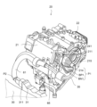
- FIG. 1 is an explanatory diagram of a drive unit according to an embodiment of the invention.
- FIG. 2 is an explanatory diagram of an electric vehicle on which the drive unit is mounted.
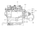
- FIG. 3 is an explanatory diagram of the drive unit.
- FIG. 4 is an explanatory diagram of the drive unit.
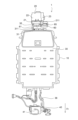
- FIG. 5 is a cross-sectional view of the electric vehicle.
- FIG. 1 is an explanatory diagram of the rear drive unit 20 of this embodiment.
- FIG. 2 is an explanatory diagram of the entire drive system of the electric vehicle 1 in which the rear drive unit 20 according to the embodiment of the invention is mounted.
- An electric vehicle 1 (hereinafter referred to as vehicle 1) is configured by mounting a rear drive unit 20, a battery unit 30, and a front drive unit 40 on a vehicle body 10, as shown in FIG.
- the rear drive unit 20 is arranged behind the battery unit 30 in the vehicle.
- a wire harness 35 for supplying DC power from the battery unit 30 is connected to the rear drive unit 20 .
- the rear drive unit 20 is configured with an inverter device 21, a drive motor 22 and a speed reducer 23.
- a cooling water pipe 26 through which cooling water flows is connected to the rear drive unit 20 .
- the rear drive unit 20 drives the vehicle 1 by driving the drive motor 22 based on the electric power from the battery unit 30, thereby rotating the axle 23a and the rear wheels 15 (see FIG. 5) that are drive wheels. .
- a drive motor 22 and a speed reducer 23 are arranged in the vehicle width direction with their rotation shafts parallel to each other.
- the inverter device 21 is arranged above the drive motor 22 and the speed reducer 23 so as to be inclined toward the front side of the vehicle 1 .
- the inverter device 21 includes an inverter (not shown) that converts electric power supplied from the battery unit 30 into electric power suitable for driving the drive motor 22 and supplies the electric power to the drive motor 22 .
- the inverter is accommodated in a housing 24 that is a metal or resin enclosure.
- the inverter device 21 receives power supply from the battery unit 30 to drive the drive motor 22 . Further, the inverter device 21 receives regenerated electric power from the drive motor 22 and charges the battery unit 30 .
- the drive motor 22 is composed of a rotating electric machine such as a permanent magnet embedded synchronous motor or a field winding synchronous motor.
- the speed reducer 23 is configured with a plurality of gears that reduce the speed of rotation of the drive motor 22 and transmit it to the axle.
- the speed reducer 23 may be configured as a transmission capable of stepwise or steplessly switching a plurality of gear stages.
- the battery unit 30 is arranged on the floor between the front and rear wheels of the vehicle 1, as shown in FIG.
- the battery unit 30 is configured with a plurality of battery modules inside.
- a wire harness 35 for supplying electric power is connected to the inverter device 21 and the battery unit 30 .
- the wire harness 35 is composed of a pair of positive and negative conductor wires, which are made of copper, aluminum, or the like and are coated with insulation.
- the wire harness 35 is covered with a protector 60 and a cushioning material 61 .
- the wire harness 35 has terminals connected to the inverter device 21 and the battery unit 30 at both ends thereof. .
- a front drive unit 40 that drives the front wheels is provided on the front side (motor room) of the vehicle 1, as shown in FIG.
- the front drive unit 40 includes a front drive motor (not shown) and a front inverter device 41 that supplies power to the front drive motor.
- a front wire harness 36 for supplying electric power is connected between the front inverter device 41 of the front drive unit 40 and the battery unit 30 .
- vehicle 1 of this embodiment does not necessarily have to include the front drive unit 40 .
- vehicle 1 may be configured such that only the rear wheels 15 are driven by the rear drive unit 20 .
- the rear drive unit 20 arranged on the rear side of the vehicle has the battery unit 30 arranged on the front side thereof, and the structure of the vehicle body 10 such as the luggage compartment exists on the upper side thereof. height is lower. Due to this structure, the space between the rear drive unit 20 and the battery unit 30 does not have enough margin. Furthermore, since the wire harness is composed of thick wires so that the voltage of the battery unit 30 (for example, 400 V DC) can flow, the degree of freedom in bending and elasticity are low. For this reason, conventionally, there has been a problem that it is difficult to give the wire harness a sufficient length.
- the wire harness 35 is configured to have a marginal length to address such a problem.
- one end of the wire harness 35 is connected to an inverter-side connector 211 provided on the side surface of the inverter device 21 , and the other end is arranged so as to protrude from the rear end side of the battery unit 30 . It is connected to a battery side connector 311 provided in the connecting portion 31 connected to the battery.
- One end of the wire harness 35 is configured as the one end side connection terminal P1, and the other end is configured as the other end side connection terminal P2.
- the housing 24 of the inverter device 21 is provided with an opening 241 to which the one-end connection terminal P1, which will be described in detail in FIG. 3, is fixed, and a cover 242 that closes the opening.
- the inverter-side connector 211 is provided on the left side of the inverter device 21 in the vehicle front-rear direction, and is connected to one end-side connection terminal P1 of the wire harness 35 .
- the battery-side connector 311 is provided on the right side in the vehicle front-rear direction of the connecting portion 31 projecting from the rear end side of the battery unit 30 .
- the other end side connection terminal P2 of the wire harness 35 is connected to the battery side connector 311 .
- the wire harness 35 extends in the vehicle width direction from the inverter-side connector 211 on the left side surface of the inverter device 21, and then bends 180 degrees toward the right side in the vehicle width direction.
- the wire harness 35 is routed from the left side to the right side in the vehicle width direction between the inverter device 21 and the battery unit 30, and is turned 180° toward the left side in the vehicle width direction near the right side surface of the inverter device 21. flex.
- the wire harness 35 extends to a battery-side connector 311 arranged on the right side surface of the connection portion 31 of the battery unit 30 .
- one end of the wire harness 35 is connected to the inverter side connector 211 provided on the left side surface of the inverter device 21 from the left side to the right side (first direction) in the vehicle width direction, and the other end is connected to the battery unit. It is connected to the battery side connector 311 provided on the right side surface of the connecting portion 31 of 30 from the right side toward the left side (second direction) in the vehicle width direction.
- the wire harness 35 is routed in the vehicle width direction, and is formed in an S shape (Z shape) bent at about 180° when viewed from above.
- one end of the wire harness 36 is connected to a connector provided on the left side surface of the front inverter device 41 from left to right (second direction) in the vehicle width direction. be done.
- the wire harness 35 is covered with a U-shaped hard resin protector 60 near the inverter-side connector 211 so as to cover the outer periphery thereof.
- the protector 60 is supported by the housing 24 of the inverter device 21 with a predetermined distance from the inverter device 21 by means of an L-shaped bracket 65 .
- the bracket 65 has a housing fixing portion that is fixed to the surface of the housing 24 by bolting, and a protector fixing portion that extends toward the protector 60 and is fixed to the rear surface of the protector 60 by bolting.
- the housing fixing portion and the protector fixing portion are formed in a crank shape in the vehicle front-rear direction.
- a buffer material 61 made of soft resin is wrapped around the battery-side connector 311 of the wire harness 35 .
- the wire harness 35 is restricted from swinging near the inverter device 21 by the protector 60 and the bracket 65 while maintaining a predetermined distance from the inverter device 21 .
- stress due to excessive vibration of the wire harness 35 is suppressed, and the durability of the wire harness 35 is improved.
- the soft cushioning material 61 allows the wire harness 35 to swing, and suppresses the wire harness 35 from buffering with other members.
- the wire harness 35 can have a margin in the vehicle width direction while arranging the rear drive unit 20 closer to the battery unit 30 .
- the wire harness 35 is configured to be able to swing, the relative swing between the rear drive unit 20 and the vehicle body 10 to which the battery unit 30 is fixed is allowed, and is applied to the wire harness 35. Can relieve stress.
- FIG. 3 and 4 are explanatory diagrams of the inverter device 21 of this embodiment, and are diagrams for explaining the inverter-side connector 211.
- FIG. 3 shows a perspective view of the inverter device 21
- FIG. 4 shows a front view of the inverter device 21 as viewed from the front side of the vehicle.
- 3 and 4 both show a state in which the protector 60 of the wire harness 35 and the cover 242 of the inverter-side connector 211 are removed. Also, the speed reducer 23 is omitted.
- An insertion hole 215 into which the one-end connection terminal P1 is inserted is formed on the side surface of the inverter device 21 .
- An opening 241 is formed on the front side of the inverter device 21 for bolting with the one-end-side connection terminal P1 inserted therein.
- a terminal (not shown) is provided inside the opening 241, and the one end side connection terminal P1 is fixed to this terminal.
- a plate-shaped positive electrode terminal BP1 connected to the positive electrode side conductor wire and a plate-shaped negative electrode terminal BN1 fixed to the negative electrode side conductor wire are provided.
- Each terminal is formed with a bolt hole for fixing a bolt.
- a boot 214 fixed to the insertion hole 215 is provided on the one end side connection terminal P ⁇ b>1 of the wire harness 35 .
- the inverter-side connector 211 and the one-end-side connection terminal P1 configured in this way are assembled as follows. First, the positive terminal BP1 and the negative terminal BN1 constituting the one end side connection terminal P1 of the wire harness 35 are inserted through the insertion hole 215 opened in the side surface of the housing 24 . The positive terminal BP1 and the negative terminal BN1 are fixed to terminals on the inverter device 21 side through the opening 241 by bolting. After the positive terminal BP1 and the negative terminal BN1 are fixed, the opening 241 is closed by the cover 242 . A boot 214 attached to one end of the wire harness 35 is fixed to the insertion hole 215 by bolting.
- the one-end connection terminal P1 is fixed to the inverter-side connector 211.
- the other end side of the wire harness 35 is constituted by the other end side connection terminal P2, which is a one-touch connector that can be inserted into and removed from the connection portion 31 of the battery unit 30, as shown in FIG.
- the other end side connection terminal P2 is locked by being inserted into the battery side connector 311 .
- the operator when removing the rear drive unit 20 from the vehicle body 10 during maintenance of the vehicle 1, first, the operator removes the other end side connection terminal P2 from the battery side connector 311 on the battery unit 30 side. Since the other end side connection terminal P2 is a one-touch connector, it can be easily attached and detached by a predetermined procedure. The rear drive unit 20 is removed from the vehicle body 10 with the wire harness 35 connected.
- FIG. 5 is a vertical cross-sectional view of the vehicle 1 in the front-rear direction centering on the rear drive unit 20 of this embodiment.
- the rear drive unit 20 is arranged under the floor on the rear side of the vehicle body 10 via a suspension member 102 fixed to the vehicle body 10 .
- a cross member 101 is arranged on the vehicle body 10 so as to traverse the vehicle body 10 in the width direction.
- the rear drive unit 20 is arranged adjacent to the cross member 101 on the rear side of the cross member 101 .
- Battery unit 30 is fixed to the underfloor portion of vehicle body 10 on the front side of cross member 101 .
- the wire harness 35 described above is routed between the rear drive unit 20 and the battery unit 30 .
- a protector 60 is attached to the wiring harness 35 near the inverter device 21 .
- Protector 60 is fixed to the outside of housing 24 of inverter device 21 by bracket 65 .
- the wire harness 35 may be caught between the housing 24 of the inverter device 21 and the cross member 101 .
- the fixing positions of the bracket 65 for fixing the protector 60 that is, the housing fixing portion fixed to the housing 24 and the protector fixing portion fixed to the protector 60 are arranged at a height above the ground of the cross member 101. (the bottom surface of the cross member 101 indicated by the dashed line in FIG. 5).
- the vehicle 1 includes the drive unit (rear drive unit 20) and the battery unit 30 that supplies power to the rear drive unit 20 via the wire harness 35.
- the battery unit 30 is arranged on the floor surface between the front wheels and the rear wheels of the vehicle 1
- the rear drive unit 20 is arranged on the rear side of the vehicle 1 relative to the battery unit 30 .
- the rear drive unit 20 includes a drive motor 22 that drives the rear wheels 15 that are drive wheels, and an inverter device 21 that converts the power of the battery unit 30 and supplies the converted power to the drive motor 22 .
- One end of the wire harness 35 is connected to the inverter device 21 in the vehicle width direction at the side portion of the inverter device 21, and the other end is connected to the battery unit 30 in the vehicle width direction at the rear end portion of the battery unit 30. be done.
- the wire harness 35 is connected to the inverter device 21 and the battery unit 30 in the vehicle width direction.
- the wire harness 35 can be routed in the lateral direction of the vehicle 1 .
- the harness length of the wire harness 35 between the inverter device 21 and the battery unit 30 can have a margin in the lateral direction, the stress applied to the wire harness 35 when the rear drive unit 20 swings. can be mitigated.
- one end of the wire harness 35 is connected to the inverter device 21 from the left side to the right side (first direction) in the vehicle width direction via the inverter side connector 211, and the other end is connected to the battery side. It is connected to the battery unit 30 via the connector 311 from the right side to the left side (second direction) in the vehicle width direction opposite to the first direction.
- the wire harness 35 is routed while being bent in an S shape between the first direction and the second direction. can be routed in the lateral direction, and the harness length of the wire harness 35 can be given a margin.
- the inverter-side connector 211 fixes the wire harness 35 to the inverter device 21 by bolting
- the battery-side connector 311 is configured by a detachable one-touch connector.
- the rear drive unit 20 can be removed from the vehicle body 10 together with the wire harness 35 by removing the battery-side connector 311 that is easily attached and detached during maintenance.
- the front side of the vehicle 1 is provided with a front drive unit 40 having a front inverter device 41 and a front wire harness 36 that supplies electric power from the battery unit 30 to the front inverter device 41 .
- the front wire harness 36 has one end connected to the battery unit 30 and the other end connected to the front inverter device 41 from left to right (first direction) in the vehicle width direction.
- the inverter device 21 arranged on the rear wheel side and the front inverter device 41 on the front wheel side are connected to the wire harnesses 35 and 36 from the same first direction, they are arranged on the rear side.
- the inverter device 21 and the front inverter device 41 can have the same connectors and internal configurations. This eliminates the need to use different parts for the inverter device 21 and the front inverter device 41, thereby reducing the manufacturing cost.
- the wire harness 35 is fitted with a protector 60 that restricts rocking near one end thereof, that is, near the inverter-side connector 211 of the inverter device 21 .
- the soft cushioning material 61 prevents the wire harness 35 from buffering with other members while allowing rocking motion.
- the rear drive unit 20 is provided behind the cross member 101 adjacent to the cross member 101 that crosses the underfloor of the vehicle 1 in the vehicle width direction, and the protector 60 is connected to the inverter by the bracket 65 . It is fixed to the housing 24 of the device 21 , and the fixing position between the bracket 65 and the housing 24 is between the cross member 101 and the inverter device 21 and below the cross member 101 .
Landscapes
- Engineering & Computer Science (AREA)
- Mechanical Engineering (AREA)
- Chemical & Material Sciences (AREA)
- Combustion & Propulsion (AREA)
- Transportation (AREA)
- Arrangement Or Mounting Of Propulsion Units For Vehicles (AREA)
Abstract
車両を駆動する駆動ユニットと、ワイヤハーネスを介して駆動ユニットに電力を供給するバッテリユニットと、を備える車両における、ワイヤハーネスの取付構造である。バッテリユニットは、車両の前輪と後輪との間の床面に配置される。駆動ユニットは、バッテリユニットよりも車両進行方向の後側に、車両の後輪付近に配置されて、後輪を駆動するように構成される。駆動ユニットには、バッテリユニットの電力を変換するインバータ装置が備えられる。ワイヤハーネスは、その一端が、インバータ装置の側面部で、車幅方向からインバータ装置に連結され、その他端が、バッテリユニットの後端部で、車幅方向からバッテリユニットに連結される。
Description
本発明は、ワイヤハーネスの取付構造に関する。
電動車両は、バッテリから供給される電力をインバータ装置により駆動モータの駆動に適した電力に変換して、駆動モータを駆動することで走行する。
JP5589772Bには、モータルーム内にパワーユニット(駆動モータ)とインバータ装置とが配置され、このインバータ装置と車両の床下に配置された主バッテリとが、車両の前後方向に配索された電力ケーブル(ワイヤハーネス)を介して接続される電動車両が開示されている。
近年は、車両の航続距離を伸ばすためバッテリは大型化する傾向にあり、車両の前輪と後輪との間の床下部分の全体にバッテリユニットが配置されるように構成されている。このような構成では、特に後輪付近ではレイアウト空間に余裕が少ないため、駆動モータ、インバータ装置及びハーネスの配置に工夫が必要となる。さらに、駆動モータの揺動対策のため、ハーネス長に余裕を持たせておくことも要求される。
上述の特許文献では、主バッテリとインバータ装置とを接続するワイヤハーネスが車両の前後方向に配索されている。しかしながら、バッテリの大型化等の要因により、車両の前後方向には余裕スペースが形成されにくい。このため、車両前後方向にハーネス長の余裕を持たせることが容易でなく、駆動ユニットの揺動対策が難しいという問題がある。
本発明はこのような問題に鑑みてなされたものであり、特に空間に余裕が少ない車両後方側において、ワイヤハーネスの長さに余裕を持たせることが可能なワイヤハーネスの取付構造を提供することを目的とする。
本発明の一実施態様によれば、車両を駆動する駆動ユニットと、ワイヤハーネスを介して前記駆動ユニットに電力を供給するバッテリユニットと、を備える車両における、ワイヤハーネスの取付構造が提供される。バッテリユニットは、車両の前輪と後輪との間の床面に配置される。駆動ユニットは、バッテリユニットよりも車両の後側に配置されて、駆動輪を駆動する駆動モータと、バッテリユニットの電力を変換して駆動モータに供給するインバータ装置と、を備える。ワイヤハーネスは、その一端が、インバータ装置の側面部で、車幅方向からインバータ装置に連結され、その他端が、バッテリユニットの後端部で、車幅方向からバッテリユニットに連結される。
本発明によれば、ワイヤハーネスが、インバータ装置とバッテリユニットとに、それぞれ車幅方向に連結される。これにより、駆動ユニットとバッテリユニットとを近づけて配置させても、ワイヤハーネスを駆動ユニットとバッテリユニットとの隙間に横方向に配索させることができる。さらに、ワイヤハーネスのハーネス長を横方向に余裕を持たせることができるようになるので、駆動ユニットが揺動した際のワイヤハーネスの応力を緩和できる。
以下、図面等を参照して、本発明の実施形態について説明する。
図1は、本実施形態の後側駆動ユニット20の説明図である。図2は、本発明の実施形態に係る後側駆動ユニット20が搭載される電動車両1の駆動系全体の説明図である。
電動車両1(以下、車両1)は、図2に示すように、後側駆動ユニット20、バッテリユニット30、前側駆動ユニット40が、車体10に搭載されて構成される。
後側駆動ユニット20は、バッテリユニット30よりも車両後方に配置される。後側駆動ユニット20には、バッテリユニット30の直流電力が供給されるためのワイヤハーネス35が接続される。
図1に示すように、後側駆動ユニット20は、インバータ装置21、駆動モータ22及び減速機23を備えて構成される。後側駆動ユニット20には、冷却水が流通する冷却水配管26が接続される。後側駆動ユニット20は、バッテリユニット30からの電力に基づいて駆動モータ22を駆動することで、車軸23a及び駆動輪である後輪15(図5参照)を回転させて、車両1を駆動させる。
後側駆動ユニット20は、駆動モータ22と減速機23とが、それぞれ回転軸を並列に、車幅方向に配置される。インバータ装置21は、駆動モータ22及び減速機23の上側に、車両1の前側に傾斜して配置される。
インバータ装置21は、バッテリユニット30から供給された電力を駆動モータ22の駆動に適切な電力に変換して駆動モータ22に供給するインバータ(図示せず)を備える。インバータは、金属製又は樹脂製の筐体であるハウジング24に収容される。インバータ装置21は、バッテリユニット30の電力の供給を受けて駆動モータ22を駆動する。また、インバータ装置21は、駆動モータ22の回生電力を受けてバッテリユニット30を充電する。
駆動モータ22は、永久磁石埋込型同期電動機又は界磁巻線型同期電動機等の回転電機により構成される。
減速機23は、駆動モータ22の回転を減速して車軸に伝達する複数のギアを備えて構成される。減速機23は、複数の変速段を段階的又は無段階に切り替え可能な変速機として構成されていてもよい。
バッテリユニット30は、図2に示すように、車両1の前輪と後輪との間の床面に配置される。バッテリユニット30は、その内部に複数のバッテリモジュールを有して構成される。インバータ装置21とバッテリユニット30とには、電力を供給するワイヤハーネス35が接続される。
ワイヤハーネス35は、銅やアルミニウム等からなる導体に絶縁被覆を施した正負一組の導線により構成される。ワイヤハーネス35には、プロテクタ60及び緩衝材61が外装される。ワイヤハーネス35は、その両端にインバータ装置21とバッテリユニット30とに接続する端子をそれぞれ備え、これら端子間で車幅方向に配策され、上面視においてS字状に湾曲して配索される。
車両1の前方側(モータルーム)には、図2に示すように、前輪を駆動する前側駆動ユニット40が備えられる。前側駆動ユニット40は、後側駆動ユニット20と同様に、図示しない前側駆動モータと前側駆動モータに電力を供給する前側インバータ装置41とを備える。前側駆動ユニット40の前側インバータ装置41とバッテリユニット30との間には、電力を供給するための前側ワイヤハーネス36が接続される。
なお、本実施形態の車両1は、必ずしも前側駆動ユニット40を備えていなくてもよい。車両1が、後側駆動ユニット20によって後輪15のみを駆動するように構成されていてもよい。
次に、後側駆動ユニット20とバッテリユニット30との間に配索されるワイヤハーネス35について説明する。
車両1が走行するとき、路面からサスペンション等を介して入力される振動や、後側駆動ユニット20自身の振動等により、後側駆動ユニット20は、車体10に固定されたバッテリユニット30に対して相対的に揺動する。これらの間に接続されるワイヤハーネスが、後側駆動ユニット20の揺動による応力によって変形及び損傷することを防止するため、揺動を許容するように余裕長を持たせることが望ましい。
一方で、車両後方側に配置される後側駆動ユニット20は、その前側にはバッテリユニット30が配置され、その上側に荷室等の車体10の構造物が存在するため、車体10の地上からの高さが低くなっている。この構造のため、後側駆動ユニット20とバッテリユニット30との間の空間には十分な余裕がない。さらに、ワイヤハーネスは、バッテリユニット30の電圧(例えば直流400V)が流通するように太線で構成されているため、曲げの自由度及び弾性が低い。これのために、従来、ワイヤハーネスに余裕長を持たせることが難しいという問題があった。
本実施形態では、このような問題に対して、以降に説明するように、ワイヤハーネス35に余裕長を持たせるように構成した。
図1に示すように、ワイヤハーネス35は、その一端が、インバータ装置21の側面に設けられたインバータ側コネクタ211に接続され、その他端が、バッテリユニット30の後端側に突設して配置される接続部31に備えられるバッテリ側コネクタ311に接続される。ワイヤハーネス35の一端は、一端側接続端子P1として構成され、他端は、他端側接続端子P2として構成される。インバータ装置21のハウジング24には、図3で詳述する一端側接続端子P1が固定される開口部241と、これを閉塞するカバー242とが備えられている。
インバータ側コネクタ211は、インバータ装置21の車両前後方向における左側に設けられ、ワイヤハーネス35の一端側接続端子P1が接続される。
バッテリ側コネクタ311は、バッテリユニット30の後端側に突設される接続部31において、車両前後方向における右側に設けられる。バッテリ側コネクタ311には、ワイヤハーネス35の他端側接続端子P2が接続される。
ワイヤハーネス35は、インバータ装置21の左側面のインバータ側コネクタ211から車幅方向に延設された後に、車幅方向の右側へと向かうように180°屈曲する。ワイヤハーネス35は、インバータ装置21とバッテリユニット30との間を車幅方向に左側から右側へと配索され、インバータ装置21の右側面付近で、車幅方向の左側へと向かうように180°屈曲する。ワイヤハーネス35は、バッテリユニット30の接続部31の右側面に配置されるバッテリ側コネクタ311へと延設される。
このように、ワイヤハーネス35は、その一端がインバータ装置21の左側面に設けられるインバータ側コネクタ211に、車幅方向の左側から右側(第一方向)に向かって連結され、その他端がバッテリユニット30の接続部31の右側面に設けられるバッテリ側コネクタ311に、車幅方向の右側から左側(第二方向)に向かって連結される。これにより、ワイヤハーネス35は、車幅方向に配索されると共に、上面視において、約180°に屈曲したS字状(Z字状)に形成されている。
なお、前側駆動ユニット40の前側インバータ装置41においても、ワイヤハーネス36の一端が、前側インバータ装置41の左側面に設けられるコネクタに、車幅方向の左側から右側(第二方向)に向かって連結される。
また、ワイヤハーネス35は、インバータ側コネクタ211付近で、その外周を覆うように、コの字形状の硬質の樹脂製のプロテクタ60が外装される。プロテクタ60は、インバータ装置21のハウジング24に、L字形状に形成されたブラケット65により、インバータ装置21と所定の間隔を保つようにして支持される。
ブラケット65は、ハウジング24の表面にボルト止めにより固定されるハウジング固定部と、プロテクタ60側に延伸してプロテクタ60の裏面にボルト止めにより固定されるプロテクタ固定部とを有する。ハウジング固定部とプロテクタ固定部とは、車両前後方向にクランク状に形成されている。
ワイヤハーネス35のバッテリ側コネクタ311付近では、軟質の樹脂製の緩衝材61が外装される。
ワイヤハーネス35は、プロテクタ60及びブラケット65により、インバータ装置21の付近で、インバータ装置21と所定の間隔を保ちながら揺動が規制される。これにより、ワイヤハーネス35が必要以上に振動することによる応力が作用することが抑制され、ワイヤハーネス35の耐久性が向上する。一方で、ワイヤハーネス35のバッテリ側コネクタ311側では、軟質の緩衝材61により、揺動が許容されると共に、ワイヤハーネス35が他部材と緩衝することが抑制される。
ワイヤハーネス35は、このような構成を有することにより、後側駆動ユニット20をバッテリユニット30に近づけて配置しつつ、車幅方向に余裕長を持たせることができる。これにより、ワイヤハーネス35が揺動できるよう構成されるので、後側駆動ユニット20とバッテリユニット30が固定される車体10との間での相対的な揺動が許容され、ワイヤハーネス35に加わる応力を緩和できる。
次に、ワイヤハーネス35の一端側接続端子P1の構成について説明する。
図3及び図4は、本実施形態のインバータ装置21の説明図であり、インバータ側コネクタ211を説明するための図である。図3は、インバータ装置21の斜視図を、図4は、インバータ装置21の車両前側から見たときの正面図を、それぞれ示す。
なお、図3、図4は、いずれもワイヤハーネス35のプロテクタ60及びインバータ側コネクタ211のカバー242が取り外された状態を示す。また、減速機23は省略されている。
インバータ装置21の側面には、一端側接続端子P1が挿入される挿入孔215が形成される。インバータ装置21の前面側には、一端側接続端子P1が挿入された状態でボルト止めを行うための開口部241が形成される。開口部241の内側には、図示しない端子が備えられており、この端子に一端側接続端子P1が固定される。
ワイヤハーネス35の一端側接続端子P1の先端には、正極側の導線に接続される板状の正極端子BP1と、負極側の導線に固定される板状の負極端子BN1と、が備えられる。各々の端子にはボルトを固定するためのボルト穴が形成されている。また、ワイヤハーネス35の一端側接続端子P1には、挿入孔215に固定されるブーツ214が備えられている。このように、インバータ側コネクタ211では、開口部241を介して一端側接続端子P1の正極端子BP1と負極端子BN1とがインバータ装置21内の端子に接続される。
このように構成されたインバータ側コネクタ211及び一端側接続端子P1は、次のように組み立てられる。まず、ハウジング24の側面に開口した挿入孔215からワイヤハーネス35の一端側接続端子P1を構成する正極端子BP1及び負極端子BN1が挿入される。正極端子BP1及び負極端子BN1は、開口部241から、インバータ装置21側の端子にボルト止めにより固定される。正極端子BP1及び負極端子BN1が固定された後、開口部241がカバー242により閉塞される。挿入孔215には、ワイヤハーネス35の一端に外装されるブーツ214がボルト止めにより固定される。
このようにして、一端側接続端子P1が、インバータ側コネクタ211に固定される。
ワイヤハーネス35の他端側は、図3に示すように、バッテリユニット30の接続部31に挿抜可能なワンタッチコネクタである他端側接続端子P2により構成される。他端側接続端子P2は、バッテリ側コネクタ311に挿入することでロックされる。
このような構成により、車両1のメンテナンス時に後側駆動ユニット20を車体10から取り外す場合は、まず、作業者がバッテリユニット30側のバッテリ側コネクタ311から他端側接続端子P2を取り外す。他端側接続端子P2は、ワンタッチコネクタであるので、所定の手順で容易に着脱が可能である。後側駆動ユニット20は、ワイヤハーネス35が接続された状態で車体10から取り外される。
次に、車体10と後側駆動ユニット20との関係を説明する。
図5は、本実施形態の後側駆動ユニット20を中心とした車両1の前後方向における縦断面図である。
後側駆動ユニット20は、車体10の後方側の床下部分に、車体10に固定されるサスペンションメンバ102を介して配置される。車体10には、車体10の幅方向に横断するクロスメンバ101が配置されている。後側駆動ユニット20は、クロスメンバ101に隣接して、クロスメンバ101の後ろ側に配置される。バッテリユニット30は、クロスメンバ101よりも前側の車体10の床下部分に固定される。
後側駆動ユニット20とバッテリユニット30との間に、前述したワイヤハーネス35が配索される。ワイヤハーネス35のインバータ装置21付近では、プロテクタ60が外装される。プロテクタ60は、ブラケット65によりインバータ装置21のハウジング24の外側に固定される。
ここで、車両1が衝突した場合を考える。特に車両1が進行方向に衝突した場合は、後側駆動ユニット20付近で、車体10及びサスペンションメンバ102が変形して、後側駆動ユニット20が前側に向かって移動する。この変形により、後側駆動ユニット20の前側に配置されたインバータ装置21が、クロスメンバ101に移動する場合がある。
この場合、後側駆動ユニット20とクロスメンバ101とは近接しているので、インバータ装置21のハウジング24とクロスメンバ101との間にワイヤハーネス35が挟まれるおそれがある。
そこで本実施形態では、プロテクタ60を固定するブラケット65の固定位置、すなわち、ハウジング24に固定されるハウジング固定部と、プロテクタ60に固定されるプロテクタ固定部とを、クロスメンバ101の地上からの高さ(図5に一点鎖線で示したクロスメンバ101の底面)よりも低い位置とした。このように、ブラケット65をクロスメンバ101よりも低い位置で固定することにより、車両1の衝突時に、ワイヤハーネス35の位置がプロテクタ60により規制される。これにより、ワイヤハーネス35が上側に移動しなくなるので、衝突時に、ワイヤハーネス35がハウジング24とクロスメンバ101の間に挟まれることが抑制される。
以上説明したように、本発明の実施形態による車両1は、駆動ユニット(後側駆動ユニット20)と、ワイヤハーネス35を介して後側駆動ユニット20に電力を供給するバッテリユニット30と、を備える。バッテリユニット30は車両1の前輪と後輪との間の床面に配置され、後側駆動ユニット20はバッテリユニット30よりも車両1の後側に配置される。後側駆動ユニット20は、駆動輪である後輪15を駆動する駆動モータ22と、バッテリユニット30の電力を変換して駆動モータ22に供給するインバータ装置21と、を備える。ワイヤハーネス35は、その一端が、インバータ装置21の側面部で、車幅方向からインバータ装置21に連結され、その他端が、バッテリユニット30の後端部で、車幅方向からバッテリユニット30に連結される。
このような構成により、ワイヤハーネス35が、インバータ装置21とバッテリユニット30とに、それぞれ車幅方向に連結される。これにより、インバータ装置21とバッテリユニット30とを近づけて配置させても、ワイヤハーネス35を車両1の横方向に配索させることができる。さらに、インバータ装置21とバッテリユニット30との間でワイヤハーネス35のハーネス長が横方向に余裕を持たせることができるので、後側駆動ユニット20が揺動した場合に、ワイヤハーネス35に加わる応力を緩和できる。
また、本実施形態では、ワイヤハーネス35の一端は、インバータ側コネクタ211を介して、車幅方向の左側から右側(第一方向)に向かってインバータ装置21に連結され、他端は、バッテリ側コネクタ311を介して、第一方向とは逆の車幅方向の右側から左側(第二方向)に向かってバッテリユニット30に連結される。
このような構成により、ワイヤハーネス35が、第一方向と第二方向との間でS字状に屈曲されて配索されるので、インバータ装置21とバッテリユニット30との間隙において、ワイヤハーネス35を横方向に配索させることができ、ワイヤハーネス35のハーネス長に余裕を持たせることができる。
また、本実施形態では、インバータ側コネクタ211は、ボルト止めによりワイヤハーネス35をインバータ装置21に固定し、バッテリ側コネクタ311は、着脱可能なワンタッチコネクタにより構成される。
このような構成により、メンテナンス時など、着脱が容易なバッテリ側コネクタ311を取り外すことにより、ワイヤハーネス35と共に、後側駆動ユニット20を車体10から取り外すことができる。
また、本実施形態では、車両1の前側には、前側インバータ装置41を備える前側駆動ユニット40と、バッテリユニット30の電力を前側インバータ装置41に供給する前側ワイヤハーネス36と、が備えられる。前側ワイヤハーネス36は、その一端がバッテリユニット30に連結され、その他端が、前側インバータ装置41に、車幅方向の左側から右側(第一方向)に向かって連結される。
このようなに、後輪側に配置されるインバータ装置21と前輪側に前側インバータ装置41とが、同じ第一方向からワイヤハーネス35、36に接続される構成であるので、後側に配置されるインバータ装置21と前側インバータ装置41とで、コネクタや内部構成を同様にすることがでる。これにより、インバータ装置21と前側インバータ装置41とで部品を使い分ける必要がなくなり、製造コストを抑制することができる。
また、本実施形態では、ワイヤハーネス35には、その一端付近、すなわちインバータ装置21のインバータ側コネクタ211付近で、揺動を規制するプロテクタ60が外装される。
このような構成により、ワイヤハーネス35がインバータ装置21のインバータ側コネクタ211付近では必要以上に揺動することを規制して、ワイヤハーネス35の耐久性を向上できる。ワイヤハーネス35のバッテリ側コネクタ311側では、軟質の緩衝材61により、揺動を許容しつつ、ワイヤハーネス35が他部材と緩衝することが抑制される。
また、本実施形態では、後側駆動ユニット20は、車両1の床下を車幅方向に横断するクロスメンバ101に隣接して、クロスメンバ101の後方に備えられ、プロテクタ60は、ブラケット65によりインバータ装置21のハウジング24に固定され、ブラケット65とハウジング24との固定位置が、クロスメンバ101とインバータ装置21との間であって、クロスメンバ101よりも下方に位置する。
このような構成により、車両衝突時に、車体10の変形によりインバータ装置21とクロスメンバ101とが接近した場合に、プロテクタ60とブラケット65の固定位置とにより、ワイヤハーネス35が、インバータ装置21とクロスメンバ101との間に挟まれることを防止できる。
以上、本発明の実施形態、及びその変形例について説明したが、上記実施形態及び変形例は本発明の適用例の一部を示したに過ぎず、本発明の技術的範囲を上記実施形態の具体的構成に限定する趣旨ではない。
Claims (6)
- 車両を駆動する駆動ユニットと、ワイヤハーネスを介して前記駆動ユニットに電力を供給するバッテリユニットと、を備える車両における、ワイヤハーネスの取付構造であって、
前記バッテリユニットは、前記車両の前輪と後輪との間の床面に配置され、
前記駆動ユニットは、前記バッテリユニットよりも前記車両の後側に配置されて、駆動輪を駆動する駆動モータと、前記バッテリユニットの電力を変換して前記駆動モータに供給するインバータ装置と、を備え、
前記ワイヤハーネスは、
その一端が、前記インバータ装置の側面部で、車幅方向から前記インバータ装置に連結され、
その他端が、前記バッテリユニットの後端部で、車幅方向から前記バッテリユニットに連結される、
ワイヤハーネスの取付構造。 - 請求項1に記載のワイヤハーネスの取付構造であって、
前記一端は、インバータ側コネクタを介して、車幅方向の第一方向から前記インバータ装置に連結され、
前記他端は、バッテリ側コネクタを介して、前記第一方向とは逆側の第二方向からバッテリユニットに連結される、
ワイヤハーネスの取付構造。 - 請求項2に記載のワイヤハーネスの取付構造であって、
前記インバータ側コネクタは、前記ワイヤハーネスをボルト止めにより前記インバータ装置に固定され、
前記バッテリ側コネクタは、着脱可能なワンタッチコネクタにより構成される、
ワイヤハーネスの取付構造。 - 請求項2又は3に記載のワイヤハーネスの取付構造であって、
前記車両の前側には、前側インバータ装置を備える前側駆動ユニットと、前記バッテリユニットの電力を前記前側インバータ装置に供給する前側ワイヤハーネスと、が備えられ、
前記前側ワイヤハーネスは、その一端が前記バッテリユニットに連結され、その他端が前記前側インバータ装置に前記第二方向から連結される、
ワイヤハーネスの取付構造。 - 請求項1から4のいずれか一つに記載のワイヤハーネスの取付構造であって、
前記ワイヤハーネスは、その一端付近で、揺動を規制するプロテクタが外装される、
ワイヤハーネスの取付構造。 - 請求項5に記載のワイヤハーネスの取付構造であって、
前記駆動ユニットは、前記車両の床下を車幅方向に横断するクロスメンバに隣接して、前記クロスメンバの後方に備えられ、
前記プロテクタは、ブラケットにより前記インバータ装置のハウジングに固定され、
前記ブラケットと前記ハウジングとの固定位置が、前記クロスメンバと前記インバータ装置との間であって、前記クロスメンバよりも下方に位置する、
ワイヤハーネスの取付構造。
Priority Applications (1)
| Application Number | Priority Date | Filing Date | Title |
|---|---|---|---|
| PCT/JP2022/002897 WO2023144930A1 (ja) | 2022-01-26 | 2022-01-26 | ワイヤハーネスの取付構造 |
Applications Claiming Priority (1)
| Application Number | Priority Date | Filing Date | Title |
|---|---|---|---|
| PCT/JP2022/002897 WO2023144930A1 (ja) | 2022-01-26 | 2022-01-26 | ワイヤハーネスの取付構造 |
Publications (1)
| Publication Number | Publication Date |
|---|---|
| WO2023144930A1 true WO2023144930A1 (ja) | 2023-08-03 |
Family
ID=87471198
Family Applications (1)
| Application Number | Title | Priority Date | Filing Date |
|---|---|---|---|
| PCT/JP2022/002897 WO2023144930A1 (ja) | 2022-01-26 | 2022-01-26 | ワイヤハーネスの取付構造 |
Country Status (1)
| Country | Link |
|---|---|
| WO (1) | WO2023144930A1 (ja) |
Citations (5)
| Publication number | Priority date | Publication date | Assignee | Title |
|---|---|---|---|---|
| JP2009286287A (ja) * | 2008-05-29 | 2009-12-10 | Toyota Motor Corp | 取り付け構造 |
| JP2016159816A (ja) * | 2015-03-03 | 2016-09-05 | 日産自動車株式会社 | 電動車両のハーネス接続構造 |
| JP2017140991A (ja) * | 2016-02-12 | 2017-08-17 | 本田技研工業株式会社 | 車両 |
| JP2020104558A (ja) * | 2018-12-26 | 2020-07-09 | 株式会社オートネットワーク技術研究所 | ワイヤハーネス配索部材 |
| JP2020189594A (ja) * | 2019-05-23 | 2020-11-26 | 本田技研工業株式会社 | 車両 |
-
2022
- 2022-01-26 WO PCT/JP2022/002897 patent/WO2023144930A1/ja unknown
Patent Citations (5)
| Publication number | Priority date | Publication date | Assignee | Title |
|---|---|---|---|---|
| JP2009286287A (ja) * | 2008-05-29 | 2009-12-10 | Toyota Motor Corp | 取り付け構造 |
| JP2016159816A (ja) * | 2015-03-03 | 2016-09-05 | 日産自動車株式会社 | 電動車両のハーネス接続構造 |
| JP2017140991A (ja) * | 2016-02-12 | 2017-08-17 | 本田技研工業株式会社 | 車両 |
| JP2020104558A (ja) * | 2018-12-26 | 2020-07-09 | 株式会社オートネットワーク技術研究所 | ワイヤハーネス配索部材 |
| JP2020189594A (ja) * | 2019-05-23 | 2020-11-26 | 本田技研工業株式会社 | 車両 |
Similar Documents
| Publication | Publication Date | Title |
|---|---|---|
| US8479867B2 (en) | Vehicle drive unit | |
| US11492044B2 (en) | Vehicle front structure | |
| CN104870227B (zh) | 用于电子设备的车载结构 | |
| JP3815456B2 (ja) | ハイブリッド車両における高圧電線の配策構造 | |
| JP5589772B2 (ja) | 電動車両の電装部品搭載構造 | |
| US9827923B2 (en) | Harness routing structure for electric vehicle | |
| JP6256234B2 (ja) | 電動車両 | |
| JP5958050B2 (ja) | 電動車両のパワーユニット支持装置 | |
| JP2013103583A (ja) | 車両 | |
| JP2015137010A (ja) | 電動車両 | |
| WO2023144930A1 (ja) | ワイヤハーネスの取付構造 | |
| JP7091299B2 (ja) | 車両用駆動ユニット | |
| US11370371B2 (en) | Vehicle | |
| JP2021109478A (ja) | 電気機器の車載構造 | |
| JP7272133B2 (ja) | 車両のケーブル取付構造 | |
| CN111661166B (zh) | 车辆前部结构 | |
| JP2023136720A (ja) | 電動車両の駆動装置 | |
| JP7327529B2 (ja) | ハイブリッドシステム | |
| JP7210986B2 (ja) | 車両のケーブル配索構造 | |
| JP7234824B2 (ja) | モータ駆動装置の設置構造 | |
| JP5970962B2 (ja) | 車両のハーネス支持構造 | |
| JP7276687B2 (ja) | 車両前部構造 | |
| JP2012096761A (ja) | 電動車両のパワーユニット支持装置 |
Legal Events
| Date | Code | Title | Description |
|---|---|---|---|
| 121 | Ep: the epo has been informed by wipo that ep was designated in this application |
Ref document number: 22922550 Country of ref document: EP Kind code of ref document: A1 |