WO2023144908A1 - サーボモータの冷却構造およびロボット - Google Patents
サーボモータの冷却構造およびロボット Download PDFInfo
- Publication number
- WO2023144908A1 WO2023144908A1 PCT/JP2022/002797 JP2022002797W WO2023144908A1 WO 2023144908 A1 WO2023144908 A1 WO 2023144908A1 JP 2022002797 W JP2022002797 W JP 2022002797W WO 2023144908 A1 WO2023144908 A1 WO 2023144908A1
- Authority
- WO
- WIPO (PCT)
- Prior art keywords
- stator
- servomotor
- heat transfer
- transfer member
- heat
- Prior art date
Links
Images


Classifications
-
- B—PERFORMING OPERATIONS; TRANSPORTING
- B25—HAND TOOLS; PORTABLE POWER-DRIVEN TOOLS; MANIPULATORS
- B25J—MANIPULATORS; CHAMBERS PROVIDED WITH MANIPULATION DEVICES
- B25J19/00—Accessories fitted to manipulators, e.g. for monitoring, for viewing; Safety devices combined with or specially adapted for use in connection with manipulators
Definitions
- the present disclosure relates to a servomotor cooling structure and a robot.
- a robot in which a cooling structure is arranged between a servomotor and a motor housing that accommodates the servomotor in an internal space in order to cool the servomotor that generates heat during operation (for example, Patent Document 1: reference.).
- the cooling structure is a thermal conductor, for example formed from a metal such as aluminum, that forms a heat conducting path for transferring heat from the servomotor to the motor housing.
- Servomotors have an upper operating temperature limit to maintain performance and life.
- the upper operating temperature limit is not uniform throughout the servomotor, but is higher for the stator and rotor, and often lower for electronic circuits such as encoders.
- the cooling structure is heated by exhaust heat from the stator, so that the heat of the encoder is not discharged to the cooling structure. may be hindered. Therefore, it is desired to efficiently exhaust the heat of the encoder, which has a low operating temperature upper limit, without being hindered by exhaust heat from the rotor and stator.
- One aspect of the present disclosure is a cooling structure for a servomotor that cools a servomotor fixed to a robot structure, wherein the servomotor includes a drive unit that includes a rotor and a stator, and an encoder that detects rotation of the rotor. and a heat transfer member fixed in contact with the outer surface of the stator and the surface of the robot structure for transferring heat of the stator to the robot structure, the heat transfer member being connected to the encoder. It is a cooling structure for a servomotor that is not in contact with the outer surface.
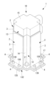
- FIG. 1 is a partial longitudinal cross-sectional view of a robot according to an embodiment of the present disclosure
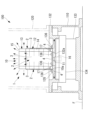
- FIG. FIG. 2 is an exploded perspective view illustrating a cooling structure for a servomotor according to an embodiment of the present disclosure provided in the robot of FIG. 1
- FIG. 3 is a perspective view showing a state in which the cooling structure for the servomotor of FIG. 2 is assembled
- FIG. 3 is a partial longitudinal sectional view illustrating heat flow in the cooling structure of the servomotor of FIG. 2;
- a cooling structure 1 for a servomotor 10 and a robot 100 according to an embodiment of the present disclosure will be described below with reference to the drawings.
- the robot 100 according to this embodiment is, for example, a vertical articulated robot installed on the floor F.
- the cooling structure 1 for the servomotor 10 cools the servomotor 10 of the drive mechanism 130 that rotates the swing drum 120 around the vertical axis with respect to the base 110 fixed to the floor F, for example.
- the driving mechanism 130 includes a base 110, a rotary table (robot structure) 132 supported above the base 110 so as to be rotatable about a vertical axis, and a combination of the base 110 and the rotary table 132. It has a speed reducer 133 arranged therebetween and a servomotor 10 fixed to the upper surface of the rotary table 132 .
- a rotating drum 120 is fixed to the rotary table 132 .
- the servomotor 10 includes a shaft 11 , a drive section 12 that rotates the shaft 11 , and an encoder 13 that detects the rotation of the shaft 11 .
- the drive unit 12 includes a rectangular cylindrical stator 14 and a rotor (not shown) supported inside the stator 14 so as to be rotatable around the central axis of the stator 14. It is fixed to the shaft 11.
- the shaft 11 protrudes from a mounting surface 10a provided on one end surface of the stator 14 in the central axis direction.
- the encoder 13 has a box-shaped casing 15 fixed to the end face opposite to the mounting face 10a with the stator 14 interposed therebetween.
- the encoder 13 includes a rotation detection mechanism (not shown) housed in the casing 15 and an electronic circuit (not shown). Any material may be used for the casing 15 .
- the servomotor 10 has a shaft 11 pass through a through hole 132a vertically penetrating a rotary table 132, and a gear 16 fixed to the tip of the shaft 11 is meshed with an input gear 134 of a reducer 133.
- the servomotor 10 is fixed to the rotary table 132 by bolts 17 with the mounting surface 10 a in close contact with a seat surface 135 machined on the upper surface of the rotary table 132 .
- a cooling structure 1 for a servomotor 10 includes, as shown in FIG. .
- Each heat transfer member 2 covers the side surface (outer surface) of the stator 14 , and has a motor contact portion 3 that is brought into close contact with the side surface, and the heat transfer member 2 is fixed to the bearing surface (surface) 135 on the upper surface of the rotary table 132 . and a fixing portion 4 of.
- the heat transfer member 2 is made of a material with high thermal conductivity, such as a metal such as an aluminum alloy. Any material may be used for the heat transfer member 2 .
- the fixed portion 4 is curved perpendicularly to the motor contact portion 3 and has a plurality of through holes 4a penetrating in the plate thickness direction.
- the heat transfer member 2 is fixed in close contact with the rotary table 132 by fastening bolts 136 passed through the through holes 4 a of the fixing portion 4 to screw holes 137 provided in the seat surface 135 of the rotary table 132 . be.
- the heat transfer member 2 is arranged such that the motor contact portion 3 is in close contact with each side surface of the stator 14 and the fixed portion 4 is in close contact with the bearing surface 135 of the rotary table 132 .
- a heat transfer path is formed for releasing heat to the rotary table 132 .
- the motor contact portion 3 of each heat transfer member 2 is brought into close contact only with each side surface of the stator 14 and is arranged at a position not in contact with the outer surface of the casing 15 of the encoder 13 .
- the heat transfer member 2 attached to the side where the connector is provided has a motor contact portion 3 shorter than the heat transfer member 2 attached to the other side in order to avoid contact with the connector.
- the motor contact portions 3 of the heat transfer member 2 are brought into close contact with the four side surfaces of the stator 14 , another part of the heat of the driving portion 12 is transferred to the motor contact portions 3 .
- the heat transferred to the flat plate-shaped motor contact portion 3 is conducted downward through the motor contact portion 3 and is transferred to the rotary table 132 via the fixed portion 4 in close contact with the seat surface 135 of the rotary table 132 . transmitted.
- the rotary table 132 has a large heat capacity, and the stator 14 and the heat transfer member 2 have a high thermal conductivity. As a result, the stator 14 is effectively cooled, and heat flowing from the stator 14 to the encoder 13 fixed to the stator 14 is sufficiently reduced.
- the encoder 13 Since the encoder 13 is in contact only with the stator 14, if the stator 14 is hotter than the encoder 13, the heat from the encoder 13 will be dissipated primarily by heat transfer to the surrounding air. be. That is, the encoder 13 is not in contact with the heat transfer member 2 for exhausting heat from the stator 14 , so the heat exhaust path from the encoder 13 is separated from the heat exhaust path from the stator 14 . Therefore, even if the temperature of the heat transfer member 2 rises due to exhaust heat from the stator 14, the exhaust heat from the encoder 13 is not hindered.
- the encoder 13 has a lower operating temperature upper limit than the stator 14, but the waste heat from the stator 14 is prevented from flowing into the encoder 13 via the heat transfer member 2, so the operating temperature is maintained at a proper operating temperature. .
- the heat of the stator 14 descends via the heat transfer member 2 and is discharged to the rotary table 132 positioned below the stator 14 . Therefore, the amount of heat radiated from the stator 14 to the surrounding air is reduced.
- the encoder 13 Since the encoder 13 is positioned above the stator 14, the heat of the stator 14 is discharged downward, thereby suppressing the temperature rise of the air around the encoder 13. Thereby, there is an advantage that the temperature difference between the encoder 13 and the surrounding air can be maintained, and heat can be effectively radiated from the encoder 13 to the surrounding air.
- the flat plate-shaped heat transfer member 2 is closely attached to the side surface of the servomotor 10, so that a large installation space is required around the servomotor 10. There is an advantage that there is no need to secure and space is saved.
- the cooling structure 1 can be externally mounted by a simple mounting method in which the plate-shaped heat transfer member 2 is brought into close contact with the side surface of the servomotor 10 from the outside and fixed to the bearing surface 135 of the rotary table 132 with bolts 136. can. As a result, the cooling structure 1 can be designed after the main mechanism is designed, which is advantageous for development design.
- An upright articulated robot is exemplified as the robot 100 including the cooling structure 1 for the servomotor 10 according to the present embodiment.
- the structure of the robot 100 illustrated in the description of this embodiment is an example, and is not limited to this.
- the rotary table 132 is exemplified as the robot structure, it may be applied when the servomotor 10 is attached to any other component having a large heat capacity.
- the L-shaped flat plate member is exemplified as the heat transfer member 2
- the shape of the heat transfer member 2 can be arbitrarily selected according to the seating surface 135 of the rotary table 132, which is the robot structure to which it is fixed. shape can be adopted.
- the heat transfer member 2 is brought into close contact with all four side surfaces of the stator 14 of the servomotor 10, it may be brought into close contact with one or more side surfaces.
- a filler such as heat conductive gel or a heat transfer sheet is added to the heat transfer member 2, the stator 14 and/or the heat transfer member 2. It may be interposed between the rotary table 132 and the rotary table 132 . As a result, the contact heat resistance in the heat transfer from the outer surface of the stator 14 to the heat transfer member 2 and the heat transfer from the heat transfer member 2 to the rotary table 132 is reduced, and the heat can be released more smoothly.
- the heat of the stator 14 is moved away from the encoder 13 by the heat transfer member 2 .
- the temperature of the heat transfer member 2 becomes high, the amount of heat released from the heat transfer member 2 to the surrounding air during heat conduction via the heat transfer member 2 increases.
- the outer surface of the heat transfer member 2 may be covered with a heat insulating material such as a heat insulating sheet or heat insulating paint that reduces the exhaust heat from the heat transfer member 2 to the surrounding air.
- a heat insulating material such as a heat insulating sheet or heat insulating paint that reduces the exhaust heat from the heat transfer member 2 to the surrounding air.
- the encoder 13 is exemplified above the drive unit 12, but the servomotor 10 may be installed in any other orientation.
- the cooling mechanism 1 of the present disclosure is particularly advantageous when the servomotor 10 is in the illustrated orientation for the following reasons. That is, without the cooling mechanism 1, the temperature of the air around the encoder 13 located above rises due to air expansion after the heat is released from the stator 14 to the surrounding air. However, by providing the cooling mechanism 1 of the present disclosure, heat radiation from the stator 14 to the surrounding air is suppressed, so the temperature difference between the encoder 13 and the surrounding air can be maintained.
- the heat emitted from the encoder 13 is mainly radiated to the surrounding air
- means for promoting heat radiation for example, providing fins on the casing 15 of the encoder 13, or using a fan to circulate the cooling air to the encoder 13. You may make it flow around.
- a heat transfer member for cooling the encoder 13 may be provided independently of the heat transfer member 2 for cooling the stator 14 .
- the space in which the encoder 13 is arranged may be separated from the space in which the stator 14 is arranged by a cover or the like.
- cooling structure heat transfer member (plate member) 10
- Servomotor Drive Unit 13
- Encoder 14
- Stator 100
- Rotary Table Robot Structure
Abstract
ロボット構造体(132)に固定されたサーボモータ(10)を冷却するサーボモータ(10)の冷却構造(1)であって、サーボモータ(10)が、ロータおよびステータ(14)を備える駆動部(12)と、ロータの回転を検出するエンコーダ(13)とを備え、ステータ(14)の外面とロボット構造体(132)の表面とに接触状態に固定され、ステータ(14)の熱をロボット構造体(132)に伝達する伝熱部材(2)を備え、伝熱部材(2)が、エンコーダ(13)の外面に接触していない、サーボモータ(10)の冷却構造(1)である。
Description
本開示は、サーボモータの冷却構造およびロボットに関するものである。
従来、動作中に発熱するサーボモータを冷却するために、サーボモータとサーボモータを内部空間に収容するモータハウジングとの間に冷却構造体を配置したロボットが知られている(例えば、特許文献1参照。)。
冷却構造体は、サーボモータからモータハウジングまで熱を伝達する熱伝導経路を形成する、例えば、アルミニウム等の金属から形成される熱伝導体である。
冷却構造体は、サーボモータからモータハウジングまで熱を伝達する熱伝導経路を形成する、例えば、アルミニウム等の金属から形成される熱伝導体である。
サーボモータには、性能および寿命を維持するための使用温度上限が定められている。使用温度上限は、サーボモータ全体において一律ではなく、ステータおよびロータにおいて高く、多くの場合エンコーダ等の電子回路において低い。
サーボモータのステータからエンコーダまでを同一の冷却構造体によってモータハウジングに接続する場合には、ステータからの排熱によって冷却構造体が加熱されることにより、エンコーダの熱の冷却構造体への排出が妨げられる場合がある。したがって、ロータおよびステータからの排熱によって妨げられることなく、使用温度上限の低いエンコーダの熱を効率よく排熱することが望まれている。
本開示の一態様は、ロボット構造体に固定されたサーボモータを冷却するサーボモータの冷却構造であって、前記サーボモータが、ロータおよびステータを備える駆動部と、前記ロータの回転を検出するエンコーダとを備え、前記ステータの外面と前記ロボット構造体の表面とに接触状態に固定され、前記ステータの熱を前記ロボット構造体に伝達する伝熱部材を備え、該伝熱部材が、前記エンコーダの外面に接触していない、サーボモータの冷却構造である。
本開示の一実施形態に係るサーボモータ10の冷却構造1およびロボット100について、図面を参照して以下に説明する。
本実施形態に係るロボット100は、例えば、床面Fに設置される垂直多関節型ロボットである。
本実施形態に係るロボット100は、例えば、床面Fに設置される垂直多関節型ロボットである。
本実施形態に係るサーボモータ10の冷却構造1は、例えば、床面Fに固定されたベース110に対して、鉛直軸線回りに旋回胴120を回転駆動する駆動機構130のサーボモータ10を冷却する構造である。
駆動機構130は、図1に示されるように、ベース110と、ベース110の上方に鉛直軸線回りに回転可能に支持された回転テーブル(ロボット構造体)132と、ベース110と回転テーブル132との間に配置された減速機133と、回転テーブル132の上面に固定されたサーボモータ10とを備えている。回転テーブル132には旋回胴120が固定されている。
駆動機構130は、図1に示されるように、ベース110と、ベース110の上方に鉛直軸線回りに回転可能に支持された回転テーブル(ロボット構造体)132と、ベース110と回転テーブル132との間に配置された減速機133と、回転テーブル132の上面に固定されたサーボモータ10とを備えている。回転テーブル132には旋回胴120が固定されている。
サーボモータ10は、シャフト11と、シャフト11を回転駆動する駆動部12と、シャフト11の回転を検出するエンコーダ13とを備えている。駆動部12は、図2に示されるように、四角筒状のステータ14と、ステータ14の内部にステータ14の中心軸回りに回転可能に支持されたロータ(図示略)とを備え、ロータがシャフト11に固定されている。シャフト11はステータ14の中心軸方向の一端面に設けられた取付面10aから突出している。
エンコーダ13は、ステータ14を挟んで取付面10aとは反対側の端面に固定された箱状のケーシング15を備えている。エンコーダ13はケーシング15内に収容された回転検出機構(図示略)および電子回路(図示略)を備えている。ケーシング15の材質は任意でよい。
サーボモータ10は、回転テーブル132に鉛直方向に貫通して設けられた貫通孔132aにシャフト11を貫通させ、シャフト11の先端に固定されたギヤ16を減速機133の入力ギヤ134に噛み合わせている。サーボモータ10は、取付面10aを回転テーブル132の上面に機械加工された座面135に密着させてボルト17によって、回転テーブル132に固定されている。
本実施形態に係るサーボモータ10の冷却構造1は、図2に示されるように、ステータ14の4つの側面にそれぞれ密着させられる4つの平板状の伝熱部材(平板部材)2を備えている。各伝熱部材2は、ステータ14の側面(外面)を覆い、該側面に密着させられるモータ接触部3と、伝熱部材2を回転テーブル132の上面の座面(表面)135に固定するための固定部4とを備えている。
伝熱部材2は、熱伝導率の大きな材質、例えば、アルミニウム合金等の金属により形成されている。伝熱部材2の材質は任意でよい。固定部4は、モータ接触部3に対して直角に湾曲させられているとともに、板厚方向に貫通する複数の貫通孔4aを備えている。伝熱部材2は、固定部4の貫通孔4aに貫通させたボルト136を回転テーブル132の座面135に設けられたネジ孔137に締結することにより、回転テーブル132に密着した状態に固定される。
伝熱部材2は、図3に示されるように、ステータ14の各側面にモータ接触部3を密着させ、かつ、回転テーブル132の座面135に固定部4を密着させることにより、ステータ14の発熱を回転テーブル132に逃がすための伝熱経路を形成する。
本実施形態においては、各伝熱部材2のモータ接触部3は、ステータ14の各側面のみに密着させられ、エンコーダ13のケーシング15の外面には接触しない位置に配置されている。コネクタが設けられた側面に取りけられる伝熱部材2は、コネクタとの接触を回避するために、他の側面に取り付けられる伝熱部材2よりも短い長さのモータ接触部3を有している。
本実施形態においては、各伝熱部材2のモータ接触部3は、ステータ14の各側面のみに密着させられ、エンコーダ13のケーシング15の外面には接触しない位置に配置されている。コネクタが設けられた側面に取りけられる伝熱部材2は、コネクタとの接触を回避するために、他の側面に取り付けられる伝熱部材2よりも短い長さのモータ接触部3を有している。
このように構成された本実施形態に係るサーボモータ10の冷却構造1の作用について以下に説明する。
本実施形態に係るサーボモータ10の冷却構造1によれば、図4に示されるように、サーボモータ10の作動によりロータおよびステータ14を備える駆動部12が発熱すると、駆動部12の熱は、その一部が、座面135に密着させられている取付面10aを経由して回転テーブル132へと伝達される。
本実施形態に係るサーボモータ10の冷却構造1によれば、図4に示されるように、サーボモータ10の作動によりロータおよびステータ14を備える駆動部12が発熱すると、駆動部12の熱は、その一部が、座面135に密着させられている取付面10aを経由して回転テーブル132へと伝達される。
さらに、ステータ14の4つの側面にはそれぞれ伝熱部材2のモータ接触部3が密着させられているので、駆動部12の熱の他の一部は、モータ接触部3へと伝達される。平板状のモータ接触部3に伝達された熱は、モータ接触部3を下方に向かって伝導され、回転テーブル132の座面135に密着している固定部4を経由して回転テーブル132へと伝達される。
回転テーブル132は、熱容量が大きく、また、ステータ14および伝熱部材2は熱伝導率が高いので、駆動部12において発生した熱は、そのほとんどが回転テーブル132にスムーズに伝達される。その結果、ステータ14が効果的に冷却され、ステータ14からステータ14に固定されているエンコーダ13へ流れる熱が十分に低減する。
エンコーダ13はステータ14のみに接触しているので、エンコーダ13よりもステータ14の方が高温となっている場合には、エンコーダ13からの熱は、主として、周囲の空気への熱伝達により放散される。すなわち、エンコーダ13は、ステータ14から排熱するための伝熱部材2には接触していないので、エンコーダ13からの排熱経路は、ステータ14からの排熱経路からは切り離されている。したがって、ステータ14からの排熱によって伝熱部材2の温度が上昇しても、エンコーダ13からの排熱が阻害されることがない。
そして、ステータ14が伝熱部材2によって効果的に冷却されることにより、ステータ14からエンコーダ13への入熱量が低減し、周囲の空気への放熱のみによってもエンコーダ13を十分に冷却することができる。エンコーダ13は、ステータ14よりも使用温度上限が低いが、ステータ14からの排熱が伝熱部材2を経由してエンコーダ13に流入することが防止されるので、適正な使用温度に維持される。
また、ステータ14が効率的に冷却される結果、ステータ14よりもエンコーダ13の方が高温となっている場合には、エンコーダ13において発生した熱の一部は、冷却されたステータ14を経由して回転テーブル132に排出される。これによっても、エンコーダ13を効率的に冷却することができる。
また、上述したように、本実施形態によれば、ステータ14の熱は伝熱部材2を経由して下降し、ステータ14の下方に位置する回転テーブル132に排出される。したがって、ステータ14から周囲の空気への放熱量が低減する。
エンコーダ13はステータ14の上方に位置しているので、ステータ14の熱が下方に排出されることにより、エンコーダ13の周囲の空気の温度上昇が抑えられる。これにより、エンコーダ13と周囲の空気との温度差が維持され、エンコーダ13から周囲の空気への効果的な放熱を図ることができるという利点がある。
また、本実施形態に係るサーボモータ10の冷却構造1によれば、平板状の伝熱部材2をサーボモータ10の側面に密着するように沿わせるので、サーボモータ10の周囲に大きな設置スペースを確保せずに済み、省スペースであるという利点がある。また、平板状の伝熱部材2を、サーボモータ10の外側から側面に密着させて回転テーブル132の座面135にボルト136によって固定する簡易な取付方法によって、冷却構造1を外付けすることができる。これにより、冷却構造1の設計を主要機構部の設計後に行うことができ、開発設計に有利である。
なお、本実施形態に係るサーボモータ10の冷却構造1を備えるロボット100として、直立多関節型ロボットを例示した。この実施形態の説明において図示したロボット100の構造は一例であり、これに限定されるものではない。ロボット構造体として回転テーブル132を例示したが、他の任意の熱容量の大きな部品にサーボモータ10が取り付けられる場合に適用してもよい。
また、伝熱部材2としてL字状に湾曲させた平板部材を例示したが、伝熱部材2の形状は、固定先のロボット構造体である回転テーブル132の座面135等に合わせて任意の形状を採用することができる。
また、伝熱部材2をサーボモータ10のステータ14の4つの側面全てに密着させることとしたが、1以上の側面に密着させることにしてもよい。
また、伝熱部材2をサーボモータ10のステータ14の4つの側面全てに密着させることとしたが、1以上の側面に密着させることにしてもよい。
また、ステータ14の外面および回転テーブル132の座面135と伝熱部材2との密着度を高めるために、熱伝導ジェルあるいは伝熱シート等の充填材を伝熱部材2とステータ14および/または回転テーブル132との間に介在させてもよい。これにより、ステータ14の外面から伝熱部材2への熱伝達および伝熱部材2から回転テーブル132への熱伝達における接触熱抵抗が低減され、よりスムーズに放熱を図ることができる。
さらに、本実施形態においては、ステータ14の熱を伝熱部材2によってエンコーダ13から離れる方向に移動させる。伝熱部材2が高温になると伝熱部材2を経由して熱伝導する途中における伝熱部材2から周囲の空気への放熱が増大する。
そこで、伝熱部材2の外面を、伝熱部材2から周囲の空気への排熱を低減する断熱シートあるいは断熱塗料等の断熱材によって覆うことにしてもよい。これにより、伝熱部材2から大気への放熱を低減して、エンコーダ13の周囲の空気の温度上昇を低減することができる。
サーボモータ10について、駆動部12の上部にエンコーダ13があるよう例示したが、他の任意の姿勢にサーボモータ10を設置してもよい。一方、本開示の冷却機構1は、サーボモータ10が例示の姿勢のとき、下記理由により特に有利である。すなわち、冷却機構1が無い場合、ステータ14から周囲の空気への放熱後に空気膨張によって上部にあるエンコーダ13の周囲の空気の温度上昇が生じてしまう。しかし、本開示の冷却機構1を備えることにより、ステータ14から周囲の空気への放熱が抑制されるため、エンコーダ13と周囲の空気との温度差を維持することができる。
また、エンコーダ13からの排熱が、主として周囲の空気への放熱により行われるので、放熱を促進するための手段、例えば、エンコーダ13のケーシング15にフィンを設けたり、ファンによって冷却空気をエンコーダ13の周囲に流動させたりしてもよい。また、ステータ14を冷却するための伝熱部材2とは独立して、エンコーダ13を冷却するための伝熱部材を設けてもよい。また、カバーなどによって、ステータ14が配置されている空間からエンコーダ13が配置されている空間を切り離すことにしてもよい。
1 冷却構造
2 伝熱部材(平板部材)
10 サーボモータ
12 駆動部
13 エンコーダ
14 ステータ
100 ロボット
132 回転テーブル(ロボット構造体)
135 座面(表面)
2 伝熱部材(平板部材)
10 サーボモータ
12 駆動部
13 エンコーダ
14 ステータ
100 ロボット
132 回転テーブル(ロボット構造体)
135 座面(表面)
Claims (8)
- ロボット構造体に固定されたサーボモータを冷却するサーボモータの冷却構造であって、
前記サーボモータが、ロータおよびステータを備える駆動部と、前記ロータの回転を検出するエンコーダとを備え、
前記ステータの外面と前記ロボット構造体の表面とに接触状態に固定され、前記ステータの熱を前記ロボット構造体に伝達する伝熱部材を備え、
該伝熱部材が、前記エンコーダの外面に接触していない、サーボモータの冷却構造。 - 前記伝熱部材が、前記ステータの外面を覆い、前記エンコーダの外面を覆わない位置に配置されている請求項1に記載のサーボモータの冷却構造。
- 前記サーボモータが、前記ステータの上方に前記エンコーダを配置する姿勢によって前記ロボット構造体に固定されている請求項1または請求項2に記載のサーボモータの冷却構造。
- 前記伝熱部材から周囲の空気への放熱を制限する断熱材を備える請求項3に記載のサーボモータの冷却構造。
- 前記伝熱部材が、前記ステータの外面および前記ロボット構造体の表面に密着させられる平板部材を備える請求項1から請求項4のいずれかに記載のサーボモータの冷却構造。
- 前記伝熱部材が、前記平板部材と前記ステータの外面との間もしくは前記平板部材と前記ロボット構造体の表面との間の密着を促進する充填材を備える請求項5に記載のサーボモータの冷却構造。
- 前記伝熱部材が、前記ステータの2以上の外面にそれぞれ密着させられている請求項1から請求項6のいずれかに記載のサーボモータの冷却構造。
- 請求項1から請求項7のいずれかに記載のサーボモータの冷却構造を備えるロボット。
Priority Applications (2)
| Application Number | Priority Date | Filing Date | Title |
|---|---|---|---|
| PCT/JP2022/002797 WO2023144908A1 (ja) | 2022-01-26 | 2022-01-26 | サーボモータの冷却構造およびロボット |
| TW112101110A TW202344360A (zh) | 2022-01-26 | 2023-01-10 | 伺服馬達的冷卻結構及機器人 |
Applications Claiming Priority (1)
| Application Number | Priority Date | Filing Date | Title |
|---|---|---|---|
| PCT/JP2022/002797 WO2023144908A1 (ja) | 2022-01-26 | 2022-01-26 | サーボモータの冷却構造およびロボット |
Publications (1)
| Publication Number | Publication Date |
|---|---|
| WO2023144908A1 true WO2023144908A1 (ja) | 2023-08-03 |
Family
ID=87471239
Family Applications (1)
| Application Number | Title | Priority Date | Filing Date |
|---|---|---|---|
| PCT/JP2022/002797 WO2023144908A1 (ja) | 2022-01-26 | 2022-01-26 | サーボモータの冷却構造およびロボット |
Country Status (2)
| Country | Link |
|---|---|
| TW (1) | TW202344360A (ja) |
| WO (1) | WO2023144908A1 (ja) |
Citations (5)
| Publication number | Priority date | Publication date | Assignee | Title |
|---|---|---|---|---|
| JPS61249286A (ja) * | 1985-04-27 | 1986-11-06 | フアナツク株式会社 | 産業用ロボツト |
| JP2014046398A (ja) * | 2012-08-31 | 2014-03-17 | Fanuc Ltd | モータを冷却する冷却構造体を有する多関節ロボット |
| JP2018191449A (ja) * | 2017-05-09 | 2018-11-29 | 三菱電機株式会社 | サーボモータ及びその製造方法 |
| WO2019003569A1 (ja) * | 2017-06-26 | 2019-01-03 | 三菱電機株式会社 | 駆動ユニットおよびロボット |
| JP2020015146A (ja) * | 2018-07-26 | 2020-01-30 | キヤノン株式会社 | ロボットアーム、ロボット装置 |
-
2022
- 2022-01-26 WO PCT/JP2022/002797 patent/WO2023144908A1/ja unknown
-
2023
- 2023-01-10 TW TW112101110A patent/TW202344360A/zh unknown
Patent Citations (5)
| Publication number | Priority date | Publication date | Assignee | Title |
|---|---|---|---|---|
| JPS61249286A (ja) * | 1985-04-27 | 1986-11-06 | フアナツク株式会社 | 産業用ロボツト |
| JP2014046398A (ja) * | 2012-08-31 | 2014-03-17 | Fanuc Ltd | モータを冷却する冷却構造体を有する多関節ロボット |
| JP2018191449A (ja) * | 2017-05-09 | 2018-11-29 | 三菱電機株式会社 | サーボモータ及びその製造方法 |
| WO2019003569A1 (ja) * | 2017-06-26 | 2019-01-03 | 三菱電機株式会社 | 駆動ユニットおよびロボット |
| JP2020015146A (ja) * | 2018-07-26 | 2020-01-30 | キヤノン株式会社 | ロボットアーム、ロボット装置 |
Also Published As
| Publication number | Publication date |
|---|---|
| TW202344360A (zh) | 2023-11-16 |
Similar Documents
| Publication | Publication Date | Title |
|---|---|---|
| EP1627459B1 (en) | Brushless motor | |
| CN108207097B (zh) | 一种隔热装置和电子产品 | |
| US8985265B2 (en) | Electric power steering apparatus | |
| JPH08274480A (ja) | ヒートシンク装置およびそれに用いられる送風装置ならびにそれを用いた電子機器 | |
| JP2015198168A (ja) | 電子装置、電力変換装置及び回転電機 | |
| JP6505311B2 (ja) | 電動機および換気扇 | |
| JP2019078233A (ja) | 真空ポンプ | |
| WO2017026128A1 (ja) | モータ装置 | |
| WO2023144908A1 (ja) | サーボモータの冷却構造およびロボット | |
| KR20190081330A (ko) | 모터의 인버터 방열커버 | |
| JP6068933B2 (ja) | 車両用モータユニット | |
| CN108506225B (zh) | 电源一体型真空泵 | |
| WO2019130442A1 (ja) | モータ駆動装置 | |
| WO2019003569A1 (ja) | 駆動ユニットおよびロボット | |
| JP6001966B2 (ja) | 車両用モータユニット | |
| JP2019217597A (ja) | コントローラおよびこのコントローラを備えた動力工具 | |
| JP6092972B1 (ja) | 複数のスイッチング素子を備える工作機械のモータ駆動装置 | |
| CN209936967U (zh) | 机器人 | |
| WO2020110238A1 (ja) | 電動機 | |
| JP6026063B1 (ja) | モータ装置 | |
| JPH08163826A (ja) | 回転検出器を備えた回転電機 | |
| JP2018191449A (ja) | サーボモータ及びその製造方法 | |
| JP3590127B2 (ja) | 電子部品冷却装置 | |
| US20230253854A1 (en) | Electric motor with printed circuit board | |
| JPH04112794U (ja) | 産業用ロボツトのアーム |
Legal Events
| Date | Code | Title | Description |
|---|---|---|---|
| 121 | Ep: the epo has been informed by wipo that ep was designated in this application |
Ref document number: 22923776 Country of ref document: EP Kind code of ref document: A1 |