WO2023139810A1 - 電動車両の制御方法、及び、電動車両の制御装置 - Google Patents
電動車両の制御方法、及び、電動車両の制御装置 Download PDFInfo
- Publication number
- WO2023139810A1 WO2023139810A1 PCT/JP2022/018304 JP2022018304W WO2023139810A1 WO 2023139810 A1 WO2023139810 A1 WO 2023139810A1 JP 2022018304 W JP2022018304 W JP 2022018304W WO 2023139810 A1 WO2023139810 A1 WO 2023139810A1
- Authority
- WO
- WIPO (PCT)
- Prior art keywords
- electric vehicle
- vehicle
- torque
- target value
- control method
- Prior art date
- Legal status (The legal status is an assumption and is not a legal conclusion. Google has not performed a legal analysis and makes no representation as to the accuracy of the status listed.)
- Ceased
Links
Images









Classifications
-
- B—PERFORMING OPERATIONS; TRANSPORTING
- B60—VEHICLES IN GENERAL
- B60L—PROPULSION OF ELECTRICALLY-PROPELLED VEHICLES; SUPPLYING ELECTRIC POWER FOR AUXILIARY EQUIPMENT OF ELECTRICALLY-PROPELLED VEHICLES; ELECTRODYNAMIC BRAKE SYSTEMS FOR VEHICLES IN GENERAL; MAGNETIC SUSPENSION OR LEVITATION FOR VEHICLES; MONITORING OPERATING VARIABLES OF ELECTRICALLY-PROPELLED VEHICLES; ELECTRIC SAFETY DEVICES FOR ELECTRICALLY-PROPELLED VEHICLES
- B60L15/00—Methods, circuits, or devices for controlling the traction-motor speed of electrically-propelled vehicles
- B60L15/20—Methods, circuits, or devices for controlling the traction-motor speed of electrically-propelled vehicles for control of the vehicle or its driving motor to achieve a desired performance, e.g. speed, torque, programmed variation of speed
-
- B—PERFORMING OPERATIONS; TRANSPORTING
- B60—VEHICLES IN GENERAL
- B60L—PROPULSION OF ELECTRICALLY-PROPELLED VEHICLES; SUPPLYING ELECTRIC POWER FOR AUXILIARY EQUIPMENT OF ELECTRICALLY-PROPELLED VEHICLES; ELECTRODYNAMIC BRAKE SYSTEMS FOR VEHICLES IN GENERAL; MAGNETIC SUSPENSION OR LEVITATION FOR VEHICLES; MONITORING OPERATING VARIABLES OF ELECTRICALLY-PROPELLED VEHICLES; ELECTRIC SAFETY DEVICES FOR ELECTRICALLY-PROPELLED VEHICLES
- B60L2200/00—Type of vehicles
- B60L2200/28—Trailers
-
- B—PERFORMING OPERATIONS; TRANSPORTING
- B60—VEHICLES IN GENERAL
- B60L—PROPULSION OF ELECTRICALLY-PROPELLED VEHICLES; SUPPLYING ELECTRIC POWER FOR AUXILIARY EQUIPMENT OF ELECTRICALLY-PROPELLED VEHICLES; ELECTRODYNAMIC BRAKE SYSTEMS FOR VEHICLES IN GENERAL; MAGNETIC SUSPENSION OR LEVITATION FOR VEHICLES; MONITORING OPERATING VARIABLES OF ELECTRICALLY-PROPELLED VEHICLES; ELECTRIC SAFETY DEVICES FOR ELECTRICALLY-PROPELLED VEHICLES
- B60L2240/00—Control parameters of input or output; Target parameters
- B60L2240/10—Vehicle control parameters
- B60L2240/12—Speed
-
- B—PERFORMING OPERATIONS; TRANSPORTING
- B60—VEHICLES IN GENERAL
- B60L—PROPULSION OF ELECTRICALLY-PROPELLED VEHICLES; SUPPLYING ELECTRIC POWER FOR AUXILIARY EQUIPMENT OF ELECTRICALLY-PROPELLED VEHICLES; ELECTRODYNAMIC BRAKE SYSTEMS FOR VEHICLES IN GENERAL; MAGNETIC SUSPENSION OR LEVITATION FOR VEHICLES; MONITORING OPERATING VARIABLES OF ELECTRICALLY-PROPELLED VEHICLES; ELECTRIC SAFETY DEVICES FOR ELECTRICALLY-PROPELLED VEHICLES
- B60L2240/00—Control parameters of input or output; Target parameters
- B60L2240/10—Vehicle control parameters
- B60L2240/14—Acceleration
- B60L2240/16—Acceleration longitudinal
-
- B—PERFORMING OPERATIONS; TRANSPORTING
- B60—VEHICLES IN GENERAL
- B60L—PROPULSION OF ELECTRICALLY-PROPELLED VEHICLES; SUPPLYING ELECTRIC POWER FOR AUXILIARY EQUIPMENT OF ELECTRICALLY-PROPELLED VEHICLES; ELECTRODYNAMIC BRAKE SYSTEMS FOR VEHICLES IN GENERAL; MAGNETIC SUSPENSION OR LEVITATION FOR VEHICLES; MONITORING OPERATING VARIABLES OF ELECTRICALLY-PROPELLED VEHICLES; ELECTRIC SAFETY DEVICES FOR ELECTRICALLY-PROPELLED VEHICLES
- B60L2240/00—Control parameters of input or output; Target parameters
- B60L2240/10—Vehicle control parameters
- B60L2240/26—Vehicle weight
-
- B—PERFORMING OPERATIONS; TRANSPORTING
- B60—VEHICLES IN GENERAL
- B60L—PROPULSION OF ELECTRICALLY-PROPELLED VEHICLES; SUPPLYING ELECTRIC POWER FOR AUXILIARY EQUIPMENT OF ELECTRICALLY-PROPELLED VEHICLES; ELECTRODYNAMIC BRAKE SYSTEMS FOR VEHICLES IN GENERAL; MAGNETIC SUSPENSION OR LEVITATION FOR VEHICLES; MONITORING OPERATING VARIABLES OF ELECTRICALLY-PROPELLED VEHICLES; ELECTRIC SAFETY DEVICES FOR ELECTRICALLY-PROPELLED VEHICLES
- B60L2240/00—Control parameters of input or output; Target parameters
- B60L2240/40—Drive Train control parameters
- B60L2240/42—Drive Train control parameters related to electric machines
- B60L2240/423—Torque
-
- B—PERFORMING OPERATIONS; TRANSPORTING
- B60—VEHICLES IN GENERAL
- B60L—PROPULSION OF ELECTRICALLY-PROPELLED VEHICLES; SUPPLYING ELECTRIC POWER FOR AUXILIARY EQUIPMENT OF ELECTRICALLY-PROPELLED VEHICLES; ELECTRODYNAMIC BRAKE SYSTEMS FOR VEHICLES IN GENERAL; MAGNETIC SUSPENSION OR LEVITATION FOR VEHICLES; MONITORING OPERATING VARIABLES OF ELECTRICALLY-PROPELLED VEHICLES; ELECTRIC SAFETY DEVICES FOR ELECTRICALLY-PROPELLED VEHICLES
- B60L2270/00—Problem solutions or means not otherwise provided for
- B60L2270/10—Emission reduction
- B60L2270/14—Emission reduction of noise
- B60L2270/145—Structure borne vibrations
-
- Y—GENERAL TAGGING OF NEW TECHNOLOGICAL DEVELOPMENTS; GENERAL TAGGING OF CROSS-SECTIONAL TECHNOLOGIES SPANNING OVER SEVERAL SECTIONS OF THE IPC; TECHNICAL SUBJECTS COVERED BY FORMER USPC CROSS-REFERENCE ART COLLECTIONS [XRACs] AND DIGESTS
- Y02—TECHNOLOGIES OR APPLICATIONS FOR MITIGATION OR ADAPTATION AGAINST CLIMATE CHANGE
- Y02T—CLIMATE CHANGE MITIGATION TECHNOLOGIES RELATED TO TRANSPORTATION
- Y02T10/00—Road transport of goods or passengers
- Y02T10/60—Other road transportation technologies with climate change mitigation effect
- Y02T10/72—Electric energy management in electromobility
Definitions
- the present invention relates to an electric vehicle control method and an electric vehicle control device.
- JP2003-009566A discloses a control method for suppressing vibrations occurring in an electric vehicle based on torque transmission characteristics of a power transmission mechanism connected between the output shaft of a motor and driving wheels.
- electric vehicles may tow other vehicles.
- the total weight of the towing electric vehicle and the towed other vehicle is the substantial vehicle weight of the electric vehicle. Therefore, when the electric vehicle is towed, the change in vehicle weight to be considered becomes a large change that cannot be ignored.
- the conventional damping control cannot provide sufficient damping effect.
- the torque transmission characteristics of the power transmission mechanism are usually determined by the structure of the power transmission mechanism, etc., and do not reflect the presence or absence of traction. Therefore, the conventional damping control cannot sufficiently suppress the vibration caused by the towing of other vehicles or the like. That is, when the electric vehicle is towed, the conventional damping control cannot provide a sufficient damping effect, and the electric vehicle vibrates. As a result, when the vehicle is towed, the electric vehicle may not be able to achieve a torque rise or smooth acceleration required by the vehicle operation.
- An object of the present invention is to provide an electric vehicle control method and an electric vehicle control apparatus that can achieve a rise in torque required by vehicle operation and smooth acceleration even when the electric vehicle is towed.
- An aspect of the present invention is a control method for an electric vehicle that has a motor that is a drive source and a connecting portion that connects another vehicle, and runs by towing a connected vehicle that is another vehicle that is connected to the connecting portion.
- a basic torque target value representing the torque to be output by the motor is calculated based on the vehicle operation. Further, based on the dynamic characteristics of the coupling portion to which the coupled vehicle is coupled, correction processing is performed on the basic torque target value to suppress the longitudinal vibration component that occurs in the electric vehicle due to the coupled vehicle being coupled to the coupling portion, thereby calculating the final torque command, which is the final command value for the torque. Then, the motor is controlled based on this final torque command value.
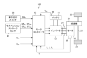
- FIG. 1 is an explanatory diagram showing a schematic configuration of an electric vehicle.
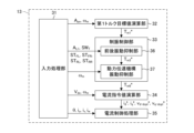
- FIG. 2 is a block diagram showing the configuration of the motor controller.
- FIG. 3 is a graph showing an example of an accelerator opening-torque table.
- FIG. 4 is an explanatory diagram showing a dynamic model of an electric vehicle in which a connected vehicle is connected to a connecting portion.
- FIG. 5 is a block diagram showing the configuration of the longitudinal vibration suppressing section.
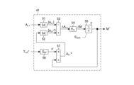
- FIG. 6 is a block diagram showing the configuration of the gross weight calculator.
- FIG. 7 is a block diagram showing the configuration of the electric vehicle weight calculator.
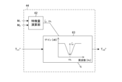
- FIG. 8 is a block diagram showing the configuration of the natural vibration suppressing section.
- FIG. 9 is a block diagram showing the configuration of the power transmission mechanism vibration suppression unit.
- FIG. 1 is an explanatory diagram showing a schematic configuration of an electric vehicle.
- FIG. 2 is a block diagram showing the configuration of the motor controller.
- FIG. 3 is a graph showing an example of an accelerator opening-tor
- FIG. 10 is a graph showing transfer characteristics H 2 (s) used in the disturbance estimator.
- FIG. 11 is a block diagram showing the configuration of a current command value calculator and a current control processor.
- FIG. 12 is a time chart showing the longitudinal acceleration and the like during towing.
- FIG. 13 is a time chart showing longitudinal acceleration and the like when the weight of the connected vehicle is large.
- FIG. 14 is a block diagram showing a partial configuration of a damping control section in the second embodiment.
- FIG. 15 is a block diagram showing the configuration of the longitudinal vibration suppressing section in the third embodiment.
- FIG. 16 is a block diagram showing the configuration of the natural vibration suppression section in the third embodiment.
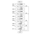
- FIG. 17 is a flowchart for updating the natural vibration frequency and the like.
- FIG. 18 is a time chart showing longitudinal acceleration and the like in a driving scene in which the natural vibration frequency and the like are updated.
- FIG. 19 is a time chart showing the longitudinal acceleration and the like after updating the natural vibration frequency and the like.
- FIG. 20 is a block diagram showing a partial configuration of the damping control unit when compensation for longitudinal vibrations peculiar to towing and compensation for power transmission mechanism vibrations are substantially integrally performed.
- FIG. 1 is an explanatory diagram showing a schematic configuration of an electric vehicle 100.
- the electric vehicle 100 can be connected to another vehicle or the like and can be towed to travel.
- the other vehicle or the like is, for example, a vehicle capable of self-propelled or a vehicle (trailer) that does not have self-propelled capability.
- the electric vehicle 100 functions as a towing vehicle that tows other vehicles or the like, but the electric vehicle 100 can travel without towing other vehicles or the like.
- the electric vehicle 100 includes a motor 10, a battery 11, an inverter 12, and a motor controller 13.
- Motor 10 is a drive source of electric vehicle 100 .
- Torque generated by the motor 10 (hereinafter referred to as motor torque Tm (not shown)) is transmitted to drive wheels 23 via a speed reducer 21 and a drive shaft 22 .
- the motor 10 can generate a regenerative braking force on the driving wheels 23 by so-called regenerative control when rotating together with the driving wheels 23 .
- the motor 10 recovers the kinetic energy of the electric vehicle 100 as electrical energy.
- the motor 10 is, for example, a three-phase AC synchronous motor. Currents i u , iv , and i w flowing through each phase of motor 10 can be detected using current sensors 24 .
- the rotor phase ⁇ of the motor 10 is detected using a rotation sensor 25 such as a resolver or encoder.
- the speed reducer 21 and the drive shaft 22 constitute a power transmission mechanism (torque transmission system) that transmits power (torque) from the motor 10 to the drive wheels 23 .
- Battery 11 supplies power to drive motor 10 via inverter 12 . Also, the battery 11 can be charged with regenerated electric power generated in the motor 10 by regenerative control. Battery 11 is a DC power supply.
- the DC voltage Vdc output by the battery 11 is detected by, for example, the voltage sensor 26 and obtained directly from the voltage sensor 26 or via a battery controller (not shown).
- the inverter 12 converts the DC power supplied from the battery 11 into AC power and supplies the AC power to the motor 10 .
- the inverter 12 converts AC regenerated power input from the motor 10 by regeneration control into DC power and inputs the DC power to the battery 11 .
- the inverter 12 is composed of a plurality of switching elements (not shown), and converts the DC power from the battery 11 into AC power by turning on/off these switching elements.
- inverter 12 converts AC regenerated power input from motor 10 into DC power by turning on/off switching elements. Two pairs of switching elements are provided for each phase of the motor 10 .
- the switching element is, for example, a power semiconductor element such as an IGBT (insulated gate bipolar transistor) or a MOS-FET (metal oxide semiconductor field effect transistor).
- the motor controller 13 generates a PWM signal (pulse width modulation signal) that is a drive signal for the inverter 12 based on various vehicle variables that are parameters representing the control state of the electric vehicle 100 or each part that configures the electric vehicle 100 .
- the motor controller 13 controls the motor 10 by driving the inverter 12 with the generated PWM signal.
- the motor controller 13 acquires or calculates the rotor phase ⁇ , currents i u , iv , i w , DC voltage V dc , longitudinal acceleration A L1 , accelerator opening A po , suspension stroke amounts ST FL , ST FR , ST RL , ST RR , traction signal SW T , etc. as vehicle variables.
- the longitudinal acceleration AL1 is acceleration in the longitudinal direction (longitudinal direction) of the electric vehicle 100, and is detected by, for example, an acceleration sensor (not shown). Also, the longitudinal acceleration AL1 may be obtained from a controller (not shown). Further, the accelerator opening Apo is a parameter representing the operation amount of the accelerator provided in the electric vehicle 100, and is detected by a sensor or the like (not shown). Accelerator opening degree A po represents a required amount of driving force (torque) for electric vehicle 100 according to vehicle operation.
- Suspension stroke amounts ST FL , ST FR , ST RL , and ST RR are stroke amounts of suspensions provided for the left front wheel, right front wheel, left rear wheel, and right rear wheel of electric vehicle 100, respectively.
- Suspension stroke amounts ST FL , ST FR , ST RL , and ST RR are detected by suspension stroke sensors 27 provided for each suspension.
- the front wheels of the electric vehicle 100 are driving wheels 23, and the rear wheels are driven wheels.
- the traction travel signal SWT is a signal output by the traction travel switch 28 .
- the towing switch 28 is a control mode changeover switch operated by the driver or the like when the electric vehicle 100 connects another vehicle to the connecting portion 101 (see FIG. 4) and tows the other vehicle.
- the connecting portion 101 is a member that connects another vehicle or the like, and is a towing member such as a so-called trailer hitch.
- another vehicle or the like a towed vehicle or the like that is connected to the connecting portion 101 and towed by the electric vehicle 100 is referred to as a "connected vehicle 102".
- the towing signal SWT is a criterion indicating whether or not the electric vehicle 100 is towing. Specifically, when the electric vehicle 100 tows the connected vehicle 102 and travels, the traction travel signal SWT is set to ON by operating the traction travel switch 28 . Based on the towing signal SWT , the motor controller 13 determines whether or not the connected vehicle 102 is connected to the connecting portion 101, that is, whether or not the vehicle is towed. Then, according to the determination result, motor controller 13 changes the content of damping control for suppressing vibrations occurring in electric vehicle 100 .
- FIG. 2 is a block diagram showing the configuration of the motor controller 13.
- the motor controller 13 is configured by one or a plurality of computers and is programmed to repeatedly execute the processing of each unit described below at a predetermined cycle.
- the motor controller 13 includes an input processing unit 31, a first torque target value calculation unit 32 (basic torque target value calculation unit), a damping control unit 33 (correction processing unit), a current command value calculation unit 34, and a current control processing unit 35.
- the input processing unit 31 acquires vehicle variables used for various controls and/or calculations executed by the motor controller 13, or executes input processing for calculation. For example, the input processing unit 31 acquires, as vehicle variables, the rotor phase ⁇ , currents i u and iv , DC voltage V dc , longitudinal acceleration A L1 , accelerator opening A po , suspension stroke amounts ST FL , ST FR , ST RL , and ST RR , and traction signal SW T.
- the input processing unit 31 calculates the rotor angular velocity ⁇ [rad/s] (electrical angular velocity) of the motor 10 by differentiating the rotor phase ⁇ (electrical angle).
- the input processing unit 31 divides the rotor angular velocity ⁇ by the pole logarithm of the motor 10 to calculate the rotation speed of the motor 10 (hereinafter referred to as motor rotation speed) ⁇ m [rad/s] (mechanical angular velocity).
- the input processing unit 31 may calculate the motor rotation speed N m [rpm] by multiplying the motor rotation speed ⁇ m by a unit conversion factor (60/2 ⁇ ).
- the current sensor 24 detects the U-phase current iu and the V-phase current iv . Therefore, the input processing unit 31 calculates the W-phase current iw using the U-phase current iu and the V-phase current iv based on the following equation (1).
- a first torque target value calculation unit 32 calculates a first torque target value T m1 * based on the accelerator opening A po and the motor rotation speed ⁇ m .
- the first torque target value T m1 * is a torque target value calculated based on vehicle operation and represents the torque (motor torque T m ) that the motor 10 should output. That is, the first torque target value T m1 * is a basic torque target value (basic torque target value) for generating the driving force required for electric vehicle 100 .
- FIG. 3 is a graph showing an example of an accelerator opening-torque table. As shown in FIG. 3, it is a table in which the accelerator opening A po and the motor rotation speed ⁇ m are associated in advance with the first torque target value T m1 * by experiments, simulations, or the like.
- the first torque target value calculation unit 32 calculates the first torque target value T m1 * by referring to this accelerator opening-torque table based on the accelerator opening A po and the motor rotation speed ⁇ m .
- Vibration suppression control unit 33 executes vibration suppression control processing for calculating a sixth target torque value T m6 * by correcting first target torque value T m1 * so as to suppress vibration occurring in electric vehicle 100.
- the sixth torque target value T m6 * is used as the final torque command value, which is the final command value for the torque to be output by the motor 10 .
- vibrations there are two types of vibrations that occur in the electric vehicle 100 .
- One is a vibration inherent to the connection of the vehicle 102 to the connection portion 101 when the electrically powered vehicle 100 tows the vehicle 102 and travels. This vibration occurs in the longitudinal direction of electric vehicle 100 .
- the vibration caused by the change in acceleration in the front-rear direction caused by the connection of the vehicle 102 to the connection portion 101 is referred to as the front-rear vibration.
- Another vibration is the vibration caused by transmitting the motor torque Tm to the drive wheels 23 through the power transmission mechanism.
- This vibration includes, for example, vibration caused by disturbance such as a road surface gradient, and vibration caused by gear backlash, torsion of the drive shaft 22, and the like.
- the vibration generated in the power transmission mechanism will be referred to as power transmission mechanism vibration.
- the damping control unit 33 includes a longitudinal vibration suppressing unit 36 and a power transmission mechanism vibration suppressing unit 37 in order to suppress these vibrations.
- the longitudinal vibration suppression unit 36 executes longitudinal vibration suppression processing.
- the longitudinal vibration suppression process is a process for suppressing longitudinal vibrations that occur when the vehicle 102 is towed based on the dynamic characteristics of the connecting portion 101 to which the vehicle 102 is coupled.
- the dynamic characteristics of the connecting portion 101 to which the articulated vehicle 102 is connected refer to temporal changes in movement of the connecting portion (including the connecting portion 101) caused by the articulated vehicle 102 being connected to the connecting portion 101.
- the natural vibration frequency ⁇ t and the damping coefficient ⁇ t are indices or parameters for specifying temporal changes in the connecting parts. Therefore, in the present embodiment, the temporal change of the connecting portion is specified by the natural vibration frequency ⁇ t and the damping coefficient ⁇ t , or both the natural vibration frequency ⁇ t and the damping coefficient ⁇ t .
- longitudinal vibration suppressing section 36 determines whether or not connected vehicle 102 is connected to connecting section 101 based on towing travel signal SWT .
- the longitudinal vibration suppressing portion 36 calculates the second torque target value T m2 * (see FIG. 5) by executing the first vibration damping correction process for reducing or removing the longitudinal vibration component on the first torque target value T m1 * . Then, the longitudinal vibration suppressing section 36 outputs the second torque target value T m2 * as the third torque target value T m3 * , which is the output of the longitudinal vibration suppressing section 36 .
- the longitudinal vibration suppressing section 36 performs this first damping correction process based on the longitudinal acceleration A L1 and the suspension stroke amounts ST FL , ST FR , ST RL and ST RR .
- longitudinal vibration suppressing portion 36 outputs first torque target value T m1 * as it is as third torque target value T m3 * .
- the power transmission mechanism vibration suppressing unit 37 calculates a sixth target torque value T m6 * without sacrificing the response of the drive wheels 23 by performing a second vibration suppression correction process (power transmission mechanism vibration suppression process) for further suppressing vibration of the power transmission mechanism on the third target torque value T m3 * .
- the power transmission mechanism vibration suppression unit 37 performs this second vibration suppression correction process based on the motor rotation speed ⁇ m .
- the current command value calculation unit 34 calculates a d-axis current target value id* and a q -axis current target value iq * (hereinafter referred to as dq-axis current target values id * and iq * ) based on the sixth torque target value Tm6 * , the motor rotation speed ⁇ m , and the DC voltage Vdc .
- the current command value calculation unit 34 calculates a d-axis non-interference voltage V d-dcpl * and a q-axis non-interference voltage V q-dcpl * (hereinafter referred to as non-interference voltages V d-dcpl * and V q-dcpl * ) in order to suppress the current due to the interference between the dq axes.
- the current command value calculation unit 34 includes, for example, a map in which the sixth torque target value T m6 * , the motor rotation speed ⁇ m , and the DC voltage V dc are associated in advance with the dq-axis current target values id * , i q * and the non-interference voltages V d-dcpl * , V q-dcpl * by experiments or simulations.
- the current command value calculation unit 34 refers to this map to calculate the sixth torque target value T m6 * , the motor rotation speed ⁇ m , and the dq-axis current target values i d * , i q * and non-interference voltages V d-dcpl * , V q-dcpl * corresponding to the DC voltage V dc .
- the current control processing unit 35 calculates PWM signals D uu * , D ul * , D vu * , D vl * , D wu * , D wl * (see FIG. 11) based on the dq-axis current target values id * , i q * and the non-interference voltages V d-dcpl * , V q-dcpl * .
- the current control processing unit 35 drives the inverter 12 with the PWM signals D uu * , D ul * , D vu * , D vl * , D wu * , D wl * to output the motor torque T m corresponding to the sixth torque target value T m6 * .
- FIG. 4 is an explanatory diagram showing a dynamic model of the electric vehicle 100 in which the articulated vehicle 102 is connected to the connecting portion 101.
- the equation of motion of electric vehicle 100 can be represented by the following equations (2) to (7).
- the equation of motion of electric vehicle 100 in which articulated vehicle 102 is connected to connecting portion 101 can be expressed by the following equations (8) to (11).
- Equation (14) Examining the poles and zeros of the transfer characteristic G p (s) shown in Equation (12), it can be approximated to the form shown in Equation (14) below. One pole and one zero show very close values. This corresponds to the fact that ⁇ and ⁇ in Equation (14) show extremely close values.
- Equation (15) a (secondary)/(third-order) transfer characteristic G p (s) is obtained as shown in Equation (15) below.
- ⁇ p the frequency of the natural vibration generated by the power transmission mechanism transmitting the motor torque T m .
- ⁇ p the damping coefficient of the natural vibration generated by this power transmission mechanism.
- the transfer characteristic G p (s) represented by Equation (15) above is a vehicle model of the electric vehicle 100 .
- the transfer characteristic G r (s) of the reference response with the damping coefficient ⁇ p set to "1" is expressed by the following equation (16).
- the transfer characteristic from the driving force F(s) of the electric vehicle 100 to the vehicle body speed v 2 (s) of the connected vehicle 102 is represented by the following equation (18) based on the equations of motion of the electric vehicle 100 with the connected vehicle 102 connected to the connection portion 101 (8) to (11).
- Equation (18) By examining the poles, the transfer characteristic of the equation (18) can be approximated to the transfer characteristic of the secondary vibration system as shown in the following equation (19).
- ⁇ t in equation (19) is the natural vibration frequency of the longitudinal vibration that occurs in electrically powered vehicle 100 due to coupling of coupled vehicle 102 at coupling portion 101 .
- ⁇ t in equation (19) is the damping coefficient of this natural vibration.
- FIG. 5 is a block diagram showing the configuration of the longitudinal vibration suppression section 36 (see FIG. 2).
- the longitudinal vibration suppression section 36 includes a total weight calculation section 41 , an electric vehicle weight calculation section 42 , a coupled vehicle weight calculation section 43 , a natural vibration suppression section 44 , and a torque target value switching section 45 .
- the total weight calculator 41 estimates the total weight M ⁇ based on the longitudinal acceleration A L1 and the third torque target value T m3 * (previous value).
- Gross weight M ⁇ is an estimated value for gross weight M, which is the sum of the weight of electric vehicle 100 (hereinafter referred to as electric vehicle weight M1 ) and the weight of connected vehicle 102 (hereinafter referred to as connected vehicle weight M2 ).
- the total weight M ⁇ is input to the combined vehicle weight calculator 43 .
- the electric vehicle weight calculator 42 estimates the electric vehicle weight M1 based on the suspension stroke amounts ST FL , ST FR , ST RL and ST RR .
- the electric vehicle weight M1 is input to the coupled vehicle weight calculation unit 43 and the natural vibration suppression unit 44 .
- the coupled vehicle weight calculator 43 estimates the coupled vehicle weight M2 based on the total weight M ⁇ and the electric vehicle weight M1 . In this embodiment, the coupled vehicle weight calculation unit 43 calculates the coupled vehicle weight M2 by subtracting the electric vehicle weight M1 from the total weight M ⁇ . The combined vehicle weight M 2 is input to the natural vibration suppression section 44 .
- Natural vibration suppression unit 44 performs first vibration suppression correction processing for suppressing (reducing or removing) the longitudinal vibration component on first torque target value T m1 * based on the dynamic characteristics of coupling portion 101 to which coupled vehicle 102 is coupled. Further, the natural vibration suppressing unit 44 identifies the dynamic characteristics (transmission characteristics) of the connecting portion 101 to which the connecting vehicle 102 is connected based on the electric vehicle weight M 1 , the connected vehicle weight M 2 , and the viscous characteristic C F and elastic characteristic K F that are the mechanical characteristics of the connecting portion 101. The dynamic characteristics of coupling portion 101 correspond to the inherent longitudinal vibrations that occur in electrically powered vehicle 100 and coupled vehicle 102 .
- the natural vibration suppression unit 44 corrects the first torque target value T m1 * based on the electric vehicle weight M 1 and the coupled vehicle weight M 2 using the viscous characteristic C F and the elastic characteristic K F , thereby calculating the second torque target value T m2 * .
- the natural vibration suppressing section 44 suppresses the longitudinal vibration, which is the natural vibration that occurs in the electric vehicle 100 during towing.
- the second torque target value T m2 * is input to the torque target value switching section 45 .
- Torque target value switching unit 45 determines whether or not connected vehicle 102 is connected to connecting unit 101 based on towing travel signal SWT . Based on the determination result, the torque target value switching unit 45 switches the torque target value output as the third torque target value T m3 * to either the first torque target value T m1 * or the second torque target value T m2 * . Specifically, when it is determined that the towing signal SW T is off and the connected vehicle 102 is not connected, the torque target value switching unit 45 outputs the first torque target value T m1 * as it is to the power transmission mechanism vibration suppressing unit 37 as the third torque target value T m3 * .
- the torque target value switching unit 45 outputs the second torque target value T m2 * as the third torque target value T m3 * to the power transmission mechanism vibration suppression unit 37.
- FIG. 6 is a block diagram showing the configuration of the gross weight calculator 41 (see FIG. 5).
- the gross weight calculator 41 includes a first absolute value calculator 51, a second absolute value calculator 52, an acceleration difference calculator 53, a gain multiplier 54, an integrator 55, a driving force calculator 56, and a longitudinal acceleration estimator 57.
- the first absolute value calculator 51 calculates the absolute value
- of the longitudinal acceleration A L is input to the acceleration difference calculator 53 .
- the second absolute value calculator 52 calculates the absolute value
- the longitudinal acceleration estimated value A L1 ⁇ is longitudinal acceleration estimated from the third torque target value T m3 * , and is calculated by the driving force calculator 56 and the longitudinal acceleration estimator 57 based on the third torque target value T m3 * .
- of the longitudinal acceleration estimated value A L1 ⁇ is input to the acceleration difference calculator 53 .
- the acceleration difference calculation unit 53 calculates an acceleration difference ⁇ A L1 between the absolute value
- the acceleration difference ⁇ A L1 is calculated by subtracting the absolute value
- the gain multiplication unit 54 multiplies the acceleration difference ⁇ AL1 by the weight setting gain Km to calculate the corrected total weight ⁇ M.
- the weight setting gain Km is determined in advance through experiments, simulations, or the like.
- the corrected total weight ⁇ M represents the time rate of change of the total weight M, that is, the amount of change in the total weight M per control cycle (unit time).
- the integrator 55 calculates the total weight M ⁇ by adding (integrating) the corrected total weight ⁇ M for each control cycle.
- the integrating section 55 may initialize the gross weight M ⁇ based on a driver's shift operation or the like. For example, the integrator 55 acquires the shift operation signal S shift . Then, when the shift operation signal S shift indicates a shift operation to the parking range, the integrating section 55 initializes the gross weight M ⁇ .
- the initial value of the total weight M ⁇ is, for example, the design weight M ini of the electric vehicle 100 .
- Driving force calculation unit 56 calculates driving force F of electric vehicle 100 based on third torque target value T m3 * .
- the driving force F is calculated by applying the transmission characteristic G pF (s) from the motor torque T m to the driving force F to the third torque target value T m3 * .
- the longitudinal acceleration estimator 57 estimates the longitudinal acceleration estimated value A L1 ⁇ based on the driving force F calculated by the driving force calculator 56 and the total weight M ⁇ (previous value). Specifically, the longitudinal acceleration estimated value A L1 ⁇ is calculated by dividing the driving force F by the total weight M ⁇ .
- FIG. 7 is a block diagram showing the configuration of the electric vehicle weight calculator 42 (see FIG. 5). As shown in FIG. 7 , the electric vehicle weight calculator 42 includes a total stroke amount calculator 58 , a stroke amount change calculator 59 , a weight change calculator 60 , and an adder 61 .
- the total stroke amount calculator 58 calculates the total stroke amount ⁇ ST of each suspension by adding the suspension stroke amounts ST FL , ST FR , ST RL and ST RR .
- the stroke amount change calculator 59 calculates the suspension stroke change amount ⁇ ST by subtracting the total stroke amount ⁇ ST from the reference total stroke amount ST ini .
- Reference total stroke amount ST ini is a reference value determined in advance by the design of electric vehicle 100 .
- Weight change calculation unit 60 calculates weight change amount ⁇ M 1 of electric vehicle 100 by multiplying suspension stroke change amount ⁇ ST by spring constant K ST [N/mm].
- the spring constant K ST is determined in advance by designing the electric vehicle 100 (each suspension).
- Addition unit 61 adds design weight M ini of electric vehicle 100 and weight change amount ⁇ M 1 to calculate electric vehicle weight M 1 , which is an estimated value of the weight of electric vehicle 100 .
- FIG. 8 is a block diagram showing the configuration of the natural vibration suppressing section 44 (see FIG. 5). As shown in FIG. 8 , the natural vibration suppressing section 44 includes a feature quantity computing section 62 and a first damping correction processing section 63 .
- Feature amount calculation unit 62 specifies the dynamic characteristics of connection portion 101 to which connection vehicle 102 is connected by calculating the characteristic amount of longitudinal vibration caused by connection portion 101 to which connection vehicle 102 is connected. Specifically, the feature quantity calculation unit 62 calculates the natural vibration frequency ⁇ t and the damping coefficient ⁇ t , which are the feature quantity of the longitudinal vibration, based on the electric vehicle weight M 1 and the coupled vehicle weight M 2 according to the above-described equations (18) and (19). As shown in equations (18) and (19), the viscous characteristic C F and the elastic characteristic K F of the connecting portion 101 are used to calculate the natural vibration frequency ⁇ t and the damping coefficient ⁇ t of the longitudinal vibration.
- the connecting portion 101 is, for example, a genuine part of the electric vehicle 100 .
- the viscous characteristic C F and the elastic characteristic K F are known due to the design of the connecting portion 101 .
- the natural vibration frequency ⁇ t and the damping coefficient ⁇ t of the longitudinal vibration are input to the first damping correction processing section 63 .
- the first damping correction processing unit 63 calculates a second torque target value T m2 * by correcting the first torque target value T m1 * based on the natural vibration frequency ⁇ t of the longitudinal vibration and the damping coefficient ⁇ t .
- the correction processing performed by the first damping correction processing section 63 is the first damping correction processing for reducing or removing the longitudinal vibration component.
- the first damping correction processing unit 63 is configured by, for example, a band-stop filter whose frequency band (center frequency) for reducing the signal and gain in the frequency band are variable.
- the first damping correction processing section 63 sets the frequency band (center frequency) of this band-stop filter according to the natural vibration frequency ⁇ t of the longitudinal vibration.
- the center frequency is set to the natural vibration frequency ⁇ t of the back-and-forth vibration.
- the first damping correction processing section 63 sets the gain at the center frequency of this band-stop filter according to the damping coefficient ⁇ t of the longitudinal vibration. In this embodiment, as shown in FIG.
- the gain for the center frequency (the natural vibration frequency ⁇ t of the longitudinal vibration) is set smaller as the damping coefficient ⁇ t of the longitudinal vibration is smaller. That is, the smaller the damping coefficient ⁇ t and the more difficult it is to dampen the longitudinal vibration, the larger the drop in the gain at the center frequency ⁇ t . As a result, the back-and-forth vibration is efficiently suppressed.
- the first damping correction processing section 63 is configured by, for example, a notch filter that is one form of a bandstop filter.
- the transfer characteristic of the notch filter is represented by Equation (20) below.
- equation (20) " ⁇ " is the center frequency and " ⁇ ” is the damping factor.
- "D” is a parameter (hereinafter simply referred to as "gain D") that determines the depth of gain drop at the center frequency. Therefore, the first damping correction processing section 63 sets the center frequency ⁇ of the notch filter to the natural vibration frequency ⁇ t of the longitudinal vibration. Further, the first damping correction processing section 63 sets the gain D of the notch filter according to the damping coefficient ⁇ t of the longitudinal vibration.
- the attenuation coefficient ⁇ of the notch filter is related to the width of the frequency band in which the gain is reduced.
- the attenuation coefficient ⁇ of the notch filter is determined in advance based on experiments, simulations, or the like, and is preferably set to a value of at least 1 or more.
- the setting is the same as that of the notch filter.
- FIG. 9 is a block diagram showing the configuration of the power transmission mechanism vibration suppressing section 37 (see FIG. 2).
- the power transmission mechanism vibration suppressor 37 includes a feedforward compensator 64 , a feedback compensator 65 , and an adder 66 .
- Feedforward compensator 64 uses transmission characteristic G p (s), which is a vehicle model of electric vehicle 100, to compensate in advance for power transmission mechanism vibration caused by transmission of motor torque T m corresponding to third torque target value T m3 * to driving wheels 23 by the power transmission mechanism. That is, the feedforward compensator 64 calculates the fourth target torque value Tm4 * by compensating for the power transmission mechanism vibration component included in the third target torque value Tm3 * .
- the feedforward compensator 64 is represented by a transfer characteristic G r (s ) /G p (s) composed of a vehicle model transfer characteristic G p (s) and a reference response transfer characteristic G r (s).
- a fourth torque target value T m4 * which is the torque target value after feedforward compensation, is input to the adder 66 .
- the feedback compensator 65 compensates for vibration of the power transmission mechanism caused by disturbances such as road gradients based on the sixth torque target value T m6 * (previous value), which eventually becomes the torque command value, and the actual motor rotation speed ⁇ m .
- the feedback compensator 65 includes a motor rotation speed estimator 71 , a deviation calculator 72 , a disturbance estimator 73 , and a gain multiplier 74 .
- Motor rotation speed estimating unit 71 uses transfer characteristic G p (s), which is a vehicle model of electric vehicle 100, to calculate motor rotation speed estimated value ⁇ m ⁇ that is an estimated value of motor rotation speed ⁇ m from sixth torque target value T m6 * .
- the deviation calculator 72 calculates a deviation (hereinafter referred to as a motor rotation speed deviation ⁇ m ) between the detected value of the motor rotation speed ⁇ m and the motor rotation speed estimated value ⁇ m ⁇ .
- the motor rotation speed deviation ⁇ m is calculated by subtracting the motor rotation speed ⁇ m from the motor rotation speed estimated value ⁇ m ⁇ .
- a disturbance estimator 73 calculates an estimated disturbance value d ⁇ based on the motor rotation speed deviation ⁇ m .
- the estimated disturbance value d ⁇ is an estimated value of a disturbance such as a road surface gradient.
- the disturbance estimator 73 is represented by, for example, the transfer characteristic H 2 (s)/G p (s).
- the transfer characteristic H 2 (s) is set such that the difference between the denominator order and the numerator order is greater than or equal to the difference between the denominator order and the numerator order of the transfer characteristic G p (s).
- the estimated disturbance value d ⁇ is input to the gain multiplier 74 .
- the gain multiplier 74 multiplies the estimated disturbance value d ⁇ by the feedback gain KFB to calculate the fifth torque target value Tm5 * .
- the feedback gain K FB is determined in advance by, for example, experiments or simulations.
- the fifth torque target value T m5 * represents the torque associated with the power transmission mechanism vibration caused by the disturbance, that is, the amount of compensation corresponding to the disturbance for the motor torque T m .
- the fifth torque target value T m5 * is input to the adder 66 .
- the adder 66 calculates a sixth target torque value Tm6* by adding the fourth target torque value Tm4 * , which is the target torque value after feedforward compensation, and the fifth target torque value Tm5 * , which is feedback torque.
- the sixth torque target value T m6 * is the final command value for the motor torque T m as described above.
- the second damping correction process performed by the power transmission mechanism vibration suppression unit 37 is composed of compensation processing by the feedforward compensation unit 64 and compensation processing by the feedback compensation unit 65 .
- FIG. 10 is a graph showing the transfer characteristic H 2 (s) used in the disturbance estimator 73.
- the transfer characteristic H 2 (s) is, for example, a bandpass filter.
- the feedback compensator 65 serves as a feedback element that selectively reduces vibration components due to disturbance.
- the transfer characteristic H 2 (s) is configured, for example, so that the damping coefficient on the low-pass side and the damping coefficient on the high-pass side are approximately the same.
- the transmission characteristic H 2 (s) is set such that the center frequency f p of its passband substantially coincides with the torsional resonance frequency ⁇ p of the power transmission mechanism (especially the drive shaft 22).
- the horizontal axis (frequency) in FIG. 10 is a logarithmic scale.
- the transfer characteristic H 2 (s) is composed of a first-order high-pass filter and a first-order low-pass filter
- Equation (21) the transfer characteristic H 2 (s) is represented by Equation (21) below.
- ⁇ H and ⁇ L are the time constant of the high-pass filter and the time constant of the low-pass filter, respectively.
- ⁇ L 1/(2 ⁇ f HC )
- f HC k ⁇ f p
- ⁇ H 1/(2 ⁇ f LC )
- f LC f p /k. Note that “k” is an arbitrary constant, and “f HC ” and “f LC ” are cutoff frequencies on the high frequency side and the low frequency side, respectively.
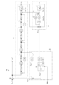
- FIG. 11 is a block diagram showing the configuration of the current control processing section 35 (see FIG. 2). As shown in FIG. 11 , the current control processing section 35 includes a voltage command value calculation section 81 , a coordinate conversion section 82 , a PWM conversion section 83 and a coordinate conversion section 84 .
- the voltage command value calculation unit 81 calculates smoothed non-interference voltages V d-dcpl-flt * and V q- dcpl-flt * by processing the non-interference voltages V d-dcpl * and V q-dcpl * with a low-pass filter.
- the voltage command value calculation unit 81 calculates the d-axis voltage command value V d * and the q-axis voltage command value V q * (hereinafter referred to as the dq-axis voltage command value V d * , V q * ) .
- the dq-axis currents i d and i q are calculated by the coordinate conversion section 84 .
- the coordinate conversion unit 82 converts the dq-axis voltage command values V d * and V q * into voltage command values for each of the UVW phases (hereinafter referred to as three-phase voltage command values V u * , V v * and V w * ) based on the rotor phase ⁇ of the motor 10 according to the following equation (22).
- PWM converter 83 generates PWM signals D uu * , D ul * , D vu * , D vl *, D wu * , D wl * , which are drive signals for switching elements of inverter 12, according to three-phase voltage command values V u * , V v * , V w * .
- the motor 10 is controlled to output the motor torque Tm according to the sixth torque target value Tm6 * .
- a coordinate conversion unit 84 calculates a W-phase current iw based on the U-phase current iu and the V-phase current iv detected by the current sensor 24 . Then, the coordinate conversion unit 84 converts these currents i u , iv and i w into dq axis currents id and iq using the rotor phase ⁇ of the motor 10 according to the following equation (23). The dq-axis currents i d and i q are used in the voltage command value calculator 81 as described above.
- the input processing unit 31 includes a motor rotation speed calculation unit 85 .
- a motor rotation speed calculator 85 calculates a motor rotation speed ⁇ m based on the rotor phase ⁇ of the motor 10 .
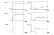
- FIG. 12 is a time chart showing the longitudinal acceleration AL1 and the like during towing.
- FIG. 12A is a time chart of the first torque target value T m1 * .
- FIG. 12B is a time chart of the sixth torque target value T m6 * .
- FIG. 12(C) is a time chart of the drive shaft torque Td .
- FIG. 12D is a time chart of the motor rotation speed ⁇ m .
- FIG. 12(E) is a time chart showing the longitudinal acceleration AL1 of the electric vehicle 100.
- FIG. FIG. 12F is a time chart showing the longitudinal acceleration AL2 of the articulated vehicle 102.
- FIG. 12A is a time chart of the first torque target value T m1 * .
- FIG. 12B is a time chart of the sixth torque target value T m6 * .
- FIG. 12(C) is a time chart of the drive shaft torque Td .
- FIG. 12D is a time chart of the motor rotation speed ⁇ m
- the solid lines show an example when the damping control according to the present embodiment is performed
- the dashed lines show an example when the damping control according to the comparative example is performed.
- the comparative example is an example in which the damping control section 33 does not perform the first damping correction processing by the longitudinal vibration suppressing section 36 .
- the first torque target value T m1 * is input in steps at time t 1 by the driver's accelerator operation.
- the sixth torque target value Tm6 * increases to a predetermined torque corresponding to the demand (accelerator opening Apo ) by accelerator operation.
- the drive shaft torque T d changes following the sixth torque target value T m6 * .
- the power transmission mechanism vibration is compensated for by the second damping correction process, so the change in the drive shaft torque Td is smooth.
- the motor rotation speed ⁇ m changes according to changes in the sixth torque target value T m6 * .
- This back-and-forth vibration continues after time t2 when the sixth torque target value Tm6 * converges to torque corresponding to the accelerator opening Apo .
- this back-and-forth oscillation continues even at time t3 after a sufficient amount of time has passed since the sixth torque target value Tm6 * converged.
- the first damping correction process is performed, so the longitudinal vibration between the electrically powered vehicle 100 and the coupled vehicle 102 is suppressed.
- FIG. 13 is a time chart showing the longitudinal acceleration AL1 and the like when the combined vehicle 102 is heavy. 13 shows a case in which the weight M2 of the articulated vehicle 102 is larger than in the case of FIG.
- the parameters shown in FIGS. 13A to 13F and the distinction between solid and broken lines are the same as in FIG.
- the weight M2 of the vehicle 102 is increased, so that the longitudinal vibrations of the electric vehicle 100 and the vehicle 102 are appropriately suppressed despite the change in the dynamic characteristics as described above.
- the first torque target value T m1 * is corrected by the first damping correction process to calculate the sixth torque target value T m6 * , which is the final torque command value, and the motor 10 is controlled according to this sixth torque target value T m6 * .
- the front-rear vibration that is peculiar to towing is suppressed.
- the effect of suppressing this longitudinal vibration can be obtained regardless of the size of the weight M2 of the towed vehicle 102 or the like.
- the torque rise and smooth acceleration required by the vehicle operation can be achieved regardless of the weight M2 of the coupled vehicle 102.
- the damping control unit 33 is composed of the longitudinal vibration suppressing unit 36 and the power transmission mechanism vibration suppressing unit 37, and the compensation of the longitudinal vibration peculiar to towing and the compensation of the power transmission mechanism vibration are performed separately, respectively, but the present invention is not limited to this.
- the damping control section 33 may be configured to substantially integrally perform compensation for longitudinal vibrations unique to towing and compensation for power transmission mechanism vibrations.
- a second embodiment in which the longitudinal vibration suppressing section 36 and the feedforward compensating section 64 (see FIG. 9) that is part of the power transmission mechanism vibration suppressing section 37 are integrally configured will be described below.
- FIG. 14 is a block diagram showing a partial configuration of the damping control section 33 in the second embodiment.
- the damping control section 33 of the second embodiment does not explicitly have the longitudinal vibration suppressing section 36 of the first embodiment. Therefore, in the damping control section 33 of the second embodiment, the feedforward compensation section 64 is configured to directly calculate the fourth target torque value Tm4 * based on the first target torque value Tm1 * .
- the feedforward compensation unit 64 of the second embodiment includes a vehicle model of the electric vehicle 100 (hereinafter referred to as an electric vehicle model 91), a model of the connected vehicle 102 connected to the connection unit 101 (hereinafter referred to as a connected vehicle model 92), a compensation torque calculation unit 93, and a damping correction processing unit 94.
- the electric vehicle model 91 calculates an estimated value of the motor torque Tm corresponding to the fourth target torque value Tm4 * (hereinafter simply referred to as torque estimated value Tm ⁇ ) based on the fourth target torque value Tm4 * (previous value) that is the output of the feedforward compensator 64.
- the electric vehicle model 91 is basically configured according to Equations (2) to (7), which are equations of motion of the electric vehicle 100 .
- the electric vehicle model 91 is configured to calculate the vehicle body speed v1 of the electric vehicle 100 using the force f12 acting between the electric vehicle 100 and the connected vehicle 102 based on equations (8) to (11). In this embodiment, the force f 12 is calculated in the articulated vehicle model 92 .
- the weight M1 of the electric vehicle 100 used in the process of calculating the vehicle body speed v1 of the electric vehicle 100 is calculated by a configuration similar to that of the electric vehicle weight calculator 42 of the first embodiment. That is, the weight M1 of the electric vehicle 100 used in the electric vehicle model 91 is a variable parameter.
- the estimated torque value T m ⁇ is input to the compensation torque calculator 93 .
- Vehicle speed v 1 is input to articulated vehicle model 92 .
- Articulated vehicle model 92 is configured to calculate vehicle body speed v2 of articulated vehicle 102 according to equations (8)-(11). Specifically, the vehicle speed v2 of the coupled vehicle 102 is calculated based on the deviation between the vehicle speed v1 of the electrically powered vehicle 100 and the vehicle speed v2 of the coupled vehicle 102, that is, the relative vehicle speed ⁇ v12 between the electrically powered vehicle 100 and the coupled vehicle 102. In calculating the relative vehicle speed ⁇ v12 , the vehicle speed v1 of the electric vehicle 100 is obtained from the electric vehicle model 91, and the previous value calculated by the connected vehicle model 92 is used as the vehicle speed v2 of the connected vehicle 102.
- the viscous characteristic CF and the elastic characteristic KF which are the mechanical characteristics of the connecting portion 101, are used to calculate the vehicle body speed v2 of the connected vehicle 102.
- FIG. Therefore, the dynamic characteristics of the connection portion 101 to which the articulated vehicle 102 is connected are substantially reflected in the value of the vehicle body speed v2 of the articulated vehicle 102 .
- the weight M2 of the articulated vehicle 102 used in the process of calculating the vehicle body speed v2 of the articulated vehicle 102 is calculated by the same configuration as the electric vehicle weight calculation unit 42, the gross weight calculation unit 41, and the connection vehicle weight calculation unit 43 of the first embodiment. That is, the weight M2 of articulated vehicle 102 used in articulated vehicle model 92 is a variable parameter.
- the force f 12 calculated in the process of calculating the vehicle speed v 2 is input to the electric vehicle model 91 .
- the relative vehicle speed ⁇ v 12 is input to the compensation torque calculator 93 .
- the relative vehicle speed ⁇ v12 substantially reflects the dynamic characteristics of the connection portion 101 to which the articulated vehicle 102 is connected via the vehicle body speed v2 of the articulated vehicle 102 .
- the compensating torque calculator 93 calculates a first compensating torque T FF1 * by multiplying the estimated torque value T m ⁇ by a predetermined gain K 1 that is determined in advance through experiments, simulations, or the like.
- the first compensating torque T FF1 * precompensates for the torque corresponding to the power transmission mechanism vibration.
- the compensating torque calculator 93 calculates a second compensating torque T FF2 * based on the relative vehicle speed ⁇ v12 .
- the second compensating torque T FF2 * preliminarily compensates for the torque corresponding to the longitudinal vibration caused by the connection of the connected vehicle 102 to the connecting portion 101 . More specifically, when the coupled vehicle 102 is coupled to the coupling portion 101, the compensating torque calculating portion 93 multiplies the relative vehicle speed ⁇ v 12 by a predetermined gain K2 determined in advance by experiments, simulations, or the like, and sets the value as the second compensating torque T FF2 * . On the other hand, when the connected vehicle 102 is not connected to the connection portion 101, the compensation torque calculation portion 93 sets the fixed value zero (“0”) as the second compensation torque T FF2 * .
- the switching of the second compensating torque T FF2 * is performed by the second compensating torque switching unit 95 based on the traction travel signal SW T. That is, when the second compensating torque switching unit 95 determines that the coupled vehicle 102 is coupled to the coupling unit 101 based on the traction travel signal SWT , the second compensating torque T FF2 * becomes a value based on the relative vehicle speed ⁇ v 12 . On the other hand, when the second compensating torque switching unit 95 determines that the coupled vehicle 102 is coupled to the coupling unit 101 based on the traction travel signal SWT , the second compensating torque T FF2 * is zero.
- the compensating torque calculator 93 calculates the third compensating torque TFF3 * by adding the first compensating torque TFF1 * and the second compensating torque TFF2 * calculated as described above. Therefore, the third compensating torque T FF3 * is, in principle, a torque for precompensating for the vibration of the power transmission mechanism, but when the connecting vehicle 102 is connected to the connecting portion 101, it further includes a torque for precompensating for the longitudinal vibration peculiar to towing.
- the third compensating torque T FF3 * is input to the damping correction processing section 94 .
- the damping correction processing unit 94 calculates a fourth target torque value Tm4 * by correcting the first target torque value Tm1 * using the third compensating torque TFF3 * . Then, when the articulated vehicle 102 is connected to the connecting portion 101, the correction processing performed by the damping correction processing portion 94 is substantially correction processing including the first damping correction processing and feedforward compensation of the first embodiment. Therefore, the fourth torque target value T m4 * calculated by the damping correction processing section 94 is substantially the same value as the fourth torque target value T m4 * output by the feedforward compensation section 64 of the first embodiment. Therefore, the fourth torque target value T m4 * becomes the sixth torque target value T m6 * by the feedback compensator 65 and the adder 66 as in the first embodiment, and is used as the final torque command value.
- the longitudinal vibration suppressing section 36 and the feedforward compensating section 64 of the first embodiment can be configured integrally.
- the fourth torque target value T m4 * output by the feedforward compensator 64 of the second embodiment, which integrates these components, is substantially the same as the fourth torque target value T m4 * of the first embodiment. Therefore, even when the longitudinal vibration suppressor 36 and the feedforward compensator 64 of the first embodiment are integrated as described above, the same functions and effects as those of the first embodiment can be obtained (see FIGS. 12 and 13).
- the feedforward compensator 64 of the second embodiment substantially performs damping control based on the transmission characteristics from the input of the first target torque value T m1 * to the output of the fourth target torque value T m4 * .
- the electric vehicle weight M1 and the connected vehicle weight M2 that constitute this transmission characteristic are variable parameters. Therefore, the control according to the second embodiment changes (adjusts) the contents of the transmission characteristics depending on whether or not the vehicle 102 is connected to the connecting portion 101, thereby suppressing the longitudinal vibrations peculiar to towing.
- modeling errors such as the transfer characteristic G p (s) may not be negligible. In such a situation, even if the correction process for suppressing the longitudinal vibration of the first embodiment or the second embodiment is performed, the longitudinal vibration may still occur.
- the third embodiment a configuration capable of suitably suppressing back-and-forth vibration without depending on errors included in known values of the elastic characteristic KF and viscous characteristic CF of the connecting portion 101 or on modeling errors will be described.
- FIG. 15 is a block diagram showing the configuration of the longitudinal vibration suppression section 36 in the third embodiment.
- the longitudinal acceleration AL1 is input to the natural vibration suppressing portion 44 of the longitudinal vibration suppressing portion 36 of the third embodiment.
- the natural vibration suppression unit 44 uses the electric vehicle weight M 1 , the coupled vehicle weight M 2 , the viscous characteristic C F and the elastic characteristic K F that are the mechanical characteristics of the coupling unit 101, and the longitudinal acceleration AL1 to perform the first damping correction process on the first torque target value T m1 * .
- the longitudinal acceleration AL1 is configured in the same manner as the longitudinal vibration suppressing portion 36 of the first embodiment.
- FIG. 16 is a block diagram showing the configuration of the natural vibration suppressing section 44 in the third embodiment.
- the natural vibration suppression unit 44 of the third embodiment includes a change rate calculation unit 301, a reference response calculation unit 302, a difference calculation unit 303, a feature amount calculation unit 304, a dynamic characteristic setting unit 305, and a first vibration suppression correction processing unit 306.
- the change rate calculator 301 calculates the rate of change of the motor torque Tm or a parameter corresponding to the rate of change of the motor torque Tm . Thereby, change rate calculation unit 301 determines a driving scene in which longitudinal vibration is likely to occur.
- the change rate calculation unit 301 calculates the amount of change in the first torque target value T m1 * in a predetermined time (for example, one control cycle), that is, the time change rate of the first torque target value T m1 * (hereinafter simply referred to as the change rate ⁇ T m1 * of the first torque target value T m1 * ). More specifically, the change rate calculator 301 holds the previous value T m1z * (not shown) of the first torque target value T m1 * .
- the change rate calculation unit 301 compares the current value and the previous value T m1z * of the first torque target value T m1 * , or calculates the difference between the current value and the previous value T m1z * of the first torque target value T m1 * , thereby calculating the rate of change ⁇ T m1 * of the first torque target value T m1 * .
- the change rate ⁇ T m1 * of the first torque target value T m1 * is a parameter that substantially represents the change rate (time change rate) of the motor torque T m .
- change rate calculation section 301 determines a driving scene in which longitudinal vibration is likely to occur based on change rate ⁇ T m1 * of first torque target value T m1 * . Specifically, the greater the rate of change ⁇ T m1 * of the first torque target value T m1 * , the more likely the longitudinal vibration will occur. Further, when the rate of change ⁇ T m1 * of the first torque target value T m1 * is large, if there is an error in the elastic characteristic KF or the viscous characteristic CF , or if there is a modeling error, the longitudinal vibration tends to remain even if the correction processing for suppressing the longitudinal vibration of the first embodiment or the second embodiment is performed.
- the change rate calculator 301 compares the change rate ⁇ T m1 * of the first torque target value T m1 * with the change rate threshold ⁇ T TH , and determines a driving scene in which the possibility of occurrence of longitudinal vibration is high when the change rate ⁇ T m1 * of the first torque target value T m1 * is greater than the change rate threshold ⁇ T TH .
- the change rate threshold ⁇ T TH is set in advance based on experiments, simulations, or the like with respect to the change rate ⁇ T m1 * of the first torque target value T m1 * .
- Change rate calculation unit 301 sets a dynamic characteristic calculation flag FLG according to the comparison result between change rate ⁇ T m1 * of first torque target value T m1 * and change rate threshold ⁇ T TH .
- the dynamic characteristic calculation flag FLG is an index that instructs to newly calculate the natural vibration frequency ⁇ t and the damping coefficient ⁇ t (specify the dynamic characteristic of the connecting portion 101) based on the longitudinal acceleration AL1 and the like.
- the dynamic characteristic calculation flag FLG is set to, for example, "1" or "0". When the flag FLG is "1", the natural vibration frequency ⁇ t and the damping coefficient ⁇ t are calculated based on the longitudinal acceleration AL1 and the like.
- Change rate calculation unit 301 sets dynamic characteristic calculation flag FLG to "1" when change rate ⁇ Tm1 * of first torque target value Tm1 * is greater than change rate threshold value ⁇ TTH .
- change rate calculation unit 301 sets dynamic characteristic calculation flag FLG to "0" when change rate ⁇ T m1 * of first torque target value T m1 * is equal to or less than change rate threshold value ⁇ T TH .
- Change rate calculation unit 301 inputs dynamic characteristic calculation flag FLG to, for example, reference response calculation unit 302 and the like.
- the reference response calculation unit 302 calculates a reference response A L1-ref of the longitudinal acceleration A L1 at least in a driving scene in which longitudinal vibration is highly likely to occur. In this embodiment, reference response calculation unit 302 calculates reference response A L1-ref of longitudinal acceleration A L1 when dynamic characteristic calculation flag FLG is "1".
- Reference response calculation unit 302 calculates reference response A L1-ref of longitudinal acceleration A L1 based on electric vehicle weight M 1 , coupled vehicle weight M 2 , and first torque target value T m1 * . Specifically, the reference response calculation unit 302 applies the reference transmission characteristic G pF-ref (s) represented by the following expression (24) to the first torque target value T m1 * , thereby calculating the reference response A L1-ref of the longitudinal acceleration A L1 according to the following expression (25). The reference response A L1 -ref of the longitudinal acceleration A L1 is input to the difference calculation section 303 .
- the reference transmission characteristic G pF-ref (s) represents a reference response from the motor torque T m to the driving force F.
- the reference response A L1-ref of the longitudinal acceleration A L1 is calculated in the same manner as the estimated longitudinal acceleration A L1 ⁇ , so the reference response A L1 -ref of the longitudinal acceleration A L1 is an estimated value.
- the above calculation method for the reference response A L1 -ref of the longitudinal acceleration A L1 is an example, and the reference response A L1-ref of the longitudinal acceleration A L1 can be calculated using, for example, the vehicle model represented by the above equation (19).
- a difference calculation unit 303 calculates a difference ⁇ A L1 between the longitudinal acceleration A L1 , which is the actual response, and the reference response A L1-ref .
- the difference calculator 303 calculates the difference ⁇ A L1 by subtracting the reference response A L1-ref from the longitudinal acceleration A L1 , which is the actual response. Further, difference calculation unit 303 continuously calculates difference ⁇ AL1 at least for a predetermined period PP after dynamic characteristic calculation flag FLG becomes “1”. That is, the difference ⁇ A L1 constitutes a data string that can change over time.
- the difference ⁇ AL1 calculated by the difference calculator 303 is input to the feature quantity calculator 304 .
- the “predetermined period PP” in which the difference ⁇ A L1 is calculated is a time interval at which time-series data of the difference ⁇ A L1 can be acquired to the extent that frequency analysis can be performed.
- the difference calculation unit 303 can perform filtering processing for extracting components in the specified frequency range from the output difference ⁇ A L1 . In this case, noise superimposed on the difference ⁇ AL1 (for example, noise caused by disturbance or the like) is removed, so that the longitudinal vibration suppression accuracy is improved.
- Feature amount calculation unit 304 identifies the dynamic characteristics of connection portion 101 to which connection vehicle 102 is connected by calculating a feature amount of longitudinal vibration caused by connection of connection vehicle 102 to connection portion 101 .
- the feature amount calculation unit 304 calculates the characteristic amount of longitudinal vibration, the natural vibration frequency ⁇ t and the damping coefficient ⁇ t , based on the difference ⁇ A L1 between the longitudinal acceleration A L1 , which is the actual response, and the reference response A L1-ref . That is, the feature amount calculation unit 304 holds the difference ⁇ A L1 for the predetermined period PP, and calculates the natural vibration frequency ⁇ t and the damping coefficient ⁇ t based on the time-series data.
- the feature amount calculation unit 304 can calculate the natural vibration frequency ⁇ t and the damping coefficient ⁇ t by subjecting the time-series data of the difference ⁇ A L1 to frequency analysis such as FFT (Fast Fourier Transform). In this embodiment, the feature amount calculator 304 simply calculates the natural vibration frequency ⁇ t and the damping coefficient ⁇ t based on the number of peaks (or bottoms) formed by the difference ⁇ A L1 of the predetermined period PP and the change in amplitude.
- FFT Fast Fourier Transform
- the characteristic amount calculator 304 does not use the viscous characteristic C F and the elastic characteristic K F of the connecting portion 101 to calculate the natural vibration frequency ⁇ t and the damping coefficient ⁇ t . That is, the feature quantity calculation unit 304 specifies the dynamic characteristics of the connecting part 101 by calculating the natural vibration frequency ⁇ t and the damping coefficient ⁇ t , which are the feature quantities of the longitudinal vibration, using a method different from that of the feature quantity calculation unit 62 of the first embodiment. The natural vibration frequency ⁇ t and the damping coefficient ⁇ t calculated by the feature amount calculation unit 304 are input to the dynamic characteristic setting unit 305 .
- the feature amount calculation unit 304 compares the difference ⁇ A L1 with the acceleration threshold ⁇ A TH . Then, when the difference ⁇ A L1 is greater than the acceleration threshold ⁇ A TH , the feature amount calculation unit 304 holds the time-series data of the difference ⁇ A L1 , and calculates the natural vibration frequency ⁇ t and the damping coefficient ⁇ t based on the time-series data of the difference ⁇ A L1 .
- the feature amount calculation unit 304 calculates a new natural vibration frequency ⁇ t and damping coefficient ⁇ t based on the time-series data of the difference ⁇ A L1 .
- the feature amount calculation unit 304 determines that even if longitudinal vibration occurs, the scene can be substantially ignored.
- the feature amount calculation unit 304 sets (resets) the dynamic characteristic calculation flag FLG to "0" and does not calculate a new natural vibration frequency ⁇ t and damping coefficient ⁇ t based on the difference ⁇ A L1 .
- the acceleration threshold ⁇ A TH is determined in advance by experiments, simulations, or the like.
- the dynamic characteristic setting unit 305 sets the natural vibration frequency ⁇ t and the damping coefficient ⁇ t to be finally used as the dynamic characteristic of the coupling unit 101 to the first damping correction processing unit 306 .
- an initial value ⁇ t0 (not shown) of the natural vibration frequency ⁇ t and an initial value ⁇ t0 (not shown) of the damping coefficient ⁇ t are predetermined. Therefore, when the dynamic characteristic calculation flag FLG does not become “1” and the feature amount calculation unit 304 does not newly calculate the natural vibration frequency ⁇ t and the damping coefficient ⁇ t , the dynamic characteristic setting unit 305 sets the initial values ⁇ t0 and ⁇ t0 to the natural vibration frequency ⁇ t and the damping coefficient ⁇ t that are finally used as the dynamic characteristics of the coupling unit 101.
- the initial values ⁇ t0 and ⁇ t0 are set based on, for example, the viscous characteristic C F and elastic characteristic K F of the connecting portion 101, the vehicle model of the electric vehicle 100, and the like.
- the dynamic characteristic setting unit 305 compares the newly calculated natural vibration frequency ⁇ t and the damping coefficient ⁇ t with the existing constants.
- the existing constants are the natural vibration frequency ⁇ t and the damping coefficient ⁇ t already used as the dynamic characteristics of the connecting portion 101, for example, their previous values ⁇ tz and ⁇ tz (not shown).
- the previous values ⁇ tz and ⁇ tz of the natural vibration frequency ⁇ t and the damping coefficient ⁇ t are, for example, their initial values ⁇ t0 and ⁇ t0 .
- the dynamic characteristic setting unit 305 calculates the frequency deviation ⁇ t , which is the deviation between the natural vibration frequency ⁇ t newly calculated by the feature amount calculation unit 304 and the previous value ⁇ tz of the natural vibration frequency ⁇ t , and compares it with the frequency threshold ⁇ TH .
- the frequency threshold ⁇ TH is determined in advance by experiment, simulation, or the like. Then, when the frequency deviation ⁇ t is greater than the frequency threshold ⁇ TH , the dynamic characteristic setting unit 305 updates the natural vibration frequency ⁇ t used as the dynamic characteristic of the connecting unit 101 to the natural vibration frequency ⁇ t newly calculated by the feature amount calculation unit 304 .
- the dynamic characteristic setting unit 305 maintains the natural vibration frequency ⁇ t used as the dynamic characteristic of the connecting unit 101 at the previous value ⁇ tz . That is, the dynamic characteristic setting unit 305 updates the natural vibration frequency ⁇ t when the natural vibration frequency ⁇ t deviates from the existing constant by a predetermined amount or more.
- the dynamic characteristic setting unit 305 calculates the damping coefficient deviation ⁇ t , which is the difference between the damping coefficient ⁇ t newly calculated by the feature quantity calculating unit 304 and the previous value ⁇ tz of the damping coefficient ⁇ t , and compares it with the damping coefficient threshold ⁇ TH .
- the damping coefficient threshold ⁇ TH is determined in advance through experiments, simulations, or the like. Then, when the damping coefficient deviation ⁇ t is greater than the damping coefficient threshold ⁇ TH , the dynamic characteristic setting unit 305 updates the damping coefficient ⁇ t used as the dynamic characteristic of the connecting unit 101 to the damping coefficient ⁇ t newly calculated by the feature amount calculating unit 304 .
- the dynamic characteristic setting unit 305 maintains the damping coefficient ⁇ t used as the dynamic characteristic of the coupling unit 101 at the previous value ⁇ tz . That is, the dynamic characteristic setting unit 305 updates the damping coefficient ⁇ t when the damping coefficient ⁇ t deviates from the existing constant by a predetermined degree or more. Note that the natural vibration frequency ⁇ t and the damping coefficient ⁇ t can be updated or maintained independently of each other.
- the dynamic characteristic setting unit 305 limits the range of the natural vibration frequency ⁇ t that can be set. Specifically, the dynamic characteristic setting unit 305 defines an upper limit and a lower limit for the natural vibration frequency ⁇ t , and updates or maintains the natural vibration frequency ⁇ t within the range of the upper limit and the lower limit.
- the upper and lower limits of the natural vibration frequency ⁇ t define the range of the natural vibration frequency ⁇ t that can be realistically obtained during towing, and are determined in advance by experiments, simulations, or the like.
- dynamic characteristic setting section 305 limits the range of damping coefficient ⁇ t that can be set.
- the dynamic characteristic setting unit 305 defines an upper limit and a lower limit for the damping coefficient ⁇ t , and updates or maintains the damping coefficient ⁇ t within the range of the upper limit and the lower limit.
- the upper and lower limits of the damping coefficient ⁇ t define the range of the damping coefficient ⁇ t that can be realistically obtained during towing, and are determined in advance by experiments, simulations, or the like.
- the dynamic characteristic setting unit 305 limits the ranges of the natural vibration frequency ⁇ t and the damping coefficient ⁇ t that can be set to realistic ranges. As a result, even if there is an estimation error in the natural vibration frequency ⁇ t and the damping coefficient ⁇ t in the feature amount calculation unit 304, the behavior of the electric vehicle 100 will not become unexpectedly unstable due to the estimation error.
- the first damping correction processing section 306 is configured in the same manner as the first damping correction processing section 63 (see FIG. 8) of the first embodiment, except that the natural vibration frequency ⁇ t and the damping coefficient ⁇ t are set by the dynamic characteristic setting section 305 . That is, the first damping correction processing section 306 calculates the second torque target value T m2 * by correcting the first torque target value T m1 * based on the natural vibration frequency ⁇ t and the damping coefficient ⁇ t set by the dynamic characteristic setting section 305 .
- FIG. 17 is a flowchart for updating the natural vibration frequency and the like.
- the change rate calculator 301 calculates the change rate ⁇ T m1 * of the first torque target value T m1 *.
- change rate calculation unit 301 compares change rate ⁇ T m1 * of first torque target value T m1 * with change rate threshold ⁇ T TH to set dynamic characteristic calculation flag FLG.
- step S302 when the change rate ⁇ T m1 * of the first torque target value T m1 * is greater than the change rate threshold ⁇ T TH , the dynamic characteristic calculation flag FLG is set to "1", and the process proceeds to step S303.
- This is a driving scene in which there is a high possibility that longitudinal vibration will occur during towing.
- the change rate ⁇ T m1 * of the first torque target value T m1 * is equal to or less than the change rate threshold ⁇ T TH in step S302
- the natural vibration frequency ⁇ t and the damping coefficient ⁇ t are maintained at the previous values ⁇ tz and ⁇ tz , and the updating process shown in this flowchart ends.
- This is a driving scene in which longitudinal vibration is less likely to occur during towing.
- step S303 the reference response calculation unit 302 calculates a reference response A L1-ref of the longitudinal acceleration A L1 based on the electric vehicle weight M 1 , the coupled vehicle weight M 2 , and the first torque target value T m1 * .
- step S304 the difference calculation unit 303 calculates the difference ⁇ A L1 between the longitudinal acceleration A L1 , which is the actual response, and the reference response A L1-ref .
- step S305 the feature quantity calculation unit 304 compares the difference ⁇ A L1 with the acceleration threshold ⁇ A TH to determine whether or not significant longitudinal vibration occurs.
- step S305 when the difference ⁇ A L1 is equal to or less than the acceleration threshold ⁇ A TH and the generated longitudinal vibration is negligible, the natural vibration frequency ⁇ t and the damping coefficient ⁇ t are maintained at the previous values ⁇ tz and ⁇ tz , and the updating process shown in this flowchart ends.
- step S305 when the difference ⁇ A L1 is greater than the acceleration threshold ⁇ A TH in step S305, the process proceeds to step S306, and the feature amount calculation unit 304 holds the difference ⁇ A L1 in the predetermined period PP. Then, in step S307, the feature amount calculation unit 304 calculates a new natural vibration frequency ⁇ t and a new damping coefficient ⁇ t based on the held time-series data of the difference ⁇ A L1 .
- step S308 the dynamic characteristic setting unit 305 calculates the frequency deviation ⁇ t, which is the deviation between the current value of the natural vibration frequency ⁇ t calculated by the feature amount calculation unit 304 and the previous value ⁇ tz of the natural vibration frequency ⁇ t , and compares it with the frequency threshold ⁇ TH . If it is determined in step S308 that the frequency deviation ⁇ t is greater than the frequency threshold value ⁇ TH and that a non-negligible error has occurred in the natural vibration frequency ⁇ t , the process proceeds to step S309, and the dynamic characteristic setting unit 305 updates the natural vibration frequency ⁇ t of the connecting portion 101 to the new natural vibration frequency ⁇ t calculated by the feature amount calculation unit 304.
- step S308 if it is determined in step S308 that the frequency deviation .delta..omega.t is equal to or less than the frequency threshold value .delta..omega.TH and that there is almost no error in the natural vibration frequency .omega.t , step S309 is skipped.
- step S310 the dynamic characteristic setting unit 305 calculates the damping coefficient deviation ⁇ t , which is the deviation between the current value of the damping coefficient ⁇ t calculated by the feature amount calculating unit 304 and the previous value ⁇ tz of the damping coefficient ⁇ t, and compares it with the damping coefficient threshold ⁇ TH .
- step S310 If it is determined in step S310 that the damping coefficient deviation ⁇ t is greater than the damping coefficient threshold ⁇ TH and that a non-negligible error has occurred in the damping coefficient ⁇ t , the process proceeds to step S311, where the dynamic characteristic setting unit 305 updates the damping coefficient ⁇ t of the coupling unit 101 to the new damping coefficient ⁇ t calculated by the feature amount calculation unit 304.
- step S311 is skipped.
- FIG. 18 is a time chart showing the longitudinal acceleration AL1 and the like in a driving scene in which the natural vibration frequency ⁇ t and the like are updated.
- FIG. 18A shows the first torque target value T m1 * .
- FIG. 18(B) shows the second torque target value T m2 * .
- FIG. 18(C) shows the drive shaft torque Td .
- the broken line indicates the dynamic characteristic calculation flag FLG, and the solid line indicates the natural vibration frequency ⁇ t to be counted up.
- FIG. 18(E) shows the motor rotation speed ⁇ m .
- FIG. 18A shows the first torque target value T m1 * .
- FIG. 18(B) shows the second torque target value T m2 * .
- FIG. 18(C) shows the drive shaft torque Td .
- the broken line indicates the dynamic characteristic calculation flag FLG
- the solid line indicates the natural vibration frequency ⁇ t to be counted up.
- FIG. 18(E) shows the motor rotation speed ⁇ m
- FIG. 18F the solid line indicates the longitudinal acceleration A L1 (actual response) of the electric vehicle 100, and the dashed line indicates the reference response A L1-ref of the longitudinal acceleration A L1 .
- FIG. 18G for reference, the solid line indicates the longitudinal acceleration A L2 (actual response) of the articulated vehicle 102, and the dashed line indicates the reference response A L2-ref of the longitudinal acceleration A L2 .
- FIG. 18(H) shows the difference ⁇ A L1 between the longitudinal acceleration A L1 of the electric vehicle 100 and its reference response A L1-ref .
- the horizontal axis of each graph in FIG. 18 is time [s]. Further, time t1 is the start time of the accelerator operation by the driver, and time t2 is the time after the predetermined period PP has elapsed from time t1 .
- the first torque target value Tm1 * is ramp-input according to the amount of operation.
- the dynamic characteristic calculation flag FLG is set to "1".
- the second torque target value T m2 * and the drive shaft torque T d increase following the first torque target value T m1 * .
- the motor rotation speed ⁇ m generally increases with the lapse of time.
- vibration occurs in the longitudinal acceleration AL1 of the electric vehicle 100 .
- the longitudinal acceleration AL2 of the connected vehicle 102 also vibrates in response to the vibration of the longitudinal acceleration AL1 . That is, the electric vehicle 100 and the articulated vehicle 102 vibrate back and forth.
- the vibration of the longitudinal acceleration A L1 has an amplitude that cannot be ignored with respect to the reference response A L1-ref . Therefore, as shown in FIG. Therefore , the feature amount calculation unit 304 holds the time-series data of the difference ⁇ A L1 in the predetermined period PP, and, for example, as shown in FIG.
- the feature quantity calculator 304 obtains the damping coefficient ⁇ t of the longitudinal vibration based on the decrease in the amplitude of the difference ⁇ AL1 .
- the natural vibration frequency ⁇ t and the damping coefficient ⁇ t used as the dynamic characteristics of the connecting unit 101 are updated to the natural vibration frequency ⁇ t and the damping coefficient ⁇ t obtained by the feature amount calculation unit 304 .
- FIG. 19 is a time chart showing the longitudinal acceleration AL1 and the like after updating the natural vibration frequency ⁇ t and the like.
- FIG. 19(A) shows the first torque target value T m1 * .
- FIG. 19B shows the second torque target value T m2 * .
- FIG. 19(C) shows the drive shaft torque Td .
- the broken line indicates the dynamic characteristic calculation flag FLG, and the solid line indicates the natural vibration frequency ⁇ t to be counted up.
- FIG. 19(E) shows the motor rotation speed ⁇ m .
- the solid line indicates the longitudinal acceleration A L1 (actual response) of the electric vehicle 100, and the dashed line indicates the reference response A L1-ref of the longitudinal acceleration A L1 .
- FIG. 19(A) shows the first torque target value T m1 * .
- FIG. 19B shows the second torque target value T m2 * .
- FIG. 19(C) shows the drive shaft torque Td .
- the broken line indicates the dynamic characteristic calculation flag
- FIG. 19G for reference, the solid line indicates the longitudinal acceleration A L2 (actual response) of the articulated vehicle 102, and the dashed line indicates the reference response A L2-ref of the longitudinal acceleration A L2 .
- FIG. 19(H) shows the difference ⁇ A L1 between the longitudinal acceleration A L1 of the electric vehicle 100 and its reference response A L1-ref .
- the horizontal axis of each graph in FIG. 19 is time [s]. Further, time t3 is the time when the driver starts operating the accelerator, and time t4 is the time after the predetermined period PP has elapsed from time t3 .
- the vibration of the longitudinal acceleration AL1 of the electric vehicle 100 is suppressed by updating the natural vibration frequency ⁇ t and the like.
- the vibration of the longitudinal acceleration AL2 of the articulated vehicle 102 is also suppressed. Therefore, as shown in FIG. 19(H), the difference ⁇ A L1 has no significant amplitude. Therefore, the dynamic characteristic calculation flag FLG is reset by the feature amount calculation unit 304 and set to "0" at least from time t3 to time t4 .
- the feature amount calculation unit 304 does not calculate a new natural vibration frequency ⁇ t and damping coefficient ⁇ t based on the difference ⁇ A L1 , and the natural vibration frequency ⁇ t and damping coefficient ⁇ t used as the dynamic characteristics of the coupling unit 101 are maintained at the previous values ⁇ tz and ⁇ tz . As a result, back-and-forth vibrations of electric vehicle 100 and coupled vehicle 102 are appropriately suppressed even after that.
- the natural vibration frequency ⁇ t and the damping coefficient ⁇ t which are the dynamic characteristics of the coupling portion 101, are calculated based on the difference ⁇ A L1 between the longitudinal acceleration A L1 , which is the actual response, and the reference response A L1-ref . Then, the first torque target value T m1 * is corrected based on the natural vibration frequency ⁇ t and the damping coefficient ⁇ t calculated based on this difference ⁇ A L1 .
- the longitudinal vibrations of the electric vehicle 100 and the articulated vehicle 102 are appropriately suppressed even when there is an error in the known values of the mechanical properties (the viscous property C F , the elastic property K F , etc.) of the connecting portion 101 or the modeling error of the vehicle model.
- control according to the third embodiment similarly to the first embodiment, the natural vibration frequency ⁇ t and the damping coefficient ⁇ t are directly calculated, and the compensation for the longitudinal vibration peculiar to towing and the compensation for the power transmission mechanism vibration are performed separately.
- the control according to the third embodiment can also be implemented in a configuration in which the compensation for the longitudinal vibration peculiar to towing and the compensation for the power transmission mechanism vibration are substantially integrally performed.
- FIG. 20 is a block diagram showing a partial configuration of the damping control section 33 when compensation for longitudinal vibrations peculiar to towing and compensation for power transmission mechanism vibrations are substantially integrally performed.
- the feedforward compensator 64 is specifically composed of an electric vehicle model 91 , a coupled vehicle model 92 , a compensation torque calculator 93 , and a damping correction processor 94 . That is, the overall configuration is similar to that of the second embodiment.
- the vibration suppression control unit 33 feedforward compensation unit 64 performs the control of the third embodiment, as shown in FIG. 20, the viscosity characteristic C F and the elastic characteristic K F , the electric vehicle weight M 1 , or the connected vehicle weight M 2 are made variable according to the natural vibration frequency ⁇ t and the damping coefficient ⁇ t set by the dynamic characteristic setting unit 305. That is, the dynamic characteristic setting unit 305 is configured to correct the viscous characteristic C F and elastic characteristic K F included in the coupled vehicle model 92, the electric vehicle weight M 1 included in the electric vehicle model 91, or the coupled vehicle weight M 2 included in the coupled vehicle model 92, according to the set natural vibration frequency ⁇ t and damping coefficient ⁇ t .
- the dynamic characteristic setting unit 305 can back-calculate the viscous characteristic CF and elastic characteristic KF , the electric vehicle weight M1 , or the connected vehicle weight M2 according to the natural vibration frequency ⁇ t and the damping coefficient ⁇ t to be set according to the equation of motion or the vehicle model described above.
- the dynamic characteristic setting unit 305 calculates an elastic characteristic K F (hereinafter referred to as a corrected elastic characteristic K F ′ (not shown)) corresponding to the natural vibration frequency ⁇ t to be set. Then, the dynamic characteristic setting unit 305 updates the elastic characteristic KF of the coupled vehicle model 92 to the corrected elastic characteristic KF '.
- a corrected elastic characteristic K F ′ (not shown)
- the dynamic characteristic setting unit 305 updates the elastic characteristic KF of the coupled vehicle model 92 to the corrected elastic characteristic KF '.
- the dynamic characteristic setting unit 305 calculates a viscosity characteristic C F (hereinafter referred to as corrected viscosity characteristic C F ′ (not shown)) corresponding to the damping coefficient ⁇ t to be set. Then, the dynamic characteristic setting unit 305 updates the viscosity characteristic C F of the coupled vehicle model 92 to the corrected viscosity characteristic C F ′.
- corrected viscosity characteristic C F ′ hereinafter referred to as corrected viscosity characteristic C F ′ (not shown)
- the dynamic characteristic setting unit 305 updates the elastic characteristic KF to the corrected elastic characteristic KF ' when updating the natural vibration frequency ⁇ t as described above. Further, since the damping coefficient ⁇ t is a parameter directly related to the viscosity characteristic CF , it is particularly preferable that the dynamic characteristic setting unit 305 updates the viscosity characteristic CF to the corrected viscosity characteristic CF ' when updating the damping coefficient ⁇ t as described above.
- the damping control unit 33 that substantially integrally compensates for the longitudinal vibration peculiar to towing and the compensation for the power transmission mechanism vibration, the relative vehicle speed ⁇ v 12 that reflects the natural vibration frequency ⁇ t and the damping coefficient ⁇ t to be set should be obtained. Therefore, instead of directly updating the elastic characteristic KF and the viscous characteristic CF , other parameters may be updated according to the natural vibration frequency ⁇ t and the damping coefficient ⁇ t to be set.
- the dynamic characteristic setting unit 305 can calculate an electric vehicle weight M 1 (hereinafter referred to as a corrected electric vehicle weight M 1 ′ (not shown)) corresponding to the natural vibration frequency ⁇ t or the damping coefficient ⁇ t to be set, and update the electric vehicle weight M 1 included in the electric vehicle model 91 to the corrected electric vehicle weight M 1 ′.
- the dynamic characteristic setting unit 305 can calculate the combined vehicle weight M 2 (hereinafter referred to as corrected combined vehicle weight M 2 ' (not shown)) according to the natural vibration frequency ⁇ t or the damping coefficient ⁇ t to be set, and update the combined vehicle weight M 2 included in the combined vehicle model 92 to the corrected combined vehicle weight M 2 '.
- the dynamic characteristic setting unit 305 can calculate two or more parameters among the corrected elastic characteristic K F ', the corrected viscous characteristic C F ', the corrected electric vehicle weight M 1 ', and the corrected coupled vehicle weight M 2 ' according to the natural vibration frequency ⁇ t or the damping coefficient ⁇ t to be set, and can update a plurality of corresponding parameters.
- the dynamic characteristic setting unit 305 preferably corrects the elastic characteristic KF at least based on the natural vibration frequency ⁇ t to be set. More preferably, the dynamic characteristic setting unit 305 corrects the elastic characteristic KF and the viscous characteristic CF based on the natural vibration frequency ⁇ t and the damping coefficient ⁇ t to be set.
- the third embodiment may be implemented alone instead of the first or second embodiment, as described above. However, the third embodiment can be implemented together with the first embodiment or the second embodiment.
- the initial values ⁇ t0 and ⁇ t0 of the natural vibration frequency ⁇ t and the damping coefficient ⁇ t in the third embodiment may be changed to the natural vibration frequency ⁇ t and the damping coefficient ⁇ t calculated by the feature amount calculation unit 62 of the first embodiment.
- the electric vehicle weight M 1 and the coupled vehicle weight M 2 may be set according to the respective estimation results as in the second embodiment, and then the elastic characteristic K F , the viscous characteristic C F , the electric vehicle weight M 1 , or the coupled vehicle weight M 2 may be updated according to the natural vibration frequency ⁇ t and the damping coefficient ⁇ t to be set.
- the state in which the longitudinal vibration is suppressed by the control of the first embodiment or the second embodiment is the standard state.
- the control according to the third embodiment particularly accurately suppresses (compensates for) the longitudinal vibrations that remain due to errors in the known values of the elastic characteristic KF and the viscous characteristic CF , or modeling errors of the electric vehicle 100 or the like. Therefore, when the control of the electric vehicle 100 according to the third embodiment is performed together with the control of the first embodiment or the second embodiment, the longitudinal vibrations of the electric vehicle 100 and the articulated vehicle 102 can be suppressed particularly favorably.
- the electric vehicle 100 has the traction switch 28 as described above, and whether or not the vehicle 102 is coupled to the coupling portion 101 is determined based on the traction signal SWT output by the traction switch 28, but the present invention is not limited to this.
- the traction travel switch 28 may be provided on the connecting portion 101 . In this case, when the articulated vehicle 102 is connected to the connecting portion 101, the traction travel signal SWT is automatically turned on regardless of the operation of the driver or the like.
- the electric vehicle 100 when the electric vehicle 100 is equipped with a rear camera for photographing the rear of the vehicle, the image captured by the rear camera may be used to recognize the articulated vehicle 102, and the motor controller 13 may determine whether or not the articulated vehicle 102 is connected to the connection portion 101 based on the recognition result. Further, when the weight M2 of the connected vehicle becomes a significant value, specifically, when the estimated weight M2 becomes equal to or greater than a predetermined threshold, the motor controller 13 may determine that the connected vehicle 102 is connected to the connection portion 101.
- the respective weights M 1 and M 2 of the electric vehicle 100 and the articulated vehicle 102 are estimated, but these values can also be defined values.
- the design weight M ini of the electric vehicle 100 can be used.
- the weight M2 of the connected vehicle 102 can be selectively manually input according to the type of vehicle. In this way, even if the weights M 1 and M 2 of the electric vehicle 100 and the articulated vehicle 102 are not estimated sequentially and are set to specified values, the same effect as in the above-described embodiments can be obtained for damping longitudinal vibrations peculiar to towing.
- longitudinal vibrations unique to towing can be suppressed particularly accurately.
- vibration of the power transmission mechanism is suppressed, but when the electric vehicle 100 does not have the drive shaft 22, suppression control of the vibration of the power transmission mechanism can be omitted. That is, the power transmission mechanism vibration suppressing portion 37 can be omitted.
- the viscous characteristic C F and the elastic characteristic K F are considered as mechanical characteristics of the connecting portion 101 in order to specify the dynamic characteristics of the connecting portion 101 to which the connected vehicle 102 is connected.
- the present invention is not limited to this. If the coupling 101 includes gears, the backlash of the gears can be taken into account. Thereby, the dynamic behavior of the coupling 101 to which the vehicle 102 is coupled is determined particularly accurately.
- the dynamic characteristics of the connecting portion 101 to which the connected vehicle 102 is connected are specified to the extent that the longitudinal vibration peculiar to towing can be easily and sufficiently suppressed.
- the dynamic characteristics of the connecting portion 101 are specified by the viscous characteristic CF and the elastic characteristic KF , but the dynamic characteristic of the connecting portion 101 may be specified by either the elastic characteristic KF or the viscous characteristic CF.
- the dynamic characteristic of the connecting portion 101 is specified at least by the elastic characteristic KF . That is, the first vibration damping correction process should at least suppress the component of the natural vibration frequency ⁇ t included in the first torque target value T m1 * based on the natural vibration frequency ⁇ t .
- the first damping correction process suppresses the component of the natural vibration frequency ⁇ t included in the first torque target value Tm1 * according to the damping coefficient ⁇ t based on the natural vibration frequency ⁇ t and the damping coefficient ⁇ t .
- the electric vehicle 100 calculates the first torque target value T m1 * based on the vehicle operation (accelerator operation, etc.) by the driver, but the present invention is not limited to this.
- the electric vehicle 100 may perform vehicle operation.
- the electrically powered vehicle 100 can calculate (determine) the first torque target value T m1 * by its own judgment, regardless of the vehicle operation by the driver. That is, the "vehicle operation" includes the operation of the electric vehicle 100 by its own judgment to set or change vehicle variables that can be set or changed by the driver's operation, in addition to the operation of the accelerator by the driver.
- the longitudinal vibrations of the electrically powered vehicle 100 and the articulated vehicle 102 are relative and related. Therefore, the computation using the longitudinal acceleration AL1 of the electrically powered vehicle 100 can be replaced with the computation using the longitudinal acceleration AL2 of the articulated vehicle 102. Further, in each of the above-described embodiments, calculations using the longitudinal acceleration AL1 of the electric vehicle 100 can be replaced with calculations using the longitudinal acceleration AL1 of the electric vehicle 100 and the longitudinal acceleration AL2 of the connected vehicle 102 . However, depending on the specific articulated vehicle 102, it is not always possible to acquire the longitudinal acceleration AL2 , so it is preferable to acquire the longitudinal acceleration AL1 of the electric vehicle 100 and use it as in each of the above embodiments.
- the control method for an electric vehicle is a control method for an electric vehicle 100 that has a motor 10 that is a drive source and a connection portion 101 that connects another vehicle, and runs by towing a connection vehicle 102 that is another vehicle connected to the connection portion 101.
- a basic torque target value (first torque target value T m1 * ) representing the torque (motor torque T m ) to be output by the motor 10 is calculated based on vehicle operation (accelerator opening A po etc.).
- the final torque command value (sixth torque target value T m6 * ), which is the final command value for the motor torque T m , is calculated by performing correction processing (first damping correction processing) on the basic torque target value to suppress the longitudinal vibration component generated in the electric vehicle 100 due to the connection of the connection vehicle 102 to the connection portion 101. Then, the motor 10 is controlled based on this final torque command value.
- the dynamic characteristics of the connection portion 101 to which the connection vehicle 102 is connected are specified based on the weight of the electric vehicle 100 (electric vehicle weight M 1 ), the weight of the connection vehicle 102 (connection vehicle weight M 2 ), and the mechanical characteristics (viscous characteristic C F and elastic characteristic K F ) of the connection portion 101 .
- the dynamic characteristics of the connection portion 101 to which the connection vehicle 102 is connected are specified based on the electric vehicle weight M 1 , the connection vehicle weight M 2 , and the mechanical characteristics of the connection portion 101.
- the mechanical properties of the connecting portion 101 include at least the viscous property C F and the elastic property K F of the connecting portion 101 . That is, at least the viscous characteristic C F and the elastic characteristic K F of the connecting part 101 are taken into account in order to specify the dynamic characteristic of the connecting part 101 to which the connected vehicle 102 is connected. In this way, by using at least the viscous characteristic CF and the elastic characteristic KF of the connecting portion 101, the dynamic characteristic of the connecting portion 101 to which the connected vehicle 102 is connected can be specified easily and accurately.
- the total weight M ⁇ of the electric vehicle 100 and the articulated vehicle 102 is estimated based on the longitudinal acceleration (longitudinal acceleration A L1 ) of the electric vehicle 100 . Further, the weight of the electric vehicle 100 (electric vehicle weight M 1 ) is estimated based on the suspension stroke amounts ST FL , ST FR , ST RL and ST RR of the electric vehicle 100 . By subtracting the weight of electric vehicle 100 (electric vehicle weight M 1 ) from total weight M ⁇ , the weight of connected vehicle 102 (connected vehicle weight M 2 ) is estimated.
- the articulated vehicle weight M 2 varies depending on the particular articulated vehicle 102 . Therefore, as described above, by sequentially estimating the electric vehicle weight M1 and the coupled vehicle weight M2 during towing, the longitudinal vibrations unique to towing can be suppressed accurately regardless of the specific coupled vehicle 102.
- connection portion 101 it is determined whether or not the connection portion 101 is connected to the connection vehicle 102 . Then, when it is determined that the articulated vehicle 102 is not connected to the connecting portion 101, correction processing for suppressing the longitudinal vibration peculiar to towing is not executed. On the other hand, when it is determined that the articulated vehicle 102 is connected to the connecting portion 101, a correction process is executed to suppress the longitudinal vibration peculiar to towing. In this manner, it is determined whether or not the vehicle is in a towed driving scene, and if necessary, correction processing is performed to suppress the peculiar back-and-forth vibration, thereby improving the control stability. Also, the load such as computation is reduced.
- the natural vibration frequency ⁇ t of the longitudinal vibration component is calculated based on the weight of the electric vehicle 100 (electric vehicle weight M 1 ), the weight of the connected vehicle 102 (connected vehicle weight M 2 ), and the mechanical characteristics (viscous characteristic C F and elastic characteristic K F ) of the connecting portion 101. Then, the component of this natural vibration frequency ⁇ t included in the basic torque target value (first torque target value T m1 * ) is suppressed.
- first torque target value T m1 * By specifying the natural vibration frequency ⁇ t in this way, the longitudinal vibration that is peculiar to towing is suppressed particularly accurately.
- the damping coefficient ⁇ t of the longitudinal vibration component is calculated based on the weight of the electric vehicle 100 (electric vehicle weight M 1 ), the weight of the connected vehicle 102 (connected vehicle weight M 2 ), and the mechanical characteristics (viscous characteristic C F and elastic characteristic K F ) of the connecting portion 101. Then, the component of the natural vibration frequency ⁇ t included in the basic torque target value (first torque target value T m1 * ) is suppressed according to this damping coefficient ⁇ t . In this way, by suppressing the component of the natural vibration frequency ⁇ t in accordance with the damping coefficient ⁇ t , the longitudinal vibration peculiar to towing is suppressed particularly efficiently.
- the longitudinal vibration unique to towing is particularly preferably suppressed.
- the correction process (first damping correction process) for suppressing the longitudinal vibration peculiar to towing is performed by processing the basic torque target value (first torque target value T m1 * ) using a band-stop filter set such that the natural vibration frequency ⁇ t is the center frequency for suppression and the damping coefficient ( ⁇ in equation (20)) is 1 or more.
- the band stop filter set such that the natural vibration frequency ⁇ t is the center frequency for suppression and the damping coefficient ( ⁇ in equation (20)) is 1 or more.
- the relative vehicle speed ⁇ v 12 between the electric vehicle 100 and the articulated vehicle 102 is calculated based on the dynamic characteristics of the connection portion 101 to which the articulated vehicle 102 is connected. Further, based on the relative vehicle speed ⁇ v12 , a correction torque (second compensation torque TFF2 * ) corresponding to the longitudinal vibration component is calculated. Then, using this correction torque (second compensation torque T FF2 * ), the basic torque target value (first torque target value T m1 * ) is corrected.
- first torque target value T m1 * the basic torque target value
- second compensation torque T FF2 * the correction torque
- the correction process for suppressing the longitudinal vibration peculiar to the towing running is performed by calculating the natural vibration frequency ⁇ t and the damping coefficient ⁇ t of the longitudinal vibration component, or both the natural vibration frequency ⁇ t and the damping coefficient ⁇ t , based on the longitudinal acceleration (A L1 ) of the electric vehicle 100 . configured to identify Furthermore, this correction process (first damping correction process or damping correction process including the first damping correction process) is configured to suppress the component of the natural vibration frequency ⁇ t included in the basic torque target value (first torque target value T m1 * ).
- the electric vehicle 100 normally has a sensor for detecting the longitudinal acceleration AL1 , according to the method for controlling an electric vehicle according to the third embodiment and the modified example, in order to suppress the longitudinal vibration peculiar to towing, there is no need to additionally provide a new sensor or the like, and the longitudinal vibration can be accurately suppressed without increasing the cost.
- the correction processing (first vibration damping correction processing or vibration damping correction processing including the first vibration damping correction processing) that suppresses the longitudinal vibration peculiar to towing in particular is performed by calculating the natural vibration frequency ⁇ t and the damping coefficient ⁇ t of the longitudinal vibration component based on the longitudinal acceleration (longitudinal acceleration A L1 ) of the electric vehicle 100, thereby specifying the dynamic characteristics of the coupling portion 101 and determining the basic torque target value (first torque target value T) . m1 * ) is suppressed in accordance with the damping coefficient ⁇ t .
- the natural vibration frequency ⁇ t and the damping coefficient ⁇ t are specified based on the longitudinal acceleration (A L1 ) of the electric vehicle 100, and the component of the natural vibration frequency ⁇ t is suppressed according to the damping coefficient ⁇ t , even if the mechanical characteristics (K F , CF ) of the connecting portion 101 and the vehicle model of the electric vehicle 100 contain errors, the longitudinal vibration unique to towing is particularly accurately suppressed.
- the correction process (first vibration suppression correction process or vibration suppression correction process including the first vibration suppression correction process) that suppresses the longitudinal vibration that is peculiar to towing is configured to be executed at least when the rate of change ( ⁇ T m1 * ) of the basic torque target value (first torque target value T m1 * ) is greater than the predetermined threshold value ( ⁇ T TH ).
- a driving scene in which longitudinal vibration is likely to occur is determined based on the rate of change ⁇ T m1 * of the first torque target value T m1 * , and at least the first damping correction process is executed in such a driving scene.
- the correction process (first vibration damping correction process or vibration damping correction process including the first vibration damping correction process) that suppresses the longitudinal vibration peculiar to the towed running is performed by calculating the reference response A L1-ref of the longitudinal acceleration (A L1 ), and based on the difference ⁇ A L1 between the obtained longitudinal acceleration (A L1 ) and the reference response A L1-ref of the longitudinal acceleration (A L1 ). , to calculate the natural vibration frequency ⁇ t and the damping coefficient ⁇ t .
- the realistic and accurate natural vibration frequency ⁇ t and the damping coefficient ⁇ t can be estimated regardless of the known values of the elastic characteristic KF and the viscous characteristic CF , modeling errors, and the like.
- the longitudinal vibrations of electric vehicle 100 and articulated vehicle 102 are suppressed particularly appropriately. Note that when the control of the electric vehicle according to the third embodiment and the modified example is performed together with the control of the first embodiment or the second embodiment, the longitudinal vibration that remains even after the control of the first embodiment or the second embodiment is performed can be suppressed appropriately.
- the reference response A L1-ref of the longitudinal acceleration (A L1 ) is calculated based on the basic torque target value (first torque target value T m1 * ), the weight (M 1 ) of the electric vehicle 100, and the weight (M 2 ) of the articulated vehicle 102.
- the reference response A L1-ref of the longitudinal acceleration A L1 is calculated based on the first torque target value T m1 * and the estimated values of the electric vehicle weight M1 and the connected vehicle weight M2 . Therefore, the longitudinal vibrations of the electric vehicle 100 and the coupled vehicle 102 are particularly appropriately suppressed.
- the correction process (first vibration damping correction process or vibration damping correction process including the first vibration damping correction process) that suppresses the longitudinal vibration peculiar to the towing running is configured to calculate the natural vibration frequency ⁇ t and the damping coefficient ⁇ t by performing frequency analysis processing on the difference ⁇ A L1 between the obtained longitudinal acceleration (A L1 ) and the reference response A L1-ref of the longitudinal acceleration (A L1 ).
- the correction processing (first vibration suppression correction processing or vibration suppression correction processing including the first vibration suppression correction processing) that suppresses the longitudinal vibrations peculiar to the towing running is configured to update the dynamic characteristics when the dynamic characteristics ( ⁇ t , ⁇ t ) of the connecting portion 101 change more than the predetermined threshold values ( ⁇ TH , ⁇ TH ) with respect to the previous values ( ⁇ tz , ⁇ tz ).
- the correction process (first vibration suppression correction process or vibration suppression correction process including the first vibration suppression correction process) that suppresses the longitudinal vibration peculiar to towing is configured to limit the range of the natural vibration frequency ⁇ t and the damping coefficient ⁇ t that can be set within a predetermined range (the range of values that can actually be taken during towing).
- a predetermined range the range of values that can actually be taken during towing.
- the electric vehicle 100 normally has a sensor for detecting the longitudinal acceleration AL1 , according to the method for controlling an electric vehicle according to the third embodiment and the modified example, in order to suppress the longitudinal vibration peculiar to towing, there is no need to additionally provide a new sensor or the like, and the longitudinal vibration can be accurately suppressed without increasing the cost.
Landscapes
- Engineering & Computer Science (AREA)
- Power Engineering (AREA)
- Transportation (AREA)
- Mechanical Engineering (AREA)
- Electric Propulsion And Braking For Vehicles (AREA)
Priority Applications (4)
| Application Number | Priority Date | Filing Date | Title |
|---|---|---|---|
| JP2023575043A JP7726302B2 (ja) | 2022-01-18 | 2022-04-20 | 電動車両の制御方法、及び、電動車両の制御装置 |
| US18/727,600 US12330508B2 (en) | 2022-01-18 | 2022-04-20 | Control method for electric vehicle and control device for electric vehicle |
| EP22921965.4A EP4467384A4 (en) | 2022-01-18 | 2022-04-20 | METHOD FOR CONTROLLING AN ELECTRIC VEHICLE AND DEVICE FOR CONTROLLING AN ELECTRIC VEHICLE |
| CN202280088746.5A CN118541283B (zh) | 2022-01-18 | 2022-04-20 | 电动车辆的控制方法以及电动车辆的控制装置 |
Applications Claiming Priority (2)
| Application Number | Priority Date | Filing Date | Title |
|---|---|---|---|
| JP2022-006018 | 2022-01-18 | ||
| JP2022006018 | 2022-01-18 |
Publications (1)
| Publication Number | Publication Date |
|---|---|
| WO2023139810A1 true WO2023139810A1 (ja) | 2023-07-27 |
Family
ID=87348526
Family Applications (1)
| Application Number | Title | Priority Date | Filing Date |
|---|---|---|---|
| PCT/JP2022/018304 Ceased WO2023139810A1 (ja) | 2022-01-18 | 2022-04-20 | 電動車両の制御方法、及び、電動車両の制御装置 |
Country Status (5)
| Country | Link |
|---|---|
| US (1) | US12330508B2 (https=) |
| EP (1) | EP4467384A4 (https=) |
| JP (1) | JP7726302B2 (https=) |
| CN (1) | CN118541283B (https=) |
| WO (1) | WO2023139810A1 (https=) |
Citations (5)
| Publication number | Priority date | Publication date | Assignee | Title |
|---|---|---|---|---|
| US4222614A (en) * | 1979-02-22 | 1980-09-16 | Warner Electric Brake & Clutch Co. | Surge control for electrical trailer brakes |
| JP2003009566A (ja) | 2001-06-18 | 2003-01-10 | Nissan Motor Co Ltd | 電動モータを用いた車両の制振制御装置 |
| JP2004064906A (ja) * | 2002-07-30 | 2004-02-26 | Meidensha Corp | 電動車輛の制御方法 |
| JP2007110879A (ja) * | 2005-10-17 | 2007-04-26 | Hitachi Ltd | 電気車の駆動システム |
| WO2020194621A1 (ja) * | 2019-03-27 | 2020-10-01 | 日産自動車株式会社 | 電動車両の制御装置及び電動車両の制御方法 |
Family Cites Families (8)
| Publication number | Priority date | Publication date | Assignee | Title |
|---|---|---|---|---|
| ES2459870T3 (es) * | 2006-09-22 | 2014-05-12 | Central Japan Railway Company | Sistema de control de tracción de vehículo |
| JP6201210B2 (ja) * | 2013-09-24 | 2017-09-27 | 日立オートモティブシステムズ株式会社 | 電動車両の制御装置及び電動車両の制御方法 |
| KR101713734B1 (ko) * | 2015-10-06 | 2017-03-08 | 현대자동차 주식회사 | 하이브리드 차량의 제어 방법 및 장치 |
| JP6531946B2 (ja) * | 2015-10-09 | 2019-06-19 | 日立オートモティブシステムズ株式会社 | 電動車両の制御装置、電動車両の制御システム及び電動車両の制御方法 |
| US10167004B2 (en) * | 2015-12-18 | 2019-01-01 | General Electric Company | Sensor system |
| DE102019100017A1 (de) * | 2019-01-02 | 2020-07-02 | Wabco Gmbh | Anhängerfahrzeug und Anhängerbremssteuergerät sowie Verfahren und Software dafür |
| KR102634360B1 (ko) * | 2019-03-15 | 2024-02-08 | 현대자동차주식회사 | 전기자동차의 견인모드 제어 장치 및 그 방법 |
| JP6787507B1 (ja) * | 2020-01-23 | 2020-11-18 | トヨタ自動車株式会社 | 電気自動車 |
-
2022
- 2022-04-20 EP EP22921965.4A patent/EP4467384A4/en not_active Withdrawn
- 2022-04-20 WO PCT/JP2022/018304 patent/WO2023139810A1/ja not_active Ceased
- 2022-04-20 CN CN202280088746.5A patent/CN118541283B/zh active Active
- 2022-04-20 US US18/727,600 patent/US12330508B2/en active Active
- 2022-04-20 JP JP2023575043A patent/JP7726302B2/ja active Active
Patent Citations (5)
| Publication number | Priority date | Publication date | Assignee | Title |
|---|---|---|---|---|
| US4222614A (en) * | 1979-02-22 | 1980-09-16 | Warner Electric Brake & Clutch Co. | Surge control for electrical trailer brakes |
| JP2003009566A (ja) | 2001-06-18 | 2003-01-10 | Nissan Motor Co Ltd | 電動モータを用いた車両の制振制御装置 |
| JP2004064906A (ja) * | 2002-07-30 | 2004-02-26 | Meidensha Corp | 電動車輛の制御方法 |
| JP2007110879A (ja) * | 2005-10-17 | 2007-04-26 | Hitachi Ltd | 電気車の駆動システム |
| WO2020194621A1 (ja) * | 2019-03-27 | 2020-10-01 | 日産自動車株式会社 | 電動車両の制御装置及び電動車両の制御方法 |
Also Published As
| Publication number | Publication date |
|---|---|
| CN118541283B (zh) | 2025-10-28 |
| US20250091448A1 (en) | 2025-03-20 |
| CN118541283A (zh) | 2024-08-23 |
| JPWO2023139810A1 (https=) | 2023-07-27 |
| EP4467384A1 (en) | 2024-11-27 |
| US12330508B2 (en) | 2025-06-17 |
| JP7726302B2 (ja) | 2025-08-20 |
| EP4467384A4 (en) | 2025-04-09 |
Similar Documents
| Publication | Publication Date | Title |
|---|---|---|
| RU2699203C1 (ru) | Способ управления для электрического транспортного средства и устройство управления для электрического транспортного средства | |
| RU2737640C1 (ru) | Способ и устройство управления электродвигателем электрического транспортного средства | |
| JP5857781B2 (ja) | 電動モータを用いた車両の制振制御装置 | |
| US10752286B2 (en) | Steering control apparatus and steering control method | |
| JP6233420B2 (ja) | 電動車両の制御装置および電動車両の制御方法 | |
| JP5862436B2 (ja) | 電動車両の制御装置 | |
| JP5900609B2 (ja) | 電動車両の制御装置および電動車両の制御方法 | |
| EP3492305B1 (en) | Vehicle control method and control device | |
| JP2003009566A (ja) | 電動モータを用いた車両の制振制御装置 | |
| JP4419625B2 (ja) | 車両用制振制御装置および車両用制振制御方法 | |
| JP2017175853A (ja) | 電動車両の制御方法、及び、電動車両の制御装置 | |
| CN117836168A (zh) | 电动车辆的控制方法以及电动车辆的控制装置 | |
| JP6720714B2 (ja) | 電動車両の制御方法、及び電動車両の制御装置 | |
| JP5862792B2 (ja) | 電動車両のモータ制御装置および電動車両のモータ制御方法 | |
| WO2020194637A1 (ja) | 電動車両の制御方法、及び、制御装置 | |
| JP6686658B2 (ja) | 電動車両の制御方法、及び、電動車両の制御装置 | |
| JP6819081B2 (ja) | 電動車両の制御方法、及び、制御装置 | |
| JP2024011931A (ja) | 電動車両の制御方法、及び、電動車両の制御装置 | |
| WO2023139810A1 (ja) | 電動車両の制御方法、及び、電動車両の制御装置 | |
| JP4517693B2 (ja) | 車両用制振制御装置および車両用制振制御方法 | |
| JP6880675B2 (ja) | 電動車両の制御方法、及び、電動車両の制御装置 | |
| CN115800854A (zh) | 电机谐波转矩补偿方法、装置、电子设备及存储介质 | |
| WO2026028295A1 (ja) | 電動車両の制御方法、電動車両の制御システム |
Legal Events
| Date | Code | Title | Description |
|---|---|---|---|
| 121 | Ep: the epo has been informed by wipo that ep was designated in this application |
Ref document number: 22921965 Country of ref document: EP Kind code of ref document: A1 |
|
| WWE | Wipo information: entry into national phase |
Ref document number: 2023575043 Country of ref document: JP |
|
| WWE | Wipo information: entry into national phase |
Ref document number: 18727600 Country of ref document: US |
|
| WWE | Wipo information: entry into national phase |
Ref document number: 202280088746.5 Country of ref document: CN |
|
| WWE | Wipo information: entry into national phase |
Ref document number: 2022921965 Country of ref document: EP |
|
| NENP | Non-entry into the national phase |
Ref country code: DE |
|
| ENP | Entry into the national phase |
Ref document number: 2022921965 Country of ref document: EP Effective date: 20240819 |
|
| WWP | Wipo information: published in national office |
Ref document number: 18727600 Country of ref document: US |
|
| WWW | Wipo information: withdrawn in national office |
Ref document number: 2022921965 Country of ref document: EP |
|
| WWG | Wipo information: grant in national office |
Ref document number: 18727600 Country of ref document: US |
|
| WWG | Wipo information: grant in national office |
Ref document number: 202280088746.5 Country of ref document: CN |