WO2023139810A1 - Method for controlling electric vehicle and device for controlling electric vehicle - Google Patents
Method for controlling electric vehicle and device for controlling electric vehicle Download PDFInfo
- Publication number
- WO2023139810A1 WO2023139810A1 PCT/JP2022/018304 JP2022018304W WO2023139810A1 WO 2023139810 A1 WO2023139810 A1 WO 2023139810A1 JP 2022018304 W JP2022018304 W JP 2022018304W WO 2023139810 A1 WO2023139810 A1 WO 2023139810A1
- Authority
- WO
- WIPO (PCT)
- Prior art keywords
- electric vehicle
- vehicle
- torque
- target value
- control method
- Prior art date
Links
Images


Classifications
-
- B—PERFORMING OPERATIONS; TRANSPORTING
- B60—VEHICLES IN GENERAL
- B60L—PROPULSION OF ELECTRICALLY-PROPELLED VEHICLES; SUPPLYING ELECTRIC POWER FOR AUXILIARY EQUIPMENT OF ELECTRICALLY-PROPELLED VEHICLES; ELECTRODYNAMIC BRAKE SYSTEMS FOR VEHICLES IN GENERAL; MAGNETIC SUSPENSION OR LEVITATION FOR VEHICLES; MONITORING OPERATING VARIABLES OF ELECTRICALLY-PROPELLED VEHICLES; ELECTRIC SAFETY DEVICES FOR ELECTRICALLY-PROPELLED VEHICLES
- B60L15/00—Methods, circuits, or devices for controlling the traction-motor speed of electrically-propelled vehicles
- B60L15/20—Methods, circuits, or devices for controlling the traction-motor speed of electrically-propelled vehicles for control of the vehicle or its driving motor to achieve a desired performance, e.g. speed, torque, programmed variation of speed
-
- Y—GENERAL TAGGING OF NEW TECHNOLOGICAL DEVELOPMENTS; GENERAL TAGGING OF CROSS-SECTIONAL TECHNOLOGIES SPANNING OVER SEVERAL SECTIONS OF THE IPC; TECHNICAL SUBJECTS COVERED BY FORMER USPC CROSS-REFERENCE ART COLLECTIONS [XRACs] AND DIGESTS
- Y02—TECHNOLOGIES OR APPLICATIONS FOR MITIGATION OR ADAPTATION AGAINST CLIMATE CHANGE
- Y02T—CLIMATE CHANGE MITIGATION TECHNOLOGIES RELATED TO TRANSPORTATION
- Y02T10/00—Road transport of goods or passengers
- Y02T10/60—Other road transportation technologies with climate change mitigation effect
- Y02T10/72—Electric energy management in electromobility
Definitions
- the present invention relates to an electric vehicle control method and an electric vehicle control device.
- JP2003-009566A discloses a control method for suppressing vibrations occurring in an electric vehicle based on torque transmission characteristics of a power transmission mechanism connected between the output shaft of a motor and driving wheels.
- electric vehicles may tow other vehicles.
- the total weight of the towing electric vehicle and the towed other vehicle is the substantial vehicle weight of the electric vehicle. Therefore, when the electric vehicle is towed, the change in vehicle weight to be considered becomes a large change that cannot be ignored.
- the conventional damping control cannot provide sufficient damping effect.
- the torque transmission characteristics of the power transmission mechanism are usually determined by the structure of the power transmission mechanism, etc., and do not reflect the presence or absence of traction. Therefore, the conventional damping control cannot sufficiently suppress the vibration caused by the towing of other vehicles or the like. That is, when the electric vehicle is towed, the conventional damping control cannot provide a sufficient damping effect, and the electric vehicle vibrates. As a result, when the vehicle is towed, the electric vehicle may not be able to achieve a torque rise or smooth acceleration required by the vehicle operation.
- An object of the present invention is to provide an electric vehicle control method and an electric vehicle control apparatus that can achieve a rise in torque required by vehicle operation and smooth acceleration even when the electric vehicle is towed.
- An aspect of the present invention is a control method for an electric vehicle that has a motor that is a drive source and a connecting portion that connects another vehicle, and runs by towing a connected vehicle that is another vehicle that is connected to the connecting portion.
- a basic torque target value representing the torque to be output by the motor is calculated based on the vehicle operation. Further, based on the dynamic characteristics of the coupling portion to which the coupled vehicle is coupled, correction processing is performed on the basic torque target value to suppress the longitudinal vibration component that occurs in the electric vehicle due to the coupled vehicle being coupled to the coupling portion, thereby calculating the final torque command, which is the final command value for the torque. Then, the motor is controlled based on this final torque command value.
- FIG. 1 is an explanatory diagram showing a schematic configuration of an electric vehicle.
- FIG. 2 is a block diagram showing the configuration of the motor controller.
- FIG. 3 is a graph showing an example of an accelerator opening-torque table.
- FIG. 4 is an explanatory diagram showing a dynamic model of an electric vehicle in which a connected vehicle is connected to a connecting portion.
- FIG. 5 is a block diagram showing the configuration of the longitudinal vibration suppressing section.
- FIG. 6 is a block diagram showing the configuration of the gross weight calculator.
- FIG. 7 is a block diagram showing the configuration of the electric vehicle weight calculator.
- FIG. 8 is a block diagram showing the configuration of the natural vibration suppressing section.
- FIG. 9 is a block diagram showing the configuration of the power transmission mechanism vibration suppression unit.
- FIG. 1 is an explanatory diagram showing a schematic configuration of an electric vehicle.
- FIG. 2 is a block diagram showing the configuration of the motor controller.
- FIG. 3 is a graph showing an example of an accelerator opening-tor
- FIG. 10 is a graph showing transfer characteristics H 2 (s) used in the disturbance estimator.
- FIG. 11 is a block diagram showing the configuration of a current command value calculator and a current control processor.
- FIG. 12 is a time chart showing the longitudinal acceleration and the like during towing.
- FIG. 13 is a time chart showing longitudinal acceleration and the like when the weight of the connected vehicle is large.
- FIG. 14 is a block diagram showing a partial configuration of a damping control section in the second embodiment.
- FIG. 15 is a block diagram showing the configuration of the longitudinal vibration suppressing section in the third embodiment.
- FIG. 16 is a block diagram showing the configuration of the natural vibration suppression section in the third embodiment.
- FIG. 17 is a flowchart for updating the natural vibration frequency and the like.
- FIG. 18 is a time chart showing longitudinal acceleration and the like in a driving scene in which the natural vibration frequency and the like are updated.
- FIG. 19 is a time chart showing the longitudinal acceleration and the like after updating the natural vibration frequency and the like.
- FIG. 20 is a block diagram showing a partial configuration of the damping control unit when compensation for longitudinal vibrations peculiar to towing and compensation for power transmission mechanism vibrations are substantially integrally performed.
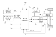
- FIG. 1 is an explanatory diagram showing a schematic configuration of an electric vehicle 100.
- the electric vehicle 100 can be connected to another vehicle or the like and can be towed to travel.
- the other vehicle or the like is, for example, a vehicle capable of self-propelled or a vehicle (trailer) that does not have self-propelled capability.
- the electric vehicle 100 functions as a towing vehicle that tows other vehicles or the like, but the electric vehicle 100 can travel without towing other vehicles or the like.
- the electric vehicle 100 includes a motor 10, a battery 11, an inverter 12, and a motor controller 13.
- Motor 10 is a drive source of electric vehicle 100 .
- Torque generated by the motor 10 (hereinafter referred to as motor torque Tm (not shown)) is transmitted to drive wheels 23 via a speed reducer 21 and a drive shaft 22 .
- the motor 10 can generate a regenerative braking force on the driving wheels 23 by so-called regenerative control when rotating together with the driving wheels 23 .
- the motor 10 recovers the kinetic energy of the electric vehicle 100 as electrical energy.
- the motor 10 is, for example, a three-phase AC synchronous motor. Currents i u , iv , and i w flowing through each phase of motor 10 can be detected using current sensors 24 .
- the rotor phase ⁇ of the motor 10 is detected using a rotation sensor 25 such as a resolver or encoder.
- the speed reducer 21 and the drive shaft 22 constitute a power transmission mechanism (torque transmission system) that transmits power (torque) from the motor 10 to the drive wheels 23 .
- Battery 11 supplies power to drive motor 10 via inverter 12 . Also, the battery 11 can be charged with regenerated electric power generated in the motor 10 by regenerative control. Battery 11 is a DC power supply.
- the DC voltage Vdc output by the battery 11 is detected by, for example, the voltage sensor 26 and obtained directly from the voltage sensor 26 or via a battery controller (not shown).
- the inverter 12 converts the DC power supplied from the battery 11 into AC power and supplies the AC power to the motor 10 .
- the inverter 12 converts AC regenerated power input from the motor 10 by regeneration control into DC power and inputs the DC power to the battery 11 .
- the inverter 12 is composed of a plurality of switching elements (not shown), and converts the DC power from the battery 11 into AC power by turning on/off these switching elements.
- inverter 12 converts AC regenerated power input from motor 10 into DC power by turning on/off switching elements. Two pairs of switching elements are provided for each phase of the motor 10 .
- the switching element is, for example, a power semiconductor element such as an IGBT (insulated gate bipolar transistor) or a MOS-FET (metal oxide semiconductor field effect transistor).
- the motor controller 13 generates a PWM signal (pulse width modulation signal) that is a drive signal for the inverter 12 based on various vehicle variables that are parameters representing the control state of the electric vehicle 100 or each part that configures the electric vehicle 100 .
- the motor controller 13 controls the motor 10 by driving the inverter 12 with the generated PWM signal.
- the motor controller 13 acquires or calculates the rotor phase ⁇ , currents i u , iv , i w , DC voltage V dc , longitudinal acceleration A L1 , accelerator opening A po , suspension stroke amounts ST FL , ST FR , ST RL , ST RR , traction signal SW T , etc. as vehicle variables.
- the longitudinal acceleration AL1 is acceleration in the longitudinal direction (longitudinal direction) of the electric vehicle 100, and is detected by, for example, an acceleration sensor (not shown). Also, the longitudinal acceleration AL1 may be obtained from a controller (not shown). Further, the accelerator opening Apo is a parameter representing the operation amount of the accelerator provided in the electric vehicle 100, and is detected by a sensor or the like (not shown). Accelerator opening degree A po represents a required amount of driving force (torque) for electric vehicle 100 according to vehicle operation.
- Suspension stroke amounts ST FL , ST FR , ST RL , and ST RR are stroke amounts of suspensions provided for the left front wheel, right front wheel, left rear wheel, and right rear wheel of electric vehicle 100, respectively.
- Suspension stroke amounts ST FL , ST FR , ST RL , and ST RR are detected by suspension stroke sensors 27 provided for each suspension.
- the front wheels of the electric vehicle 100 are driving wheels 23, and the rear wheels are driven wheels.
- the traction travel signal SWT is a signal output by the traction travel switch 28 .
- the towing switch 28 is a control mode changeover switch operated by the driver or the like when the electric vehicle 100 connects another vehicle to the connecting portion 101 (see FIG. 4) and tows the other vehicle.
- the connecting portion 101 is a member that connects another vehicle or the like, and is a towing member such as a so-called trailer hitch.
- another vehicle or the like a towed vehicle or the like that is connected to the connecting portion 101 and towed by the electric vehicle 100 is referred to as a "connected vehicle 102".
- the towing signal SWT is a criterion indicating whether or not the electric vehicle 100 is towing. Specifically, when the electric vehicle 100 tows the connected vehicle 102 and travels, the traction travel signal SWT is set to ON by operating the traction travel switch 28 . Based on the towing signal SWT , the motor controller 13 determines whether or not the connected vehicle 102 is connected to the connecting portion 101, that is, whether or not the vehicle is towed. Then, according to the determination result, motor controller 13 changes the content of damping control for suppressing vibrations occurring in electric vehicle 100 .
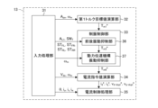
- FIG. 2 is a block diagram showing the configuration of the motor controller 13.
- the motor controller 13 is configured by one or a plurality of computers and is programmed to repeatedly execute the processing of each unit described below at a predetermined cycle.
- the motor controller 13 includes an input processing unit 31, a first torque target value calculation unit 32 (basic torque target value calculation unit), a damping control unit 33 (correction processing unit), a current command value calculation unit 34, and a current control processing unit 35.
- the input processing unit 31 acquires vehicle variables used for various controls and/or calculations executed by the motor controller 13, or executes input processing for calculation. For example, the input processing unit 31 acquires, as vehicle variables, the rotor phase ⁇ , currents i u and iv , DC voltage V dc , longitudinal acceleration A L1 , accelerator opening A po , suspension stroke amounts ST FL , ST FR , ST RL , and ST RR , and traction signal SW T.
- the input processing unit 31 calculates the rotor angular velocity ⁇ [rad/s] (electrical angular velocity) of the motor 10 by differentiating the rotor phase ⁇ (electrical angle).
- the input processing unit 31 divides the rotor angular velocity ⁇ by the pole logarithm of the motor 10 to calculate the rotation speed of the motor 10 (hereinafter referred to as motor rotation speed) ⁇ m [rad/s] (mechanical angular velocity).
- the input processing unit 31 may calculate the motor rotation speed N m [rpm] by multiplying the motor rotation speed ⁇ m by a unit conversion factor (60/2 ⁇ ).
- the current sensor 24 detects the U-phase current iu and the V-phase current iv . Therefore, the input processing unit 31 calculates the W-phase current iw using the U-phase current iu and the V-phase current iv based on the following equation (1).
- a first torque target value calculation unit 32 calculates a first torque target value T m1 * based on the accelerator opening A po and the motor rotation speed ⁇ m .
- the first torque target value T m1 * is a torque target value calculated based on vehicle operation and represents the torque (motor torque T m ) that the motor 10 should output. That is, the first torque target value T m1 * is a basic torque target value (basic torque target value) for generating the driving force required for electric vehicle 100 .
- FIG. 3 is a graph showing an example of an accelerator opening-torque table. As shown in FIG. 3, it is a table in which the accelerator opening A po and the motor rotation speed ⁇ m are associated in advance with the first torque target value T m1 * by experiments, simulations, or the like.
- the first torque target value calculation unit 32 calculates the first torque target value T m1 * by referring to this accelerator opening-torque table based on the accelerator opening A po and the motor rotation speed ⁇ m .
- Vibration suppression control unit 33 executes vibration suppression control processing for calculating a sixth target torque value T m6 * by correcting first target torque value T m1 * so as to suppress vibration occurring in electric vehicle 100.
- the sixth torque target value T m6 * is used as the final torque command value, which is the final command value for the torque to be output by the motor 10 .
- vibrations there are two types of vibrations that occur in the electric vehicle 100 .
- One is a vibration inherent to the connection of the vehicle 102 to the connection portion 101 when the electrically powered vehicle 100 tows the vehicle 102 and travels. This vibration occurs in the longitudinal direction of electric vehicle 100 .
- the vibration caused by the change in acceleration in the front-rear direction caused by the connection of the vehicle 102 to the connection portion 101 is referred to as the front-rear vibration.
- Another vibration is the vibration caused by transmitting the motor torque Tm to the drive wheels 23 through the power transmission mechanism.
- This vibration includes, for example, vibration caused by disturbance such as a road surface gradient, and vibration caused by gear backlash, torsion of the drive shaft 22, and the like.
- the vibration generated in the power transmission mechanism will be referred to as power transmission mechanism vibration.
- the damping control unit 33 includes a longitudinal vibration suppressing unit 36 and a power transmission mechanism vibration suppressing unit 37 in order to suppress these vibrations.
- the longitudinal vibration suppression unit 36 executes longitudinal vibration suppression processing.
- the longitudinal vibration suppression process is a process for suppressing longitudinal vibrations that occur when the vehicle 102 is towed based on the dynamic characteristics of the connecting portion 101 to which the vehicle 102 is coupled.
- the dynamic characteristics of the connecting portion 101 to which the articulated vehicle 102 is connected refer to temporal changes in movement of the connecting portion (including the connecting portion 101) caused by the articulated vehicle 102 being connected to the connecting portion 101.
- the natural vibration frequency ⁇ t and the damping coefficient ⁇ t are indices or parameters for specifying temporal changes in the connecting parts. Therefore, in the present embodiment, the temporal change of the connecting portion is specified by the natural vibration frequency ⁇ t and the damping coefficient ⁇ t , or both the natural vibration frequency ⁇ t and the damping coefficient ⁇ t .
- longitudinal vibration suppressing section 36 determines whether or not connected vehicle 102 is connected to connecting section 101 based on towing travel signal SWT .
- the longitudinal vibration suppressing portion 36 calculates the second torque target value T m2 * (see FIG. 5) by executing the first vibration damping correction process for reducing or removing the longitudinal vibration component on the first torque target value T m1 * . Then, the longitudinal vibration suppressing section 36 outputs the second torque target value T m2 * as the third torque target value T m3 * , which is the output of the longitudinal vibration suppressing section 36 .
- the longitudinal vibration suppressing section 36 performs this first damping correction process based on the longitudinal acceleration A L1 and the suspension stroke amounts ST FL , ST FR , ST RL and ST RR .
- longitudinal vibration suppressing portion 36 outputs first torque target value T m1 * as it is as third torque target value T m3 * .
- the power transmission mechanism vibration suppressing unit 37 calculates a sixth target torque value T m6 * without sacrificing the response of the drive wheels 23 by performing a second vibration suppression correction process (power transmission mechanism vibration suppression process) for further suppressing vibration of the power transmission mechanism on the third target torque value T m3 * .
- the power transmission mechanism vibration suppression unit 37 performs this second vibration suppression correction process based on the motor rotation speed ⁇ m .
- the current command value calculation unit 34 calculates a d-axis current target value id* and a q -axis current target value iq * (hereinafter referred to as dq-axis current target values id * and iq * ) based on the sixth torque target value Tm6 * , the motor rotation speed ⁇ m , and the DC voltage Vdc .
- the current command value calculation unit 34 calculates a d-axis non-interference voltage V d-dcpl * and a q-axis non-interference voltage V q-dcpl * (hereinafter referred to as non-interference voltages V d-dcpl * and V q-dcpl * ) in order to suppress the current due to the interference between the dq axes.
- the current command value calculation unit 34 includes, for example, a map in which the sixth torque target value T m6 * , the motor rotation speed ⁇ m , and the DC voltage V dc are associated in advance with the dq-axis current target values id * , i q * and the non-interference voltages V d-dcpl * , V q-dcpl * by experiments or simulations.
- the current command value calculation unit 34 refers to this map to calculate the sixth torque target value T m6 * , the motor rotation speed ⁇ m , and the dq-axis current target values i d * , i q * and non-interference voltages V d-dcpl * , V q-dcpl * corresponding to the DC voltage V dc .
- the current control processing unit 35 calculates PWM signals D uu * , D ul * , D vu * , D vl * , D wu * , D wl * (see FIG. 11) based on the dq-axis current target values id * , i q * and the non-interference voltages V d-dcpl * , V q-dcpl * .
- the current control processing unit 35 drives the inverter 12 with the PWM signals D uu * , D ul * , D vu * , D vl * , D wu * , D wl * to output the motor torque T m corresponding to the sixth torque target value T m6 * .
- FIG. 4 is an explanatory diagram showing a dynamic model of the electric vehicle 100 in which the articulated vehicle 102 is connected to the connecting portion 101.
- the equation of motion of electric vehicle 100 can be represented by the following equations (2) to (7).
- the equation of motion of electric vehicle 100 in which articulated vehicle 102 is connected to connecting portion 101 can be expressed by the following equations (8) to (11).
- Equation (14) Examining the poles and zeros of the transfer characteristic G p (s) shown in Equation (12), it can be approximated to the form shown in Equation (14) below. One pole and one zero show very close values. This corresponds to the fact that ⁇ and ⁇ in Equation (14) show extremely close values.
- Equation (15) a (secondary)/(third-order) transfer characteristic G p (s) is obtained as shown in Equation (15) below.
- ⁇ p the frequency of the natural vibration generated by the power transmission mechanism transmitting the motor torque T m .
- ⁇ p the damping coefficient of the natural vibration generated by this power transmission mechanism.
- the transfer characteristic G p (s) represented by Equation (15) above is a vehicle model of the electric vehicle 100 .
- the transfer characteristic G r (s) of the reference response with the damping coefficient ⁇ p set to "1" is expressed by the following equation (16).
- the transfer characteristic from the driving force F(s) of the electric vehicle 100 to the vehicle body speed v 2 (s) of the connected vehicle 102 is represented by the following equation (18) based on the equations of motion of the electric vehicle 100 with the connected vehicle 102 connected to the connection portion 101 (8) to (11).
- Equation (18) By examining the poles, the transfer characteristic of the equation (18) can be approximated to the transfer characteristic of the secondary vibration system as shown in the following equation (19).
- ⁇ t in equation (19) is the natural vibration frequency of the longitudinal vibration that occurs in electrically powered vehicle 100 due to coupling of coupled vehicle 102 at coupling portion 101 .
- ⁇ t in equation (19) is the damping coefficient of this natural vibration.
- FIG. 5 is a block diagram showing the configuration of the longitudinal vibration suppression section 36 (see FIG. 2).
- the longitudinal vibration suppression section 36 includes a total weight calculation section 41 , an electric vehicle weight calculation section 42 , a coupled vehicle weight calculation section 43 , a natural vibration suppression section 44 , and a torque target value switching section 45 .
- the total weight calculator 41 estimates the total weight M ⁇ based on the longitudinal acceleration A L1 and the third torque target value T m3 * (previous value).
- Gross weight M ⁇ is an estimated value for gross weight M, which is the sum of the weight of electric vehicle 100 (hereinafter referred to as electric vehicle weight M1 ) and the weight of connected vehicle 102 (hereinafter referred to as connected vehicle weight M2 ).
- the total weight M ⁇ is input to the combined vehicle weight calculator 43 .
- the electric vehicle weight calculator 42 estimates the electric vehicle weight M1 based on the suspension stroke amounts ST FL , ST FR , ST RL and ST RR .
- the electric vehicle weight M1 is input to the coupled vehicle weight calculation unit 43 and the natural vibration suppression unit 44 .
- the coupled vehicle weight calculator 43 estimates the coupled vehicle weight M2 based on the total weight M ⁇ and the electric vehicle weight M1 . In this embodiment, the coupled vehicle weight calculation unit 43 calculates the coupled vehicle weight M2 by subtracting the electric vehicle weight M1 from the total weight M ⁇ . The combined vehicle weight M 2 is input to the natural vibration suppression section 44 .
- Natural vibration suppression unit 44 performs first vibration suppression correction processing for suppressing (reducing or removing) the longitudinal vibration component on first torque target value T m1 * based on the dynamic characteristics of coupling portion 101 to which coupled vehicle 102 is coupled. Further, the natural vibration suppressing unit 44 identifies the dynamic characteristics (transmission characteristics) of the connecting portion 101 to which the connecting vehicle 102 is connected based on the electric vehicle weight M 1 , the connected vehicle weight M 2 , and the viscous characteristic C F and elastic characteristic K F that are the mechanical characteristics of the connecting portion 101. The dynamic characteristics of coupling portion 101 correspond to the inherent longitudinal vibrations that occur in electrically powered vehicle 100 and coupled vehicle 102 .
- the natural vibration suppression unit 44 corrects the first torque target value T m1 * based on the electric vehicle weight M 1 and the coupled vehicle weight M 2 using the viscous characteristic C F and the elastic characteristic K F , thereby calculating the second torque target value T m2 * .
- the natural vibration suppressing section 44 suppresses the longitudinal vibration, which is the natural vibration that occurs in the electric vehicle 100 during towing.
- the second torque target value T m2 * is input to the torque target value switching section 45 .
- Torque target value switching unit 45 determines whether or not connected vehicle 102 is connected to connecting unit 101 based on towing travel signal SWT . Based on the determination result, the torque target value switching unit 45 switches the torque target value output as the third torque target value T m3 * to either the first torque target value T m1 * or the second torque target value T m2 * . Specifically, when it is determined that the towing signal SW T is off and the connected vehicle 102 is not connected, the torque target value switching unit 45 outputs the first torque target value T m1 * as it is to the power transmission mechanism vibration suppressing unit 37 as the third torque target value T m3 * .
- the torque target value switching unit 45 outputs the second torque target value T m2 * as the third torque target value T m3 * to the power transmission mechanism vibration suppression unit 37.
- FIG. 6 is a block diagram showing the configuration of the gross weight calculator 41 (see FIG. 5).
- the gross weight calculator 41 includes a first absolute value calculator 51, a second absolute value calculator 52, an acceleration difference calculator 53, a gain multiplier 54, an integrator 55, a driving force calculator 56, and a longitudinal acceleration estimator 57.
- the first absolute value calculator 51 calculates the absolute value
- of the longitudinal acceleration A L is input to the acceleration difference calculator 53 .
- the second absolute value calculator 52 calculates the absolute value
- the longitudinal acceleration estimated value A L1 ⁇ is longitudinal acceleration estimated from the third torque target value T m3 * , and is calculated by the driving force calculator 56 and the longitudinal acceleration estimator 57 based on the third torque target value T m3 * .
- of the longitudinal acceleration estimated value A L1 ⁇ is input to the acceleration difference calculator 53 .
- the acceleration difference calculation unit 53 calculates an acceleration difference ⁇ A L1 between the absolute value
- the acceleration difference ⁇ A L1 is calculated by subtracting the absolute value
- the gain multiplication unit 54 multiplies the acceleration difference ⁇ AL1 by the weight setting gain Km to calculate the corrected total weight ⁇ M.
- the weight setting gain Km is determined in advance through experiments, simulations, or the like.
- the corrected total weight ⁇ M represents the time rate of change of the total weight M, that is, the amount of change in the total weight M per control cycle (unit time).
- the integrator 55 calculates the total weight M ⁇ by adding (integrating) the corrected total weight ⁇ M for each control cycle.
- the integrating section 55 may initialize the gross weight M ⁇ based on a driver's shift operation or the like. For example, the integrator 55 acquires the shift operation signal S shift . Then, when the shift operation signal S shift indicates a shift operation to the parking range, the integrating section 55 initializes the gross weight M ⁇ .
- the initial value of the total weight M ⁇ is, for example, the design weight M ini of the electric vehicle 100 .
- Driving force calculation unit 56 calculates driving force F of electric vehicle 100 based on third torque target value T m3 * .
- the driving force F is calculated by applying the transmission characteristic G pF (s) from the motor torque T m to the driving force F to the third torque target value T m3 * .
- the longitudinal acceleration estimator 57 estimates the longitudinal acceleration estimated value A L1 ⁇ based on the driving force F calculated by the driving force calculator 56 and the total weight M ⁇ (previous value). Specifically, the longitudinal acceleration estimated value A L1 ⁇ is calculated by dividing the driving force F by the total weight M ⁇ .
- FIG. 7 is a block diagram showing the configuration of the electric vehicle weight calculator 42 (see FIG. 5). As shown in FIG. 7 , the electric vehicle weight calculator 42 includes a total stroke amount calculator 58 , a stroke amount change calculator 59 , a weight change calculator 60 , and an adder 61 .
- the total stroke amount calculator 58 calculates the total stroke amount ⁇ ST of each suspension by adding the suspension stroke amounts ST FL , ST FR , ST RL and ST RR .
- the stroke amount change calculator 59 calculates the suspension stroke change amount ⁇ ST by subtracting the total stroke amount ⁇ ST from the reference total stroke amount ST ini .
- Reference total stroke amount ST ini is a reference value determined in advance by the design of electric vehicle 100 .
- Weight change calculation unit 60 calculates weight change amount ⁇ M 1 of electric vehicle 100 by multiplying suspension stroke change amount ⁇ ST by spring constant K ST [N/mm].
- the spring constant K ST is determined in advance by designing the electric vehicle 100 (each suspension).
- Addition unit 61 adds design weight M ini of electric vehicle 100 and weight change amount ⁇ M 1 to calculate electric vehicle weight M 1 , which is an estimated value of the weight of electric vehicle 100 .
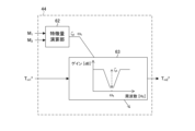
- FIG. 8 is a block diagram showing the configuration of the natural vibration suppressing section 44 (see FIG. 5). As shown in FIG. 8 , the natural vibration suppressing section 44 includes a feature quantity computing section 62 and a first damping correction processing section 63 .
- Feature amount calculation unit 62 specifies the dynamic characteristics of connection portion 101 to which connection vehicle 102 is connected by calculating the characteristic amount of longitudinal vibration caused by connection portion 101 to which connection vehicle 102 is connected. Specifically, the feature quantity calculation unit 62 calculates the natural vibration frequency ⁇ t and the damping coefficient ⁇ t , which are the feature quantity of the longitudinal vibration, based on the electric vehicle weight M 1 and the coupled vehicle weight M 2 according to the above-described equations (18) and (19). As shown in equations (18) and (19), the viscous characteristic C F and the elastic characteristic K F of the connecting portion 101 are used to calculate the natural vibration frequency ⁇ t and the damping coefficient ⁇ t of the longitudinal vibration.
- the connecting portion 101 is, for example, a genuine part of the electric vehicle 100 .
- the viscous characteristic C F and the elastic characteristic K F are known due to the design of the connecting portion 101 .
- the natural vibration frequency ⁇ t and the damping coefficient ⁇ t of the longitudinal vibration are input to the first damping correction processing section 63 .
- the first damping correction processing unit 63 calculates a second torque target value T m2 * by correcting the first torque target value T m1 * based on the natural vibration frequency ⁇ t of the longitudinal vibration and the damping coefficient ⁇ t .
- the correction processing performed by the first damping correction processing section 63 is the first damping correction processing for reducing or removing the longitudinal vibration component.
- the first damping correction processing unit 63 is configured by, for example, a band-stop filter whose frequency band (center frequency) for reducing the signal and gain in the frequency band are variable.
- the first damping correction processing section 63 sets the frequency band (center frequency) of this band-stop filter according to the natural vibration frequency ⁇ t of the longitudinal vibration.
- the center frequency is set to the natural vibration frequency ⁇ t of the back-and-forth vibration.
- the first damping correction processing section 63 sets the gain at the center frequency of this band-stop filter according to the damping coefficient ⁇ t of the longitudinal vibration. In this embodiment, as shown in FIG.
- the gain for the center frequency (the natural vibration frequency ⁇ t of the longitudinal vibration) is set smaller as the damping coefficient ⁇ t of the longitudinal vibration is smaller. That is, the smaller the damping coefficient ⁇ t and the more difficult it is to dampen the longitudinal vibration, the larger the drop in the gain at the center frequency ⁇ t . As a result, the back-and-forth vibration is efficiently suppressed.
- the first damping correction processing section 63 is configured by, for example, a notch filter that is one form of a bandstop filter.
- the transfer characteristic of the notch filter is represented by Equation (20) below.
- equation (20) " ⁇ " is the center frequency and " ⁇ ” is the damping factor.
- "D” is a parameter (hereinafter simply referred to as "gain D") that determines the depth of gain drop at the center frequency. Therefore, the first damping correction processing section 63 sets the center frequency ⁇ of the notch filter to the natural vibration frequency ⁇ t of the longitudinal vibration. Further, the first damping correction processing section 63 sets the gain D of the notch filter according to the damping coefficient ⁇ t of the longitudinal vibration.
- the attenuation coefficient ⁇ of the notch filter is related to the width of the frequency band in which the gain is reduced.
- the attenuation coefficient ⁇ of the notch filter is determined in advance based on experiments, simulations, or the like, and is preferably set to a value of at least 1 or more.
- the setting is the same as that of the notch filter.
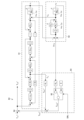
- FIG. 9 is a block diagram showing the configuration of the power transmission mechanism vibration suppressing section 37 (see FIG. 2).
- the power transmission mechanism vibration suppressor 37 includes a feedforward compensator 64 , a feedback compensator 65 , and an adder 66 .
- Feedforward compensator 64 uses transmission characteristic G p (s), which is a vehicle model of electric vehicle 100, to compensate in advance for power transmission mechanism vibration caused by transmission of motor torque T m corresponding to third torque target value T m3 * to driving wheels 23 by the power transmission mechanism. That is, the feedforward compensator 64 calculates the fourth target torque value Tm4 * by compensating for the power transmission mechanism vibration component included in the third target torque value Tm3 * .
- the feedforward compensator 64 is represented by a transfer characteristic G r (s ) /G p (s) composed of a vehicle model transfer characteristic G p (s) and a reference response transfer characteristic G r (s).
- a fourth torque target value T m4 * which is the torque target value after feedforward compensation, is input to the adder 66 .
- the feedback compensator 65 compensates for vibration of the power transmission mechanism caused by disturbances such as road gradients based on the sixth torque target value T m6 * (previous value), which eventually becomes the torque command value, and the actual motor rotation speed ⁇ m .
- the feedback compensator 65 includes a motor rotation speed estimator 71 , a deviation calculator 72 , a disturbance estimator 73 , and a gain multiplier 74 .
- Motor rotation speed estimating unit 71 uses transfer characteristic G p (s), which is a vehicle model of electric vehicle 100, to calculate motor rotation speed estimated value ⁇ m ⁇ that is an estimated value of motor rotation speed ⁇ m from sixth torque target value T m6 * .
- the deviation calculator 72 calculates a deviation (hereinafter referred to as a motor rotation speed deviation ⁇ m ) between the detected value of the motor rotation speed ⁇ m and the motor rotation speed estimated value ⁇ m ⁇ .
- the motor rotation speed deviation ⁇ m is calculated by subtracting the motor rotation speed ⁇ m from the motor rotation speed estimated value ⁇ m ⁇ .
- a disturbance estimator 73 calculates an estimated disturbance value d ⁇ based on the motor rotation speed deviation ⁇ m .
- the estimated disturbance value d ⁇ is an estimated value of a disturbance such as a road surface gradient.
- the disturbance estimator 73 is represented by, for example, the transfer characteristic H 2 (s)/G p (s).
- the transfer characteristic H 2 (s) is set such that the difference between the denominator order and the numerator order is greater than or equal to the difference between the denominator order and the numerator order of the transfer characteristic G p (s).
- the estimated disturbance value d ⁇ is input to the gain multiplier 74 .
- the gain multiplier 74 multiplies the estimated disturbance value d ⁇ by the feedback gain KFB to calculate the fifth torque target value Tm5 * .
- the feedback gain K FB is determined in advance by, for example, experiments or simulations.
- the fifth torque target value T m5 * represents the torque associated with the power transmission mechanism vibration caused by the disturbance, that is, the amount of compensation corresponding to the disturbance for the motor torque T m .
- the fifth torque target value T m5 * is input to the adder 66 .
- the adder 66 calculates a sixth target torque value Tm6* by adding the fourth target torque value Tm4 * , which is the target torque value after feedforward compensation, and the fifth target torque value Tm5 * , which is feedback torque.
- the sixth torque target value T m6 * is the final command value for the motor torque T m as described above.
- the second damping correction process performed by the power transmission mechanism vibration suppression unit 37 is composed of compensation processing by the feedforward compensation unit 64 and compensation processing by the feedback compensation unit 65 .
- FIG. 10 is a graph showing the transfer characteristic H 2 (s) used in the disturbance estimator 73.
- the transfer characteristic H 2 (s) is, for example, a bandpass filter.
- the feedback compensator 65 serves as a feedback element that selectively reduces vibration components due to disturbance.
- the transfer characteristic H 2 (s) is configured, for example, so that the damping coefficient on the low-pass side and the damping coefficient on the high-pass side are approximately the same.
- the transmission characteristic H 2 (s) is set such that the center frequency f p of its passband substantially coincides with the torsional resonance frequency ⁇ p of the power transmission mechanism (especially the drive shaft 22).
- the horizontal axis (frequency) in FIG. 10 is a logarithmic scale.
- the transfer characteristic H 2 (s) is composed of a first-order high-pass filter and a first-order low-pass filter
- Equation (21) the transfer characteristic H 2 (s) is represented by Equation (21) below.
- ⁇ H and ⁇ L are the time constant of the high-pass filter and the time constant of the low-pass filter, respectively.
- ⁇ L 1/(2 ⁇ f HC )
- f HC k ⁇ f p
- ⁇ H 1/(2 ⁇ f LC )
- f LC f p /k. Note that “k” is an arbitrary constant, and “f HC ” and “f LC ” are cutoff frequencies on the high frequency side and the low frequency side, respectively.
- FIG. 11 is a block diagram showing the configuration of the current control processing section 35 (see FIG. 2). As shown in FIG. 11 , the current control processing section 35 includes a voltage command value calculation section 81 , a coordinate conversion section 82 , a PWM conversion section 83 and a coordinate conversion section 84 .
- the voltage command value calculation unit 81 calculates smoothed non-interference voltages V d-dcpl-flt * and V q- dcpl-flt * by processing the non-interference voltages V d-dcpl * and V q-dcpl * with a low-pass filter.
- the voltage command value calculation unit 81 calculates the d-axis voltage command value V d * and the q-axis voltage command value V q * (hereinafter referred to as the dq-axis voltage command value V d * , V q * ) .
- the dq-axis currents i d and i q are calculated by the coordinate conversion section 84 .
- the coordinate conversion unit 82 converts the dq-axis voltage command values V d * and V q * into voltage command values for each of the UVW phases (hereinafter referred to as three-phase voltage command values V u * , V v * and V w * ) based on the rotor phase ⁇ of the motor 10 according to the following equation (22).
- PWM converter 83 generates PWM signals D uu * , D ul * , D vu * , D vl *, D wu * , D wl * , which are drive signals for switching elements of inverter 12, according to three-phase voltage command values V u * , V v * , V w * .
- the motor 10 is controlled to output the motor torque Tm according to the sixth torque target value Tm6 * .
- a coordinate conversion unit 84 calculates a W-phase current iw based on the U-phase current iu and the V-phase current iv detected by the current sensor 24 . Then, the coordinate conversion unit 84 converts these currents i u , iv and i w into dq axis currents id and iq using the rotor phase ⁇ of the motor 10 according to the following equation (23). The dq-axis currents i d and i q are used in the voltage command value calculator 81 as described above.
- the input processing unit 31 includes a motor rotation speed calculation unit 85 .
- a motor rotation speed calculator 85 calculates a motor rotation speed ⁇ m based on the rotor phase ⁇ of the motor 10 .
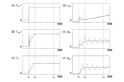
- FIG. 12 is a time chart showing the longitudinal acceleration AL1 and the like during towing.
- FIG. 12A is a time chart of the first torque target value T m1 * .
- FIG. 12B is a time chart of the sixth torque target value T m6 * .
- FIG. 12(C) is a time chart of the drive shaft torque Td .
- FIG. 12D is a time chart of the motor rotation speed ⁇ m .
- FIG. 12(E) is a time chart showing the longitudinal acceleration AL1 of the electric vehicle 100.
- FIG. FIG. 12F is a time chart showing the longitudinal acceleration AL2 of the articulated vehicle 102.
- FIG. 12A is a time chart of the first torque target value T m1 * .
- FIG. 12B is a time chart of the sixth torque target value T m6 * .
- FIG. 12(C) is a time chart of the drive shaft torque Td .
- FIG. 12D is a time chart of the motor rotation speed ⁇ m
- the solid lines show an example when the damping control according to the present embodiment is performed
- the dashed lines show an example when the damping control according to the comparative example is performed.
- the comparative example is an example in which the damping control section 33 does not perform the first damping correction processing by the longitudinal vibration suppressing section 36 .
- the first torque target value T m1 * is input in steps at time t 1 by the driver's accelerator operation.
- the sixth torque target value Tm6 * increases to a predetermined torque corresponding to the demand (accelerator opening Apo ) by accelerator operation.
- the drive shaft torque T d changes following the sixth torque target value T m6 * .
- the power transmission mechanism vibration is compensated for by the second damping correction process, so the change in the drive shaft torque Td is smooth.
- the motor rotation speed ⁇ m changes according to changes in the sixth torque target value T m6 * .
- This back-and-forth vibration continues after time t2 when the sixth torque target value Tm6 * converges to torque corresponding to the accelerator opening Apo .
- this back-and-forth oscillation continues even at time t3 after a sufficient amount of time has passed since the sixth torque target value Tm6 * converged.
- the first damping correction process is performed, so the longitudinal vibration between the electrically powered vehicle 100 and the coupled vehicle 102 is suppressed.
- FIG. 13 is a time chart showing the longitudinal acceleration AL1 and the like when the combined vehicle 102 is heavy. 13 shows a case in which the weight M2 of the articulated vehicle 102 is larger than in the case of FIG.
- the parameters shown in FIGS. 13A to 13F and the distinction between solid and broken lines are the same as in FIG.
- the weight M2 of the vehicle 102 is increased, so that the longitudinal vibrations of the electric vehicle 100 and the vehicle 102 are appropriately suppressed despite the change in the dynamic characteristics as described above.
- the first torque target value T m1 * is corrected by the first damping correction process to calculate the sixth torque target value T m6 * , which is the final torque command value, and the motor 10 is controlled according to this sixth torque target value T m6 * .
- the front-rear vibration that is peculiar to towing is suppressed.
- the effect of suppressing this longitudinal vibration can be obtained regardless of the size of the weight M2 of the towed vehicle 102 or the like.
- the torque rise and smooth acceleration required by the vehicle operation can be achieved regardless of the weight M2 of the coupled vehicle 102.
- the damping control unit 33 is composed of the longitudinal vibration suppressing unit 36 and the power transmission mechanism vibration suppressing unit 37, and the compensation of the longitudinal vibration peculiar to towing and the compensation of the power transmission mechanism vibration are performed separately, respectively, but the present invention is not limited to this.
- the damping control section 33 may be configured to substantially integrally perform compensation for longitudinal vibrations unique to towing and compensation for power transmission mechanism vibrations.
- a second embodiment in which the longitudinal vibration suppressing section 36 and the feedforward compensating section 64 (see FIG. 9) that is part of the power transmission mechanism vibration suppressing section 37 are integrally configured will be described below.
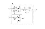
- FIG. 14 is a block diagram showing a partial configuration of the damping control section 33 in the second embodiment.
- the damping control section 33 of the second embodiment does not explicitly have the longitudinal vibration suppressing section 36 of the first embodiment. Therefore, in the damping control section 33 of the second embodiment, the feedforward compensation section 64 is configured to directly calculate the fourth target torque value Tm4 * based on the first target torque value Tm1 * .
- the feedforward compensation unit 64 of the second embodiment includes a vehicle model of the electric vehicle 100 (hereinafter referred to as an electric vehicle model 91), a model of the connected vehicle 102 connected to the connection unit 101 (hereinafter referred to as a connected vehicle model 92), a compensation torque calculation unit 93, and a damping correction processing unit 94.
- the electric vehicle model 91 calculates an estimated value of the motor torque Tm corresponding to the fourth target torque value Tm4 * (hereinafter simply referred to as torque estimated value Tm ⁇ ) based on the fourth target torque value Tm4 * (previous value) that is the output of the feedforward compensator 64.
- the electric vehicle model 91 is basically configured according to Equations (2) to (7), which are equations of motion of the electric vehicle 100 .
- the electric vehicle model 91 is configured to calculate the vehicle body speed v1 of the electric vehicle 100 using the force f12 acting between the electric vehicle 100 and the connected vehicle 102 based on equations (8) to (11). In this embodiment, the force f 12 is calculated in the articulated vehicle model 92 .
- the weight M1 of the electric vehicle 100 used in the process of calculating the vehicle body speed v1 of the electric vehicle 100 is calculated by a configuration similar to that of the electric vehicle weight calculator 42 of the first embodiment. That is, the weight M1 of the electric vehicle 100 used in the electric vehicle model 91 is a variable parameter.
- the estimated torque value T m ⁇ is input to the compensation torque calculator 93 .
- Vehicle speed v 1 is input to articulated vehicle model 92 .
- Articulated vehicle model 92 is configured to calculate vehicle body speed v2 of articulated vehicle 102 according to equations (8)-(11). Specifically, the vehicle speed v2 of the coupled vehicle 102 is calculated based on the deviation between the vehicle speed v1 of the electrically powered vehicle 100 and the vehicle speed v2 of the coupled vehicle 102, that is, the relative vehicle speed ⁇ v12 between the electrically powered vehicle 100 and the coupled vehicle 102. In calculating the relative vehicle speed ⁇ v12 , the vehicle speed v1 of the electric vehicle 100 is obtained from the electric vehicle model 91, and the previous value calculated by the connected vehicle model 92 is used as the vehicle speed v2 of the connected vehicle 102.
- the viscous characteristic CF and the elastic characteristic KF which are the mechanical characteristics of the connecting portion 101, are used to calculate the vehicle body speed v2 of the connected vehicle 102.
- FIG. Therefore, the dynamic characteristics of the connection portion 101 to which the articulated vehicle 102 is connected are substantially reflected in the value of the vehicle body speed v2 of the articulated vehicle 102 .
- the weight M2 of the articulated vehicle 102 used in the process of calculating the vehicle body speed v2 of the articulated vehicle 102 is calculated by the same configuration as the electric vehicle weight calculation unit 42, the gross weight calculation unit 41, and the connection vehicle weight calculation unit 43 of the first embodiment. That is, the weight M2 of articulated vehicle 102 used in articulated vehicle model 92 is a variable parameter.
- the force f 12 calculated in the process of calculating the vehicle speed v 2 is input to the electric vehicle model 91 .
- the relative vehicle speed ⁇ v 12 is input to the compensation torque calculator 93 .
- the relative vehicle speed ⁇ v12 substantially reflects the dynamic characteristics of the connection portion 101 to which the articulated vehicle 102 is connected via the vehicle body speed v2 of the articulated vehicle 102 .
- the compensating torque calculator 93 calculates a first compensating torque T FF1 * by multiplying the estimated torque value T m ⁇ by a predetermined gain K 1 that is determined in advance through experiments, simulations, or the like.
- the first compensating torque T FF1 * precompensates for the torque corresponding to the power transmission mechanism vibration.
- the compensating torque calculator 93 calculates a second compensating torque T FF2 * based on the relative vehicle speed ⁇ v12 .
- the second compensating torque T FF2 * preliminarily compensates for the torque corresponding to the longitudinal vibration caused by the connection of the connected vehicle 102 to the connecting portion 101 . More specifically, when the coupled vehicle 102 is coupled to the coupling portion 101, the compensating torque calculating portion 93 multiplies the relative vehicle speed ⁇ v 12 by a predetermined gain K2 determined in advance by experiments, simulations, or the like, and sets the value as the second compensating torque T FF2 * . On the other hand, when the connected vehicle 102 is not connected to the connection portion 101, the compensation torque calculation portion 93 sets the fixed value zero (“0”) as the second compensation torque T FF2 * .
- the switching of the second compensating torque T FF2 * is performed by the second compensating torque switching unit 95 based on the traction travel signal SW T. That is, when the second compensating torque switching unit 95 determines that the coupled vehicle 102 is coupled to the coupling unit 101 based on the traction travel signal SWT , the second compensating torque T FF2 * becomes a value based on the relative vehicle speed ⁇ v 12 . On the other hand, when the second compensating torque switching unit 95 determines that the coupled vehicle 102 is coupled to the coupling unit 101 based on the traction travel signal SWT , the second compensating torque T FF2 * is zero.
- the compensating torque calculator 93 calculates the third compensating torque TFF3 * by adding the first compensating torque TFF1 * and the second compensating torque TFF2 * calculated as described above. Therefore, the third compensating torque T FF3 * is, in principle, a torque for precompensating for the vibration of the power transmission mechanism, but when the connecting vehicle 102 is connected to the connecting portion 101, it further includes a torque for precompensating for the longitudinal vibration peculiar to towing.
- the third compensating torque T FF3 * is input to the damping correction processing section 94 .
- the damping correction processing unit 94 calculates a fourth target torque value Tm4 * by correcting the first target torque value Tm1 * using the third compensating torque TFF3 * . Then, when the articulated vehicle 102 is connected to the connecting portion 101, the correction processing performed by the damping correction processing portion 94 is substantially correction processing including the first damping correction processing and feedforward compensation of the first embodiment. Therefore, the fourth torque target value T m4 * calculated by the damping correction processing section 94 is substantially the same value as the fourth torque target value T m4 * output by the feedforward compensation section 64 of the first embodiment. Therefore, the fourth torque target value T m4 * becomes the sixth torque target value T m6 * by the feedback compensator 65 and the adder 66 as in the first embodiment, and is used as the final torque command value.
- the longitudinal vibration suppressing section 36 and the feedforward compensating section 64 of the first embodiment can be configured integrally.
- the fourth torque target value T m4 * output by the feedforward compensator 64 of the second embodiment, which integrates these components, is substantially the same as the fourth torque target value T m4 * of the first embodiment. Therefore, even when the longitudinal vibration suppressor 36 and the feedforward compensator 64 of the first embodiment are integrated as described above, the same functions and effects as those of the first embodiment can be obtained (see FIGS. 12 and 13).
- the feedforward compensator 64 of the second embodiment substantially performs damping control based on the transmission characteristics from the input of the first target torque value T m1 * to the output of the fourth target torque value T m4 * .
- the electric vehicle weight M1 and the connected vehicle weight M2 that constitute this transmission characteristic are variable parameters. Therefore, the control according to the second embodiment changes (adjusts) the contents of the transmission characteristics depending on whether or not the vehicle 102 is connected to the connecting portion 101, thereby suppressing the longitudinal vibrations peculiar to towing.
- modeling errors such as the transfer characteristic G p (s) may not be negligible. In such a situation, even if the correction process for suppressing the longitudinal vibration of the first embodiment or the second embodiment is performed, the longitudinal vibration may still occur.
- the third embodiment a configuration capable of suitably suppressing back-and-forth vibration without depending on errors included in known values of the elastic characteristic KF and viscous characteristic CF of the connecting portion 101 or on modeling errors will be described.
- FIG. 15 is a block diagram showing the configuration of the longitudinal vibration suppression section 36 in the third embodiment.
- the longitudinal acceleration AL1 is input to the natural vibration suppressing portion 44 of the longitudinal vibration suppressing portion 36 of the third embodiment.
- the natural vibration suppression unit 44 uses the electric vehicle weight M 1 , the coupled vehicle weight M 2 , the viscous characteristic C F and the elastic characteristic K F that are the mechanical characteristics of the coupling unit 101, and the longitudinal acceleration AL1 to perform the first damping correction process on the first torque target value T m1 * .
- the longitudinal acceleration AL1 is configured in the same manner as the longitudinal vibration suppressing portion 36 of the first embodiment.
- FIG. 16 is a block diagram showing the configuration of the natural vibration suppressing section 44 in the third embodiment.
- the natural vibration suppression unit 44 of the third embodiment includes a change rate calculation unit 301, a reference response calculation unit 302, a difference calculation unit 303, a feature amount calculation unit 304, a dynamic characteristic setting unit 305, and a first vibration suppression correction processing unit 306.
- the change rate calculator 301 calculates the rate of change of the motor torque Tm or a parameter corresponding to the rate of change of the motor torque Tm . Thereby, change rate calculation unit 301 determines a driving scene in which longitudinal vibration is likely to occur.
- the change rate calculation unit 301 calculates the amount of change in the first torque target value T m1 * in a predetermined time (for example, one control cycle), that is, the time change rate of the first torque target value T m1 * (hereinafter simply referred to as the change rate ⁇ T m1 * of the first torque target value T m1 * ). More specifically, the change rate calculator 301 holds the previous value T m1z * (not shown) of the first torque target value T m1 * .
- the change rate calculation unit 301 compares the current value and the previous value T m1z * of the first torque target value T m1 * , or calculates the difference between the current value and the previous value T m1z * of the first torque target value T m1 * , thereby calculating the rate of change ⁇ T m1 * of the first torque target value T m1 * .
- the change rate ⁇ T m1 * of the first torque target value T m1 * is a parameter that substantially represents the change rate (time change rate) of the motor torque T m .
- change rate calculation section 301 determines a driving scene in which longitudinal vibration is likely to occur based on change rate ⁇ T m1 * of first torque target value T m1 * . Specifically, the greater the rate of change ⁇ T m1 * of the first torque target value T m1 * , the more likely the longitudinal vibration will occur. Further, when the rate of change ⁇ T m1 * of the first torque target value T m1 * is large, if there is an error in the elastic characteristic KF or the viscous characteristic CF , or if there is a modeling error, the longitudinal vibration tends to remain even if the correction processing for suppressing the longitudinal vibration of the first embodiment or the second embodiment is performed.
- the change rate calculator 301 compares the change rate ⁇ T m1 * of the first torque target value T m1 * with the change rate threshold ⁇ T TH , and determines a driving scene in which the possibility of occurrence of longitudinal vibration is high when the change rate ⁇ T m1 * of the first torque target value T m1 * is greater than the change rate threshold ⁇ T TH .
- the change rate threshold ⁇ T TH is set in advance based on experiments, simulations, or the like with respect to the change rate ⁇ T m1 * of the first torque target value T m1 * .
- Change rate calculation unit 301 sets a dynamic characteristic calculation flag FLG according to the comparison result between change rate ⁇ T m1 * of first torque target value T m1 * and change rate threshold ⁇ T TH .
- the dynamic characteristic calculation flag FLG is an index that instructs to newly calculate the natural vibration frequency ⁇ t and the damping coefficient ⁇ t (specify the dynamic characteristic of the connecting portion 101) based on the longitudinal acceleration AL1 and the like.
- the dynamic characteristic calculation flag FLG is set to, for example, "1" or "0". When the flag FLG is "1", the natural vibration frequency ⁇ t and the damping coefficient ⁇ t are calculated based on the longitudinal acceleration AL1 and the like.
- Change rate calculation unit 301 sets dynamic characteristic calculation flag FLG to "1" when change rate ⁇ Tm1 * of first torque target value Tm1 * is greater than change rate threshold value ⁇ TTH .
- change rate calculation unit 301 sets dynamic characteristic calculation flag FLG to "0" when change rate ⁇ T m1 * of first torque target value T m1 * is equal to or less than change rate threshold value ⁇ T TH .
- Change rate calculation unit 301 inputs dynamic characteristic calculation flag FLG to, for example, reference response calculation unit 302 and the like.
- the reference response calculation unit 302 calculates a reference response A L1-ref of the longitudinal acceleration A L1 at least in a driving scene in which longitudinal vibration is highly likely to occur. In this embodiment, reference response calculation unit 302 calculates reference response A L1-ref of longitudinal acceleration A L1 when dynamic characteristic calculation flag FLG is "1".
- Reference response calculation unit 302 calculates reference response A L1-ref of longitudinal acceleration A L1 based on electric vehicle weight M 1 , coupled vehicle weight M 2 , and first torque target value T m1 * . Specifically, the reference response calculation unit 302 applies the reference transmission characteristic G pF-ref (s) represented by the following expression (24) to the first torque target value T m1 * , thereby calculating the reference response A L1-ref of the longitudinal acceleration A L1 according to the following expression (25). The reference response A L1 -ref of the longitudinal acceleration A L1 is input to the difference calculation section 303 .
- the reference transmission characteristic G pF-ref (s) represents a reference response from the motor torque T m to the driving force F.
- the reference response A L1-ref of the longitudinal acceleration A L1 is calculated in the same manner as the estimated longitudinal acceleration A L1 ⁇ , so the reference response A L1 -ref of the longitudinal acceleration A L1 is an estimated value.
- the above calculation method for the reference response A L1 -ref of the longitudinal acceleration A L1 is an example, and the reference response A L1-ref of the longitudinal acceleration A L1 can be calculated using, for example, the vehicle model represented by the above equation (19).
- a difference calculation unit 303 calculates a difference ⁇ A L1 between the longitudinal acceleration A L1 , which is the actual response, and the reference response A L1-ref .
- the difference calculator 303 calculates the difference ⁇ A L1 by subtracting the reference response A L1-ref from the longitudinal acceleration A L1 , which is the actual response. Further, difference calculation unit 303 continuously calculates difference ⁇ AL1 at least for a predetermined period PP after dynamic characteristic calculation flag FLG becomes “1”. That is, the difference ⁇ A L1 constitutes a data string that can change over time.
- the difference ⁇ AL1 calculated by the difference calculator 303 is input to the feature quantity calculator 304 .
- the “predetermined period PP” in which the difference ⁇ A L1 is calculated is a time interval at which time-series data of the difference ⁇ A L1 can be acquired to the extent that frequency analysis can be performed.
- the difference calculation unit 303 can perform filtering processing for extracting components in the specified frequency range from the output difference ⁇ A L1 . In this case, noise superimposed on the difference ⁇ AL1 (for example, noise caused by disturbance or the like) is removed, so that the longitudinal vibration suppression accuracy is improved.
- Feature amount calculation unit 304 identifies the dynamic characteristics of connection portion 101 to which connection vehicle 102 is connected by calculating a feature amount of longitudinal vibration caused by connection of connection vehicle 102 to connection portion 101 .
- the feature amount calculation unit 304 calculates the characteristic amount of longitudinal vibration, the natural vibration frequency ⁇ t and the damping coefficient ⁇ t , based on the difference ⁇ A L1 between the longitudinal acceleration A L1 , which is the actual response, and the reference response A L1-ref . That is, the feature amount calculation unit 304 holds the difference ⁇ A L1 for the predetermined period PP, and calculates the natural vibration frequency ⁇ t and the damping coefficient ⁇ t based on the time-series data.
- the feature amount calculation unit 304 can calculate the natural vibration frequency ⁇ t and the damping coefficient ⁇ t by subjecting the time-series data of the difference ⁇ A L1 to frequency analysis such as FFT (Fast Fourier Transform). In this embodiment, the feature amount calculator 304 simply calculates the natural vibration frequency ⁇ t and the damping coefficient ⁇ t based on the number of peaks (or bottoms) formed by the difference ⁇ A L1 of the predetermined period PP and the change in amplitude.
- FFT Fast Fourier Transform
- the characteristic amount calculator 304 does not use the viscous characteristic C F and the elastic characteristic K F of the connecting portion 101 to calculate the natural vibration frequency ⁇ t and the damping coefficient ⁇ t . That is, the feature quantity calculation unit 304 specifies the dynamic characteristics of the connecting part 101 by calculating the natural vibration frequency ⁇ t and the damping coefficient ⁇ t , which are the feature quantities of the longitudinal vibration, using a method different from that of the feature quantity calculation unit 62 of the first embodiment. The natural vibration frequency ⁇ t and the damping coefficient ⁇ t calculated by the feature amount calculation unit 304 are input to the dynamic characteristic setting unit 305 .
- the feature amount calculation unit 304 compares the difference ⁇ A L1 with the acceleration threshold ⁇ A TH . Then, when the difference ⁇ A L1 is greater than the acceleration threshold ⁇ A TH , the feature amount calculation unit 304 holds the time-series data of the difference ⁇ A L1 , and calculates the natural vibration frequency ⁇ t and the damping coefficient ⁇ t based on the time-series data of the difference ⁇ A L1 .
- the feature amount calculation unit 304 calculates a new natural vibration frequency ⁇ t and damping coefficient ⁇ t based on the time-series data of the difference ⁇ A L1 .
- the feature amount calculation unit 304 determines that even if longitudinal vibration occurs, the scene can be substantially ignored.
- the feature amount calculation unit 304 sets (resets) the dynamic characteristic calculation flag FLG to "0" and does not calculate a new natural vibration frequency ⁇ t and damping coefficient ⁇ t based on the difference ⁇ A L1 .
- the acceleration threshold ⁇ A TH is determined in advance by experiments, simulations, or the like.
- the dynamic characteristic setting unit 305 sets the natural vibration frequency ⁇ t and the damping coefficient ⁇ t to be finally used as the dynamic characteristic of the coupling unit 101 to the first damping correction processing unit 306 .
- an initial value ⁇ t0 (not shown) of the natural vibration frequency ⁇ t and an initial value ⁇ t0 (not shown) of the damping coefficient ⁇ t are predetermined. Therefore, when the dynamic characteristic calculation flag FLG does not become “1” and the feature amount calculation unit 304 does not newly calculate the natural vibration frequency ⁇ t and the damping coefficient ⁇ t , the dynamic characteristic setting unit 305 sets the initial values ⁇ t0 and ⁇ t0 to the natural vibration frequency ⁇ t and the damping coefficient ⁇ t that are finally used as the dynamic characteristics of the coupling unit 101.
- the initial values ⁇ t0 and ⁇ t0 are set based on, for example, the viscous characteristic C F and elastic characteristic K F of the connecting portion 101, the vehicle model of the electric vehicle 100, and the like.
- the dynamic characteristic setting unit 305 compares the newly calculated natural vibration frequency ⁇ t and the damping coefficient ⁇ t with the existing constants.
- the existing constants are the natural vibration frequency ⁇ t and the damping coefficient ⁇ t already used as the dynamic characteristics of the connecting portion 101, for example, their previous values ⁇ tz and ⁇ tz (not shown).
- the previous values ⁇ tz and ⁇ tz of the natural vibration frequency ⁇ t and the damping coefficient ⁇ t are, for example, their initial values ⁇ t0 and ⁇ t0 .
- the dynamic characteristic setting unit 305 calculates the frequency deviation ⁇ t , which is the deviation between the natural vibration frequency ⁇ t newly calculated by the feature amount calculation unit 304 and the previous value ⁇ tz of the natural vibration frequency ⁇ t , and compares it with the frequency threshold ⁇ TH .
- the frequency threshold ⁇ TH is determined in advance by experiment, simulation, or the like. Then, when the frequency deviation ⁇ t is greater than the frequency threshold ⁇ TH , the dynamic characteristic setting unit 305 updates the natural vibration frequency ⁇ t used as the dynamic characteristic of the connecting unit 101 to the natural vibration frequency ⁇ t newly calculated by the feature amount calculation unit 304 .
- the dynamic characteristic setting unit 305 maintains the natural vibration frequency ⁇ t used as the dynamic characteristic of the connecting unit 101 at the previous value ⁇ tz . That is, the dynamic characteristic setting unit 305 updates the natural vibration frequency ⁇ t when the natural vibration frequency ⁇ t deviates from the existing constant by a predetermined amount or more.
- the dynamic characteristic setting unit 305 calculates the damping coefficient deviation ⁇ t , which is the difference between the damping coefficient ⁇ t newly calculated by the feature quantity calculating unit 304 and the previous value ⁇ tz of the damping coefficient ⁇ t , and compares it with the damping coefficient threshold ⁇ TH .
- the damping coefficient threshold ⁇ TH is determined in advance through experiments, simulations, or the like. Then, when the damping coefficient deviation ⁇ t is greater than the damping coefficient threshold ⁇ TH , the dynamic characteristic setting unit 305 updates the damping coefficient ⁇ t used as the dynamic characteristic of the connecting unit 101 to the damping coefficient ⁇ t newly calculated by the feature amount calculating unit 304 .
- the dynamic characteristic setting unit 305 maintains the damping coefficient ⁇ t used as the dynamic characteristic of the coupling unit 101 at the previous value ⁇ tz . That is, the dynamic characteristic setting unit 305 updates the damping coefficient ⁇ t when the damping coefficient ⁇ t deviates from the existing constant by a predetermined degree or more. Note that the natural vibration frequency ⁇ t and the damping coefficient ⁇ t can be updated or maintained independently of each other.
- the dynamic characteristic setting unit 305 limits the range of the natural vibration frequency ⁇ t that can be set. Specifically, the dynamic characteristic setting unit 305 defines an upper limit and a lower limit for the natural vibration frequency ⁇ t , and updates or maintains the natural vibration frequency ⁇ t within the range of the upper limit and the lower limit.
- the upper and lower limits of the natural vibration frequency ⁇ t define the range of the natural vibration frequency ⁇ t that can be realistically obtained during towing, and are determined in advance by experiments, simulations, or the like.
- dynamic characteristic setting section 305 limits the range of damping coefficient ⁇ t that can be set.
- the dynamic characteristic setting unit 305 defines an upper limit and a lower limit for the damping coefficient ⁇ t , and updates or maintains the damping coefficient ⁇ t within the range of the upper limit and the lower limit.
- the upper and lower limits of the damping coefficient ⁇ t define the range of the damping coefficient ⁇ t that can be realistically obtained during towing, and are determined in advance by experiments, simulations, or the like.
- the dynamic characteristic setting unit 305 limits the ranges of the natural vibration frequency ⁇ t and the damping coefficient ⁇ t that can be set to realistic ranges. As a result, even if there is an estimation error in the natural vibration frequency ⁇ t and the damping coefficient ⁇ t in the feature amount calculation unit 304, the behavior of the electric vehicle 100 will not become unexpectedly unstable due to the estimation error.
- the first damping correction processing section 306 is configured in the same manner as the first damping correction processing section 63 (see FIG. 8) of the first embodiment, except that the natural vibration frequency ⁇ t and the damping coefficient ⁇ t are set by the dynamic characteristic setting section 305 . That is, the first damping correction processing section 306 calculates the second torque target value T m2 * by correcting the first torque target value T m1 * based on the natural vibration frequency ⁇ t and the damping coefficient ⁇ t set by the dynamic characteristic setting section 305 .
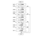
- FIG. 17 is a flowchart for updating the natural vibration frequency and the like.
- the change rate calculator 301 calculates the change rate ⁇ T m1 * of the first torque target value T m1 *.
- change rate calculation unit 301 compares change rate ⁇ T m1 * of first torque target value T m1 * with change rate threshold ⁇ T TH to set dynamic characteristic calculation flag FLG.
- step S302 when the change rate ⁇ T m1 * of the first torque target value T m1 * is greater than the change rate threshold ⁇ T TH , the dynamic characteristic calculation flag FLG is set to "1", and the process proceeds to step S303.
- This is a driving scene in which there is a high possibility that longitudinal vibration will occur during towing.
- the change rate ⁇ T m1 * of the first torque target value T m1 * is equal to or less than the change rate threshold ⁇ T TH in step S302
- the natural vibration frequency ⁇ t and the damping coefficient ⁇ t are maintained at the previous values ⁇ tz and ⁇ tz , and the updating process shown in this flowchart ends.
- This is a driving scene in which longitudinal vibration is less likely to occur during towing.
- step S303 the reference response calculation unit 302 calculates a reference response A L1-ref of the longitudinal acceleration A L1 based on the electric vehicle weight M 1 , the coupled vehicle weight M 2 , and the first torque target value T m1 * .
- step S304 the difference calculation unit 303 calculates the difference ⁇ A L1 between the longitudinal acceleration A L1 , which is the actual response, and the reference response A L1-ref .
- step S305 the feature quantity calculation unit 304 compares the difference ⁇ A L1 with the acceleration threshold ⁇ A TH to determine whether or not significant longitudinal vibration occurs.
- step S305 when the difference ⁇ A L1 is equal to or less than the acceleration threshold ⁇ A TH and the generated longitudinal vibration is negligible, the natural vibration frequency ⁇ t and the damping coefficient ⁇ t are maintained at the previous values ⁇ tz and ⁇ tz , and the updating process shown in this flowchart ends.
- step S305 when the difference ⁇ A L1 is greater than the acceleration threshold ⁇ A TH in step S305, the process proceeds to step S306, and the feature amount calculation unit 304 holds the difference ⁇ A L1 in the predetermined period PP. Then, in step S307, the feature amount calculation unit 304 calculates a new natural vibration frequency ⁇ t and a new damping coefficient ⁇ t based on the held time-series data of the difference ⁇ A L1 .
- step S308 the dynamic characteristic setting unit 305 calculates the frequency deviation ⁇ t, which is the deviation between the current value of the natural vibration frequency ⁇ t calculated by the feature amount calculation unit 304 and the previous value ⁇ tz of the natural vibration frequency ⁇ t , and compares it with the frequency threshold ⁇ TH . If it is determined in step S308 that the frequency deviation ⁇ t is greater than the frequency threshold value ⁇ TH and that a non-negligible error has occurred in the natural vibration frequency ⁇ t , the process proceeds to step S309, and the dynamic characteristic setting unit 305 updates the natural vibration frequency ⁇ t of the connecting portion 101 to the new natural vibration frequency ⁇ t calculated by the feature amount calculation unit 304.
- step S308 if it is determined in step S308 that the frequency deviation .delta..omega.t is equal to or less than the frequency threshold value .delta..omega.TH and that there is almost no error in the natural vibration frequency .omega.t , step S309 is skipped.
- step S310 the dynamic characteristic setting unit 305 calculates the damping coefficient deviation ⁇ t , which is the deviation between the current value of the damping coefficient ⁇ t calculated by the feature amount calculating unit 304 and the previous value ⁇ tz of the damping coefficient ⁇ t, and compares it with the damping coefficient threshold ⁇ TH .
- step S310 If it is determined in step S310 that the damping coefficient deviation ⁇ t is greater than the damping coefficient threshold ⁇ TH and that a non-negligible error has occurred in the damping coefficient ⁇ t , the process proceeds to step S311, where the dynamic characteristic setting unit 305 updates the damping coefficient ⁇ t of the coupling unit 101 to the new damping coefficient ⁇ t calculated by the feature amount calculation unit 304.
- step S311 is skipped.
- FIG. 18 is a time chart showing the longitudinal acceleration AL1 and the like in a driving scene in which the natural vibration frequency ⁇ t and the like are updated.
- FIG. 18A shows the first torque target value T m1 * .
- FIG. 18(B) shows the second torque target value T m2 * .
- FIG. 18(C) shows the drive shaft torque Td .
- the broken line indicates the dynamic characteristic calculation flag FLG, and the solid line indicates the natural vibration frequency ⁇ t to be counted up.
- FIG. 18(E) shows the motor rotation speed ⁇ m .
- FIG. 18A shows the first torque target value T m1 * .
- FIG. 18(B) shows the second torque target value T m2 * .
- FIG. 18(C) shows the drive shaft torque Td .
- the broken line indicates the dynamic characteristic calculation flag FLG
- the solid line indicates the natural vibration frequency ⁇ t to be counted up.
- FIG. 18(E) shows the motor rotation speed ⁇ m
- FIG. 18F the solid line indicates the longitudinal acceleration A L1 (actual response) of the electric vehicle 100, and the dashed line indicates the reference response A L1-ref of the longitudinal acceleration A L1 .
- FIG. 18G for reference, the solid line indicates the longitudinal acceleration A L2 (actual response) of the articulated vehicle 102, and the dashed line indicates the reference response A L2-ref of the longitudinal acceleration A L2 .
- FIG. 18(H) shows the difference ⁇ A L1 between the longitudinal acceleration A L1 of the electric vehicle 100 and its reference response A L1-ref .
- the horizontal axis of each graph in FIG. 18 is time [s]. Further, time t1 is the start time of the accelerator operation by the driver, and time t2 is the time after the predetermined period PP has elapsed from time t1 .
- the first torque target value Tm1 * is ramp-input according to the amount of operation.
- the dynamic characteristic calculation flag FLG is set to "1".
- the second torque target value T m2 * and the drive shaft torque T d increase following the first torque target value T m1 * .
- the motor rotation speed ⁇ m generally increases with the lapse of time.
- vibration occurs in the longitudinal acceleration AL1 of the electric vehicle 100 .
- the longitudinal acceleration AL2 of the connected vehicle 102 also vibrates in response to the vibration of the longitudinal acceleration AL1 . That is, the electric vehicle 100 and the articulated vehicle 102 vibrate back and forth.
- the vibration of the longitudinal acceleration A L1 has an amplitude that cannot be ignored with respect to the reference response A L1-ref . Therefore, as shown in FIG. Therefore , the feature amount calculation unit 304 holds the time-series data of the difference ⁇ A L1 in the predetermined period PP, and, for example, as shown in FIG.
- the feature quantity calculator 304 obtains the damping coefficient ⁇ t of the longitudinal vibration based on the decrease in the amplitude of the difference ⁇ AL1 .
- the natural vibration frequency ⁇ t and the damping coefficient ⁇ t used as the dynamic characteristics of the connecting unit 101 are updated to the natural vibration frequency ⁇ t and the damping coefficient ⁇ t obtained by the feature amount calculation unit 304 .
- FIG. 19 is a time chart showing the longitudinal acceleration AL1 and the like after updating the natural vibration frequency ⁇ t and the like.
- FIG. 19(A) shows the first torque target value T m1 * .
- FIG. 19B shows the second torque target value T m2 * .
- FIG. 19(C) shows the drive shaft torque Td .
- the broken line indicates the dynamic characteristic calculation flag FLG, and the solid line indicates the natural vibration frequency ⁇ t to be counted up.
- FIG. 19(E) shows the motor rotation speed ⁇ m .
- the solid line indicates the longitudinal acceleration A L1 (actual response) of the electric vehicle 100, and the dashed line indicates the reference response A L1-ref of the longitudinal acceleration A L1 .
- FIG. 19(A) shows the first torque target value T m1 * .
- FIG. 19B shows the second torque target value T m2 * .
- FIG. 19(C) shows the drive shaft torque Td .
- the broken line indicates the dynamic characteristic calculation flag
- FIG. 19G for reference, the solid line indicates the longitudinal acceleration A L2 (actual response) of the articulated vehicle 102, and the dashed line indicates the reference response A L2-ref of the longitudinal acceleration A L2 .
- FIG. 19(H) shows the difference ⁇ A L1 between the longitudinal acceleration A L1 of the electric vehicle 100 and its reference response A L1-ref .
- the horizontal axis of each graph in FIG. 19 is time [s]. Further, time t3 is the time when the driver starts operating the accelerator, and time t4 is the time after the predetermined period PP has elapsed from time t3 .
- the vibration of the longitudinal acceleration AL1 of the electric vehicle 100 is suppressed by updating the natural vibration frequency ⁇ t and the like.
- the vibration of the longitudinal acceleration AL2 of the articulated vehicle 102 is also suppressed. Therefore, as shown in FIG. 19(H), the difference ⁇ A L1 has no significant amplitude. Therefore, the dynamic characteristic calculation flag FLG is reset by the feature amount calculation unit 304 and set to "0" at least from time t3 to time t4 .
- the feature amount calculation unit 304 does not calculate a new natural vibration frequency ⁇ t and damping coefficient ⁇ t based on the difference ⁇ A L1 , and the natural vibration frequency ⁇ t and damping coefficient ⁇ t used as the dynamic characteristics of the coupling unit 101 are maintained at the previous values ⁇ tz and ⁇ tz . As a result, back-and-forth vibrations of electric vehicle 100 and coupled vehicle 102 are appropriately suppressed even after that.
- the natural vibration frequency ⁇ t and the damping coefficient ⁇ t which are the dynamic characteristics of the coupling portion 101, are calculated based on the difference ⁇ A L1 between the longitudinal acceleration A L1 , which is the actual response, and the reference response A L1-ref . Then, the first torque target value T m1 * is corrected based on the natural vibration frequency ⁇ t and the damping coefficient ⁇ t calculated based on this difference ⁇ A L1 .
- the longitudinal vibrations of the electric vehicle 100 and the articulated vehicle 102 are appropriately suppressed even when there is an error in the known values of the mechanical properties (the viscous property C F , the elastic property K F , etc.) of the connecting portion 101 or the modeling error of the vehicle model.
- control according to the third embodiment similarly to the first embodiment, the natural vibration frequency ⁇ t and the damping coefficient ⁇ t are directly calculated, and the compensation for the longitudinal vibration peculiar to towing and the compensation for the power transmission mechanism vibration are performed separately.
- the control according to the third embodiment can also be implemented in a configuration in which the compensation for the longitudinal vibration peculiar to towing and the compensation for the power transmission mechanism vibration are substantially integrally performed.
- FIG. 20 is a block diagram showing a partial configuration of the damping control section 33 when compensation for longitudinal vibrations peculiar to towing and compensation for power transmission mechanism vibrations are substantially integrally performed.
- the feedforward compensator 64 is specifically composed of an electric vehicle model 91 , a coupled vehicle model 92 , a compensation torque calculator 93 , and a damping correction processor 94 . That is, the overall configuration is similar to that of the second embodiment.
- the vibration suppression control unit 33 feedforward compensation unit 64 performs the control of the third embodiment, as shown in FIG. 20, the viscosity characteristic C F and the elastic characteristic K F , the electric vehicle weight M 1 , or the connected vehicle weight M 2 are made variable according to the natural vibration frequency ⁇ t and the damping coefficient ⁇ t set by the dynamic characteristic setting unit 305. That is, the dynamic characteristic setting unit 305 is configured to correct the viscous characteristic C F and elastic characteristic K F included in the coupled vehicle model 92, the electric vehicle weight M 1 included in the electric vehicle model 91, or the coupled vehicle weight M 2 included in the coupled vehicle model 92, according to the set natural vibration frequency ⁇ t and damping coefficient ⁇ t .
- the dynamic characteristic setting unit 305 can back-calculate the viscous characteristic CF and elastic characteristic KF , the electric vehicle weight M1 , or the connected vehicle weight M2 according to the natural vibration frequency ⁇ t and the damping coefficient ⁇ t to be set according to the equation of motion or the vehicle model described above.
- the dynamic characteristic setting unit 305 calculates an elastic characteristic K F (hereinafter referred to as a corrected elastic characteristic K F ′ (not shown)) corresponding to the natural vibration frequency ⁇ t to be set. Then, the dynamic characteristic setting unit 305 updates the elastic characteristic KF of the coupled vehicle model 92 to the corrected elastic characteristic KF '.
- a corrected elastic characteristic K F ′ (not shown)
- the dynamic characteristic setting unit 305 updates the elastic characteristic KF of the coupled vehicle model 92 to the corrected elastic characteristic KF '.
- the dynamic characteristic setting unit 305 calculates a viscosity characteristic C F (hereinafter referred to as corrected viscosity characteristic C F ′ (not shown)) corresponding to the damping coefficient ⁇ t to be set. Then, the dynamic characteristic setting unit 305 updates the viscosity characteristic C F of the coupled vehicle model 92 to the corrected viscosity characteristic C F ′.
- corrected viscosity characteristic C F ′ hereinafter referred to as corrected viscosity characteristic C F ′ (not shown)
- the dynamic characteristic setting unit 305 updates the elastic characteristic KF to the corrected elastic characteristic KF ' when updating the natural vibration frequency ⁇ t as described above. Further, since the damping coefficient ⁇ t is a parameter directly related to the viscosity characteristic CF , it is particularly preferable that the dynamic characteristic setting unit 305 updates the viscosity characteristic CF to the corrected viscosity characteristic CF ' when updating the damping coefficient ⁇ t as described above.
- the damping control unit 33 that substantially integrally compensates for the longitudinal vibration peculiar to towing and the compensation for the power transmission mechanism vibration, the relative vehicle speed ⁇ v 12 that reflects the natural vibration frequency ⁇ t and the damping coefficient ⁇ t to be set should be obtained. Therefore, instead of directly updating the elastic characteristic KF and the viscous characteristic CF , other parameters may be updated according to the natural vibration frequency ⁇ t and the damping coefficient ⁇ t to be set.
- the dynamic characteristic setting unit 305 can calculate an electric vehicle weight M 1 (hereinafter referred to as a corrected electric vehicle weight M 1 ′ (not shown)) corresponding to the natural vibration frequency ⁇ t or the damping coefficient ⁇ t to be set, and update the electric vehicle weight M 1 included in the electric vehicle model 91 to the corrected electric vehicle weight M 1 ′.
- the dynamic characteristic setting unit 305 can calculate the combined vehicle weight M 2 (hereinafter referred to as corrected combined vehicle weight M 2 ' (not shown)) according to the natural vibration frequency ⁇ t or the damping coefficient ⁇ t to be set, and update the combined vehicle weight M 2 included in the combined vehicle model 92 to the corrected combined vehicle weight M 2 '.
- the dynamic characteristic setting unit 305 can calculate two or more parameters among the corrected elastic characteristic K F ', the corrected viscous characteristic C F ', the corrected electric vehicle weight M 1 ', and the corrected coupled vehicle weight M 2 ' according to the natural vibration frequency ⁇ t or the damping coefficient ⁇ t to be set, and can update a plurality of corresponding parameters.
- the dynamic characteristic setting unit 305 preferably corrects the elastic characteristic KF at least based on the natural vibration frequency ⁇ t to be set. More preferably, the dynamic characteristic setting unit 305 corrects the elastic characteristic KF and the viscous characteristic CF based on the natural vibration frequency ⁇ t and the damping coefficient ⁇ t to be set.
- the third embodiment may be implemented alone instead of the first or second embodiment, as described above. However, the third embodiment can be implemented together with the first embodiment or the second embodiment.
- the initial values ⁇ t0 and ⁇ t0 of the natural vibration frequency ⁇ t and the damping coefficient ⁇ t in the third embodiment may be changed to the natural vibration frequency ⁇ t and the damping coefficient ⁇ t calculated by the feature amount calculation unit 62 of the first embodiment.
- the electric vehicle weight M 1 and the coupled vehicle weight M 2 may be set according to the respective estimation results as in the second embodiment, and then the elastic characteristic K F , the viscous characteristic C F , the electric vehicle weight M 1 , or the coupled vehicle weight M 2 may be updated according to the natural vibration frequency ⁇ t and the damping coefficient ⁇ t to be set.
- the state in which the longitudinal vibration is suppressed by the control of the first embodiment or the second embodiment is the standard state.
- the control according to the third embodiment particularly accurately suppresses (compensates for) the longitudinal vibrations that remain due to errors in the known values of the elastic characteristic KF and the viscous characteristic CF , or modeling errors of the electric vehicle 100 or the like. Therefore, when the control of the electric vehicle 100 according to the third embodiment is performed together with the control of the first embodiment or the second embodiment, the longitudinal vibrations of the electric vehicle 100 and the articulated vehicle 102 can be suppressed particularly favorably.
- the electric vehicle 100 has the traction switch 28 as described above, and whether or not the vehicle 102 is coupled to the coupling portion 101 is determined based on the traction signal SWT output by the traction switch 28, but the present invention is not limited to this.
- the traction travel switch 28 may be provided on the connecting portion 101 . In this case, when the articulated vehicle 102 is connected to the connecting portion 101, the traction travel signal SWT is automatically turned on regardless of the operation of the driver or the like.
- the electric vehicle 100 when the electric vehicle 100 is equipped with a rear camera for photographing the rear of the vehicle, the image captured by the rear camera may be used to recognize the articulated vehicle 102, and the motor controller 13 may determine whether or not the articulated vehicle 102 is connected to the connection portion 101 based on the recognition result. Further, when the weight M2 of the connected vehicle becomes a significant value, specifically, when the estimated weight M2 becomes equal to or greater than a predetermined threshold, the motor controller 13 may determine that the connected vehicle 102 is connected to the connection portion 101.
- the respective weights M 1 and M 2 of the electric vehicle 100 and the articulated vehicle 102 are estimated, but these values can also be defined values.
- the design weight M ini of the electric vehicle 100 can be used.
- the weight M2 of the connected vehicle 102 can be selectively manually input according to the type of vehicle. In this way, even if the weights M 1 and M 2 of the electric vehicle 100 and the articulated vehicle 102 are not estimated sequentially and are set to specified values, the same effect as in the above-described embodiments can be obtained for damping longitudinal vibrations peculiar to towing.
- longitudinal vibrations unique to towing can be suppressed particularly accurately.
- vibration of the power transmission mechanism is suppressed, but when the electric vehicle 100 does not have the drive shaft 22, suppression control of the vibration of the power transmission mechanism can be omitted. That is, the power transmission mechanism vibration suppressing portion 37 can be omitted.
- the viscous characteristic C F and the elastic characteristic K F are considered as mechanical characteristics of the connecting portion 101 in order to specify the dynamic characteristics of the connecting portion 101 to which the connected vehicle 102 is connected.
- the present invention is not limited to this. If the coupling 101 includes gears, the backlash of the gears can be taken into account. Thereby, the dynamic behavior of the coupling 101 to which the vehicle 102 is coupled is determined particularly accurately.
- the dynamic characteristics of the connecting portion 101 to which the connected vehicle 102 is connected are specified to the extent that the longitudinal vibration peculiar to towing can be easily and sufficiently suppressed.
- the dynamic characteristics of the connecting portion 101 are specified by the viscous characteristic CF and the elastic characteristic KF , but the dynamic characteristic of the connecting portion 101 may be specified by either the elastic characteristic KF or the viscous characteristic CF.
- the dynamic characteristic of the connecting portion 101 is specified at least by the elastic characteristic KF . That is, the first vibration damping correction process should at least suppress the component of the natural vibration frequency ⁇ t included in the first torque target value T m1 * based on the natural vibration frequency ⁇ t .
- the first damping correction process suppresses the component of the natural vibration frequency ⁇ t included in the first torque target value Tm1 * according to the damping coefficient ⁇ t based on the natural vibration frequency ⁇ t and the damping coefficient ⁇ t .
- the electric vehicle 100 calculates the first torque target value T m1 * based on the vehicle operation (accelerator operation, etc.) by the driver, but the present invention is not limited to this.
- the electric vehicle 100 may perform vehicle operation.
- the electrically powered vehicle 100 can calculate (determine) the first torque target value T m1 * by its own judgment, regardless of the vehicle operation by the driver. That is, the "vehicle operation" includes the operation of the electric vehicle 100 by its own judgment to set or change vehicle variables that can be set or changed by the driver's operation, in addition to the operation of the accelerator by the driver.
- the longitudinal vibrations of the electrically powered vehicle 100 and the articulated vehicle 102 are relative and related. Therefore, the computation using the longitudinal acceleration AL1 of the electrically powered vehicle 100 can be replaced with the computation using the longitudinal acceleration AL2 of the articulated vehicle 102. Further, in each of the above-described embodiments, calculations using the longitudinal acceleration AL1 of the electric vehicle 100 can be replaced with calculations using the longitudinal acceleration AL1 of the electric vehicle 100 and the longitudinal acceleration AL2 of the connected vehicle 102 . However, depending on the specific articulated vehicle 102, it is not always possible to acquire the longitudinal acceleration AL2 , so it is preferable to acquire the longitudinal acceleration AL1 of the electric vehicle 100 and use it as in each of the above embodiments.
- the control method for an electric vehicle is a control method for an electric vehicle 100 that has a motor 10 that is a drive source and a connection portion 101 that connects another vehicle, and runs by towing a connection vehicle 102 that is another vehicle connected to the connection portion 101.
- a basic torque target value (first torque target value T m1 * ) representing the torque (motor torque T m ) to be output by the motor 10 is calculated based on vehicle operation (accelerator opening A po etc.).
- the final torque command value (sixth torque target value T m6 * ), which is the final command value for the motor torque T m , is calculated by performing correction processing (first damping correction processing) on the basic torque target value to suppress the longitudinal vibration component generated in the electric vehicle 100 due to the connection of the connection vehicle 102 to the connection portion 101. Then, the motor 10 is controlled based on this final torque command value.
- the dynamic characteristics of the connection portion 101 to which the connection vehicle 102 is connected are specified based on the weight of the electric vehicle 100 (electric vehicle weight M 1 ), the weight of the connection vehicle 102 (connection vehicle weight M 2 ), and the mechanical characteristics (viscous characteristic C F and elastic characteristic K F ) of the connection portion 101 .
- the dynamic characteristics of the connection portion 101 to which the connection vehicle 102 is connected are specified based on the electric vehicle weight M 1 , the connection vehicle weight M 2 , and the mechanical characteristics of the connection portion 101.
- the mechanical properties of the connecting portion 101 include at least the viscous property C F and the elastic property K F of the connecting portion 101 . That is, at least the viscous characteristic C F and the elastic characteristic K F of the connecting part 101 are taken into account in order to specify the dynamic characteristic of the connecting part 101 to which the connected vehicle 102 is connected. In this way, by using at least the viscous characteristic CF and the elastic characteristic KF of the connecting portion 101, the dynamic characteristic of the connecting portion 101 to which the connected vehicle 102 is connected can be specified easily and accurately.
- the total weight M ⁇ of the electric vehicle 100 and the articulated vehicle 102 is estimated based on the longitudinal acceleration (longitudinal acceleration A L1 ) of the electric vehicle 100 . Further, the weight of the electric vehicle 100 (electric vehicle weight M 1 ) is estimated based on the suspension stroke amounts ST FL , ST FR , ST RL and ST RR of the electric vehicle 100 . By subtracting the weight of electric vehicle 100 (electric vehicle weight M 1 ) from total weight M ⁇ , the weight of connected vehicle 102 (connected vehicle weight M 2 ) is estimated.
- the articulated vehicle weight M 2 varies depending on the particular articulated vehicle 102 . Therefore, as described above, by sequentially estimating the electric vehicle weight M1 and the coupled vehicle weight M2 during towing, the longitudinal vibrations unique to towing can be suppressed accurately regardless of the specific coupled vehicle 102.
- connection portion 101 it is determined whether or not the connection portion 101 is connected to the connection vehicle 102 . Then, when it is determined that the articulated vehicle 102 is not connected to the connecting portion 101, correction processing for suppressing the longitudinal vibration peculiar to towing is not executed. On the other hand, when it is determined that the articulated vehicle 102 is connected to the connecting portion 101, a correction process is executed to suppress the longitudinal vibration peculiar to towing. In this manner, it is determined whether or not the vehicle is in a towed driving scene, and if necessary, correction processing is performed to suppress the peculiar back-and-forth vibration, thereby improving the control stability. Also, the load such as computation is reduced.
- the natural vibration frequency ⁇ t of the longitudinal vibration component is calculated based on the weight of the electric vehicle 100 (electric vehicle weight M 1 ), the weight of the connected vehicle 102 (connected vehicle weight M 2 ), and the mechanical characteristics (viscous characteristic C F and elastic characteristic K F ) of the connecting portion 101. Then, the component of this natural vibration frequency ⁇ t included in the basic torque target value (first torque target value T m1 * ) is suppressed.
- first torque target value T m1 * By specifying the natural vibration frequency ⁇ t in this way, the longitudinal vibration that is peculiar to towing is suppressed particularly accurately.
- the damping coefficient ⁇ t of the longitudinal vibration component is calculated based on the weight of the electric vehicle 100 (electric vehicle weight M 1 ), the weight of the connected vehicle 102 (connected vehicle weight M 2 ), and the mechanical characteristics (viscous characteristic C F and elastic characteristic K F ) of the connecting portion 101. Then, the component of the natural vibration frequency ⁇ t included in the basic torque target value (first torque target value T m1 * ) is suppressed according to this damping coefficient ⁇ t . In this way, by suppressing the component of the natural vibration frequency ⁇ t in accordance with the damping coefficient ⁇ t , the longitudinal vibration peculiar to towing is suppressed particularly efficiently.
- the longitudinal vibration unique to towing is particularly preferably suppressed.
- the correction process (first damping correction process) for suppressing the longitudinal vibration peculiar to towing is performed by processing the basic torque target value (first torque target value T m1 * ) using a band-stop filter set such that the natural vibration frequency ⁇ t is the center frequency for suppression and the damping coefficient ( ⁇ in equation (20)) is 1 or more.
- the band stop filter set such that the natural vibration frequency ⁇ t is the center frequency for suppression and the damping coefficient ( ⁇ in equation (20)) is 1 or more.
- the relative vehicle speed ⁇ v 12 between the electric vehicle 100 and the articulated vehicle 102 is calculated based on the dynamic characteristics of the connection portion 101 to which the articulated vehicle 102 is connected. Further, based on the relative vehicle speed ⁇ v12 , a correction torque (second compensation torque TFF2 * ) corresponding to the longitudinal vibration component is calculated. Then, using this correction torque (second compensation torque T FF2 * ), the basic torque target value (first torque target value T m1 * ) is corrected.
- first torque target value T m1 * the basic torque target value
- second compensation torque T FF2 * the correction torque
- the correction process for suppressing the longitudinal vibration peculiar to the towing running is performed by calculating the natural vibration frequency ⁇ t and the damping coefficient ⁇ t of the longitudinal vibration component, or both the natural vibration frequency ⁇ t and the damping coefficient ⁇ t , based on the longitudinal acceleration (A L1 ) of the electric vehicle 100 . configured to identify Furthermore, this correction process (first damping correction process or damping correction process including the first damping correction process) is configured to suppress the component of the natural vibration frequency ⁇ t included in the basic torque target value (first torque target value T m1 * ).
- the electric vehicle 100 normally has a sensor for detecting the longitudinal acceleration AL1 , according to the method for controlling an electric vehicle according to the third embodiment and the modified example, in order to suppress the longitudinal vibration peculiar to towing, there is no need to additionally provide a new sensor or the like, and the longitudinal vibration can be accurately suppressed without increasing the cost.
- the correction processing (first vibration damping correction processing or vibration damping correction processing including the first vibration damping correction processing) that suppresses the longitudinal vibration peculiar to towing in particular is performed by calculating the natural vibration frequency ⁇ t and the damping coefficient ⁇ t of the longitudinal vibration component based on the longitudinal acceleration (longitudinal acceleration A L1 ) of the electric vehicle 100, thereby specifying the dynamic characteristics of the coupling portion 101 and determining the basic torque target value (first torque target value T) . m1 * ) is suppressed in accordance with the damping coefficient ⁇ t .
- the natural vibration frequency ⁇ t and the damping coefficient ⁇ t are specified based on the longitudinal acceleration (A L1 ) of the electric vehicle 100, and the component of the natural vibration frequency ⁇ t is suppressed according to the damping coefficient ⁇ t , even if the mechanical characteristics (K F , CF ) of the connecting portion 101 and the vehicle model of the electric vehicle 100 contain errors, the longitudinal vibration unique to towing is particularly accurately suppressed.
- the correction process (first vibration suppression correction process or vibration suppression correction process including the first vibration suppression correction process) that suppresses the longitudinal vibration that is peculiar to towing is configured to be executed at least when the rate of change ( ⁇ T m1 * ) of the basic torque target value (first torque target value T m1 * ) is greater than the predetermined threshold value ( ⁇ T TH ).
- a driving scene in which longitudinal vibration is likely to occur is determined based on the rate of change ⁇ T m1 * of the first torque target value T m1 * , and at least the first damping correction process is executed in such a driving scene.
- the correction process (first vibration damping correction process or vibration damping correction process including the first vibration damping correction process) that suppresses the longitudinal vibration peculiar to the towed running is performed by calculating the reference response A L1-ref of the longitudinal acceleration (A L1 ), and based on the difference ⁇ A L1 between the obtained longitudinal acceleration (A L1 ) and the reference response A L1-ref of the longitudinal acceleration (A L1 ). , to calculate the natural vibration frequency ⁇ t and the damping coefficient ⁇ t .
- the realistic and accurate natural vibration frequency ⁇ t and the damping coefficient ⁇ t can be estimated regardless of the known values of the elastic characteristic KF and the viscous characteristic CF , modeling errors, and the like.
- the longitudinal vibrations of electric vehicle 100 and articulated vehicle 102 are suppressed particularly appropriately. Note that when the control of the electric vehicle according to the third embodiment and the modified example is performed together with the control of the first embodiment or the second embodiment, the longitudinal vibration that remains even after the control of the first embodiment or the second embodiment is performed can be suppressed appropriately.
- the reference response A L1-ref of the longitudinal acceleration (A L1 ) is calculated based on the basic torque target value (first torque target value T m1 * ), the weight (M 1 ) of the electric vehicle 100, and the weight (M 2 ) of the articulated vehicle 102.
- the reference response A L1-ref of the longitudinal acceleration A L1 is calculated based on the first torque target value T m1 * and the estimated values of the electric vehicle weight M1 and the connected vehicle weight M2 . Therefore, the longitudinal vibrations of the electric vehicle 100 and the coupled vehicle 102 are particularly appropriately suppressed.
- the correction process (first vibration damping correction process or vibration damping correction process including the first vibration damping correction process) that suppresses the longitudinal vibration peculiar to the towing running is configured to calculate the natural vibration frequency ⁇ t and the damping coefficient ⁇ t by performing frequency analysis processing on the difference ⁇ A L1 between the obtained longitudinal acceleration (A L1 ) and the reference response A L1-ref of the longitudinal acceleration (A L1 ).
- the correction processing (first vibration suppression correction processing or vibration suppression correction processing including the first vibration suppression correction processing) that suppresses the longitudinal vibrations peculiar to the towing running is configured to update the dynamic characteristics when the dynamic characteristics ( ⁇ t , ⁇ t ) of the connecting portion 101 change more than the predetermined threshold values ( ⁇ TH , ⁇ TH ) with respect to the previous values ( ⁇ tz , ⁇ tz ).
- the correction process (first vibration suppression correction process or vibration suppression correction process including the first vibration suppression correction process) that suppresses the longitudinal vibration peculiar to towing is configured to limit the range of the natural vibration frequency ⁇ t and the damping coefficient ⁇ t that can be set within a predetermined range (the range of values that can actually be taken during towing).
- a predetermined range the range of values that can actually be taken during towing.
- the electric vehicle 100 normally has a sensor for detecting the longitudinal acceleration AL1 , according to the method for controlling an electric vehicle according to the third embodiment and the modified example, in order to suppress the longitudinal vibration peculiar to towing, there is no need to additionally provide a new sensor or the like, and the longitudinal vibration can be accurately suppressed without increasing the cost.
Abstract
An electric vehicle 100 has a motor 10 and a connection portion 101 and travels towing a connection vehicle 102, which is another vehicle, through the connection portion 101. At this time, on the basis of a vehicle operation, a first torque target value Tm1 * is calculated that is a basic torque target value indicating a torque to be output by the motor 10. A sixth torque target value T m6 * used as a final torque command is also calculated in such a way that correction processing for suppressing a back-and-forth vibration component occurring in the electric vehicle 100 by the fact that the connection vehicle 102 is connected to the connection portion 101 is performed on the basic torque target value on the basis of the dynamic characteristics of the connection portion 101 to which the connection vehicle 102 is connected. The motor 10 is then controlled on the basis of this final torque command value.
Description
本発明は、電動車両の制御方法、及び、電動車両の制御装置に関する。
The present invention relates to an electric vehicle control method and an electric vehicle control device.
JP2003-009566Aは、モータの出力軸から駆動輪までの間に接続される動力伝達機構のトルク伝達特性に基づいて、電動車両に生じる振動を抑制する制御方法を開示している。
JP2003-009566A discloses a control method for suppressing vibrations occurring in an electric vehicle based on torque transmission characteristics of a power transmission mechanism connected between the output shaft of a motor and driving wheels.
動力伝達機構のトルク伝達特性に応じた制振制御によれば、例えば、路面勾配、ギヤのバックラッシュ、及び、ドライブシャフトのねじれ等によって生じる振動が抑制される。
By damping control according to the torque transmission characteristics of the power transmission mechanism, vibrations caused by, for example, road gradients, gear backlash, and torsion of the drive shaft are suppressed.
一方、電動車両は、他の車両等を牽引して走行する場合がある。電動車両が他の車両等を牽引して走行するときには、牽引する電動車両と牽引される他の車両等の総重量が、電動車両の実質的な車両重量となる。したがって、電動車両が牽引走行をするときには、考慮すべき車両重量の変化は無視できない大きな変化となる。
On the other hand, electric vehicles may tow other vehicles. When an electric vehicle travels while towing another vehicle, the total weight of the towing electric vehicle and the towed other vehicle is the substantial vehicle weight of the electric vehicle. Therefore, when the electric vehicle is towed, the change in vehicle weight to be considered becomes a large change that cannot be ignored.
そして、動力伝達機構のトルク伝達特性は電動車両の重量に基づいてモデル化されているので、他の車両等を牽引することによって実質的な車両重量に大きな変化があったときには、従来の制振制御では十分な制振効果が得られない場合がある。また、動力伝達機構のトルク伝達特性は、通常、動力伝達機構の構造等によって定められており、牽引の有無を反映していない。このため、従来の制振制御では、他の車両等の牽引によって生じる振動が十分に抑制されない。すなわち、電動車両が牽引走行をするときには、従来の制振制御では十分な制振効果が得られず、電動車両に振動が生じる。その結果、牽引走行をするときには、電動車両は、車両操作によって要求されたトルクの立上りや滑らかな加速が実現できない場合がある。
In addition, since the torque transmission characteristics of the power transmission mechanism are modeled based on the weight of the electric vehicle, when there is a large change in the actual vehicle weight due to towing another vehicle, there are cases where the conventional damping control cannot provide sufficient damping effect. Also, the torque transmission characteristics of the power transmission mechanism are usually determined by the structure of the power transmission mechanism, etc., and do not reflect the presence or absence of traction. Therefore, the conventional damping control cannot sufficiently suppress the vibration caused by the towing of other vehicles or the like. That is, when the electric vehicle is towed, the conventional damping control cannot provide a sufficient damping effect, and the electric vehicle vibrates. As a result, when the vehicle is towed, the electric vehicle may not be able to achieve a torque rise or smooth acceleration required by the vehicle operation.
本発明は、電動車両が牽引走行をする場合でも、車両操作によって要求されたトルクの立上りや滑らかな加速を実現し得る電動車両の制御方法、及び、電動車両の制御装置を提供することを目的とする。
An object of the present invention is to provide an electric vehicle control method and an electric vehicle control apparatus that can achieve a rise in torque required by vehicle operation and smooth acceleration even when the electric vehicle is towed.
本発明のある態様は、駆動源であるモータと、他の車両を連結する連結部と、を有し、連結部に連結された他の車両である連結車両を牽引して走行する電動車両の制御方法である。この制御方法では、車両操作に基づいて、モータが出力すべきトルクを表す基本トルク目標値が演算される。また、連結車両が連結された連結部の動特性に基づき、基本トルク目標値に対して、連結車両が連結部に連結されていることによって電動車両に生じる前後振動成分を抑制する補正処理を施すことにより、トルクについての最終的な指令値である最終トルク指令が演算される。そして、この最終トルク指令値に基づいて、モータが制御される。
An aspect of the present invention is a control method for an electric vehicle that has a motor that is a drive source and a connecting portion that connects another vehicle, and runs by towing a connected vehicle that is another vehicle that is connected to the connecting portion. In this control method, a basic torque target value representing the torque to be output by the motor is calculated based on the vehicle operation. Further, based on the dynamic characteristics of the coupling portion to which the coupled vehicle is coupled, correction processing is performed on the basic torque target value to suppress the longitudinal vibration component that occurs in the electric vehicle due to the coupled vehicle being coupled to the coupling portion, thereby calculating the final torque command, which is the final command value for the torque. Then, the motor is controlled based on this final torque command value.
以下、図面を参照しながら本発明の実施形態について説明する。
Hereinafter, embodiments of the present invention will be described with reference to the drawings.
<第1実施形態>
図1は、電動車両100の概略構成を示す説明図である。電動車両100は、他の車両等を連結し、これを牽引して走行することができる。他の車両等とは、例えば、自走可能な車両、または、自走能力を有しない車両(トレーラ)等である。電動車両100は、本実施形態においては、他の車両等を牽引する牽引車として機能するが、電動車両100は、他の車両等を牽引せずに走行することができる。図1に示すように、電動車両100は、モータ10、バッテリ11、インバータ12、及び、モータコントローラ13を備える。 <First Embodiment>
FIG. 1 is an explanatory diagram showing a schematic configuration of anelectric vehicle 100. As shown in FIG. The electric vehicle 100 can be connected to another vehicle or the like and can be towed to travel. The other vehicle or the like is, for example, a vehicle capable of self-propelled or a vehicle (trailer) that does not have self-propelled capability. In this embodiment, the electric vehicle 100 functions as a towing vehicle that tows other vehicles or the like, but the electric vehicle 100 can travel without towing other vehicles or the like. As shown in FIG. 1 , the electric vehicle 100 includes a motor 10, a battery 11, an inverter 12, and a motor controller 13.
図1は、電動車両100の概略構成を示す説明図である。電動車両100は、他の車両等を連結し、これを牽引して走行することができる。他の車両等とは、例えば、自走可能な車両、または、自走能力を有しない車両(トレーラ)等である。電動車両100は、本実施形態においては、他の車両等を牽引する牽引車として機能するが、電動車両100は、他の車両等を牽引せずに走行することができる。図1に示すように、電動車両100は、モータ10、バッテリ11、インバータ12、及び、モータコントローラ13を備える。 <First Embodiment>
FIG. 1 is an explanatory diagram showing a schematic configuration of an
モータ10は、電動車両100の駆動源である。モータ10が発生させるトルク(以下モータトルクTmという(図示しない))は、減速機21及び駆動軸22を介して駆動輪23に伝達される。また、モータ10は、駆動輪23に連れ回されて回転するときに、いわゆる回生制御によって駆動輪23に回生制動力を生じさせることができる。これにより、モータ10は、電動車両100の運動エネルギーを電気エネルギーとして回収する。本実施形態においては、モータ10は、例えば、三相交流同期電動機である。モータ10の各相に流れる電流iu,iv,iwは、電流センサ24を用いて検出され得る。また、モータ10の回転子位相θは、レゾルバやエンコーダ等の回転センサ25を用いて検出される。なお、減速機21及び駆動軸22は、モータ10から駆動輪23に動力(トルク)を伝達する動力伝達機構(トルク伝達系)を構成する。
Motor 10 is a drive source of electric vehicle 100 . Torque generated by the motor 10 (hereinafter referred to as motor torque Tm (not shown)) is transmitted to drive wheels 23 via a speed reducer 21 and a drive shaft 22 . In addition, the motor 10 can generate a regenerative braking force on the driving wheels 23 by so-called regenerative control when rotating together with the driving wheels 23 . Thereby, the motor 10 recovers the kinetic energy of the electric vehicle 100 as electrical energy. In this embodiment, the motor 10 is, for example, a three-phase AC synchronous motor. Currents i u , iv , and i w flowing through each phase of motor 10 can be detected using current sensors 24 . Also, the rotor phase θ of the motor 10 is detected using a rotation sensor 25 such as a resolver or encoder. The speed reducer 21 and the drive shaft 22 constitute a power transmission mechanism (torque transmission system) that transmits power (torque) from the motor 10 to the drive wheels 23 .
バッテリ11は、インバータ12を介して、モータ10を駆動する電力を供給する。また、バッテリ11は、回生制御によってモータ10において生じる回生電力によって充電することができる。バッテリ11は直流電源である。バッテリ11が出力する直流電圧Vdcは、例えば、電圧センサ26によって検出され、電圧センサ26から直接に、または、バッテリコントローラ(図示しない)を介して、取得される。
Battery 11 supplies power to drive motor 10 via inverter 12 . Also, the battery 11 can be charged with regenerated electric power generated in the motor 10 by regenerative control. Battery 11 is a DC power supply. The DC voltage Vdc output by the battery 11 is detected by, for example, the voltage sensor 26 and obtained directly from the voltage sensor 26 or via a battery controller (not shown).
インバータ12は、バッテリ11から供給される直流電力を交流に変換し、その交流電力をモータ10に供給する。また、インバータ12は、回生制御によってモータ10から入力される交流の回生電力を、直流電力に変換してバッテリ11に入力する。インバータ12は、図示しない複数のスイッチング素子によって構成され、これらのスイッチング素子をオン/オフすることにより、バッテリ11からの直流電力を交流電力に変換する。同様に、インバータ12は、スイッチング素子をオン/オフすることにより、モータ10から入力される交流の回生電力を直流電力に変換する。スイッチング素子は、モータ10の各相についてそれぞれ二対設けられる。また、スイッチング素子は、例えば、IGBT(絶縁ゲート型バイポーラトランジスタ)やMOS-FET(金属酸化膜半導体電界効果トランジスタ)等のパワー半導体素子である。
The inverter 12 converts the DC power supplied from the battery 11 into AC power and supplies the AC power to the motor 10 . In addition, the inverter 12 converts AC regenerated power input from the motor 10 by regeneration control into DC power and inputs the DC power to the battery 11 . The inverter 12 is composed of a plurality of switching elements (not shown), and converts the DC power from the battery 11 into AC power by turning on/off these switching elements. Similarly, inverter 12 converts AC regenerated power input from motor 10 into DC power by turning on/off switching elements. Two pairs of switching elements are provided for each phase of the motor 10 . Also, the switching element is, for example, a power semiconductor element such as an IGBT (insulated gate bipolar transistor) or a MOS-FET (metal oxide semiconductor field effect transistor).
モータコントローラ13は、電動車両100または電動車両100を構成する各部の制御状態を表すパラメータである各種の車両変数に基づいて、インバータ12に対する駆動信号であるPWM信号(パルス幅変調信号)を生成する。そして、モータコントローラ13は、生成したPWM信号によってインバータ12を駆動することにより、モータ10を制御する。
The motor controller 13 generates a PWM signal (pulse width modulation signal) that is a drive signal for the inverter 12 based on various vehicle variables that are parameters representing the control state of the electric vehicle 100 or each part that configures the electric vehicle 100 . The motor controller 13 controls the motor 10 by driving the inverter 12 with the generated PWM signal.
本実施形態では、モータコントローラ13は、車両変数として、回転子位相θ、電流iu,iv,iw、直流電圧Vdc、前後加速度AL1、アクセル開度Apo、サスペンションストローク量STFL,STFR,STRL,STRR、及び、牽引走行信号SWT等を取得し、または演算する。
In this embodiment, the motor controller 13 acquires or calculates the rotor phase θ, currents i u , iv , i w , DC voltage V dc , longitudinal acceleration A L1 , accelerator opening A po , suspension stroke amounts ST FL , ST FR , ST RL , ST RR , traction signal SW T , etc. as vehicle variables.
前後加速度AL1は、電動車両100の前後方向(縦方向)への加速度であり、例えば、図示しない加速度センサによって検出される。また、前後加速度AL1は、図示しないコントローラから取得される場合がある。また、アクセル開度Apoは、電動車両100に設けられたアクセルの操作量を表すパラメータであり、図示しないセンサ等によって検出される。アクセル開度Apoは、車両操作に応じた電動車両100に対する駆動力(トルク)の要求量を表す。
The longitudinal acceleration AL1 is acceleration in the longitudinal direction (longitudinal direction) of the electric vehicle 100, and is detected by, for example, an acceleration sensor (not shown). Also, the longitudinal acceleration AL1 may be obtained from a controller (not shown). Further, the accelerator opening Apo is a parameter representing the operation amount of the accelerator provided in the electric vehicle 100, and is detected by a sensor or the like (not shown). Accelerator opening degree A po represents a required amount of driving force (torque) for electric vehicle 100 according to vehicle operation.
サスペンションストローク量STFL,STFR,STRL,STRRは、それぞれ電動車両100の左前輪、右前輪、左後輪、及び、右後輪に設けられたサスペンションのストローク量である。サスペンションストローク量STFL,STFR,STRL,STRRは、各サスペンションに設けられたサスペンションストロークセンサ27によって検出される。なお、本実施形態では、電動車両100の前輪が駆動輪23であり、後輪は従動輪である。
Suspension stroke amounts ST FL , ST FR , ST RL , and ST RR are stroke amounts of suspensions provided for the left front wheel, right front wheel, left rear wheel, and right rear wheel of electric vehicle 100, respectively. Suspension stroke amounts ST FL , ST FR , ST RL , and ST RR are detected by suspension stroke sensors 27 provided for each suspension. In this embodiment, the front wheels of the electric vehicle 100 are driving wheels 23, and the rear wheels are driven wheels.
牽引走行信号SWTは、牽引走行スイッチ28が出力する信号である。牽引走行スイッチ28は、電動車両100が連結部101(図4参照)に他の車両を連結し、これを牽引して走行するときに、運転者等によって操作される制御モード切替スイッチである。連結部101は、他の車両等を連結する部材であって、いわゆるトレーラーヒッチ等の牽引用部材である。以下では、連結部101に連結され、電動車両100に牽引される他の車両等(被牽引車両等)を「連結車両102」という。
The traction travel signal SWT is a signal output by the traction travel switch 28 . The towing switch 28 is a control mode changeover switch operated by the driver or the like when the electric vehicle 100 connects another vehicle to the connecting portion 101 (see FIG. 4) and tows the other vehicle. The connecting portion 101 is a member that connects another vehicle or the like, and is a towing member such as a so-called trailer hitch. Hereinafter, another vehicle or the like (a towed vehicle or the like) that is connected to the connecting portion 101 and towed by the electric vehicle 100 is referred to as a "connected vehicle 102".
本実施形態においては、牽引走行信号SWTは、電動車両100が牽引走行をするか否かを表す判定基準である。具体的には、電動車両100で連結車両102を牽引して走行するときに、牽引走行スイッチ28の操作によって牽引走行信号SWTがオンに設定される。そして、モータコントローラ13は、牽引走行信号SWTに基づいて、連結部101に連結車両102が連結されているか否か、すなわち牽引走行をするか否かを判定する。そして、この判定結果に応じて、モータコントローラ13は、電動車両100に生じる振動を抑制する制振制御の内容を変更する。
In the present embodiment, the towing signal SWT is a criterion indicating whether or not the electric vehicle 100 is towing. Specifically, when the electric vehicle 100 tows the connected vehicle 102 and travels, the traction travel signal SWT is set to ON by operating the traction travel switch 28 . Based on the towing signal SWT , the motor controller 13 determines whether or not the connected vehicle 102 is connected to the connecting portion 101, that is, whether or not the vehicle is towed. Then, according to the determination result, motor controller 13 changes the content of damping control for suppressing vibrations occurring in electric vehicle 100 .
図2は、モータコントローラ13の構成を示すブロック図である。モータコントローラ13は、1または複数のコンピュータによって構成され、以下に説明する各部としての処理を予め定められた所定の周期で繰り返し実行するようにプログラムされている。具体的には、モータコントローラ13は、入力処理部31、第1トルク目標値演算部32(基本トルク目標値演算部)、制振制御部33(補正処理部)、電流指令値演算部34、及び、電流制御処理部35を備える。
FIG. 2 is a block diagram showing the configuration of the motor controller 13. As shown in FIG. The motor controller 13 is configured by one or a plurality of computers and is programmed to repeatedly execute the processing of each unit described below at a predetermined cycle. Specifically, the motor controller 13 includes an input processing unit 31, a first torque target value calculation unit 32 (basic torque target value calculation unit), a damping control unit 33 (correction processing unit), a current command value calculation unit 34, and a current control processing unit 35.
入力処理部31は、モータコントローラ13が実行する各種の制御及び/または演算に使用する車両変数を取得し、または、演算する入力処理を実行する。例えば、入力処理部31は、車両変数として、回転子位相θ、電流iu,iv、直流電圧Vdc、前後加速度AL1、アクセル開度Apo、サスペンションストローク量STFL,STFR,STRL,STRR、及び、牽引走行信号SWTを取得する。
The input processing unit 31 acquires vehicle variables used for various controls and/or calculations executed by the motor controller 13, or executes input processing for calculation. For example, the input processing unit 31 acquires, as vehicle variables, the rotor phase θ, currents i u and iv , DC voltage V dc , longitudinal acceleration A L1 , accelerator opening A po , suspension stroke amounts ST FL , ST FR , ST RL , and ST RR , and traction signal SW T.
入力処理部31は、回転子位相θ(電気角)を微分することにより、モータ10の回転子角速度ω[rad/s](電気角速度)を演算する。入力処理部31は、回転子角速度ωをモータ10の極対数で除算することにより、モータ10の回転速度(以下、モータ回転速度という)ωm[rad/s](機械角速度)を演算する。この他、入力処理部31は、モータ回転速度ωmに、単位変換係数(60/2π)を乗算することにより、モータの回転速度Nm[rpm]を演算する場合がある。
The input processing unit 31 calculates the rotor angular velocity ω [rad/s] (electrical angular velocity) of the motor 10 by differentiating the rotor phase θ (electrical angle). The input processing unit 31 divides the rotor angular velocity ω by the pole logarithm of the motor 10 to calculate the rotation speed of the motor 10 (hereinafter referred to as motor rotation speed) ω m [rad/s] (mechanical angular velocity). In addition, the input processing unit 31 may calculate the motor rotation speed N m [rpm] by multiplying the motor rotation speed ω m by a unit conversion factor (60/2π).
また、本実施形態においては、電流センサ24は、U相電流iuとV相電流ivを検出する。このため、入力処理部31は、下記の式(1)に基づいて、U相電流iuとV相電流ivを用いて、W相電流iwを演算する。
Further, in this embodiment, the current sensor 24 detects the U-phase current iu and the V-phase current iv . Therefore, the input processing unit 31 calculates the W-phase current iw using the U-phase current iu and the V-phase current iv based on the following equation (1).
第1トルク目標値演算部32は、アクセル開度Apoとモータ回転速度ωmに基づいて、第1トルク目標値Tm1
*を演算する。第1トルク目標値Tm1
*は、車両操作に基づいて演算されるトルク目標値であって、モータ10が出力すべきトルク(モータトルクTm)を表す。すなわち、第1トルク目標値Tm1
*は、電動車両100に要求された駆動力を生じさせるための基本的なトルク目標値(基本トルク目標値)である。
A first torque target value calculation unit 32 calculates a first torque target value T m1 * based on the accelerator opening A po and the motor rotation speed ω m . The first torque target value T m1 * is a torque target value calculated based on vehicle operation and represents the torque (motor torque T m ) that the motor 10 should output. That is, the first torque target value T m1 * is a basic torque target value (basic torque target value) for generating the driving force required for electric vehicle 100 .
図3は、アクセル開度-トルクテーブルの例を示すグラフである。図3に示すように、アクセル開度Apo及びモータ回転速度ωmと、第1トルク目標値Tm1
*と、を実験またはシミュレーション等によって予め対応付けたテーブルである。第1トルク目標値演算部32は、アクセル開度Apo及びモータ回転速度ωmに基づいて、このアクセル開度-トルクテーブルを参照することにより、第1トルク目標値Tm1
*を演算する。
FIG. 3 is a graph showing an example of an accelerator opening-torque table. As shown in FIG. 3, it is a table in which the accelerator opening A po and the motor rotation speed ω m are associated in advance with the first torque target value T m1 * by experiments, simulations, or the like. The first torque target value calculation unit 32 calculates the first torque target value T m1 * by referring to this accelerator opening-torque table based on the accelerator opening A po and the motor rotation speed ω m .
制振制御部33(図2参照)は、電動車両100に生じる振動が抑制されるように、第1トルク目標値Tm1
*を補正することにより、第6トルク目標値Tm6
*を演算する制振制御処理を実行する。第6トルク目標値Tm6
*は、モータ10が出力すべきトルクについての最終的な指令値である最終トルク指令値として使用される。
Vibration suppression control unit 33 (see FIG. 2) executes vibration suppression control processing for calculating a sixth target torque value T m6 * by correcting first target torque value T m1 * so as to suppress vibration occurring in electric vehicle 100. The sixth torque target value T m6 * is used as the final torque command value, which is the final command value for the torque to be output by the motor 10 .
本実施形態においては、電動車両100に生じる振動は2種類ある。1つは、電動車両100が連結車両102を牽引して走行するときに、連結部101に連結車両102が連結されてることによって生じる固有の振動である。この振動は、電動車両100の前後方向に生じる。以下では、連結部101に連結車両102が連結されてることによって生じる前後方向の加速度の変化に応じた振動を、前後振動という。もう1つの振動は、モータトルクTmを動力伝達機構で駆動輪23に伝達することによって生じる振動である。この振動には、例えば、路面勾配等の外乱によって生じる振動、及び、ギヤのバックラッシュや駆動軸22のねじれ等によって生じる振動が含まれる。以下では、この動力伝達機構に生じる振動を、動力伝達機構振動という。
In this embodiment, there are two types of vibrations that occur in the electric vehicle 100 . One is a vibration inherent to the connection of the vehicle 102 to the connection portion 101 when the electrically powered vehicle 100 tows the vehicle 102 and travels. This vibration occurs in the longitudinal direction of electric vehicle 100 . Hereinafter, the vibration caused by the change in acceleration in the front-rear direction caused by the connection of the vehicle 102 to the connection portion 101 is referred to as the front-rear vibration. Another vibration is the vibration caused by transmitting the motor torque Tm to the drive wheels 23 through the power transmission mechanism. This vibration includes, for example, vibration caused by disturbance such as a road surface gradient, and vibration caused by gear backlash, torsion of the drive shaft 22, and the like. Hereinafter, the vibration generated in the power transmission mechanism will be referred to as power transmission mechanism vibration.
本実施形態では、これらの振動を抑制するために、制振制御部33は、前後振動抑制部36と、動力伝達機構振動抑制部37と、を備える。
In this embodiment, the damping control unit 33 includes a longitudinal vibration suppressing unit 36 and a power transmission mechanism vibration suppressing unit 37 in order to suppress these vibrations.
前後振動抑制部36は、前後振動抑制処理を実行する。前後振動抑制処理は、連結車両102が連結された連結部101の動特性に基づいて、連結車両102の牽引するときに生じる前後振動を抑制する処理である。連結車両102が連結された連結部101の動特性とは、連結車両102が連結部101に連結されていることによって生じる連結部位(連結部101を含む)の動きの時間的な変化をいう。例えば、固有振動周波数ωtや減衰係数ζtは、連結部位の時間的な変化を特定するための指標またはパラメータである。このため、本実施形態では、連結部位の時間的な変化は、固有振動周波数ωt、減衰係数ζt、または、固有振動周波数ωt及び減衰係数ζtの両方、によって特定される。
The longitudinal vibration suppression unit 36 executes longitudinal vibration suppression processing. The longitudinal vibration suppression process is a process for suppressing longitudinal vibrations that occur when the vehicle 102 is towed based on the dynamic characteristics of the connecting portion 101 to which the vehicle 102 is coupled. The dynamic characteristics of the connecting portion 101 to which the articulated vehicle 102 is connected refer to temporal changes in movement of the connecting portion (including the connecting portion 101) caused by the articulated vehicle 102 being connected to the connecting portion 101. For example, the natural vibration frequency ω t and the damping coefficient ζ t are indices or parameters for specifying temporal changes in the connecting parts. Therefore, in the present embodiment, the temporal change of the connecting portion is specified by the natural vibration frequency ω t and the damping coefficient ζ t , or both the natural vibration frequency ω t and the damping coefficient ζ t .
具体的には、前後振動抑制部36は、牽引走行信号SWTに基づいて、連結部101に連結車両102が連結されているか否かを判定する。
Specifically, longitudinal vibration suppressing section 36 determines whether or not connected vehicle 102 is connected to connecting section 101 based on towing travel signal SWT .
連結部101に連結車両102が連結されているときには、前後振動抑制部36は、第1トルク目標値Tm1
*に対して、前後振動成分を低減または除去する第1制振補正処理を実行することにより、第2トルク目標値Tm2
*(図5参照)を演算する。そして、前後振動抑制部36は、この第2トルク目標値Tm2
*を、前後振動抑制部36の出力である第3トルク目標値Tm3
*として出力する。前後振動抑制部36は、この第1制振補正処理を、前後加速度AL1、及び、サスペンションストローク量STFL,STFR,STRL,STRRに基づいて行う。
When the coupled vehicle 102 is coupled to the coupling portion 101, the longitudinal vibration suppressing portion 36 calculates the second torque target value T m2 * (see FIG. 5) by executing the first vibration damping correction process for reducing or removing the longitudinal vibration component on the first torque target value T m1 * . Then, the longitudinal vibration suppressing section 36 outputs the second torque target value T m2 * as the third torque target value T m3 * , which is the output of the longitudinal vibration suppressing section 36 . The longitudinal vibration suppressing section 36 performs this first damping correction process based on the longitudinal acceleration A L1 and the suspension stroke amounts ST FL , ST FR , ST RL and ST RR .
一方、連結部101に連結車両102が連結されていないとき、すなわち前後振動が生じないときには、前後振動抑制部36は、第1トルク目標値Tm1
*をそのまま第3トルク目標値Tm3
*として出力する。
On the other hand, when connected vehicle 102 is not connected to connecting portion 101, that is, when longitudinal vibration does not occur, longitudinal vibration suppressing portion 36 outputs first torque target value T m1 * as it is as third torque target value T m3 * .
動力伝達機構振動抑制部37は、第3トルク目標値Tm3
*に対して、さらに動力伝達機構振動を抑制する第2制振補正処理(動力伝達機構振動抑制処理)を施すことにより、駆動輪23の応答を犠牲にすることなく、第6トルク目標値Tm6
*を演算する。動力伝達機構振動抑制部37は、この第2制振補正処理を、モータ回転速度ωmに基づいて行う。
The power transmission mechanism vibration suppressing unit 37 calculates a sixth target torque value T m6 * without sacrificing the response of the drive wheels 23 by performing a second vibration suppression correction process (power transmission mechanism vibration suppression process) for further suppressing vibration of the power transmission mechanism on the third target torque value T m3 * . The power transmission mechanism vibration suppression unit 37 performs this second vibration suppression correction process based on the motor rotation speed ωm .
電流指令値演算部34は、第6トルク目標値Tm6
*、モータ回転速度ωm、及び、直流電圧Vdcに基づいて、d軸電流目標値id
*及びq軸電流目標値iq
*(以下、dq軸電流目標値id
*,iq
*という)を演算する。また、電流指令値演算部34は、dq軸間の干渉による電流を抑制するために、d軸非干渉電圧Vd-dcpl
*及びq軸非干渉電圧Vq-dcpl
*(以下、非干渉電圧Vd-dcpl
*,Vq-dcpl
*という)を演算する。電流指令値演算部34は、例えば、第6トルク目標値Tm6
*、モータ回転速度ωm、及び、直流電圧Vdcと、dq軸電流目標値id
*,iq
*及び非干渉電圧Vd-dcpl
*,Vq-dcpl
*と、を実験またはシミュレーション等よって予め対応付けたマップを備える。このため、電流指令値演算部34は、このマップを参照することにより、第6トルク目標値Tm6
*、モータ回転速度ωm、及び、直流電圧Vdcに対応するdq軸電流目標値id
*,iq
*及び非干渉電圧Vd-dcpl
*,Vq-dcpl
*を演算する。
The current command value calculation unit 34 calculates a d-axis current target value id* and a q -axis current target value iq * (hereinafter referred to as dq-axis current target values id * and iq * ) based on the sixth torque target value Tm6 * , the motor rotation speed ωm , and the DC voltage Vdc . In addition, the current command value calculation unit 34 calculates a d-axis non-interference voltage V d-dcpl * and a q-axis non-interference voltage V q-dcpl * (hereinafter referred to as non-interference voltages V d-dcpl * and V q-dcpl * ) in order to suppress the current due to the interference between the dq axes. The current command value calculation unit 34 includes, for example, a map in which the sixth torque target value T m6 * , the motor rotation speed ω m , and the DC voltage V dc are associated in advance with the dq-axis current target values id * , i q * and the non-interference voltages V d-dcpl * , V q-dcpl * by experiments or simulations. Therefore, the current command value calculation unit 34 refers to this map to calculate the sixth torque target value T m6 * , the motor rotation speed ω m , and the dq-axis current target values i d * , i q * and non-interference voltages V d-dcpl * , V q-dcpl * corresponding to the DC voltage V dc .
電流制御処理部35は、dq軸電流目標値id
*,iq
*及び非干渉電圧Vd-dcpl
*,Vq-dcpl
*に基づいて、PWM信号Duu
*,Dul
*,Dvu
*,Dvl
*,Dwu
*,Dwl
*(図11参照)を演算する。電流制御処理部35は、このPWM信号Duu
*,Dul
*,Dvu
*,Dvl
*,Dwu
*,Dwl
*によってインバータ12を駆動することにより、第6トルク目標値Tm6
*に応じたモータトルクTmを出力させる。
The current control processing unit 35 calculates PWM signals D uu * , D ul * , D vu * , D vl * , D wu * , D wl * (see FIG. 11) based on the dq-axis current target values id * , i q * and the non-interference voltages V d-dcpl * , V q-dcpl * . The current control processing unit 35 drives the inverter 12 with the PWM signals D uu * , D ul * , D vu * , D vl * , D wu * , D wl * to output the motor torque T m corresponding to the sixth torque target value T m6 * .
以下、上記のように構成されるモータコントローラ13の各部のうち、制振制御部33、及び、電流制御処理部35について、具体的構成を詳述する。
Specific configurations of the damping control unit 33 and the current control processing unit 35 among the units of the motor controller 13 configured as described above will be described in detail below.
[制振制御部の構成]
まず、連結部101に連結車両102を連結した電動車両100の動力学モデルと、電動車両100におけるモータトルクTmからモータ回転速度ωmまでの伝達特性Gp(s)について説明する。 [Configuration of damping control unit]
First, a dynamic model of the electricallypowered vehicle 100 in which the coupled vehicle 102 is coupled to the coupling portion 101 and a transmission characteristic G p (s) from the motor torque T m to the motor rotation speed ω m in the electrically powered vehicle 100 will be described.
まず、連結部101に連結車両102を連結した電動車両100の動力学モデルと、電動車両100におけるモータトルクTmからモータ回転速度ωmまでの伝達特性Gp(s)について説明する。 [Configuration of damping control unit]
First, a dynamic model of the electrically
図4は、連結部101に連結車両102を連結した電動車両100の動力学モデルを示す説明図である。図4に示す動力学モデルによれば、電動車両100の運動方程式は、下記の式(2)~(7)によって表すことができる。また、連結部101に連結車両102を連結した電動車両100の運動方程式は、下記の式(8)~(11)によって表すことができる。
FIG. 4 is an explanatory diagram showing a dynamic model of the electric vehicle 100 in which the articulated vehicle 102 is connected to the connecting portion 101. As shown in FIG. According to the dynamic model shown in FIG. 4, the equation of motion of electric vehicle 100 can be represented by the following equations (2) to (7). Also, the equation of motion of electric vehicle 100 in which articulated vehicle 102 is connected to connecting portion 101 can be expressed by the following equations (8) to (11).

図4及び上記の運動方程式に示すパラメータ等は次のとおりである。なお、「s」はラプラス演算子である。
The parameters, etc. shown in Fig. 4 and the above equation of motion are as follows. Note that "s" is the Laplacian operator.
Jm:モータイナーシャ
Jw:駆動輪イナーシャ(1輪分)
Kd:駆動軸のねじり剛性
Kt:タイヤと路面に関する係数
N:オーバーオールギヤ比
r:タイヤの荷重半径
ωm:モータ回転速度
ωw:駆動輪回転速度
θm:モータの角度
θw:駆動輪の角度
Tm:モータトルク
Td:駆動軸トルク
F:駆動力(2輪分)
v1:電動車両の車体速度
v2:連結車両の車体速度
x1:電動車両の移動距離
x2:連結車両の移動距離
M1:電動車両の重量
M2:連結車両の重量
CF:粘性特性(粘性係数)
KF:弾性特性(弾性係数)
Fr:連結部にかかる力 J m : Motor inertia J w : Driving wheel inertia (for one wheel)
Kd : Torsional rigidity of drive shaft Kt : Coefficient related to tire and road surface N: Overall gear ratio r: Load radius of tire ωm : Motor rotation speed ωw : Drive wheel rotation speed θm : Motor angle θw: Drive wheel angle Tm : Motor torque Td : Drive shaft torque F : Driving force (for two wheels)
v1 : vehicle body speed of electric vehicle v2 : vehicle body speed of connected vehicle x1 : moving distance of electric vehicle x2 : moving distance of connected vehicle M1 : weight of electric vehicle M2 : weight of connected vehicle CF : viscosity characteristic (viscosity coefficient)
K F : elastic property (modulus of elasticity)
F r : force applied to the joint
式(2)~(7)に基づいて、モータトルクTmからモータ回転速度ωmまでの伝達特性Gp(s)を求めると、下記の式(12)となる。
If the transmission characteristic G p (s) from the motor torque T m to the motor rotation speed ω m is obtained based on the equations (2) to (7), the following equation (12) is obtained.

式(12)における各パラメータは、下記の式(13)によって表される。なお、式(13)における「M」は、電動車両100と連結車両102の総重量(=M1+M2)である。
Each parameter in Equation (12) is represented by Equation (13) below. Note that “M” in equation (13) is the total weight (=M 1 +M 2 ) of electric vehicle 100 and articulated vehicle 102 .

式(12)に示す伝達特性Gp(s)の極と零点を調べると、下記の式(14)に示す形式に近似することができる。そして、1つの極と1つの零点は極めて近い値を示す。これは、式(14)におけるαとβが極めて近い値を示すことに相当する。
Examining the poles and zeros of the transfer characteristic G p (s) shown in Equation (12), it can be approximated to the form shown in Equation (14) below. One pole and one zero show very close values. This corresponds to the fact that α and β in Equation (14) show extremely close values.

したがって、式(14)において、α=βと近似する極零相殺を行うことにより、下記の式(15)に示すように、(2次)/(3次)の伝達特性Gp(s)が得られる。式(15)における「ωp」は、動力伝達機構がモータトルクTmを伝達することによって生じさせる固有振動の周波数である。式(15)における「ζp」は、この動力伝達機構が生じさせる固有振動の減衰係数である。
Therefore, by performing pole-zero cancellation approximating α=β in Equation (14), a (secondary)/(third-order) transfer characteristic G p (s) is obtained as shown in Equation (15) below. “ω p ” in Equation (15) is the frequency of the natural vibration generated by the power transmission mechanism transmitting the motor torque T m . “ζ p ” in Equation (15) is the damping coefficient of the natural vibration generated by this power transmission mechanism.

上記の式(15)で表される伝達特性Gp(s)は、電動車両100の車両モデルである。そして、減衰係数ζpを「1」とした規範応答の伝達特性Gr(s)は、下記の式(16)で表される。
The transfer characteristic G p (s) represented by Equation (15) above is a vehicle model of the electric vehicle 100 . Then, the transfer characteristic G r (s) of the reference response with the damping coefficient ζ p set to "1" is expressed by the following equation (16).

また、電動車両100の運動方程式のうち、式(2)~(6)によれば、モータトルクTmから駆動力Fまでの伝達特性GpF(s)は、下記の式(17)の形式で表される。
According to equations (2) to (6) of the equations of motion of electric vehicle 100, transmission characteristic G pF (s) from motor torque T m to driving force F is expressed in the form of equation (17) below.

電動車両100の駆動力F(s)から連結車両102の車体速度v2(s)までの伝達特性は、連結部101に連結車両102を連結した電動車両100の運動方程式である式(8)~(11)によって、下記の式(18)で表される。
The transfer characteristic from the driving force F(s) of the electric vehicle 100 to the vehicle body speed v 2 (s) of the connected vehicle 102 is represented by the following equation (18) based on the equations of motion of the electric vehicle 100 with the connected vehicle 102 connected to the connection portion 101 (8) to (11).

そして、式(18)の伝達特性は、極を調べることにより、下記の式(19)に示すように、二次振動系の伝達特性に近似できる。式(19)における「ωt」は、連結部101で連結車両102を連結したことによって電動車両100に生じる前後振動の固有振動周波数である。また、式(19)における「ζt」は、この固有振動の減衰係数である。
By examining the poles, the transfer characteristic of the equation (18) can be approximated to the transfer characteristic of the secondary vibration system as shown in the following equation (19). “ω t ” in equation (19) is the natural vibration frequency of the longitudinal vibration that occurs in electrically powered vehicle 100 due to coupling of coupled vehicle 102 at coupling portion 101 . Also, "ζ t " in equation (19) is the damping coefficient of this natural vibration.

以下、上記の運動方程式や伝達特性等を前提として、制振制御部33を構成する前後振動抑制部36と動力伝達機構振動抑制部37の具体的構成を詳述する。
Specific configurations of the longitudinal vibration suppressing section 36 and the power transmission mechanism vibration suppressing section 37 constituting the damping control section 33 will be described below based on the above equation of motion, transmission characteristics, and the like.
図5は、前後振動抑制部36(図2参照)の構成を示すブロック図である。図5に示すように、前後振動抑制部36は、総重量演算部41、電動車両重量演算部42、連結車両重量演算部43、固有振動抑制部44、及び、トルク目標値切替部45を備える。
FIG. 5 is a block diagram showing the configuration of the longitudinal vibration suppression section 36 (see FIG. 2). As shown in FIG. 5 , the longitudinal vibration suppression section 36 includes a total weight calculation section 41 , an electric vehicle weight calculation section 42 , a coupled vehicle weight calculation section 43 , a natural vibration suppression section 44 , and a torque target value switching section 45 .
総重量演算部41は、前後加速度AL1と、第3トルク目標値Tm3
*(前回値)と、に基づいて、総重量M^を推定する。総重量M^は、電動車両100の重量(以下、電動車両重量M1という)と連結車両102の重量(以下、連結車両重量M2という)の合計である総重量Mについての推定値である。総重量M^は、連結車両重量演算部43に入力される。
The total weight calculator 41 estimates the total weight M^ based on the longitudinal acceleration A L1 and the third torque target value T m3 * (previous value). Gross weight M̂ is an estimated value for gross weight M, which is the sum of the weight of electric vehicle 100 (hereinafter referred to as electric vehicle weight M1 ) and the weight of connected vehicle 102 (hereinafter referred to as connected vehicle weight M2 ). The total weight M̂ is input to the combined vehicle weight calculator 43 .
電動車両重量演算部42は、サスペンションストローク量STFL,STFR,STRL,STRRに基づいて、電動車両重量M1を推定する。電動車両重量M1は、連結車両重量演算部43と固有振動抑制部44に入力される。
The electric vehicle weight calculator 42 estimates the electric vehicle weight M1 based on the suspension stroke amounts ST FL , ST FR , ST RL and ST RR . The electric vehicle weight M1 is input to the coupled vehicle weight calculation unit 43 and the natural vibration suppression unit 44 .
連結車両重量演算部43は、総重量M^と電動車両重量M1に基づいて、連結車両重量M2を推定する。本実施形態においては、連結車両重量演算部43は、総重量M^から電動車両重量M1を減算することにより、連結車両重量M2を演算する。連結車両重量M2は、固有振動抑制部44に入力される。
The coupled vehicle weight calculator 43 estimates the coupled vehicle weight M2 based on the total weight M̂ and the electric vehicle weight M1 . In this embodiment, the coupled vehicle weight calculation unit 43 calculates the coupled vehicle weight M2 by subtracting the electric vehicle weight M1 from the total weight M̂. The combined vehicle weight M 2 is input to the natural vibration suppression section 44 .
固有振動抑制部44は、連結車両102が連結された連結部101の動特性に基づいて、第1トルク目標値Tm1
*に対して、前後振動成分を抑制(低減または除去)する第1制振補正処理を施す。また、固有振動抑制部44は、電動車両重量M1、連結車両重量M2、及び、連結部101の機械的特性である粘性特性CF及び弾性特性KF等に基づいて、連結車両102が連結された連結部101の動特性(伝達特性)を特定する。連結部101の動特性は、電動車両100及び連結車両102に生じる固有の前後振動に対応する。
Natural vibration suppression unit 44 performs first vibration suppression correction processing for suppressing (reducing or removing) the longitudinal vibration component on first torque target value T m1 * based on the dynamic characteristics of coupling portion 101 to which coupled vehicle 102 is coupled. Further, the natural vibration suppressing unit 44 identifies the dynamic characteristics (transmission characteristics) of the connecting portion 101 to which the connecting vehicle 102 is connected based on the electric vehicle weight M 1 , the connected vehicle weight M 2 , and the viscous characteristic C F and elastic characteristic K F that are the mechanical characteristics of the connecting portion 101. The dynamic characteristics of coupling portion 101 correspond to the inherent longitudinal vibrations that occur in electrically powered vehicle 100 and coupled vehicle 102 .
具体的には、固有振動抑制部44は、電動車両重量M1及び連結車両重量M2に基づき、粘性特性CF及び弾性特性KFを用いて、第1トルク目標値Tm1
*を補正することにより、第2トルク目標値Tm2
*を演算する。これにより、固有振動抑制部44は、牽引走行をするときに電動車両100に生じる固有振動である前後振動を抑制する。第2トルク目標値Tm2
*は、トルク目標値切替部45に入力される。
Specifically, the natural vibration suppression unit 44 corrects the first torque target value T m1 * based on the electric vehicle weight M 1 and the coupled vehicle weight M 2 using the viscous characteristic C F and the elastic characteristic K F , thereby calculating the second torque target value T m2 * . Thereby, the natural vibration suppressing section 44 suppresses the longitudinal vibration, which is the natural vibration that occurs in the electric vehicle 100 during towing. The second torque target value T m2 * is input to the torque target value switching section 45 .
トルク目標値切替部45は、牽引走行信号SWTに基づいて、連結部101に連結車両102が連結されているか否かを判定する。そして、トルク目標値切替部45は、その判定結果に基づいて、第3トルク目標値Tm3
*として出力するトルク目標値を、第1トルク目標値Tm1
*と第2トルク目標値Tm2
*のいずれかに切り替える。具体的には、牽引走行信号SWTがオフであって、連結車両102が連結されていないと判定したときには、トルク目標値切替部45は、第1トルク目標値Tm1
*をそのまま第3トルク目標値Tm3
*として、動力伝達機構振動抑制部37に出力する。一方、牽引走行信号SWTがオンであって、連結車両102が連結されていると判定したときには、トルク目標値切替部45は、第2トルク目標値Tm2
*を第3トルク目標値Tm3
*として、動力伝達機構振動抑制部37に出力する。
Torque target value switching unit 45 determines whether or not connected vehicle 102 is connected to connecting unit 101 based on towing travel signal SWT . Based on the determination result, the torque target value switching unit 45 switches the torque target value output as the third torque target value T m3 * to either the first torque target value T m1 * or the second torque target value T m2 * . Specifically, when it is determined that the towing signal SW T is off and the connected vehicle 102 is not connected, the torque target value switching unit 45 outputs the first torque target value T m1 * as it is to the power transmission mechanism vibration suppressing unit 37 as the third torque target value T m3 * . On the other hand, when it is determined that the tow travel signal SW T is on and the connected vehicle 102 is connected, the torque target value switching unit 45 outputs the second torque target value T m2 * as the third torque target value T m3 * to the power transmission mechanism vibration suppression unit 37.
図6は、総重量演算部41(図5参照)の構成を示すブロック図である。図6に示すように、総重量演算部41は、第1絶対値演算部51、第2絶対値演算部52、加速度差分演算部53、ゲイン乗算部54、積分部55、駆動力演算部56、及び、前後加速度推定部57を備える。
FIG. 6 is a block diagram showing the configuration of the gross weight calculator 41 (see FIG. 5). As shown in FIG. 6, the gross weight calculator 41 includes a first absolute value calculator 51, a second absolute value calculator 52, an acceleration difference calculator 53, a gain multiplier 54, an integrator 55, a driving force calculator 56, and a longitudinal acceleration estimator 57.
第1絶対値演算部51は、検出値である前後加速度AL1の絶対値|AL1|を演算する。前後加速度ALの絶対値|AL1|は、加速度差分演算部53に入力される。
The first absolute value calculator 51 calculates the absolute value |A L1 | of the longitudinal acceleration A L1 that is the detected value. The absolute value |A L1 | of the longitudinal acceleration A L is input to the acceleration difference calculator 53 .
第2絶対値演算部52は、前後加速度推定値AL1^の絶対値|AL1^|を演算する。前後加速度推定値AL1^は、第3トルク目標値Tm3
*から推定される前後方向の加速度であって、第3トルク目標値Tm3
*に基づいて、駆動力演算部56及び前後加速度推定部57によって演算される。前後加速度推定値AL1^の絶対値|AL1^|は、加速度差分演算部53に入力される。
The second absolute value calculator 52 calculates the absolute value |A L1 ^| of the longitudinal acceleration estimated value A L1 ^. The longitudinal acceleration estimated value A L1 ̂ is longitudinal acceleration estimated from the third torque target value T m3 * , and is calculated by the driving force calculator 56 and the longitudinal acceleration estimator 57 based on the third torque target value T m3 * . The absolute value |A L1 ^| of the longitudinal acceleration estimated value A L1 ^ is input to the acceleration difference calculator 53 .
加速度差分演算部53は、前後加速度AL1の絶対値|AL1|と、前後加速度推定値AL1^の絶対値|AL1^|の加速度差分ΔAL1を演算する。本実施形態では、加速度差分ΔAL1は、前後加速度推定値AL1^の絶対値|AL1^|から前後加速度AL1の絶対値|AL1|を減算することによって演算される。
The acceleration difference calculation unit 53 calculates an acceleration difference ΔA L1 between the absolute value |A L1 | of the longitudinal acceleration A L1 and the absolute value |A L1 ^ | of the estimated longitudinal acceleration value A L1 ^ . In the present embodiment, the acceleration difference ΔA L1 is calculated by subtracting the absolute value |A L1 | of the longitudinal acceleration A L1 from the absolute value |A L1 ^ | of the estimated longitudinal acceleration A L1 ^.
ゲイン乗算部54は、加速度差分ΔAL1に重量設定ゲインKmを乗算することにより、補正総重量ΔMを演算する。重量設定ゲインKmは、実験またはシミュレーション等によって予め定められる。補正総重量ΔMは、総重量Mの時間変化率、すなわち制御周期(単位時間)ごとの総重量Mの変化量を表す。
The gain multiplication unit 54 multiplies the acceleration difference ΔAL1 by the weight setting gain Km to calculate the corrected total weight ΔM. The weight setting gain Km is determined in advance through experiments, simulations, or the like. The corrected total weight ΔM represents the time rate of change of the total weight M, that is, the amount of change in the total weight M per control cycle (unit time).
積分部55は、制御周期毎の補正総重量ΔMを加算(積分)することによって、総重量M^を演算する。なお、積分部55は、運転者によるシフト操作等に基づいて、総重量M^を初期化する場合がある。例えば、積分部55は、シフト操作信号Sshiftを取得する。そして、シフト操作信号Sshiftがパーキングレンジへのシフト操作を表す場合、積分部55は、総重量M^を初期化する。総重量M^の初期値は、例えば電動車両100の設計重量Miniである。
The integrator 55 calculates the total weight M^ by adding (integrating) the corrected total weight ΔM for each control cycle. Note that the integrating section 55 may initialize the gross weight M^ based on a driver's shift operation or the like. For example, the integrator 55 acquires the shift operation signal S shift . Then, when the shift operation signal S shift indicates a shift operation to the parking range, the integrating section 55 initializes the gross weight M̂. The initial value of the total weight M̂ is, for example, the design weight M ini of the electric vehicle 100 .
駆動力演算部56は、第3トルク目標値Tm3
*に基づいて、電動車両100の駆動力Fを演算する。本実施形態においては、第3トルク目標値Tm3
*に、モータトルクTmから駆動力Fまでの伝達特性GpF(s)を作用させることにより、駆動力Fを演算する。
Driving force calculation unit 56 calculates driving force F of electric vehicle 100 based on third torque target value T m3 * . In this embodiment, the driving force F is calculated by applying the transmission characteristic G pF (s) from the motor torque T m to the driving force F to the third torque target value T m3 * .
前後加速度推定部57は、駆動力演算部56によって演算された駆動力Fと、総重量M^(前回値)と、に基づいて、前後加速度推定値AL1^を推定する。具体的には、前後加速度推定値AL1^は、駆動力Fを総重量M^で除算することによって演算される。
The longitudinal acceleration estimator 57 estimates the longitudinal acceleration estimated value A L1 ̂ based on the driving force F calculated by the driving force calculator 56 and the total weight M̂ (previous value). Specifically, the longitudinal acceleration estimated value A L1 ̂ is calculated by dividing the driving force F by the total weight M̂.
図7は、電動車両重量演算部42(図5参照)の構成を示すブロック図である。図7に示すように、電動車両重量演算部42は、合計ストローク量演算部58、ストローク量変化演算部59、重量変化演算部60、及び、加算部61を備える。
FIG. 7 is a block diagram showing the configuration of the electric vehicle weight calculator 42 (see FIG. 5). As shown in FIG. 7 , the electric vehicle weight calculator 42 includes a total stroke amount calculator 58 , a stroke amount change calculator 59 , a weight change calculator 60 , and an adder 61 .
合計ストローク量演算部58は、サスペンションストローク量STFL,STFR,STRL,STRRを加算することにより、各サスペンションの合計ストローク量ΣSTを演算する。
The total stroke amount calculator 58 calculates the total stroke amount ΣST of each suspension by adding the suspension stroke amounts ST FL , ST FR , ST RL and ST RR .
ストローク量変化演算部59は、基準総ストローク量STiniから合計ストローク量ΣSTを減算することにより、サスペンションストローク変化量ΔSTを演算する。基準総ストローク量STiniは、電動車両100の設計によって予め定まる基準値である。
The stroke amount change calculator 59 calculates the suspension stroke change amount ΔST by subtracting the total stroke amount ΣST from the reference total stroke amount ST ini . Reference total stroke amount ST ini is a reference value determined in advance by the design of electric vehicle 100 .
重量変化演算部60は、サスペンションストローク変化量ΔSTに、バネ定数KST[N/mm]を乗算することにより、電動車両100の重量変化量ΔM1を演算する。バネ定数KSTは、電動車両100(各サスペンション)の設計によって予め定まる。
Weight change calculation unit 60 calculates weight change amount ΔM 1 of electric vehicle 100 by multiplying suspension stroke change amount ΔST by spring constant K ST [N/mm]. The spring constant K ST is determined in advance by designing the electric vehicle 100 (each suspension).
加算部61は、電動車両100の設計重量Miniと重量変化量ΔM1を加算することにより、電動車両100の重量の推定値である電動車両重量M1を演算する。
Addition unit 61 adds design weight M ini of electric vehicle 100 and weight change amount ΔM 1 to calculate electric vehicle weight M 1 , which is an estimated value of the weight of electric vehicle 100 .
図8は、固有振動抑制部44(図5参照)の構成を示すブロック図である。図8に示すように、固有振動抑制部44は、特徴量演算部62と、第1制振補正処理部63と、を備える。
FIG. 8 is a block diagram showing the configuration of the natural vibration suppressing section 44 (see FIG. 5). As shown in FIG. 8 , the natural vibration suppressing section 44 includes a feature quantity computing section 62 and a first damping correction processing section 63 .
特徴量演算部62は、連結部101に連結車両102が連結されていることによって生じる前後振動の特徴量を演算することにより、連結車両102が連結された連結部101の動特性を特定する。具体的には、特徴量演算部62は、前述の式(18)及び式(19)にしたがって、電動車両重量M1及び連結車両重量M2に基づき、前後振動の特徴量である固有振動周波数ωt及び減衰係数ζtを演算する。式(18)及び式(19)に示されているとおり、前後振動の固有振動周波数ωt及び減衰係数ζtの演算には、連結部101の粘性特性CF及び弾性特性KFが用いられる。連結部101は、例えば電動車両100の純正部品である。このため、本実施形態では、連結部101の設計により、粘性特性CFと弾性特性KFは既知である。前後振動の固有振動周波数ωt及び減衰係数ζtは、第1制振補正処理部63に入力される。
Feature amount calculation unit 62 specifies the dynamic characteristics of connection portion 101 to which connection vehicle 102 is connected by calculating the characteristic amount of longitudinal vibration caused by connection portion 101 to which connection vehicle 102 is connected. Specifically, the feature quantity calculation unit 62 calculates the natural vibration frequency ω t and the damping coefficient ζ t , which are the feature quantity of the longitudinal vibration, based on the electric vehicle weight M 1 and the coupled vehicle weight M 2 according to the above-described equations (18) and (19). As shown in equations (18) and (19), the viscous characteristic C F and the elastic characteristic K F of the connecting portion 101 are used to calculate the natural vibration frequency ω t and the damping coefficient ζ t of the longitudinal vibration. The connecting portion 101 is, for example, a genuine part of the electric vehicle 100 . Therefore, in this embodiment, the viscous characteristic C F and the elastic characteristic K F are known due to the design of the connecting portion 101 . The natural vibration frequency ω t and the damping coefficient ζ t of the longitudinal vibration are input to the first damping correction processing section 63 .
第1制振補正処理部63は、前後振動の固有振動周波数ωt及び減衰係数ζtに基づいて、第1トルク目標値Tm1
*を補正することにより、第2トルク目標値Tm2
*を演算する。この第1制振補正処理部63が行う補正処理は、前後振動成分を低減または除去する第1制振補正処理である。
The first damping correction processing unit 63 calculates a second torque target value T m2 * by correcting the first torque target value T m1 * based on the natural vibration frequency ω t of the longitudinal vibration and the damping coefficient ζ t . The correction processing performed by the first damping correction processing section 63 is the first damping correction processing for reducing or removing the longitudinal vibration component.
第1制振補正処理部63は、例えば、信号を低減する周波数帯域(中心周波数)及びその周波数帯域におけるゲインが可変なバンドストップフィルタによって構成される。第1制振補正処理部63は、このバンドストップフィルタの周波数帯域(中心周波数)を前後振動の固有振動周波数ωtに応じて設定する。本実施形態では、図8に示すように、中心周波数は前後振動の固有振動周波数ωtに設定される。また、第1制振補正処理部63は、このバンドストップフィルタの中心周波数におけるゲインを、前後振動の減衰係数ζtに応じて設定する。本実施形態では、図8に示すように、中心周波数(前後振動の固有振動周波数ωt)に対するゲインは、前後振動の減衰係数ζtが小さいほど、小さく設定される。すなわち減衰係数ζtが小さく、前後振動の減衰が減衰しにくいほど、中心周波数ωtにおけるゲインの落ち込みが大きくなるように設定される。これにより、前後振動が効率的に抑制される。
The first damping correction processing unit 63 is configured by, for example, a band-stop filter whose frequency band (center frequency) for reducing the signal and gain in the frequency band are variable. The first damping correction processing section 63 sets the frequency band (center frequency) of this band-stop filter according to the natural vibration frequency ωt of the longitudinal vibration. In this embodiment, as shown in FIG. 8, the center frequency is set to the natural vibration frequency ωt of the back-and-forth vibration. Further, the first damping correction processing section 63 sets the gain at the center frequency of this band-stop filter according to the damping coefficient ζt of the longitudinal vibration. In this embodiment, as shown in FIG. 8, the gain for the center frequency (the natural vibration frequency ω t of the longitudinal vibration) is set smaller as the damping coefficient ζ t of the longitudinal vibration is smaller. That is, the smaller the damping coefficient ζt and the more difficult it is to dampen the longitudinal vibration, the larger the drop in the gain at the center frequency ωt . As a result, the back-and-forth vibration is efficiently suppressed.
より具体的には、第1制振補正処理部63は、例えば、バンドストップフィルタの一形態であるノッチフィルタで構成される。ノッチフィルタの伝達特性は、下記の式(20)で表される。式(20)において、「ω」は中心周波数であり、「ζ」は減衰係数である。また、「D」は中心周波数におけるゲインの落ち込み深さを定めるパラメータ(以下、単にゲインDという)である。したがって、第1制振補正処理部63は、ノッチフィルタの中心周波数ωを、前後振動の固有振動周波数ωtに設定する。また、第1制振補正処理部63は、ノッチフィルタのゲインDを、前後振動の減衰係数ζtに応じて設定する。なお、ノッチフィルタの減衰係数ζは、ゲインが低減される周波数帯域の幅に関連する。ノッチフィルタの減衰係数ζは、実験またはシミュレーション等に基づいて予め定められ、少なくとも1以上の値に設定されることが好ましい。ノッチフィルタ以外のバンドストップフィルタを用いる場合についても、その設定についてはこのノッチフィルタの設定と同様である。
More specifically, the first damping correction processing section 63 is configured by, for example, a notch filter that is one form of a bandstop filter. The transfer characteristic of the notch filter is represented by Equation (20) below. In equation (20), "ω" is the center frequency and "ζ" is the damping factor. "D" is a parameter (hereinafter simply referred to as "gain D") that determines the depth of gain drop at the center frequency. Therefore, the first damping correction processing section 63 sets the center frequency ω of the notch filter to the natural vibration frequency ωt of the longitudinal vibration. Further, the first damping correction processing section 63 sets the gain D of the notch filter according to the damping coefficient ζt of the longitudinal vibration. Note that the attenuation coefficient ζ of the notch filter is related to the width of the frequency band in which the gain is reduced. The attenuation coefficient ζ of the notch filter is determined in advance based on experiments, simulations, or the like, and is preferably set to a value of at least 1 or more. When a band-stop filter other than the notch filter is used, the setting is the same as that of the notch filter.

図9は、動力伝達機構振動抑制部37(図2参照)の構成を示すブロック図である。図9に示すように、動力伝達機構振動抑制部37は、フィードフォワード補償部64と、フィードバック補償部65と、加算部66と、を備える。
FIG. 9 is a block diagram showing the configuration of the power transmission mechanism vibration suppressing section 37 (see FIG. 2). As shown in FIG. 9 , the power transmission mechanism vibration suppressor 37 includes a feedforward compensator 64 , a feedback compensator 65 , and an adder 66 .
フィードフォワード補償部64は、第3トルク目標値Tm3
*に応じたモータトルクTmを動力伝達機構によって駆動輪23に伝達することによって生じる動力伝達機構振動を、電動車両100の車両モデルである伝達特性Gp(s)を用いて予め補償する。すなわち、フィードフォワード補償部64は、第3トルク目標値Tm3
*が含む動力伝達機構振動の成分を補償することにより、第4トルク目標値Tm4
*を演算する。フィードフォワード補償部64は、車両モデルである伝達特性Gp(s)と規範応答の伝達特性Gr(s)によって構成される伝達特性Gr(s)/Gp(s)で表される。フィードフォワード補償後のトルク目標値である第4トルク目標値Tm4
*は、加算部66に入力される。
Feedforward compensator 64 uses transmission characteristic G p (s), which is a vehicle model of electric vehicle 100, to compensate in advance for power transmission mechanism vibration caused by transmission of motor torque T m corresponding to third torque target value T m3 * to driving wheels 23 by the power transmission mechanism. That is, the feedforward compensator 64 calculates the fourth target torque value Tm4 * by compensating for the power transmission mechanism vibration component included in the third target torque value Tm3 * . The feedforward compensator 64 is represented by a transfer characteristic G r (s ) /G p (s) composed of a vehicle model transfer characteristic G p (s) and a reference response transfer characteristic G r (s). A fourth torque target value T m4 * , which is the torque target value after feedforward compensation, is input to the adder 66 .
フィードバック補償部65は、最終的にトルク指令値となる第6トルク目標値Tm6
*(前回値)と、実際のモータ回転速度ωmと、に基づいて、路面勾配等の外乱によって生じる動力伝達機構振動を補償する。具体的には、フィードバック補償部65は、モータ回転速度推定部71、偏差演算部72、外乱推定部73、及び、ゲイン乗算部74を備える。
The feedback compensator 65 compensates for vibration of the power transmission mechanism caused by disturbances such as road gradients based on the sixth torque target value T m6 * (previous value), which eventually becomes the torque command value, and the actual motor rotation speed ω m . Specifically, the feedback compensator 65 includes a motor rotation speed estimator 71 , a deviation calculator 72 , a disturbance estimator 73 , and a gain multiplier 74 .
モータ回転速度推定部71は、電動車両100の車両モデルである伝達特性Gp(s)を用いることにより、第6トルク目標値Tm6
*からモータ回転速度ωmの推定値であるモータ回転速度推定値ωm^を演算する。
Motor rotation speed estimating unit 71 uses transfer characteristic G p (s), which is a vehicle model of electric vehicle 100, to calculate motor rotation speed estimated value ω m ^ that is an estimated value of motor rotation speed ω m from sixth torque target value T m6 * .
偏差演算部72は、検出値であるモータ回転速度ωmとモータ回転速度推定値ωm^の偏差(以下、モータ回転速度偏差Δωmという)を演算する。本実施形態では、モータ回転速度偏差Δωmは、モータ回転速度推定値ωm^からモータ回転速度ωmを減算することによって演算される。
The deviation calculator 72 calculates a deviation (hereinafter referred to as a motor rotation speed deviation Δω m ) between the detected value of the motor rotation speed ω m and the motor rotation speed estimated value ω m ^. In this embodiment, the motor rotation speed deviation Δω m is calculated by subtracting the motor rotation speed ω m from the motor rotation speed estimated value ω m ^.
外乱推定部73は、モータ回転速度偏差Δωmに基づいて、外乱推定値d^を演算する。外乱推定値d^は、路面勾配等の外乱についての推定値である。外乱推定部73は、例えば、伝達特性H2(s)/Gp(s)によって表される。伝達特性H2(s)は、その分母次数と分子次数の差が、伝達特性Gp(s)の分母次数と分子次数の差分以上となるように設定される。外乱推定値d^は、ゲイン乗算部74に入力される。
A disturbance estimator 73 calculates an estimated disturbance value d^ based on the motor rotation speed deviation Δω m . The estimated disturbance value d̂ is an estimated value of a disturbance such as a road surface gradient. The disturbance estimator 73 is represented by, for example, the transfer characteristic H 2 (s)/G p (s). The transfer characteristic H 2 (s) is set such that the difference between the denominator order and the numerator order is greater than or equal to the difference between the denominator order and the numerator order of the transfer characteristic G p (s). The estimated disturbance value d̂ is input to the gain multiplier 74 .
ゲイン乗算部74は、外乱推定値d^にフィードバックゲインKFBを乗算することにより、第5トルク目標値Tm5
*を演算する。フィードバックゲインKFBは、例えば、実験またはシミュレーション等によって予め定められる。第5トルク目標値Tm5
*は、外乱によって生じる動力伝達機構振動に関連したトルク、すなわちモータトルクTmに対する外乱に応じた補償量を表す。第5トルク目標値Tm5
*は、加算部66に入力される。
The gain multiplier 74 multiplies the estimated disturbance value d^ by the feedback gain KFB to calculate the fifth torque target value Tm5 * . The feedback gain K FB is determined in advance by, for example, experiments or simulations. The fifth torque target value T m5 * represents the torque associated with the power transmission mechanism vibration caused by the disturbance, that is, the amount of compensation corresponding to the disturbance for the motor torque T m . The fifth torque target value T m5 * is input to the adder 66 .
加算部66は、フィードフォワード補償後のトルク目標値である第4トルク目標値Tm4
*と、フィードバックトルクである第5トルク目標値Tm5
*と、を加算することにより、第6トルク目標値Tm6
*を演算する。第6トルク目標値Tm6
*は、前述のとおり、モータトルクTmについての最終的な指令値となる。
The adder 66 calculates a sixth target torque value Tm6* by adding the fourth target torque value Tm4 * , which is the target torque value after feedforward compensation, and the fifth target torque value Tm5 * , which is feedback torque. The sixth torque target value T m6 * is the final command value for the motor torque T m as described above.
上記のように、動力伝達機構振動抑制部37が行う第2制振補正処理は、フィードフォワード補償部64による補償処理と、フィードバック補償部65による補償処理によって構成される。
As described above, the second damping correction process performed by the power transmission mechanism vibration suppression unit 37 is composed of compensation processing by the feedforward compensation unit 64 and compensation processing by the feedback compensation unit 65 .
なお、図10は、外乱推定部73で用いられる伝達特性H2(s)を示すグラフである。図10に示すように、伝達特性H2(s)は、例えばバンドパスフィルタである。伝達特性H2(s)がバンドパスフィルタである場合、フィードバック補償部65は外乱による振動成分を選択的に低減するフィードバック要素となる。伝達特性H2(s)は、例えば、ローパス側の減衰係数とハイパス側の減衰係数がほぼ一致するように構成される。また、伝達特性H2(s)は、その通過周波数帯域の中心周波数fpが動力伝達機構(特に駆動軸22)のねじり共振周波数ωpとほぼ一致するように設定される。なお、図10における横軸(周波数)は対数スケールである。特に、伝達特性H2(s)が1次のハイパスフィルタと1次のローパスフィルタで構成される場合、伝達特性H2(s)は、下記の式(21)で表される。
Note that FIG. 10 is a graph showing the transfer characteristic H 2 (s) used in the disturbance estimator 73. As shown in FIG. As shown in FIG. 10, the transfer characteristic H 2 (s) is, for example, a bandpass filter. When the transfer characteristic H 2 (s) is a bandpass filter, the feedback compensator 65 serves as a feedback element that selectively reduces vibration components due to disturbance. The transfer characteristic H 2 (s) is configured, for example, so that the damping coefficient on the low-pass side and the damping coefficient on the high-pass side are approximately the same. Also, the transmission characteristic H 2 (s) is set such that the center frequency f p of its passband substantially coincides with the torsional resonance frequency ω p of the power transmission mechanism (especially the drive shaft 22). Note that the horizontal axis (frequency) in FIG. 10 is a logarithmic scale. In particular, when the transfer characteristic H 2 (s) is composed of a first-order high-pass filter and a first-order low-pass filter, the transfer characteristic H 2 (s) is represented by Equation (21) below.
式(21)において「τH」「τL」は、それぞれハイパスフィルタの時定数とローパスフィルタの時定数である。また、τL=1/(2πfHC),fHC=k・fp,τH=1/(2πfLC),fLC=fp/kである。なお、「k」は任意の定数であり、「fHC」及び「fLC」は、それぞれ高周波数側と低周波数側のカットオフ周波数である。
In equation (21), "τ H " and "τ L " are the time constant of the high-pass filter and the time constant of the low-pass filter, respectively. Also, τ L =1/(2πf HC ), f HC =k·f p , τ H =1/(2πf LC ), f LC =f p /k. Note that “k” is an arbitrary constant, and “f HC ” and “f LC ” are cutoff frequencies on the high frequency side and the low frequency side, respectively.
[電流制御処理部の構成]
図11は、電流制御処理部35(図2参照)の構成を示すブロック図である。図11に示すように、電流制御処理部35は、電圧指令値演算部81、座標変換部82、PWM変換部83、及び、座標変換部84を備える。 [Configuration of current control processor]
FIG. 11 is a block diagram showing the configuration of the current control processing section 35 (see FIG. 2). As shown in FIG. 11 , the currentcontrol processing section 35 includes a voltage command value calculation section 81 , a coordinate conversion section 82 , a PWM conversion section 83 and a coordinate conversion section 84 .
図11は、電流制御処理部35(図2参照)の構成を示すブロック図である。図11に示すように、電流制御処理部35は、電圧指令値演算部81、座標変換部82、PWM変換部83、及び、座標変換部84を備える。 [Configuration of current control processor]
FIG. 11 is a block diagram showing the configuration of the current control processing section 35 (see FIG. 2). As shown in FIG. 11 , the current
電圧指令値演算部81は、非干渉電圧Vd-dcpl
*,Vq-dcpl
*をローパスフィルタによって処理することにより、平滑化した非干渉電圧Vd-dcpl-flt
*,Vq-dcpl-flt
*を演算する。そして、電圧指令値演算部81は、dq軸電流id,iqと、dq軸電流目標値id
*,iq
*と、平滑化した非干渉電圧Vd-dcpl-flt
*,Vq-dcpl-flt
*と、に基づいて、いわゆる電流制御演算により、d軸電圧指令値Vd
*及びq軸電圧指令値Vq
*(以下、dq軸電圧指令値Vd
*,Vq
*という)を演算する。dq軸電流id,iqは、座標変換部84によって演算される。
The voltage command value calculation unit 81 calculates smoothed non-interference voltages V d-dcpl-flt * and V q- dcpl-flt * by processing the non-interference voltages V d-dcpl * and V q-dcpl * with a low-pass filter. Based on the dq-axis currents i d and i q , the dq-axis current target values i d * and i q *, and the smoothed non-interference voltages V d-dcpl-flt * and V q-dcpl-flt * , the voltage command value calculation unit 81 calculates the d-axis voltage command value V d * and the q-axis voltage command value V q * (hereinafter referred to as the dq-axis voltage command value V d * , V q * ) . The dq-axis currents i d and i q are calculated by the coordinate conversion section 84 .
座標変換部82は、下記の式(22)にしたがって、モータ10の回転子位相θに基づき、dq軸電圧指令値Vd
*,Vq
*をUVW各相の電圧指令値(以下、三相電圧指令値Vu
*,Vv
*,Vw
*という)に変換する。
The coordinate conversion unit 82 converts the dq-axis voltage command values V d * and V q * into voltage command values for each of the UVW phases (hereinafter referred to as three-phase voltage command values V u * , V v * and V w * ) based on the rotor phase θ of the motor 10 according to the following equation (22).

PWM変換部83は、三相電圧指令値Vu
*,Vv
*,Vw
*に応じて、インバータ12が有するスイッチング素子の駆動信号であるPWM信号Duu
*,Dul
*,Dvu
*,Dvl
*,Dwu
*,Dwl
*を生成する。インバータ12がこのPWM信号に応じて駆動されることにより、モータ10は、第6トルク目標値Tm6
*に応じたモータトルクTmを出力するように制御される。
PWM converter 83 generates PWM signals D uu * , D ul * , D vu * , D vl *, D wu * , D wl * , which are drive signals for switching elements of inverter 12, according to three-phase voltage command values V u * , V v * , V w * . By driving the inverter 12 according to this PWM signal, the motor 10 is controlled to output the motor torque Tm according to the sixth torque target value Tm6 * .
座標変換部84は、電流センサ24によって検出されたU相電流iu及びV相電流ivに基づいてW相電流iwを演算する。そして、座標変換部84は、下記の式(23)にしたがって、モータ10の回転子位相θを用いて、これらの電流iu,iv,iwをdq軸電流id,iqに変換する。dq軸電流id,iqは、前述のとおり、電圧指令値演算部81で使用される。
A coordinate conversion unit 84 calculates a W-phase current iw based on the U-phase current iu and the V-phase current iv detected by the current sensor 24 . Then, the coordinate conversion unit 84 converts these currents i u , iv and i w into dq axis currents id and iq using the rotor phase θ of the motor 10 according to the following equation (23). The dq-axis currents i d and i q are used in the voltage command value calculator 81 as described above.

なお、入力処理部31は、モータ回転速度演算部85を備える。モータ回転速度演算部85は、モータ10の回転子位相θに基づいて、モータ回転速度ωmを演算する。
Note that the input processing unit 31 includes a motor rotation speed calculation unit 85 . A motor rotation speed calculator 85 calculates a motor rotation speed ω m based on the rotor phase θ of the motor 10 .
[作用]
以下では、上記のように構成される電動車両100が、連結部101に連結車両102を連結し、これを牽引して走行する場合の作用について説明する。 [Action]
In the following, the operation of theelectric vehicle 100 configured as described above will be described when the vehicle 102 is coupled to the coupling portion 101 and towed to travel.
以下では、上記のように構成される電動車両100が、連結部101に連結車両102を連結し、これを牽引して走行する場合の作用について説明する。 [Action]
In the following, the operation of the
図12は、牽引走行をする際の前後加速度AL1等を示すタイムチャートである。具体的には、図12(A)は、第1トルク目標値Tm1
*のタイムチャートである。図12(B)は、第6トルク目標値Tm6
*のタイムチャートである。図12(C)は、駆動軸トルクTdのタイムチャートである。図12(D)は、モータ回転速度ωmのタイムチャートである。図12(E)は、電動車両100の前後加速度AL1を示すタイムチャートである。図12(F)は、連結車両102の前後加速度AL2を示すタイムチャートである。
FIG. 12 is a time chart showing the longitudinal acceleration AL1 and the like during towing. Specifically, FIG. 12A is a time chart of the first torque target value T m1 * . FIG. 12B is a time chart of the sixth torque target value T m6 * . FIG. 12(C) is a time chart of the drive shaft torque Td . FIG. 12D is a time chart of the motor rotation speed ωm . FIG. 12(E) is a time chart showing the longitudinal acceleration AL1 of the electric vehicle 100. FIG. FIG. 12F is a time chart showing the longitudinal acceleration AL2 of the articulated vehicle 102. FIG.
また、図12(A)~(F)において、実線は、本実施形態に係る制振制御を実施した場合の例を示し、破線は、比較例に係る制振制御を実施した場合の例を示す。比較例は、制振制御部33が、前後振動抑制部36による第1制振補正処理を行わない例である。但し、比較例においても、動力伝達機構振動抑制部37による第2制振補正処理は行われている。したがって、図12(B)における比較例の第6トルク目標値Tm6
*は、本実施形態において連結車両102を牽引しない場合(Tm3
*=Tm1
*となる場合)の第6トルク目標値Tm6
*と同じ値である。
Further, in FIGS. 12A to 12F, the solid lines show an example when the damping control according to the present embodiment is performed, and the dashed lines show an example when the damping control according to the comparative example is performed. The comparative example is an example in which the damping control section 33 does not perform the first damping correction processing by the longitudinal vibration suppressing section 36 . However, in the comparative example as well, the second damping correction process is performed by the power transmission mechanism vibration suppressing section 37 . Therefore, the sixth torque target value T m6 * of the comparative example in FIG. 12B is the same value as the sixth torque target value T m6 * when the articulated vehicle 102 is not towed in the present embodiment (when T m3 * = T m1 * ).
図12(A)に示すように、ここでは、運転者のアクセル操作によって時刻t1に第1トルク目標値Tm1
*がステップで入力されたものとする。図12(B)に示すように、時刻t1以降、時刻t2にかけて第6トルク目標値Tm6
*が、アクセル操作による要求(アクセル開度Apo)に応じた所定のトルクまで上昇する。また、図12(C)に示すように、駆動軸トルクTdは、第6トルク目標値Tm6
*に追従して変化する。但し、本実施形態(実線)及び比較例(破線)のいずれにおいても、第2制振補正処理によって動力伝達機構振動が補償されているので、駆動軸トルクTdの変化は滑らかになっている。また、図12(D)に示すように、モータ回転速度ωmは、第6トルク目標値Tm6
*の変化に応じて変化する。
As shown in FIG. 12A, it is assumed here that the first torque target value T m1 * is input in steps at time t 1 by the driver's accelerator operation. As shown in FIG. 12B, from time t1 to time t2 , the sixth torque target value Tm6 * increases to a predetermined torque corresponding to the demand (accelerator opening Apo ) by accelerator operation. Further, as shown in FIG. 12(C), the drive shaft torque T d changes following the sixth torque target value T m6 * . However, in both the present embodiment (solid line) and the comparative example (broken line), the power transmission mechanism vibration is compensated for by the second damping correction process, so the change in the drive shaft torque Td is smooth. Further, as shown in FIG. 12(D), the motor rotation speed ω m changes according to changes in the sixth torque target value T m6 * .
一方、本実施形態に係る制振制御と比較例の制振制御とでは、電動車両100の前後加速度AL1及び連結車両102の前後加速度AL2において相違が現れる。具体的には、図12(E)及び図12(F)に示すように、牽引走行による前後振動を抑制する第1制振補正処理を行わない比較例の制御(破線)では、連結車両102を牽引していることによって、電動車両100と連結車両102の間で前後振動が生じる。その結果、比較例の制御では、電動車両100及び連結車両102の各前後加速度AL1,AL2に振動が現れる。そして、この前後振動は、第6トルク目標値Tm6
*がアクセル開度Apoに応じたトルクに収束した時刻t2以降も継続している。特に、この前後振動は、第6トルク目標値Tm6
*が収束してから十分な時間が経過した時刻t3においても継続している。これは、動力伝達機構振動を補償する第2制振補正処理だけでは、牽引走行による前後振動を十分に抑制しきれないことを示している。これに対し、本実施形態の制御(実線)では、第1制振補正処理を行っているので、電動車両100と連結車両102の間で前後振動が抑制されている。特に、図12(E)に示すとおり、第6トルク目標値Tm6
*がアクセル開度Apoに応じたトルクに収束するまでの過渡期(時刻t1から時刻t2)においても、前後振動を抑制する十分な制振効果が現れている。また、本実施形態の制御(実線)では、図12(F)に示すとおり、連結車両102を牽引する電動車両100の前後振動が抑制されるだけでなく、被牽引車両である連結車両102の前後振動も抑制される。その結果、牽引走行をする場合でも、車両操作によって要求されたトルクの立上りや滑らかな加速が実現される。
On the other hand, there is a difference in the longitudinal acceleration AL1 of the electric vehicle 100 and the longitudinal acceleration AL2 of the articulated vehicle 102 between the damping control according to the present embodiment and the damping control according to the comparative example. Specifically, as shown in FIGS. 12(E) and 12(F), in the control (broken line) of the comparative example in which the first damping correction process for suppressing longitudinal vibration due to towing is not performed, longitudinal vibration occurs between the electrically powered vehicle 100 and the articulated vehicle 102 due to the towing of the articulated vehicle 102. As a result, in the control of the comparative example, vibrations appear in the longitudinal accelerations A L1 and A L2 of the electric vehicle 100 and the articulated vehicle 102 . This back-and-forth vibration continues after time t2 when the sixth torque target value Tm6 * converges to torque corresponding to the accelerator opening Apo . In particular, this back-and-forth oscillation continues even at time t3 after a sufficient amount of time has passed since the sixth torque target value Tm6 * converged. This indicates that the back-and-forth vibration due to towing cannot be sufficiently suppressed only by the second damping correction process that compensates for the vibration of the power transmission mechanism. In contrast, in the control (solid line) of the present embodiment, the first damping correction process is performed, so the longitudinal vibration between the electrically powered vehicle 100 and the coupled vehicle 102 is suppressed. In particular, as shown in FIG. 12(E), even in the transitional period (from time t1 to time t2 ) until the sixth torque target value Tm6 * converges to the torque corresponding to the accelerator opening Apo , a sufficient damping effect for suppressing longitudinal vibrations appears. In the control (solid line) of the present embodiment, as shown in FIG. 12F, not only the longitudinal vibration of the electric vehicle 100 that tows the articulated vehicle 102 is suppressed, but also the longitudinal vibration of the towed articulated vehicle 102 is suppressed. As a result, even when the vehicle is towed, a torque rise and smooth acceleration required by vehicle operation are realized.
図13は、連結車両102の重量が大きい場合における前後加速度AL1等を示すタイムチャートである。すなわち、図13は、図12のケースと比較して、連結車両102の重量M2が大きいケースを示している。図13(A)~(F)に示すパラメータや、実線と破線の区別等は、図12と同様である。
FIG. 13 is a time chart showing the longitudinal acceleration AL1 and the like when the combined vehicle 102 is heavy. 13 shows a case in which the weight M2 of the articulated vehicle 102 is larger than in the case of FIG. The parameters shown in FIGS. 13A to 13F and the distinction between solid and broken lines are the same as in FIG.
図13(A)~(C)に示すように、連結車両102の重量M2が大きい場合でも、第1トルク目標値Tm1
*、第6トルク目標値Tm6
*、及び、駆動軸トルクTdの変化は、図12(A)及び図12(B)と同様である。図13(D)に示すように、モータ回転速度ωmは、連結車両102の重量M2が大きくなったことで上昇が抑えられているが、上昇傾向は図12(D)と同様である。
As shown in FIGS. 13A to 13C, changes in the first torque target value T m1 * , the sixth torque target value T m6 * , and the drive shaft torque T d are the same as in FIGS. 12A and 12B even when the weight M2 of the coupled vehicle 102 is large. As shown in FIG. 13(D), the motor rotation speed ω m is restrained from increasing due to the increase in the weight M2 of the coupled vehicle 102, but the upward trend is the same as in FIG. 12(D).
そして、図13(E)及び図13(F)に示すように、比較例の制御(破線)では、電動車両100及び連結車両102の各前後加速度AL1,AL2に現れる振動の振幅は、図12(E)及び図12(F)のケースと比較して増大している。また、各前後加速度AL1,AL2に現れる振動の周波数は小さくなっている。さらに、前後振動の減衰も遅れ、時刻t3以降においても大きな前後振動が継続している。これらの変化は、連結車両102の重量M2が大きくなったことで、電動車両100及び連結車両102に現れる前後振動の特性、すなわち連結車両102が連結された連結部101の動特性(固有振動周波数ωt及び減衰係数ζt)が変化したことによるものである。
Then, as shown in FIGS. 13E and 13F, under the control of the comparative example (broken line), the amplitude of vibrations appearing in the longitudinal accelerations A L1 and A L2 of the electrically powered vehicle 100 and the articulated vehicle 102 increases compared to the case of FIGS. 12E and 12F. Also, the frequency of vibration appearing in each of the longitudinal accelerations A L1 and A L2 is reduced. Furthermore, the damping of the longitudinal vibration is delayed, and the large longitudinal vibration continues even after time t3. These changes are due to changes in the characteristics of the longitudinal vibrations appearing in the electrically powered vehicle 100 and the articulated vehicle 102, that is, the dynamic characteristics (the natural vibration frequency ω t and the damping coefficient ζ t ) of the connecting portion 101 to which the articulated vehicle 102 is connected, due to the increase in the weight M 2 of the articulated vehicle 102.
これに対し、本実施形態に係る制御(実線)では、連結車両102の重量M2が大きくなったことで、上記のように動特性の変化があるにもかかわらず、電動車両100及び連結車両102の前後振動が的確に抑制される。
On the other hand, in the control (solid line) according to the present embodiment, the weight M2 of the vehicle 102 is increased, so that the longitudinal vibrations of the electric vehicle 100 and the vehicle 102 are appropriately suppressed despite the change in the dynamic characteristics as described above.
以上のように、電動車両100が連結車両102を牽引して走行する場合、電動車両100が単独で走行する場合と比較して、牽引走行時に特有の前後振動が生じる。この前後振動は、系全体としての重量(総重量M^)に大きな変化が生じたことにより、実質的に電動車両100の伝達特性が変化したことによるものである。そして、この前後振動は、動力伝達機構振動を補償する制振制御(第2制振補正処理)だけでは十分に抑制されない。
As described above, when the electrically powered vehicle 100 tows the connected vehicle 102 and travels, compared to the case where the electrically powered vehicle 100 travels alone, a peculiar back-and-forth vibration occurs during towing. This longitudinal vibration is due to a substantial change in the transmission characteristics of electric vehicle 100 due to a large change in the weight of the entire system (total weight M̂). This back-and-forth vibration cannot be sufficiently suppressed only by damping control (second damping correction processing) that compensates for vibration of the power transmission mechanism.
そこで、本実施形態に係る制御では、第1トルク目標値Tm1
*を第1制振補正処理によって補正することにより、最終的なトルク指令値となる第6トルク目標値Tm6
*を演算し、この第6トルク目標値Tm6
*にしたがってモータ10を制御する。これにより、牽引走行時に特有の前後振動が抑制される。そして、本実施形態に係る制御では、被牽引車両である連結車両102の重量M2の大小等によらず、この前後振動の抑制効果が得られる。したがって、その結果、牽引走行をする場合、連結車両102の重量M2によらず、車両操作によって要求されたトルクの立上りや滑らかな加速が実現される。
Therefore, in the control according to the present embodiment, the first torque target value T m1 * is corrected by the first damping correction process to calculate the sixth torque target value T m6 * , which is the final torque command value, and the motor 10 is controlled according to this sixth torque target value T m6 * . As a result, the front-rear vibration that is peculiar to towing is suppressed. In the control according to the present embodiment, the effect of suppressing this longitudinal vibration can be obtained regardless of the size of the weight M2 of the towed vehicle 102 or the like. As a result, when the vehicle is towed, the torque rise and smooth acceleration required by the vehicle operation can be achieved regardless of the weight M2 of the coupled vehicle 102. FIG.
<第2実施形態>
上記第1実施形態では、制振制御部33が前後振動抑制部36と動力伝達機構振動抑制部37で構成され、牽引走行時に特有の前後振動の補償と、動力伝達機構振動の補償と、がそれぞれ別個に行われているが、これに限らない。例えば、制振制御部33は、牽引走行時に特有の前後振動の補償と、動力伝達機構振動の補償と、を実質的に一体に行うように構成され得る。以下では、一例として、前後振動抑制部36と、動力伝達機構振動抑制部37の一部であるフィードフォワード補償部64(図9参照)と、を一体に構成した第2実施形態について説明する。 <Second embodiment>
In the first embodiment described above, the dampingcontrol unit 33 is composed of the longitudinal vibration suppressing unit 36 and the power transmission mechanism vibration suppressing unit 37, and the compensation of the longitudinal vibration peculiar to towing and the compensation of the power transmission mechanism vibration are performed separately, respectively, but the present invention is not limited to this. For example, the damping control section 33 may be configured to substantially integrally perform compensation for longitudinal vibrations unique to towing and compensation for power transmission mechanism vibrations. As an example, a second embodiment in which the longitudinal vibration suppressing section 36 and the feedforward compensating section 64 (see FIG. 9) that is part of the power transmission mechanism vibration suppressing section 37 are integrally configured will be described below.
上記第1実施形態では、制振制御部33が前後振動抑制部36と動力伝達機構振動抑制部37で構成され、牽引走行時に特有の前後振動の補償と、動力伝達機構振動の補償と、がそれぞれ別個に行われているが、これに限らない。例えば、制振制御部33は、牽引走行時に特有の前後振動の補償と、動力伝達機構振動の補償と、を実質的に一体に行うように構成され得る。以下では、一例として、前後振動抑制部36と、動力伝達機構振動抑制部37の一部であるフィードフォワード補償部64(図9参照)と、を一体に構成した第2実施形態について説明する。 <Second embodiment>
In the first embodiment described above, the damping
図14は、第2実施形態における制振制御部33の一部構成を示すブロック図である。図14に示すように、第2実施形態の制振制御部33は、第1実施形態の前後振動抑制部36を明示的には有しない。このため、第2実施形態の制振制御部33では、フィードフォワード補償部64が、第1トルク目標値Tm1
*に基づいて直接的に、第4トルク目標値Tm4
*を演算する構成となっている。
FIG. 14 is a block diagram showing a partial configuration of the damping control section 33 in the second embodiment. As shown in FIG. 14, the damping control section 33 of the second embodiment does not explicitly have the longitudinal vibration suppressing section 36 of the first embodiment. Therefore, in the damping control section 33 of the second embodiment, the feedforward compensation section 64 is configured to directly calculate the fourth target torque value Tm4 * based on the first target torque value Tm1 * .
この第2実施形態のフィードフォワード補償部64は、電動車両100の車両モデル(以下、電動車両モデル91という)、連結部101に連結された連結車両102のモデル(以下、連結車両モデル92という)、補償トルク演算部93、及び、制振補正処理部94を備える。
The feedforward compensation unit 64 of the second embodiment includes a vehicle model of the electric vehicle 100 (hereinafter referred to as an electric vehicle model 91), a model of the connected vehicle 102 connected to the connection unit 101 (hereinafter referred to as a connected vehicle model 92), a compensation torque calculation unit 93, and a damping correction processing unit 94.
電動車両モデル91は、フィードフォワード補償部64の出力である第4トルク目標値Tm4
*(前回値)に基づいて、第4トルク目標値Tm4
*に対応したモータトルクTmの推定値(以下、単にトルク推定値Tm^という)を演算する。具体的には、電動車両モデル91は、基本的に、電動車両100の運動方程式である式(2)~(7)にしたがって構成されている。また、電動車両モデル91は、式(8)~(11)に基づき、電動車両100と連結車両102の間で作用する力f12を用いて、電動車両100の車体速度v1を演算するように構成されている。本実施形態では、力f12は、連結車両モデル92で演算される。また、電動車両100の車体速度v1の演算過程で使用される電動車両100の重量M1は、第1実施形態の電動車両重量演算部42と同様の構成によって演算される。すなわち、電動車両モデル91で使用する電動車両100の重量M1は、可変のパラメータである。トルク推定値Tm^は、補償トルク演算部93に入力される。車体速度v1は、連結車両モデル92に入力される。
The electric vehicle model 91 calculates an estimated value of the motor torque Tm corresponding to the fourth target torque value Tm4 * (hereinafter simply referred to as torque estimated value Tm ^) based on the fourth target torque value Tm4 * (previous value) that is the output of the feedforward compensator 64. Specifically, the electric vehicle model 91 is basically configured according to Equations (2) to (7), which are equations of motion of the electric vehicle 100 . In addition, the electric vehicle model 91 is configured to calculate the vehicle body speed v1 of the electric vehicle 100 using the force f12 acting between the electric vehicle 100 and the connected vehicle 102 based on equations (8) to (11). In this embodiment, the force f 12 is calculated in the articulated vehicle model 92 . Also, the weight M1 of the electric vehicle 100 used in the process of calculating the vehicle body speed v1 of the electric vehicle 100 is calculated by a configuration similar to that of the electric vehicle weight calculator 42 of the first embodiment. That is, the weight M1 of the electric vehicle 100 used in the electric vehicle model 91 is a variable parameter. The estimated torque value T m ^ is input to the compensation torque calculator 93 . Vehicle speed v 1 is input to articulated vehicle model 92 .
連結車両モデル92は、式(8)~(11)にしたがって、連結車両102の車体速度v2を演算するように構成される。具体的には、連結車両102の車体速度v2は、電動車両100の車体速度v1と、連結車両102の車体速度v2と、の偏差、すなわち電動車両100と連結車両102の相対車速Δv12に基づいて演算される。相対車速Δv12の演算において、電動車両100の車体速度v1は電動車両モデル91から取得され、連結車両102の車体速度v2には連結車両モデル92が演算する値の前回値が使用される。
Articulated vehicle model 92 is configured to calculate vehicle body speed v2 of articulated vehicle 102 according to equations (8)-(11). Specifically, the vehicle speed v2 of the coupled vehicle 102 is calculated based on the deviation between the vehicle speed v1 of the electrically powered vehicle 100 and the vehicle speed v2 of the coupled vehicle 102, that is, the relative vehicle speed Δv12 between the electrically powered vehicle 100 and the coupled vehicle 102. In calculating the relative vehicle speed Δv12 , the vehicle speed v1 of the electric vehicle 100 is obtained from the electric vehicle model 91, and the previous value calculated by the connected vehicle model 92 is used as the vehicle speed v2 of the connected vehicle 102.
また、連結車両102の車体速度v2の演算には、連結部101の機械的特性である粘性特性CF及び弾性特性KFが使用される。したがって、連結車両102が連結された連結部101の動特性は、実質的に連結車両102の車体速度v2の値に反映される。また、連結車両102の車体速度v2の演算過程で使用される連結車両102の重量M2は、第1実施形態の電動車両重量演算部42、総重量演算部41、及び、連結車両重量演算部43と同様の構成によって演算される。すなわち、連結車両モデル92で使用する連結車両102の重量M2は、可変のパラメータである。車体速度v2の演算過程において演算される力f12は、電動車両モデル91に入力される。相対車速Δv12は、補償トルク演算部93に入力される。なお、相対車速Δv12には、連結車両102の車体速度v2を介して、連結車両102が連結された連結部101の動特性が実質的に反映される。
Further, the viscous characteristic CF and the elastic characteristic KF , which are the mechanical characteristics of the connecting portion 101, are used to calculate the vehicle body speed v2 of the connected vehicle 102. FIG. Therefore, the dynamic characteristics of the connection portion 101 to which the articulated vehicle 102 is connected are substantially reflected in the value of the vehicle body speed v2 of the articulated vehicle 102 . Also, the weight M2 of the articulated vehicle 102 used in the process of calculating the vehicle body speed v2 of the articulated vehicle 102 is calculated by the same configuration as the electric vehicle weight calculation unit 42, the gross weight calculation unit 41, and the connection vehicle weight calculation unit 43 of the first embodiment. That is, the weight M2 of articulated vehicle 102 used in articulated vehicle model 92 is a variable parameter. The force f 12 calculated in the process of calculating the vehicle speed v 2 is input to the electric vehicle model 91 . The relative vehicle speed Δv 12 is input to the compensation torque calculator 93 . The relative vehicle speed Δv12 substantially reflects the dynamic characteristics of the connection portion 101 to which the articulated vehicle 102 is connected via the vehicle body speed v2 of the articulated vehicle 102 .
補償トルク演算部93は、トルク推定値Tm^に、実験またはシミュレーション等によって予め定められた所定のゲインK1を乗算することにより、第1補償トルクTFF1
*を演算する。第1補償トルクTFF1
*は、動力伝達機構振動に対応するトルクを予め補償するものである。
The compensating torque calculator 93 calculates a first compensating torque T FF1 * by multiplying the estimated torque value T m ^ by a predetermined gain K 1 that is determined in advance through experiments, simulations, or the like. The first compensating torque T FF1 * precompensates for the torque corresponding to the power transmission mechanism vibration.
また、補償トルク演算部93は、相対車速Δv12に基づいて、第2補償トルクTFF2
*を演算する。第2補償トルクTFF2
*は、連結部101に連結車両102が連結されていることによって生じる前後振動に対応したトルクを予め補償するものである。より具体的には、連結部101に連結車両102が連結されている場合、補償トルク演算部93は、相対車速Δv12に、実験またはシミュレーション等によって予め定められた所定のゲインK2を乗算した値を、第2補償トルクTFF2
*とする。一方、連結部101に連結車両102が連結されていない場合、補償トルク演算部93は、固定値であるゼロ(「0」)を、第2補償トルクTFF2
*とする。
Also, the compensating torque calculator 93 calculates a second compensating torque T FF2 * based on the relative vehicle speed Δv12 . The second compensating torque T FF2 * preliminarily compensates for the torque corresponding to the longitudinal vibration caused by the connection of the connected vehicle 102 to the connecting portion 101 . More specifically, when the coupled vehicle 102 is coupled to the coupling portion 101, the compensating torque calculating portion 93 multiplies the relative vehicle speed Δv 12 by a predetermined gain K2 determined in advance by experiments, simulations, or the like, and sets the value as the second compensating torque T FF2 * . On the other hand, when the connected vehicle 102 is not connected to the connection portion 101, the compensation torque calculation portion 93 sets the fixed value zero (“0”) as the second compensation torque T FF2 * .
第2補償トルクTFF2
*の切り替えは、第2補償トルク切替部95が、牽引走行信号SWTに基づいて行う。すなわち、第2補償トルク切替部95が、牽引走行信号SWTに基づいて、連結部101に連結車両102が連結されていると判定したときには、第2補償トルクTFF2
*は、相対車速Δv12に基づく値となる。一方、第2補償トルク切替部95が、牽引走行信号SWTに基づいて、連結部101に連結車両102が連結されていると判定したときには、第2補償トルクTFF2
*はゼロである。
The switching of the second compensating torque T FF2 * is performed by the second compensating torque switching unit 95 based on the traction travel signal SW T. That is, when the second compensating torque switching unit 95 determines that the coupled vehicle 102 is coupled to the coupling unit 101 based on the traction travel signal SWT , the second compensating torque T FF2 * becomes a value based on the relative vehicle speed Δv 12 . On the other hand, when the second compensating torque switching unit 95 determines that the coupled vehicle 102 is coupled to the coupling unit 101 based on the traction travel signal SWT , the second compensating torque T FF2 * is zero.
補償トルク演算部93は、上記のように演算した第1補償トルクTFF1
*と第2補償トルクTFF2
*を加算することにより、第3補償トルクTFF3
*を演算する。したがって、第3補償トルクTFF3
*は、原則として、動力伝達機構振動を予め補償するためのトルクであるが、連結部101に連結車両102が連結されているときには、さらに牽引走行時に特有の前後振動を予め補償するためのトルクを含む。第3補償トルクTFF3
*は、制振補正処理部94に入力される。
The compensating torque calculator 93 calculates the third compensating torque TFF3 * by adding the first compensating torque TFF1 * and the second compensating torque TFF2 * calculated as described above. Therefore, the third compensating torque T FF3 * is, in principle, a torque for precompensating for the vibration of the power transmission mechanism, but when the connecting vehicle 102 is connected to the connecting portion 101, it further includes a torque for precompensating for the longitudinal vibration peculiar to towing. The third compensating torque T FF3 * is input to the damping correction processing section 94 .
制振補正処理部94は、第3補償トルクTFF3
*を用いて、第1トルク目標値Tm1
*を補正することにより、第4トルク目標値Tm4
*を演算する。そして、連結部101に連結車両102が連結されている場合、制振補正処理部94が行う補正処理は、実質的に第1実施形態の第1制振補正処理とフィードフォワード補償を含む補正処理となっている。したがって、制振補正処理部94が演算した第4トルク目標値Tm4
*は、第1実施形態のフィードフォワード補償部64が出力する第4トルク目標値Tm4
*と実質的に同じ値である。したがって、第4トルク目標値Tm4
*は、第1実施形態と同様にフィードバック補償部65及び加算部66によって、第6トルク目標値Tm6
*となり、最終的なトルク指令値として使用される。
The damping correction processing unit 94 calculates a fourth target torque value Tm4 * by correcting the first target torque value Tm1 * using the third compensating torque TFF3 * . Then, when the articulated vehicle 102 is connected to the connecting portion 101, the correction processing performed by the damping correction processing portion 94 is substantially correction processing including the first damping correction processing and feedforward compensation of the first embodiment. Therefore, the fourth torque target value T m4 * calculated by the damping correction processing section 94 is substantially the same value as the fourth torque target value T m4 * output by the feedforward compensation section 64 of the first embodiment. Therefore, the fourth torque target value T m4 * becomes the sixth torque target value T m6 * by the feedback compensator 65 and the adder 66 as in the first embodiment, and is used as the final torque command value.
上記のように、第1実施形態の前後振動抑制部36とフィードフォワード補償部64を一体に構成することができる。そして、これらを一体化した第2実施形態のフィードフォワード補償部64が出力する第4トルク目標値Tm4
*は、実質的に第1実施形態の第4トルク目標値Tm4
*と同様のものであるから、上記のように、第1実施形態の前後振動抑制部36とフィードフォワード補償部64を一体化した場合でも、第1実施形態と同様の作用及び効果を奏する(図12及び図13参照)。
As described above, the longitudinal vibration suppressing section 36 and the feedforward compensating section 64 of the first embodiment can be configured integrally. The fourth torque target value T m4 * output by the feedforward compensator 64 of the second embodiment, which integrates these components, is substantially the same as the fourth torque target value T m4 * of the first embodiment. Therefore, even when the longitudinal vibration suppressor 36 and the feedforward compensator 64 of the first embodiment are integrated as described above, the same functions and effects as those of the first embodiment can be obtained (see FIGS. 12 and 13).
なお、上記第2実施形態のフィードフォワード補償部64は、実質的に、第1トルク目標値Tm1
*の入力から第4トルク目標値Tm4
*の出力までの伝達特性に基づいて、制振制御を行うものである。そして、この伝達特性を構成する電動車両重量M1及び連結車両重量M2が可変パラメータであり、また、連結車両102の有無によって第2補償トルクTFF2
*の内容が切り替えられる。したがって、第2実施形態に係る制御は、連結部101に連結車両102が連結されているか否かによって、伝達特性の内容を変更(調整)することにより、牽引走行時に特有の前後振動を抑制する構成となっている。
The feedforward compensator 64 of the second embodiment substantially performs damping control based on the transmission characteristics from the input of the first target torque value T m1 * to the output of the fourth target torque value T m4 * . The electric vehicle weight M1 and the connected vehicle weight M2 that constitute this transmission characteristic are variable parameters. Therefore, the control according to the second embodiment changes (adjusts) the contents of the transmission characteristics depending on whether or not the vehicle 102 is connected to the connecting portion 101, thereby suppressing the longitudinal vibrations peculiar to towing.
<第3実施形態>
上記第1実施形態及び第2実施形態では、連結部101の機械的特性である弾性特性KF及び粘性特性CFが既知であり、電動車両100の車両モデルである伝達特性Gp(s)等が含む誤差(モデル化誤差)が無視できる程度に十分に小さいことを前提としている。しかし、より現実的には、サードパーティ製のトレーラーヒッチが使用された場合等、連結部101の弾性特性KFや粘性特性CFの誤差が無視できないことがある。また、継時変化等によって、連結部101の弾性特性KFや粘性特性CFが変化し、誤差が生じることがある。また、牽引走行の実際的状況によっては、伝達特性Gp(s)等のモデル化誤差が無視し得ないことがある。こうした状況においては、上記第1実施形態または上記第2実施形態の前後振動を抑制する補正処理を行ったとしても、なお前後振動が生じる場合がある。本第3実施形態では、連結部101の弾性特性KFや粘性特性CFの既知値が含む誤差に依存せず、あるいは、モデル化誤差に依存せず、前後振動を好適に抑制し得る構成について説明する。 <Third Embodiment>
In the above-described first and second embodiments, it is assumed that the elastic characteristic K F and the viscous characteristic C F , which are the mechanical characteristics of the connectingportion 101, are known, and the error (modeling error) included in the transmission characteristic G p (s), which is the vehicle model of the electric vehicle 100, is sufficiently small to be ignored. More realistically, however, errors in the elastic characteristic KF and the viscous characteristic CF of the connecting portion 101 may not be negligible, such as when a trailer hitch manufactured by a third party is used. In addition, the elastic characteristic KF and the viscous characteristic CF of the connecting portion 101 may change due to changes over time, and errors may occur. In addition, depending on the actual conditions of towing, modeling errors such as the transfer characteristic G p (s) may not be negligible. In such a situation, even if the correction process for suppressing the longitudinal vibration of the first embodiment or the second embodiment is performed, the longitudinal vibration may still occur. In the third embodiment, a configuration capable of suitably suppressing back-and-forth vibration without depending on errors included in known values of the elastic characteristic KF and viscous characteristic CF of the connecting portion 101 or on modeling errors will be described.
上記第1実施形態及び第2実施形態では、連結部101の機械的特性である弾性特性KF及び粘性特性CFが既知であり、電動車両100の車両モデルである伝達特性Gp(s)等が含む誤差(モデル化誤差)が無視できる程度に十分に小さいことを前提としている。しかし、より現実的には、サードパーティ製のトレーラーヒッチが使用された場合等、連結部101の弾性特性KFや粘性特性CFの誤差が無視できないことがある。また、継時変化等によって、連結部101の弾性特性KFや粘性特性CFが変化し、誤差が生じることがある。また、牽引走行の実際的状況によっては、伝達特性Gp(s)等のモデル化誤差が無視し得ないことがある。こうした状況においては、上記第1実施形態または上記第2実施形態の前後振動を抑制する補正処理を行ったとしても、なお前後振動が生じる場合がある。本第3実施形態では、連結部101の弾性特性KFや粘性特性CFの既知値が含む誤差に依存せず、あるいは、モデル化誤差に依存せず、前後振動を好適に抑制し得る構成について説明する。 <Third Embodiment>
In the above-described first and second embodiments, it is assumed that the elastic characteristic K F and the viscous characteristic C F , which are the mechanical characteristics of the connecting
図15は、第3実施形態における前後振動抑制部36の構成を示すブロック図である。図15に示すように、本第3実施形態の前後振動抑制部36は、固有振動抑制部44に前後加速度AL1が入力される。そして、固有振動抑制部44は、電動車両重量M1、連結車両重量M2、並びに、連結部101の機械特性である粘性特性CF及び弾性特性KFに加えて、前後加速度AL1を用いて、第1トルク目標値Tm1
*に対する第1制振補正処理を施す。これ以外は、第1実施形態の前後振動抑制部36と同様に構成される。
FIG. 15 is a block diagram showing the configuration of the longitudinal vibration suppression section 36 in the third embodiment. As shown in FIG. 15, the longitudinal acceleration AL1 is input to the natural vibration suppressing portion 44 of the longitudinal vibration suppressing portion 36 of the third embodiment. Then, the natural vibration suppression unit 44 uses the electric vehicle weight M 1 , the coupled vehicle weight M 2 , the viscous characteristic C F and the elastic characteristic K F that are the mechanical characteristics of the coupling unit 101, and the longitudinal acceleration AL1 to perform the first damping correction process on the first torque target value T m1 * . Other than this, it is configured in the same manner as the longitudinal vibration suppressing portion 36 of the first embodiment.
図16は、第3実施形態における固有振動抑制部44の構成を示すブロック図である。図16に示すように、本第3実施形態の固有振動抑制部44は、変化率演算部301、規範応答演算部302、差分演算部303、特徴量演算部304、動特性設定部305、及び、第1制振補正処理部306を備える。
FIG. 16 is a block diagram showing the configuration of the natural vibration suppressing section 44 in the third embodiment. As shown in FIG. 16, the natural vibration suppression unit 44 of the third embodiment includes a change rate calculation unit 301, a reference response calculation unit 302, a difference calculation unit 303, a feature amount calculation unit 304, a dynamic characteristic setting unit 305, and a first vibration suppression correction processing unit 306.
変化率演算部301は、モータトルクTmの変化率、または、モータトルクTmの変化率に相当するパラメータを演算する。これにより、変化率演算部301は、前後振動が発生しやすい走行シーンを判別する。
The change rate calculator 301 calculates the rate of change of the motor torque Tm or a parameter corresponding to the rate of change of the motor torque Tm . Thereby, change rate calculation unit 301 determines a driving scene in which longitudinal vibration is likely to occur.
本実施形態では、変化率演算部301は、第1トルク目標値Tm1
*の所定時間(例えば1制御周期)における変化量、すなわち、第1トルク目標値Tm1
*の時間変化率(以下、単に第1トルク目標値Tm1
*の変化率δTm1
*という)を演算する。より具体的には、変化率演算部301は、第1トルク目標値Tm1
*の前回値Tm1z
*(図示しない)を保持している。このため、変化率演算部301は、第1トルク目標値Tm1
*の今回値と前回値Tm1z
*を比較し、または、第1トルク目標値Tm1
*の今回値と前回値Tm1z
*の差分を演算することにより、第1トルク目標値Tm1
*の変化率δTm1
*を演算する。第1トルク目標値Tm1
*の変化率δTm1
*は、実質的にモータトルクTmの変化率(時間変化率)を表すパラメータである。
In the present embodiment, the change rate calculation unit 301 calculates the amount of change in the first torque target value T m1 * in a predetermined time (for example, one control cycle), that is, the time change rate of the first torque target value T m1 * (hereinafter simply referred to as the change rate δT m1 * of the first torque target value T m1 * ). More specifically, the change rate calculator 301 holds the previous value T m1z * (not shown) of the first torque target value T m1 * . Therefore, the change rate calculation unit 301 compares the current value and the previous value T m1z * of the first torque target value T m1 * , or calculates the difference between the current value and the previous value T m1z * of the first torque target value T m1 * , thereby calculating the rate of change δT m1 * of the first torque target value T m1 * . The change rate δT m1 * of the first torque target value T m1 * is a parameter that substantially represents the change rate (time change rate) of the motor torque T m .
そして、変化率演算部301は、第1トルク目標値Tm1
*の変化率δTm1
*に基づいて、前後振動が発生する可能性が高い走行シーンを判別する。具体的には、第1トルク目標値Tm1
*の変化率δTm1
*が大きいほど前後振動が発生しやすい。また、第1トルク目標値Tm1
*の変化率δTm1
*が大きい場合、弾性特性KFや粘性特性CFの誤差、あるいは、モデル化誤差があるときには、第1実施形態または第2実施形態の前後振動を抑制する補正処理を行ったとしても前後振動が残存しやすい。したがって、本実施形態では、変化率演算部301は、第1トルク目標値Tm1
*の変化率δTm1
*を、変化率閾値δTTHと比較し、第1トルク目標値Tm1
*の変化率δTm1
*が変化率閾値δTTHよりも大きいときに、前後振動が発生する可能性が高い走行シーンを判別する。変化率閾値δTTHは、第1トルク目標値Tm1
*の変化率δTm1
*に対し、実験またはシミュレーション等に基づいて予め設定される。
Then, change rate calculation section 301 determines a driving scene in which longitudinal vibration is likely to occur based on change rate δT m1 * of first torque target value T m1 * . Specifically, the greater the rate of change δT m1 * of the first torque target value T m1 * , the more likely the longitudinal vibration will occur. Further, when the rate of change δT m1 * of the first torque target value T m1 * is large, if there is an error in the elastic characteristic KF or the viscous characteristic CF , or if there is a modeling error, the longitudinal vibration tends to remain even if the correction processing for suppressing the longitudinal vibration of the first embodiment or the second embodiment is performed. Therefore, in the present embodiment, the change rate calculator 301 compares the change rate δT m1 * of the first torque target value T m1 * with the change rate threshold δT TH , and determines a driving scene in which the possibility of occurrence of longitudinal vibration is high when the change rate δT m1 * of the first torque target value T m1 * is greater than the change rate threshold δT TH . The change rate threshold δT TH is set in advance based on experiments, simulations, or the like with respect to the change rate δT m1 * of the first torque target value T m1 * .
変化率演算部301は、第1トルク目標値Tm1
*の変化率δTm1
*と変化率閾値δTTHの比較結果に応じて、動特性演算フラグFLGを設定する。動特性演算フラグFLGは、前後加速度AL1等に基づいて、新たに、固有振動周波数ωt及び減衰係数ζtを演算すること(連結部101の動特性を特定すること)を指示する指標である。動特性演算フラグFLGは、例えば「1」または「0」に設定され、フラグFLGが「1」のとき、前後加速度AL1等に基づいて固有振動周波数ωt及び減衰係数ζtが演算される。一方、フラグFLGが「0」のとき、固有振動周波数ωt及び減衰係数ζtは演算されず、前回値が継続して使用される。変化率演算部301は、第1トルク目標値Tm1
*の変化率δTm1
*が変化率閾値δTTHよりも大きいときに、動特性演算フラグFLGを「1」に設定する。一方、変化率演算部301は、第1トルク目標値Tm1
*の変化率δTm1
*が変化率閾値δTTH以下であるときに、動特性演算フラグFLGを「0」に設定する。変化率演算部301は、動特性演算フラグFLGを、例えば規範応答演算部302等に入力する。
Change rate calculation unit 301 sets a dynamic characteristic calculation flag FLG according to the comparison result between change rate δT m1 * of first torque target value T m1 * and change rate threshold δT TH . The dynamic characteristic calculation flag FLG is an index that instructs to newly calculate the natural vibration frequency ωt and the damping coefficient ζt (specify the dynamic characteristic of the connecting portion 101) based on the longitudinal acceleration AL1 and the like. The dynamic characteristic calculation flag FLG is set to, for example, "1" or "0". When the flag FLG is "1", the natural vibration frequency ωt and the damping coefficient ζt are calculated based on the longitudinal acceleration AL1 and the like. On the other hand, when the flag FLG is "0", the natural vibration frequency ω t and the damping coefficient ζ t are not calculated, and the previous values are continuously used. Change rate calculation unit 301 sets dynamic characteristic calculation flag FLG to "1" when change rate δTm1 * of first torque target value Tm1 * is greater than change rate threshold value δTTH . On the other hand, change rate calculation unit 301 sets dynamic characteristic calculation flag FLG to "0" when change rate δT m1 * of first torque target value T m1 * is equal to or less than change rate threshold value δT TH . Change rate calculation unit 301 inputs dynamic characteristic calculation flag FLG to, for example, reference response calculation unit 302 and the like.
規範応答演算部302は、少なくとも前後振動が発生する可能性が高い走行シーンにおいて、前後加速度AL1の規範応答AL1-refを演算する。本実施形態においては、規範応答演算部302は、動特性演算フラグFLGが「1」であるときに、前後加速度AL1の規範応答AL1-refを演算する。
The reference response calculation unit 302 calculates a reference response A L1-ref of the longitudinal acceleration A L1 at least in a driving scene in which longitudinal vibration is highly likely to occur. In this embodiment, reference response calculation unit 302 calculates reference response A L1-ref of longitudinal acceleration A L1 when dynamic characteristic calculation flag FLG is "1".
規範応答演算部302は、電動車両重量M1、連結車両重量M2、及び、第1トルク目標値Tm1
*に基づいて、前後加速度AL1の規範応答AL1-refを演算する。具体的には、規範応答演算部302は、第1トルク目標値Tm1
*に、下記の式(24)で表される規範伝達特性GpF-ref(s)を作用させることによって、下記の式(25)にしたがって前後加速度AL1の規範応答AL1-refを演算する。前後加速度AL1の規範応答AL1-refは、差分演算部303に入力される。
Reference response calculation unit 302 calculates reference response A L1-ref of longitudinal acceleration A L1 based on electric vehicle weight M 1 , coupled vehicle weight M 2 , and first torque target value T m1 * . Specifically, the reference response calculation unit 302 applies the reference transmission characteristic G pF-ref (s) represented by the following expression (24) to the first torque target value T m1 * , thereby calculating the reference response A L1-ref of the longitudinal acceleration A L1 according to the following expression (25). The reference response A L1 -ref of the longitudinal acceleration A L1 is input to the difference calculation section 303 .

なお、規範伝達特性GpF-ref(s)は、モータトルクTmから駆動力Fまでの規範応答を表す。規範伝達特性GpF-ref(s)は、式(24)のとおり、式(17)の伝達特性GpF(s)においてζp=1としたものである。式(25)における「M」は、電動車両100と連結車両102の総重量(=M1+M2)である。伝達特性GpF(s)の代わりに規範伝達特性GpF-ref(s)が用いられることを除けば、前後加速度AL1の規範応答AL1-refは前後加速度推定値AL1^と同様に算出されるものであるから、前後加速度AL1の規範応答AL1-refは推定値である。前後加速度AL1の規範応答AL1-refについての上記演算方法は一例であり、前後加速度AL1の規範応答AL1-refは、例えば前述の式(19)で表される車両モデル等を用いて演算され得る。
Note that the reference transmission characteristic G pF-ref (s) represents a reference response from the motor torque T m to the driving force F. The reference transfer characteristic G pF-ref (s) is obtained by setting ζ p =1 in the transfer characteristic G pF (s) of the expression (17) as shown in the expression (24). “M” in equation (25) is the total weight of electric vehicle 100 and articulated vehicle 102 (=M 1 +M 2 ). Except that the reference transfer characteristic G pF -ref (s) is used instead of the transfer characteristic G pF (s), the reference response A L1-ref of the longitudinal acceleration A L1 is calculated in the same manner as the estimated longitudinal acceleration A L1 ^, so the reference response A L1 -ref of the longitudinal acceleration A L1 is an estimated value. The above calculation method for the reference response A L1 -ref of the longitudinal acceleration A L1 is an example, and the reference response A L1-ref of the longitudinal acceleration A L1 can be calculated using, for example, the vehicle model represented by the above equation (19).
差分演算部303は、実応答である前後加速度AL1と、規範応答AL1-refと、の差分ΔAL1を演算する。本実施形態では、差分演算部303は、実応答である前後加速度AL1から規範応答AL1-refを減算することにより、差分ΔAL1を演算する。また、差分演算部303は、動特性演算フラグFLGが「1」となった後、少なくとも予め定められた所定期間PPにおいて継続的に、差分ΔAL1を演算する。すなわち、差分ΔAL1は経時的に変化し得るデータ列を構成する。差分演算部303が演算する差分ΔAL1は、特徴量演算部304に入力される。なお、差分ΔAL1が演算される“所定期間PP”は、周波数解析を行い得る程度に、差分ΔAL1の時系列データが取得され得る程度の時間間隔であり、例えば1から数秒程度等、実験またはシミュレーション等によって予め定められる。また、実験またはシミュレーション等によって、発生し得る前後振動の周波数範囲が特定されているときには、差分演算部303は、出力する差分ΔAL1に対して、その特定周波数範囲の成分を抽出するフィルタリング処理を行うことができる。この場合、差分ΔAL1に重畳されるノイズ(例えば外乱等に応じたノイズ)が除去されるので、前後振動の抑制精度が向上する。
A difference calculation unit 303 calculates a difference ΔA L1 between the longitudinal acceleration A L1 , which is the actual response, and the reference response A L1-ref . In this embodiment, the difference calculator 303 calculates the difference ΔA L1 by subtracting the reference response A L1-ref from the longitudinal acceleration A L1 , which is the actual response. Further, difference calculation unit 303 continuously calculates difference ΔAL1 at least for a predetermined period PP after dynamic characteristic calculation flag FLG becomes “1”. That is, the difference ΔA L1 constitutes a data string that can change over time. The difference ΔAL1 calculated by the difference calculator 303 is input to the feature quantity calculator 304 . Note that the “predetermined period PP” in which the difference ΔA L1 is calculated is a time interval at which time-series data of the difference ΔA L1 can be acquired to the extent that frequency analysis can be performed. Further, when the frequency range of the back-and-forth vibration that can occur is specified by experiments, simulations, or the like, the difference calculation unit 303 can perform filtering processing for extracting components in the specified frequency range from the output difference ΔA L1 . In this case, noise superimposed on the difference ΔAL1 (for example, noise caused by disturbance or the like) is removed, so that the longitudinal vibration suppression accuracy is improved.
特徴量演算部304は、連結部101に連結車両102が連結されていることによって生じる前後振動の特徴量を演算することにより、連結車両102が連結された連結部101の動特性を特定する。本実施形態では、特徴量演算部304は、実応答である前後加速度AL1と規範応答AL1-refの差分ΔAL1に基づいて、前後振動の特徴量である固有振動周波数ωt及び減衰係数ζtを演算する。すなわち、特徴量演算部304は、所定期間PPにおいて差分ΔAL1を保持し、その時系列データに基づいて、固有振動周波数ωt及び減衰係数ζtを演算する。特徴量演算部304は、差分ΔAL1の時系列データに対して、例えばFFT(高速フーリエ変換)等の周波数解析を施すことによって固有振動周波数ωt及び減衰係数ζtを演算することができる。本実施形態では、特徴量演算部304は、簡便に、所定期間PPの差分ΔAL1が形作るピーク(またはボトム)の数量、及び、振幅の変化に基づいて、固有振動周波数ωt及び減衰係数ζtを演算する。
Feature amount calculation unit 304 identifies the dynamic characteristics of connection portion 101 to which connection vehicle 102 is connected by calculating a feature amount of longitudinal vibration caused by connection of connection vehicle 102 to connection portion 101 . In this embodiment, the feature amount calculation unit 304 calculates the characteristic amount of longitudinal vibration, the natural vibration frequency ω t and the damping coefficient ζ t , based on the difference ΔA L1 between the longitudinal acceleration A L1 , which is the actual response, and the reference response A L1-ref . That is, the feature amount calculation unit 304 holds the difference ΔA L1 for the predetermined period PP, and calculates the natural vibration frequency ω t and the damping coefficient ζ t based on the time-series data. The feature amount calculation unit 304 can calculate the natural vibration frequency ω t and the damping coefficient ζ t by subjecting the time-series data of the difference ΔA L1 to frequency analysis such as FFT (Fast Fourier Transform). In this embodiment, the feature amount calculator 304 simply calculates the natural vibration frequency ω t and the damping coefficient ζ t based on the number of peaks (or bottoms) formed by the difference ΔA L1 of the predetermined period PP and the change in amplitude.
上記のとおり、特徴量演算部304による固有振動周波数ωt及び減衰係数ζtの演算には、連結部101の粘性特性CF及び弾性特性KFは用いられない。すなわち、特徴量演算部304は、第1実施形態の特徴量演算部62とは異なる方法で、前後振動の特徴量である固有振動周波数ωt及び減衰係数ζtを演算することにより、連結部101の動特性を特定する。特徴量演算部304が演算した固有振動周波数ωt及び減衰係数ζtは、動特性設定部305に入力される。
As described above, the characteristic amount calculator 304 does not use the viscous characteristic C F and the elastic characteristic K F of the connecting portion 101 to calculate the natural vibration frequency ω t and the damping coefficient ζ t . That is, the feature quantity calculation unit 304 specifies the dynamic characteristics of the connecting part 101 by calculating the natural vibration frequency ω t and the damping coefficient ζ t , which are the feature quantities of the longitudinal vibration, using a method different from that of the feature quantity calculation unit 62 of the first embodiment. The natural vibration frequency ω t and the damping coefficient ζ t calculated by the feature amount calculation unit 304 are input to the dynamic characteristic setting unit 305 .
なお、本実施形態では、特徴量演算部304は、差分ΔAL1を加速度閾値ΔATHと比較する。そして、差分ΔAL1が加速度閾値ΔATHよりも大きいときに、特徴量演算部304は、差分ΔAL1の時系列データを保持し、差分ΔAL1の時系列データに基づいて、固有振動周波数ωt及び減衰係数ζtを演算する。すなわち、差分ΔAL1の振幅が、その全部または一部において、加速度閾値ΔATHによって定める振幅よりも大きく、無視できない前後振動が発生するときに、特徴量演算部304は、差分ΔAL1の時系列データに基づく新たな固有振動周波数ωt及び減衰係数ζtを演算する。一方、差分ΔAL1の振幅が所定期間PPの全範囲において加速度閾値ΔATH以下であるときには、特徴量演算部304は、前後振動が生じるとしても実質的にこれを無視し得るシーンであると判定する。そして、特徴量演算部304は、動特性演算フラグFLGを「0」に設定(リセット)し、差分ΔAL1に基づく新たな固有振動周波数ωt及び減衰係数ζtの演算を行わない。加速度閾値ΔATHは、実験またはシミュレーション等によって予め定められる。
Note that in the present embodiment, the feature amount calculation unit 304 compares the difference ΔA L1 with the acceleration threshold ΔA TH . Then, when the difference ΔA L1 is greater than the acceleration threshold ΔA TH , the feature amount calculation unit 304 holds the time-series data of the difference ΔA L1 , and calculates the natural vibration frequency ω t and the damping coefficient ζ t based on the time-series data of the difference ΔA L1 . That is, when the amplitude of the difference ΔA L1 is larger than the amplitude determined by the acceleration threshold value ΔA TH in all or part thereof and a non-ignorable longitudinal vibration occurs, the feature amount calculation unit 304 calculates a new natural vibration frequency ω t and damping coefficient ζ t based on the time-series data of the difference ΔA L1 . On the other hand, when the amplitude of the difference ΔA L1 is equal to or less than the acceleration threshold ΔA TH over the entire range of the predetermined period PP, the feature amount calculation unit 304 determines that even if longitudinal vibration occurs, the scene can be substantially ignored. Then, the feature amount calculation unit 304 sets (resets) the dynamic characteristic calculation flag FLG to "0" and does not calculate a new natural vibration frequency ωt and damping coefficient ζt based on the difference ΔA L1 . The acceleration threshold ΔA TH is determined in advance by experiments, simulations, or the like.
動特性設定部305は、第1制振補正処理部306に対して、連結部101の動特性として最終的に使用する固有振動周波数ωt及び減衰係数ζtを設定する。
The dynamic characteristic setting unit 305 sets the natural vibration frequency ω t and the damping coefficient ζ t to be finally used as the dynamic characteristic of the coupling unit 101 to the first damping correction processing unit 306 .
本実施形態においては、固有振動周波数ωtの初期値ωt0(図示しない)、及び、減衰係数ζtの初期値ζt0(図示しない)が予め定められている。このため、動特性演算フラグFLGが「1」とならず、特徴量演算部304が固有振動周波数ωt及び減衰係数ζtを新たに演算しないときには、動特性設定部305は、この初期値ωt0,ζt0を、連結部101の動特性として最終的に使用する固有振動周波数ωt及び減衰係数ζtに設定する。初期値ωt0,ζt0は、例えば、連結部101の粘性特性CF及び弾性特性KF、及び、電動車両100の車両モデル等に基づいて設定される。
In this embodiment, an initial value ω t0 (not shown) of the natural vibration frequency ω t and an initial value ζ t0 (not shown) of the damping coefficient ζ t are predetermined. Therefore, when the dynamic characteristic calculation flag FLG does not become “1” and the feature amount calculation unit 304 does not newly calculate the natural vibration frequency ω t and the damping coefficient ζ t , the dynamic characteristic setting unit 305 sets the initial values ω t0 and ζ t0 to the natural vibration frequency ω t and the damping coefficient ζ t that are finally used as the dynamic characteristics of the coupling unit 101. The initial values ω t0 and ζ t0 are set based on, for example, the viscous characteristic C F and elastic characteristic K F of the connecting portion 101, the vehicle model of the electric vehicle 100, and the like.
一方、特徴量演算部304が、実応答である前後加速度AL1と規範応答AL1-refの差分ΔAL1に基づいて固有振動周波数ωt及び減衰係数ζtを新たに演算したときには、動特性設定部305は、新たに演算された固有振動周波数ωt及び減衰係数ζtを、既存の定数と比較する。既存の定数とは、連結部101の動特性として既に使用している固有振動周波数ωt及び減衰係数ζtであり、例えば、これらの前回値ωtz,ζtz(図示しない)である。固有振動周波数ωt及び減衰係数ζtの各前回値ωtz,ζtzは、例えば、これらの初期値ωt0,ζt0である。
On the other hand, when the feature amount calculation unit 304 newly calculates the natural vibration frequency ω t and the damping coefficient ζ t based on the difference ΔA L1 between the longitudinal acceleration A L1 that is the actual response and the reference response A L1-ref , the dynamic characteristic setting unit 305 compares the newly calculated natural vibration frequency ω t and the damping coefficient ζ t with the existing constants. The existing constants are the natural vibration frequency ω t and the damping coefficient ζ t already used as the dynamic characteristics of the connecting portion 101, for example, their previous values ω tz and ζ tz (not shown). The previous values ω tz and ζ tz of the natural vibration frequency ω t and the damping coefficient ζ t are, for example, their initial values ω t0 and ζ t0 .
より具体的には、動特性設定部305は、特徴量演算部304が新たに演算した固有振動周波数ωtと、固有振動周波数ωtの前回値ωtzと、の偏差である周波数偏差δωtを演算し、これを周波数閾値δωTHと比較する。周波数閾値δωTHは、実験またはシミュレーション等によって予め定められる。そして、周波数偏差δωtが周波数閾値δωTHよりも大きいときに、動特性設定部305は、連結部101の動特性として使用する固有振動周波数ωtを、特徴量演算部304が新たに演算した固有振動周波数ωtに更新する。一方、周波数偏差δωtが周波数閾値δωTH以下であるときには、動特性設定部305は、連結部101の動特性として使用する固有振動周波数ωtを、前回値ωtzに維持する。すなわち、動特性設定部305は、固有振動周波数ωtが既存の定数から所定程度以上に乖離したときに、固有振動周波数ωtを更新する。
More specifically, the dynamic characteristic setting unit 305 calculates the frequency deviation δωt , which is the deviation between the natural vibration frequency ωt newly calculated by the feature amount calculation unit 304 and the previous value ωtz of the natural vibration frequency ωt , and compares it with the frequency threshold δωTH . The frequency threshold δω TH is determined in advance by experiment, simulation, or the like. Then, when the frequency deviation δω t is greater than the frequency threshold δω TH , the dynamic characteristic setting unit 305 updates the natural vibration frequency ω t used as the dynamic characteristic of the connecting unit 101 to the natural vibration frequency ω t newly calculated by the feature amount calculation unit 304 . On the other hand, when the frequency deviation δωt is equal to or less than the frequency threshold δωTH , the dynamic characteristic setting unit 305 maintains the natural vibration frequency ωt used as the dynamic characteristic of the connecting unit 101 at the previous value ωtz . That is, the dynamic characteristic setting unit 305 updates the natural vibration frequency ω t when the natural vibration frequency ω t deviates from the existing constant by a predetermined amount or more.
同様に、動特性設定部305は、特徴量演算部304が新たに演算した減衰係数ζtと、減衰係数ζtの前回値ζtzと、の偏差である減衰係数偏差δζtを演算し、これを減衰係数閾値δζTHと比較する。減衰係数閾値δζTHは、実験またはシミュレーション等によって予め定められる。そして、減衰係数偏差δζtが減衰係数閾値δζTHよりも大きいときに、動特性設定部305は、連結部101の動特性として使用する減衰係数ζtを、特徴量演算部304が新たに演算した減衰係数ζtに更新する。一方、減衰係数偏差δζtが減衰係数閾値δζTH以下であるときには、動特性設定部305は、連結部101の動特性として使用する減衰係数ζtを、前回値ζtzに維持する。すなわち、動特性設定部305は、減衰係数ζtが既存の定数から所定程度以上に乖離したときに、減衰係数ζtを更新する。なお、固有振動周波数ωtと減衰係数ζtは、互いに独立して更新または維持され得る。
Similarly, the dynamic characteristic setting unit 305 calculates the damping coefficient deviation δζ t , which is the difference between the damping coefficient ζ t newly calculated by the feature quantity calculating unit 304 and the previous value ζ tz of the damping coefficient ζ t , and compares it with the damping coefficient threshold δζ TH . The damping coefficient threshold δζ TH is determined in advance through experiments, simulations, or the like. Then, when the damping coefficient deviation δζ t is greater than the damping coefficient threshold δζ TH , the dynamic characteristic setting unit 305 updates the damping coefficient ζ t used as the dynamic characteristic of the connecting unit 101 to the damping coefficient ζ t newly calculated by the feature amount calculating unit 304 . On the other hand, when the damping coefficient deviation δζ t is less than or equal to the damping coefficient threshold δζ TH , the dynamic characteristic setting unit 305 maintains the damping coefficient ζ t used as the dynamic characteristic of the coupling unit 101 at the previous value ζ tz . That is, the dynamic characteristic setting unit 305 updates the damping coefficient ζ t when the damping coefficient ζ t deviates from the existing constant by a predetermined degree or more. Note that the natural vibration frequency ω t and the damping coefficient ζ t can be updated or maintained independently of each other.
なお、動特性設定部305は、設定し得る固有振動周波数ωtの範囲を制限する。具体的には、動特性設定部305は、固有振動周波数ωtに対して上限及び下限を定めており、その上限及び下限の範囲内で、固有振動周波数ωtを更新または維持する。固有振動周波数ωtの上限及び下限は、牽引走行において現実的に取り得る固有振動周波数ωtの範囲を定めるものであり、実験またはシミュレーション等によって予め定められる。同様に、動特性設定部305は、設定し得る減衰係数ζtの範囲を制限する。具体的には、動特性設定部305は、減衰係数ζtに対して上限及び下限を定めており、その上限及び下限の範囲内で、減衰係数ζtを更新または維持する。減衰係数ζtの上限及び下限は、牽引走行において現実的に取り得る減衰係数ζtの範囲を定めるものであり、実験またはシミュレーション等によって予め定められる。このように、動特性設定部305は、設定し得る固有振動周波数ωt及び減衰係数ζtの範囲を現実的な範囲に制限する。これにより、特徴量演算部304における固有振動周波数ωt及び減衰係数ζtの推定誤差があったとしても、その推定誤差によって電動車両100の挙動が予期しない不安定な挙動となることがない。
Note that the dynamic characteristic setting unit 305 limits the range of the natural vibration frequency ωt that can be set. Specifically, the dynamic characteristic setting unit 305 defines an upper limit and a lower limit for the natural vibration frequency ω t , and updates or maintains the natural vibration frequency ω t within the range of the upper limit and the lower limit. The upper and lower limits of the natural vibration frequency ω t define the range of the natural vibration frequency ω t that can be realistically obtained during towing, and are determined in advance by experiments, simulations, or the like. Similarly, dynamic characteristic setting section 305 limits the range of damping coefficient ζ t that can be set. Specifically, the dynamic characteristic setting unit 305 defines an upper limit and a lower limit for the damping coefficient ζ t , and updates or maintains the damping coefficient ζ t within the range of the upper limit and the lower limit. The upper and lower limits of the damping coefficient ζ t define the range of the damping coefficient ζ t that can be realistically obtained during towing, and are determined in advance by experiments, simulations, or the like. In this way, the dynamic characteristic setting unit 305 limits the ranges of the natural vibration frequency ω t and the damping coefficient ζ t that can be set to realistic ranges. As a result, even if there is an estimation error in the natural vibration frequency ω t and the damping coefficient ζ t in the feature amount calculation unit 304, the behavior of the electric vehicle 100 will not become unexpectedly unstable due to the estimation error.
第1制振補正処理部306は、動特性設定部305によって固有振動周波数ωt及び減衰係数ζtが設定されることを除き、第1実施形態の第1制振補正処理部63(図8参照)と同様に構成される。すなわち、第1制振補正処理部306は、動特性設定部305によって設定される固有振動周波数ωt及び減衰係数ζtに基づいて、第1トルク目標値Tm1
*を補正することにより、第2トルク目標値Tm2
*を演算する。
The first damping correction processing section 306 is configured in the same manner as the first damping correction processing section 63 (see FIG. 8) of the first embodiment, except that the natural vibration frequency ω t and the damping coefficient ζ t are set by the dynamic characteristic setting section 305 . That is, the first damping correction processing section 306 calculates the second torque target value T m2 * by correcting the first torque target value T m1 * based on the natural vibration frequency ω t and the damping coefficient ζ t set by the dynamic characteristic setting section 305 .
以下、上記のように構成される第3実施形態の電動車両100における固有振動周波数ωt等の設定に係る作用を説明する。
Hereinafter, the operation related to the setting of the natural vibration frequency ωt and the like in the electrically powered vehicle 100 of the third embodiment configured as described above will be described.
図17は、固有振動周波数等の更新に係るフローチャートである。図17に示すように、ステップS301では、変化率演算部301が第1トルク目標値Tm1
*の変化率δTm1
*を演算する。ステップS302では、変化率演算部301が、第1トルク目標値Tm1
*の変化率δTm1
*を変化率閾値δTTHと比較し、動特性演算フラグFLGを設定する。
FIG. 17 is a flowchart for updating the natural vibration frequency and the like. As shown in FIG . 17, in step S301, the change rate calculator 301 calculates the change rate δT m1 * of the first torque target value T m1 *. In step S302, change rate calculation unit 301 compares change rate δT m1 * of first torque target value T m1 * with change rate threshold δT TH to set dynamic characteristic calculation flag FLG.
ステップS302において、第1トルク目標値Tm1
*の変化率δTm1
*が変化率閾値δTTHよりも大きい場合、動特性演算フラグFLGは「1」に設定され、ステップS303に進む。これは、牽引走行において、前後振動が発生する可能性が高い走行シーンである。一方、ステップS302において、第1トルク目標値Tm1
*の変化率δTm1
*が変化率閾値δTTH以下である場合、固有振動周波数ωt及び減衰係数ζtは前回値ωtz,ζtzが維持され、このフローチャートで示す更新処理は終了する。これは、牽引走行において、前後振動が発生し難い走行シーンである。
In step S302, when the change rate δT m1 * of the first torque target value T m1 * is greater than the change rate threshold δT TH , the dynamic characteristic calculation flag FLG is set to "1", and the process proceeds to step S303. This is a driving scene in which there is a high possibility that longitudinal vibration will occur during towing. On the other hand, if the change rate δT m1 * of the first torque target value T m1 * is equal to or less than the change rate threshold δT TH in step S302, the natural vibration frequency ω t and the damping coefficient ζ t are maintained at the previous values ω tz and ζ tz , and the updating process shown in this flowchart ends. This is a driving scene in which longitudinal vibration is less likely to occur during towing.
ステップS303では、規範応答演算部302が、電動車両重量M1、連結車両重量M2、及び、第1トルク目標値Tm1
*に基づいて、前後加速度AL1の規範応答AL1-refを演算する。ステップS304では、差分演算部303が、実応答である前後加速度AL1と、規範応答AL1-refと、の差分ΔAL1を演算する。ステップS305では、特徴量演算部304が、差分ΔAL1と加速度閾値ΔATHとを比較し、無視し得ない前後振動が生じるか否かを判定する。
In step S303, the reference response calculation unit 302 calculates a reference response A L1-ref of the longitudinal acceleration A L1 based on the electric vehicle weight M 1 , the coupled vehicle weight M 2 , and the first torque target value T m1 * . In step S304, the difference calculation unit 303 calculates the difference ΔA L1 between the longitudinal acceleration A L1 , which is the actual response, and the reference response A L1-ref . In step S305, the feature quantity calculation unit 304 compares the difference ΔA L1 with the acceleration threshold ΔA TH to determine whether or not significant longitudinal vibration occurs.
ステップS305において、差分ΔAL1が加速度閾値ΔATH以下であり、発生する前後振動が無視し得る程度のものであるときには、固有振動周波数ωt及び減衰係数ζtは前回値ωtz,ζtzが維持され、このフローチャートで示す更新処理は終了する。
In step S305, when the difference ΔA L1 is equal to or less than the acceleration threshold ΔA TH and the generated longitudinal vibration is negligible, the natural vibration frequency ω t and the damping coefficient ζ t are maintained at the previous values ω tz and ζ tz , and the updating process shown in this flowchart ends.
一方、ステップS305において、差分ΔAL1が加速度閾値ΔATHよりも大きいときには、ステップS306に進み、特徴量演算部304は、所定期間PPにおける差分ΔAL1を保持する。そして、ステップS307では、特徴量演算部304は、保持した差分ΔAL1の時系列データに基づいて、新たな固有振動周波数ωt及び減衰係数ζtを演算する。
On the other hand, when the difference ΔA L1 is greater than the acceleration threshold ΔA TH in step S305, the process proceeds to step S306, and the feature amount calculation unit 304 holds the difference ΔA L1 in the predetermined period PP. Then, in step S307, the feature amount calculation unit 304 calculates a new natural vibration frequency ωt and a new damping coefficient ζt based on the held time-series data of the difference ΔA L1 .
その後、ステップS308では、動特性設定部305が、特徴量演算部304が演算した固有振動周波数ωtの今回値と、固有振動周波数ωtの前回値ωtzと、の偏差である周波数偏差δωtを演算し、これを周波数閾値δωTHと比較する。ステップS308において、周波数偏差δωtが周波数閾値δωTHよりも大きく、固有振動周波数ωtに無視し得ない誤差が生じたと判断された場合、ステップS309に進み、動特性設定部305は、連結部101の固有振動周波数ωtを、特徴量演算部304が演算した新たな固有振動周波数ωtに更新する。一方、ステップS308において、周波数偏差δωtが周波数閾値δωTH以下であり、固有振動周波数ωtに殆ど誤差が生じていないと判断される場合には、ステップS309はスキップされる。
After that, in step S308, the dynamic characteristic setting unit 305 calculates the frequency deviation δωt, which is the deviation between the current value of the natural vibration frequency ωt calculated by the feature amount calculation unit 304 and the previous value ωtz of the natural vibration frequency ωt , and compares it with the frequency threshold δωTH . If it is determined in step S308 that the frequency deviation δωt is greater than the frequency threshold value δωTH and that a non-negligible error has occurred in the natural vibration frequency ωt , the process proceeds to step S309, and the dynamic characteristic setting unit 305 updates the natural vibration frequency ωt of the connecting portion 101 to the new natural vibration frequency ωt calculated by the feature amount calculation unit 304. On the other hand, if it is determined in step S308 that the frequency deviation .delta..omega.t is equal to or less than the frequency threshold value .delta..omega.TH and that there is almost no error in the natural vibration frequency .omega.t , step S309 is skipped.
同様に、ステップS310では、動特性設定部305が、特徴量演算部304が演算した減衰係数ζtの今回値と、減衰係数ζtの前回値ζtzと、の偏差である減衰係数偏差δζtを演算し、これを減衰係数閾値δζTHと比較する。ステップS310において、減衰係数偏差δζtが減衰係数閾値δζTHよりも大きく、減衰係数ζtに無視し得ない誤差が生じたと判断された場合、ステップS311に進み、動特性設定部305は、連結部101の減衰係数ζtを、特徴量演算部304が演算した新たな減衰係数ζtに更新する。一方、ステップS310において、減衰係数偏差δζtが減衰係数閾値δζTH以下であり、減衰係数ζtに殆ど誤差が生じていないと判断される場合には、ステップS311はスキップされる。
Similarly, in step S310, the dynamic characteristic setting unit 305 calculates the damping coefficient deviation δζ t , which is the deviation between the current value of the damping coefficient ζ t calculated by the feature amount calculating unit 304 and the previous value ζ tz of the damping coefficient ζ t, and compares it with the damping coefficient threshold δζ TH . If it is determined in step S310 that the damping coefficient deviation δζ t is greater than the damping coefficient threshold δζ TH and that a non-negligible error has occurred in the damping coefficient ζ t , the process proceeds to step S311, where the dynamic characteristic setting unit 305 updates the damping coefficient ζ t of the coupling unit 101 to the new damping coefficient ζ t calculated by the feature amount calculation unit 304. On the other hand, if it is determined in step S310 that the damping coefficient deviation δζ t is equal to or less than the damping coefficient threshold δζ TH and that there is almost no error in the damping coefficient ζ t , step S311 is skipped.
図18は、固有振動周波数ωt等が更新される走行シーンにおける前後加速度AL1等を示すタイムチャートである。図18(A)は、第1トルク目標値Tm1
*を示す。図18(B)は、第2トルク目標値Tm2
*を示す。図18(C)は、駆動軸トルクTdを示す。図18(D)は、破線によって動特性演算フラグFLGを示し、実線によってカウントアップされる固有振動周波数ωtを示す。図18(E)は、モータ回転速度ωmを示す。図18(F)は、実線によって電動車両100の前後加速度AL1(実応答)を示し、破線によって前後加速度AL1の規範応答AL1-refを示す。図18(G)は、参考のために、実線によって連結車両102の前後加速度AL2(実応答)を示し、破線によって前後加速度AL2の規範応答AL2-refを示す。図18(H)は、電動車両100の前後加速度AL1と、その規範応答AL1-refとの差分ΔAL1を示す。なお、図18における各グラフの横軸は時間[s]である。また、時刻t1は、運転者のアクセル操作の開始時刻であり、時刻t2は、時刻t1から所定期間PP経過後の時刻である。
FIG. 18 is a time chart showing the longitudinal acceleration AL1 and the like in a driving scene in which the natural vibration frequency ωt and the like are updated. FIG. 18A shows the first torque target value T m1 * . FIG. 18(B) shows the second torque target value T m2 * . FIG. 18(C) shows the drive shaft torque Td . In FIG. 18D, the broken line indicates the dynamic characteristic calculation flag FLG, and the solid line indicates the natural vibration frequency ωt to be counted up. FIG. 18(E) shows the motor rotation speed ω m . In FIG. 18F, the solid line indicates the longitudinal acceleration A L1 (actual response) of the electric vehicle 100, and the dashed line indicates the reference response A L1-ref of the longitudinal acceleration A L1 . In FIG. 18G, for reference, the solid line indicates the longitudinal acceleration A L2 (actual response) of the articulated vehicle 102, and the dashed line indicates the reference response A L2-ref of the longitudinal acceleration A L2 . FIG. 18(H) shows the difference ΔA L1 between the longitudinal acceleration A L1 of the electric vehicle 100 and its reference response A L1-ref . Note that the horizontal axis of each graph in FIG. 18 is time [s]. Further, time t1 is the start time of the accelerator operation by the driver, and time t2 is the time after the predetermined period PP has elapsed from time t1 .
図18(A)に示すように、時刻t1においてアクセルが操作されると、その操作量に応じて、第1トルク目標値Tm1
*がランプ入力される。これにより、動特性演算フラグFLGは「1」に設定される。そして、図18(B)及び(C)に示すように、第2トルク目標値Tm2
*及び駆動軸トルクTdは、第1トルク目標値Tm1
*に追従して増大する。なお、図18(E)に示すように、時刻t1以後、モータ回転速度ωmは概ね時間の経過とともに増大する。
As shown in FIG. 18A, when the accelerator is operated at time t1 , the first torque target value Tm1 * is ramp-input according to the amount of operation. Thereby, the dynamic characteristic calculation flag FLG is set to "1". Then, as shown in FIGS. 18B and 18C, the second torque target value T m2 * and the drive shaft torque T d increase following the first torque target value T m1 * . As shown in FIG. 18(E), after time t1 , the motor rotation speed ωm generally increases with the lapse of time.
また、図18(F)に示すように、本例では、電動車両100の前後加速度AL1に振動が生じる。また、図18(G)に示すように、前後加速度AL1の振動に対応して、連結車両102の前後加速度AL2にも振動が生じる。すなわち、電動車両100及び連結車両102に前後振動が生じる。そして、図18(H)に差分ΔAL1で示すように、前後加速度AL1の振動は規範応答AL1-refに対して無視し得ない振幅を有するので、図18(D)に示すように、動特性演算フラグFLGは時刻t1から所定期間PP経過後の時刻t2まで「1」に維持される。このため、特徴量演算部304は、所定期間PPにおける差分ΔAL1の時系列データを保持し、例えば図18(D)に示すように、差分ΔAL1の時系列データのピークを計数することによって、前後振動の固有振動周波数ωtを求める。同様に、特徴量演算部304は、差分ΔAL1の振幅の減少に基づいて、前後振動の減衰係数ζtを求める。ここでは、連結部101の動特性として使用する固有振動周波数ωt及び減衰係数ζtは、特徴量演算部304が求めた固有振動周波数ωt及び減衰係数ζtに更新されるものとする。
Further, as shown in FIG. 18(F), in this example, vibration occurs in the longitudinal acceleration AL1 of the electric vehicle 100 . Further, as shown in FIG. 18(G), the longitudinal acceleration AL2 of the connected vehicle 102 also vibrates in response to the vibration of the longitudinal acceleration AL1 . That is, the electric vehicle 100 and the articulated vehicle 102 vibrate back and forth. As shown by the difference ΔA L1 in FIG . 18(H), the vibration of the longitudinal acceleration A L1 has an amplitude that cannot be ignored with respect to the reference response A L1-ref . Therefore, as shown in FIG. Therefore , the feature amount calculation unit 304 holds the time-series data of the difference ΔA L1 in the predetermined period PP, and, for example, as shown in FIG. Similarly, the feature quantity calculator 304 obtains the damping coefficient ζt of the longitudinal vibration based on the decrease in the amplitude of the difference ΔAL1 . Here, the natural vibration frequency ω t and the damping coefficient ζ t used as the dynamic characteristics of the connecting unit 101 are updated to the natural vibration frequency ω t and the damping coefficient ζ t obtained by the feature amount calculation unit 304 .
図19は、固有振動周波数ωt等の更新後における前後加速度AL1等を示すタイムチャートである。図19(A)は、第1トルク目標値Tm1
*を示す。図19(B)は、第2トルク目標値Tm2
*を示す。図19(C)は、駆動軸トルクTdを示す。図19(D)は、破線によって動特性演算フラグFLGを示し、実線によってカウントアップされる固有振動周波数ωtを示す。図19(E)は、モータ回転速度ωmを示す。図19(F)は、実線によって電動車両100の前後加速度AL1(実応答)を示し、破線によって前後加速度AL1の規範応答AL1-refを示す。図19(G)は、参考のために、実線によって連結車両102の前後加速度AL2(実応答)を示し、破線によって前後加速度AL2の規範応答AL2-refを示す。図19(H)は、電動車両100の前後加速度AL1と、その規範応答AL1-refとの差分ΔAL1を示す。なお、図19における各グラフの横軸は時間[s]である。また、時刻t3は、運転者のアクセル操作の開始時刻であり、時刻t4は、時刻t3から所定期間PP経過後の時刻である。
FIG. 19 is a time chart showing the longitudinal acceleration AL1 and the like after updating the natural vibration frequency ωt and the like. FIG. 19(A) shows the first torque target value T m1 * . FIG. 19B shows the second torque target value T m2 * . FIG. 19(C) shows the drive shaft torque Td . In FIG. 19D, the broken line indicates the dynamic characteristic calculation flag FLG, and the solid line indicates the natural vibration frequency ωt to be counted up. FIG. 19(E) shows the motor rotation speed ω m . In FIG. 19F, the solid line indicates the longitudinal acceleration A L1 (actual response) of the electric vehicle 100, and the dashed line indicates the reference response A L1-ref of the longitudinal acceleration A L1 . In FIG. 19G, for reference, the solid line indicates the longitudinal acceleration A L2 (actual response) of the articulated vehicle 102, and the dashed line indicates the reference response A L2-ref of the longitudinal acceleration A L2 . FIG. 19(H) shows the difference ΔA L1 between the longitudinal acceleration A L1 of the electric vehicle 100 and its reference response A L1-ref . Note that the horizontal axis of each graph in FIG. 19 is time [s]. Further, time t3 is the time when the driver starts operating the accelerator, and time t4 is the time after the predetermined period PP has elapsed from time t3 .
図19(A)に示すように、固有振動周波数ωt等の更新後、時刻t3においてアクセルが操作されると、その操作量に応じて、第1トルク目標値Tm1
*がランプ入力される。これにより、動特性演算フラグFLGは「1」に設定される。そして、図19(B)及び(C)に示すように、第2トルク目標値Tm2
*及び駆動軸トルクTdは、第1トルク目標値Tm1
*に追従して増大する。また、図19(E)に示すように、時刻t3以後、モータ回転速度ωmは概ね時間の経過とともに増大する。これらの挙動は、固有振動周波数ωt等の更新前(図18)と同様である。
As shown in FIG. 19A, when the accelerator is operated at time t3 after updating the natural vibration frequency ωt , etc., the first torque target value Tm1 * is ramp-input according to the amount of operation. Thereby, the dynamic characteristic calculation flag FLG is set to "1". Then, as shown in FIGS. 19B and 19C, the second torque target value T m2 * and the drive shaft torque T d increase following the first torque target value T m1 * . Further, as shown in FIG. 19(E), after time t3 , the motor rotation speed ωm generally increases with the lapse of time. These behaviors are the same as before the update of the natural vibration frequency ω t and the like (FIG. 18).
一方、図19(F)に示すように、固有振動周波数ωt等が更新されたことにより、電動車両100の前後加速度AL1の振動は抑制されている。また、図19(G)に示すように、連結車両102の前後加速度AL2の振動も抑制されている。このため、図19(H)に示すように、差分ΔAL1は有意な振幅を有しない。このため、動特性演算フラグFLGは特徴量演算部304によってリセットされ、少なくとも時刻t3から時刻t4にかけて「0」に設定される。したがって、特徴量演算部304は、差分ΔAL1に基づいた新たな固有振動周波数ωt及び減衰係数ζtを演算せず、連結部101の動特性として使用される固有振動周波数ωt及び減衰係数ζtは、前回値ωtz,ζtzに維持される。その結果、電動車両100及び連結車両102には、その後においても前後振動が適切に抑制される。
On the other hand, as shown in FIG. 19F, the vibration of the longitudinal acceleration AL1 of the electric vehicle 100 is suppressed by updating the natural vibration frequency ωt and the like. Further, as shown in FIG. 19(G), the vibration of the longitudinal acceleration AL2 of the articulated vehicle 102 is also suppressed. Therefore, as shown in FIG. 19(H), the difference ΔA L1 has no significant amplitude. Therefore, the dynamic characteristic calculation flag FLG is reset by the feature amount calculation unit 304 and set to "0" at least from time t3 to time t4 . Therefore, the feature amount calculation unit 304 does not calculate a new natural vibration frequency ω t and damping coefficient ζ t based on the difference ΔA L1 , and the natural vibration frequency ω t and damping coefficient ζ t used as the dynamic characteristics of the coupling unit 101 are maintained at the previous values ω tz and ζ tz . As a result, back-and-forth vibrations of electric vehicle 100 and coupled vehicle 102 are appropriately suppressed even after that.
以上のように、第3実施形態に係る電動車両100では、実応答である前後加速度AL1と、規範応答AL1-refと、の差分ΔAL1に基づいて、連結部101の動特性である固有振動周波数ωt及び減衰係数ζtが演算される。そして、この差分ΔAL1に基づいて演算された固有振動周波数ωt及び減衰係数ζtに基づいて、第1トルク目標値Tm1
*が補正される。したがって、第3実施形態に係る電動車両100では、連結部101の機械特性(粘性特性CF及び弾性特性KF等)の既知値に誤差がある場合や、車両モデルのモデル化誤差がある場合であっても、電動車両100及び連結車両102の前後振動が適切に抑制される。
As described above, in the electric vehicle 100 according to the third embodiment, the natural vibration frequency ω t and the damping coefficient ζ t , which are the dynamic characteristics of the coupling portion 101, are calculated based on the difference ΔA L1 between the longitudinal acceleration A L1 , which is the actual response, and the reference response A L1-ref . Then, the first torque target value T m1 * is corrected based on the natural vibration frequency ω t and the damping coefficient ζ t calculated based on this difference ΔA L1 . Therefore, in the electric vehicle 100 according to the third embodiment, the longitudinal vibrations of the electric vehicle 100 and the articulated vehicle 102 are appropriately suppressed even when there is an error in the known values of the mechanical properties (the viscous property C F , the elastic property K F , etc.) of the connecting portion 101 or the modeling error of the vehicle model.
なお、上記第3実施形態に係る制御では、第1実施形態と同様に、固有振動周波数ωt及び減衰係数ζtを直接的に演算し、牽引走行時に特有の前後振動の補償と、動力伝達機構振動の補償と、がそれぞれ別個に行われる。しかし、上記第3実施形態に係る制御は、第2実施形態のように、牽引走行時に特有の前後振動の補償と、動力伝達機構振動の補償と、を実質的に一体に行う構成においても実施可能である。
In the control according to the third embodiment, similarly to the first embodiment, the natural vibration frequency ω t and the damping coefficient ζ t are directly calculated, and the compensation for the longitudinal vibration peculiar to towing and the compensation for the power transmission mechanism vibration are performed separately. However, like the second embodiment, the control according to the third embodiment can also be implemented in a configuration in which the compensation for the longitudinal vibration peculiar to towing and the compensation for the power transmission mechanism vibration are substantially integrally performed.
図20は、牽引走行時に特有の前後振動の補償と、動力伝達機構振動の補償と、を実質的に一体に行う場合における制振制御部33の一部構成を示すブロック図である。牽引走行時に特有の前後振動の補償と、動力伝達機構振動の補償と、を実質的に一体に行う場合、図20に示すように、制振制御部33のフィードフォワード補償部64は、第1トルク目標値Tm1
*に基づいて直接的に、第4トルク目標値Tm4
*を演算する構成となる。そして、このフィードフォワード補償部64は、具体的に、電動車両モデル91、連結車両モデル92、補償トルク演算部93、及び、制振補正処理部94によって構成される。すなわち、全体的な構成は、第2実施形態と同様である。
FIG. 20 is a block diagram showing a partial configuration of the damping control section 33 when compensation for longitudinal vibrations peculiar to towing and compensation for power transmission mechanism vibrations are substantially integrally performed. When the compensation for the longitudinal vibration peculiar to towing and the compensation for the power transmission mechanism vibration are performed substantially integrally, as shown in FIG. The feedforward compensator 64 is specifically composed of an electric vehicle model 91 , a coupled vehicle model 92 , a compensation torque calculator 93 , and a damping correction processor 94 . That is, the overall configuration is similar to that of the second embodiment.
このような、制振制御部33(フィードフォワード補償部64)において第3実施形態の制御を実施する場合、図20に示すように、粘性特性CF及び弾性特性KF、電動車両重量M1、または、連結車両重量M2を、動特性設定部305が設定する固有振動周波数ωt及び減衰係数ζtに応じて可変とする。すなわち、動特性設定部305は、設定する固有振動周波数ωt及び減衰係数ζtに応じて、連結車両モデル92が含む粘性特性CF及び弾性特性KF、電動車両モデル91が含む電動車両重量M1、または、連結車両モデル92が含む連結車両重量M2を補正するように構成される。動特性設定部305は、前述の運動方程式または車両モデルにしたがって、設定すべき固有振動周波数ωt及び減衰係数ζtに応じた粘性特性CF及び弾性特性KF、電動車両重量M1、または、連結車両重量M2を逆算することができる。
When the vibration suppression control unit 33 (feedforward compensation unit 64) performs the control of the third embodiment, as shown in FIG. 20, the viscosity characteristic C F and the elastic characteristic K F , the electric vehicle weight M 1 , or the connected vehicle weight M 2 are made variable according to the natural vibration frequency ω t and the damping coefficient ζ t set by the dynamic characteristic setting unit 305. That is, the dynamic characteristic setting unit 305 is configured to correct the viscous characteristic C F and elastic characteristic K F included in the coupled vehicle model 92, the electric vehicle weight M 1 included in the electric vehicle model 91, or the coupled vehicle weight M 2 included in the coupled vehicle model 92, according to the set natural vibration frequency ω t and damping coefficient ζ t . The dynamic characteristic setting unit 305 can back-calculate the viscous characteristic CF and elastic characteristic KF , the electric vehicle weight M1 , or the connected vehicle weight M2 according to the natural vibration frequency ωt and the damping coefficient ζt to be set according to the equation of motion or the vehicle model described above.
例えば、固有振動周波数ωtが更新される場合、動特性設定部305は、設定すべき固有振動周波数ωtに応じた弾性特性KF(以下、補正弾性特性KF′という(図示しない))を演算する。そして、動特性設定部305は、連結車両モデル92の弾性特性KFを、この補正弾性特性KF′に更新する。これにより、上記第3実施形態の制御と同様に、連結部101の機械特性(粘性特性CF及び弾性特性KF等)の既知値に誤差がある場合や、車両モデルのモデル化誤差がある場合であっても、電動車両100及び連結車両102の前後振動が適切に抑制される。
For example, when the natural vibration frequency ω t is updated, the dynamic characteristic setting unit 305 calculates an elastic characteristic K F (hereinafter referred to as a corrected elastic characteristic K F ′ (not shown)) corresponding to the natural vibration frequency ω t to be set. Then, the dynamic characteristic setting unit 305 updates the elastic characteristic KF of the coupled vehicle model 92 to the corrected elastic characteristic KF '. As a result, similar to the control of the third embodiment, even if there is an error in the known values of the mechanical properties of the connecting portion 101 (such as the viscous characteristic C F and the elastic characteristic K F ) or there is a modeling error in the vehicle model, the longitudinal vibrations of the electric vehicle 100 and the connected vehicle 102 are appropriately suppressed.
また、例えば、減衰係数ζtが更新される場合、動特性設定部305は、設定すべき減衰係数ζtに応じた粘性特性CF(以下、補正粘性特性CF′という(図示しない))を演算する。そして、動特性設定部305は、連結車両モデル92の粘性特性CFを、この補正粘性特性CF′に更新する。これにより、上記第3実施形態の制御と同様に、連結部101の機械特性(粘性特性CF及び弾性特性KF等)の既知値に誤差がある場合や、車両モデルのモデル化誤差がある場合であっても、電動車両100及び連結車両102の前後振動が適切に抑制される。
Further, for example, when the damping coefficient ζ t is updated, the dynamic characteristic setting unit 305 calculates a viscosity characteristic C F (hereinafter referred to as corrected viscosity characteristic C F ′ (not shown)) corresponding to the damping coefficient ζ t to be set. Then, the dynamic characteristic setting unit 305 updates the viscosity characteristic C F of the coupled vehicle model 92 to the corrected viscosity characteristic C F ′. As a result, similar to the control of the third embodiment, even if there is an error in the known values of the mechanical properties of the connecting portion 101 (such as the viscous characteristic C F and the elastic characteristic K F ) or there is a modeling error in the vehicle model, the longitudinal vibrations of the electric vehicle 100 and the connected vehicle 102 are appropriately suppressed.
固有振動周波数ωtは弾性特性KFに直接的に関連するパラメータであるから、上記のように、固有振動周波数ωtを更新するときには動特性設定部305は弾性特性KFを補正弾性特性KF′に更新することが特に好ましい。また、減衰係数ζtは粘性特性CFに直接的に関連するパラメータであるから、上記のように、減衰係数ζtを更新することにきには動特性設定部305は粘性特性CFを補正粘性特性CF′に更新することが特に好ましい。しかし、牽引走行時に特有の前後振動の補償と、動力伝達機構振動の補償と、を実質的に一体に行う制振制御部33では、設定すべき固有振動周波数ωt及び減衰係数ζtを反映した相対車速Δv12が得られればよい。このため、弾性特性KF及び粘性特性CFを直接に更新する代わりに、設定すべき固有振動周波数ωt及び減衰係数ζtに応じてその他のパラメータが更新されてもよい。例えば、動特性設定部305は、設定すべき固有振動周波数ωtまたは減衰係数ζtに応じた電動車両重量M1(以下、補正電動車両重量M1′という(図示しない))を演算し、電動車両モデル91が含む電動車両重量M1を補正電動車両重量M1′に更新することができる。同様に、動特性設定部305は、設定すべき固有振動周波数ωtまたは減衰係数ζtに応じた連結車両重量M2(以下、補正連結車両重量M2′という(図示しない))を演算し、連結車両モデル92が含む連結車両重量M2を補正連結車両重量M2′に更新することができる。これらの場合も、上記第3実施形態の制御と同様に、連結部101の機械特性(粘性特性CF及び弾性特性KF等)の既知値に誤差がある場合や、車両モデルのモデル化誤差がある場合であっても、電動車両100及び連結車両102の前後振動が適切に抑制される。
Since the natural vibration frequency ωt is a parameter directly related to the elastic characteristic KF , it is particularly preferable that the dynamic characteristic setting unit 305 updates the elastic characteristic KF to the corrected elastic characteristic KF ' when updating the natural vibration frequency ωt as described above. Further, since the damping coefficient ζ t is a parameter directly related to the viscosity characteristic CF , it is particularly preferable that the dynamic characteristic setting unit 305 updates the viscosity characteristic CF to the corrected viscosity characteristic CF ' when updating the damping coefficient ζ t as described above. However, in the damping control unit 33 that substantially integrally compensates for the longitudinal vibration peculiar to towing and the compensation for the power transmission mechanism vibration, the relative vehicle speed Δv 12 that reflects the natural vibration frequency ω t and the damping coefficient ζ t to be set should be obtained. Therefore, instead of directly updating the elastic characteristic KF and the viscous characteristic CF , other parameters may be updated according to the natural vibration frequency ωt and the damping coefficient ζt to be set. For example, the dynamic characteristic setting unit 305 can calculate an electric vehicle weight M 1 (hereinafter referred to as a corrected electric vehicle weight M 1 ′ (not shown)) corresponding to the natural vibration frequency ω t or the damping coefficient ζ t to be set, and update the electric vehicle weight M 1 included in the electric vehicle model 91 to the corrected electric vehicle weight M 1 ′. Similarly, the dynamic characteristic setting unit 305 can calculate the combined vehicle weight M 2 (hereinafter referred to as corrected combined vehicle weight M 2 ' (not shown)) according to the natural vibration frequency ω t or the damping coefficient ζ t to be set, and update the combined vehicle weight M 2 included in the combined vehicle model 92 to the corrected combined vehicle weight M 2 '. In these cases as well, similar to the control of the third embodiment, even if there is an error in the known values of the mechanical properties of the connecting portion 101 (such as the viscous characteristic C F and the elastic characteristic K F ) or there is a modeling error in the vehicle model, the longitudinal vibrations of the electric vehicle 100 and the connected vehicle 102 are appropriately suppressed.
なお、動特性設定部305は、設定すべき固有振動周波数ωtまたは減衰係数ζtに応じて、補正弾性特性KF′、補正粘性特性CF′、補正電動車両重量M1′、及び、補正連結車両重量M2′のうち2以上のパラメータを演算し、対応する複数のパラメータを更新することができる。但し、動特性設定部305は、少なくとも、設定すべき固有振動周波数ωtに基づいて弾性特性KFを補正することが好ましい。また、動特性設定部305は、設定すべき固有振動周波数ωt及び減衰係数ζtに基づいて、弾性特性KF及び粘性特性CFを補正することがより好ましい。
The dynamic characteristic setting unit 305 can calculate two or more parameters among the corrected elastic characteristic K F ', the corrected viscous characteristic C F ', the corrected electric vehicle weight M 1 ', and the corrected coupled vehicle weight M 2 ' according to the natural vibration frequency ω t or the damping coefficient ζ t to be set, and can update a plurality of corresponding parameters. However, the dynamic characteristic setting unit 305 preferably corrects the elastic characteristic KF at least based on the natural vibration frequency ωt to be set. More preferably, the dynamic characteristic setting unit 305 corrects the elastic characteristic KF and the viscous characteristic CF based on the natural vibration frequency ωt and the damping coefficient ζt to be set.
第3実施形態は、上記のとおり、第1実施形態または第2実施形態の代わりに、単独で実施され得る。但し、第3実施形態は、第1実施形態または第2実施形態とともに実施され得る。第1実施形態に係る制御とともに第3実施形態に係る制御を実施する場合、例えば、第3実施形態における固有振動周波数ωt及び減衰係数ζtの各初期値ωt0,ζt0を、第1実施形態の特徴量演算部62が演算する固有振動周波数ωt及び減衰係数ζtに変更すればよい。また、第2実施形態に係る制御とともに第3実施形態に係る制御を実施する場合、例えば、第2実施形態のように、電動車両重量M1及び連結車両重量M2を各々の推定結果に応じて設定した上で、さらに、設定すべき固有振動周波数ωt及び減衰係数ζtに応じて、弾性特性KF、粘性特性CF、電動車両重量M1、または連結車両重量M2を更新する構成とすればよい。
The third embodiment may be implemented alone instead of the first or second embodiment, as described above. However, the third embodiment can be implemented together with the first embodiment or the second embodiment. When performing the control according to the third embodiment together with the control according to the first embodiment, for example, the initial values ω t0 and ζ t0 of the natural vibration frequency ω t and the damping coefficient ζ t in the third embodiment may be changed to the natural vibration frequency ω t and the damping coefficient ζ t calculated by the feature amount calculation unit 62 of the first embodiment. When performing the control according to the third embodiment together with the control according to the second embodiment, for example, the electric vehicle weight M 1 and the coupled vehicle weight M 2 may be set according to the respective estimation results as in the second embodiment, and then the elastic characteristic K F , the viscous characteristic C F , the electric vehicle weight M 1 , or the coupled vehicle weight M 2 may be updated according to the natural vibration frequency ω t and the damping coefficient ζ t to be set.
このように、第3実施形態に係る電動車両100の制御が、第1実施形態または第2実施形態とともに実施される場合、第1実施形態または第2実施形態の制御によって前後振動が抑制された状態が標準の状態となる。そして、第3実施形態に係る制御が、弾性特性KFや粘性特性CFの既知値が含む誤差、または電動車両100等のモデル化誤差によってなお残存する前後振動を、特に的確に抑制(補償)する構成となる。したがって、第3実施形態に係る電動車両100の制御が、第1実施形態または第2実施形態の制御とともに実施される場合、電動車両100及び連結車両102の前後振動が特に好適に抑制され得る。
As described above, when the control of the electric vehicle 100 according to the third embodiment is performed together with the first embodiment or the second embodiment, the state in which the longitudinal vibration is suppressed by the control of the first embodiment or the second embodiment is the standard state. Then, the control according to the third embodiment particularly accurately suppresses (compensates for) the longitudinal vibrations that remain due to errors in the known values of the elastic characteristic KF and the viscous characteristic CF , or modeling errors of the electric vehicle 100 or the like. Therefore, when the control of the electric vehicle 100 according to the third embodiment is performed together with the control of the first embodiment or the second embodiment, the longitudinal vibrations of the electric vehicle 100 and the articulated vehicle 102 can be suppressed particularly favorably.
<変形例>
なお、上記各実施形態においては、上記のように電動車両100が牽引走行スイッチ28を有しており、牽引走行スイッチ28が出力する牽引走行信号SWTに基づいて、連結部101に連結車両102が連結されているか否かが判定されるが、これに限らない。例えば、牽引走行スイッチ28は、連結部101に設けられていてもよい。この場合、連結車両102が連結部101に連結されたときに、運転者等の操作によらず、自動的に牽引走行信号SWTはオンになる。また、電動車両100が車両後方を撮影するリアカメラを搭載しているときには、リアカメラで撮影した画像を用いて連結車両102を認識し、モータコントローラ13は、その認識結果に基づいて、連結部101に連結車両102が連結されているか否かを判定してもよい。また、連結車両重量M2が有意な値となったときに、具体的には例えば推定した重量M2が予め定める所定の閾値以上となったときに、モータコントローラ13は、連結部101に連結車両102が連結されていると判定してもよい。この場合、運転者等による牽引走行スイッチ28の操作やリアカメラによる連結車両102の認識処理等によらず、連結車両重量M2が検出されたか否かによって、簡易かつ直接的に、連結部101に連結車両102が連結されているか否かが判定される。 <Modification>
In each of the above-described embodiments, theelectric vehicle 100 has the traction switch 28 as described above, and whether or not the vehicle 102 is coupled to the coupling portion 101 is determined based on the traction signal SWT output by the traction switch 28, but the present invention is not limited to this. For example, the traction travel switch 28 may be provided on the connecting portion 101 . In this case, when the articulated vehicle 102 is connected to the connecting portion 101, the traction travel signal SWT is automatically turned on regardless of the operation of the driver or the like. Further, when the electric vehicle 100 is equipped with a rear camera for photographing the rear of the vehicle, the image captured by the rear camera may be used to recognize the articulated vehicle 102, and the motor controller 13 may determine whether or not the articulated vehicle 102 is connected to the connection portion 101 based on the recognition result. Further, when the weight M2 of the connected vehicle becomes a significant value, specifically, when the estimated weight M2 becomes equal to or greater than a predetermined threshold, the motor controller 13 may determine that the connected vehicle 102 is connected to the connection portion 101. In this case, whether or not the connected vehicle 102 is connected to the connecting portion 101 is simply and directly determined by whether or not the connected vehicle weight M2 is detected, regardless of the operation of the towing switch 28 by the driver or the like, the recognition processing of the connected vehicle 102 by the rear camera, or the like.
なお、上記各実施形態においては、上記のように電動車両100が牽引走行スイッチ28を有しており、牽引走行スイッチ28が出力する牽引走行信号SWTに基づいて、連結部101に連結車両102が連結されているか否かが判定されるが、これに限らない。例えば、牽引走行スイッチ28は、連結部101に設けられていてもよい。この場合、連結車両102が連結部101に連結されたときに、運転者等の操作によらず、自動的に牽引走行信号SWTはオンになる。また、電動車両100が車両後方を撮影するリアカメラを搭載しているときには、リアカメラで撮影した画像を用いて連結車両102を認識し、モータコントローラ13は、その認識結果に基づいて、連結部101に連結車両102が連結されているか否かを判定してもよい。また、連結車両重量M2が有意な値となったときに、具体的には例えば推定した重量M2が予め定める所定の閾値以上となったときに、モータコントローラ13は、連結部101に連結車両102が連結されていると判定してもよい。この場合、運転者等による牽引走行スイッチ28の操作やリアカメラによる連結車両102の認識処理等によらず、連結車両重量M2が検出されたか否かによって、簡易かつ直接的に、連結部101に連結車両102が連結されているか否かが判定される。 <Modification>
In each of the above-described embodiments, the
また、上記各実施形態においては、電動車両100及び連結車両102の各重量M1,M2を推定しているが、これらの値を規定値とすることもできる。例えば、電動車両100の重量M1の変化が無視できるとみなすときには、電動車両100の設計重量Miniを用いることができる。また、連結車両102の重量M2を、車種等に応じた選択的な手動入力等とすることができる。このように、電動車両100及び連結車両102の各重量M1,M2を逐次推定せず、規定値とする場合でも、上記各実施形態と同様に、牽引走行時に特有の前後振動に対する制振効果が得られる。但し、上記各実施形態のように、電動車両100及び連結車両102の各重量M1,M2を逐次推定することによって、牽引走行時に特有の前後振動が特に正確に抑制される。
Further, in each of the above-described embodiments, the respective weights M 1 and M 2 of the electric vehicle 100 and the articulated vehicle 102 are estimated, but these values can also be defined values. For example, when the change in the weight M1 of the electric vehicle 100 is considered negligible, the design weight M ini of the electric vehicle 100 can be used. Also, the weight M2 of the connected vehicle 102 can be selectively manually input according to the type of vehicle. In this way, even if the weights M 1 and M 2 of the electric vehicle 100 and the articulated vehicle 102 are not estimated sequentially and are set to specified values, the same effect as in the above-described embodiments can be obtained for damping longitudinal vibrations peculiar to towing. However, by sequentially estimating the respective weights M 1 and M 2 of the electric vehicle 100 and the articulated vehicle 102 as in each of the above-described embodiments, longitudinal vibrations unique to towing can be suppressed particularly accurately.
また、上記各実施形態においては、動力伝達機構振動を抑制するが、電動車両100が駆動軸22を有しないときには、動力伝達機構振動の抑制制御は省略することができる。すなわち、動力伝達機構振動抑制部37は省略可能である。
Further, in each of the above-described embodiments, vibration of the power transmission mechanism is suppressed, but when the electric vehicle 100 does not have the drive shaft 22, suppression control of the vibration of the power transmission mechanism can be omitted. That is, the power transmission mechanism vibration suppressing portion 37 can be omitted.
この他、上記各実施形態においては、連結車両102が連結された連結部101の動特性を特定するために、連結部101の機械的特性として、粘性特性CF及び弾性特性KFを考慮しているが、これに限らない。連結部101がギヤを含む場合には、そのギヤのバックラッシュを考慮することができる。これにより、連結車両102が連結された連結部101の動特性が特に正確に特定される。但し、連結部101の機械的特性として、少なくとも粘性特性CF及び弾性特性KFを考慮することによって、牽引走行時に特有の前後振動を、簡易かつ十分に抑制できる程度に、連結車両102が連結された連結部101の動特性が特定される。
In addition, in each of the above-described embodiments, the viscous characteristic C F and the elastic characteristic K F are considered as mechanical characteristics of the connecting portion 101 in order to specify the dynamic characteristics of the connecting portion 101 to which the connected vehicle 102 is connected. However, the present invention is not limited to this. If the coupling 101 includes gears, the backlash of the gears can be taken into account. Thereby, the dynamic behavior of the coupling 101 to which the vehicle 102 is coupled is determined particularly accurately. However, by considering at least the viscous characteristic C F and the elastic characteristic K F as the mechanical characteristics of the connecting portion 101, the dynamic characteristics of the connecting portion 101 to which the connected vehicle 102 is connected are specified to the extent that the longitudinal vibration peculiar to towing can be easily and sufficiently suppressed.
上記各実施形態では、連結部101の動特性が粘性特性CF及び弾性特性KFによって特定されるが、連結部101の動特性は、弾性特性KFまたは粘性特性CFのいずれか一方によって特定されてもよい。但し、前後振動を特に的確に抑制するためには、連結部101の動特性は、少なくとも弾性特性KFによって特定されることが好ましい。すなわち、第1制振補正処理は、少なくとも固有振動周波数ωtに基づいて、第1トルク目標値Tm1
*が含む固有振動周波数ωtの成分を抑制するものであればよい。そして、第1制振補正処理は、固有振動周波数ωt及び減衰係数ζtに基づき、第1トルク目標値Tm1
*が含む固有振動周波数ωtの成分を減衰係数ζtに応じて抑制するものであればなおよい。
In each of the above embodiments, the dynamic characteristics of the connecting portion 101 are specified by the viscous characteristic CF and the elastic characteristic KF , but the dynamic characteristic of the connecting portion 101 may be specified by either the elastic characteristic KF or the viscous characteristic CF. However, in order to suppress the back-and-forth vibration particularly accurately, it is preferable that the dynamic characteristic of the connecting portion 101 is specified at least by the elastic characteristic KF . That is, the first vibration damping correction process should at least suppress the component of the natural vibration frequency ω t included in the first torque target value T m1 * based on the natural vibration frequency ω t . Further, it is preferable that the first damping correction process suppresses the component of the natural vibration frequency ωt included in the first torque target value Tm1 * according to the damping coefficient ζt based on the natural vibration frequency ωt and the damping coefficient ζt .
上記各実施形態では、電動車両100は、運転者による車両操作(アクセル操作等)に基づいて第1トルク目標値Tm1
*を演算しているが、これに限らない。電動車両100が車両操作を行う場合がある。例えば、電動車両100が自動運転車両である場合や、電動車両100が必要に応じて運転者の車両操作をアシストする場合には、運転者による車両操作によらず、電動車両100が自らの判断によって第1トルク目標値Tm1
*を演算(決定)することができる。すなわち、「車両操作」には、運転者によるアクセル等の操作の他、運転者の操作によって設定または変更され得る車両変数等を、電動車両100が自らの判断によって設定または変更する操作が含まれる。
In each of the above-described embodiments, the electric vehicle 100 calculates the first torque target value T m1 * based on the vehicle operation (accelerator operation, etc.) by the driver, but the present invention is not limited to this. The electric vehicle 100 may perform vehicle operation. For example, when the electrically powered vehicle 100 is an automatically driven vehicle, or when the electrically powered vehicle 100 assists the driver's vehicle operation as necessary, the electrically powered vehicle 100 can calculate (determine) the first torque target value T m1 * by its own judgment, regardless of the vehicle operation by the driver. That is, the "vehicle operation" includes the operation of the electric vehicle 100 by its own judgment to set or change vehicle variables that can be set or changed by the driver's operation, in addition to the operation of the accelerator by the driver.
上記各実施形態において、電動車両100と連結車両102の前後振動は相対的であって関連しているので、電動車両100の前後加速度AL1を用いる演算等は、連結車両102の前後加速度AL2を用いる演算等に置き換えることができる。また、上記各実施形態において、電動車両100の前後加速度AL1を用いる演算等は、電動車両100の前後加速度AL1と連結車両102の前後加速度AL2を用いる演算等に置き換えることができる。但し、具体的な連結車両102によっては、その前後加速度AL2が取得可能であるとは限らないので、上記各実施形態のように、電動車両100の前後加速度AL1を取得し、これを利用する構成とすることが好ましい。
In each of the above-described embodiments, the longitudinal vibrations of the electrically powered vehicle 100 and the articulated vehicle 102 are relative and related. Therefore, the computation using the longitudinal acceleration AL1 of the electrically powered vehicle 100 can be replaced with the computation using the longitudinal acceleration AL2 of the articulated vehicle 102. Further, in each of the above-described embodiments, calculations using the longitudinal acceleration AL1 of the electric vehicle 100 can be replaced with calculations using the longitudinal acceleration AL1 of the electric vehicle 100 and the longitudinal acceleration AL2 of the connected vehicle 102 . However, depending on the specific articulated vehicle 102, it is not always possible to acquire the longitudinal acceleration AL2 , so it is preferable to acquire the longitudinal acceleration AL1 of the electric vehicle 100 and use it as in each of the above embodiments.
以上のように、上記各実施形態及び変形例に係る電動車両の制御方法は、駆動源であるモータ10と、他の車両を連結する連結部101と、を有し、連結部101に連結された他の車両である連結車両102を牽引して走行する電動車両100の制御方法である。この制御方法では、車両操作(アクセル開度Apo等)に基づいて、モータ10が出力すべきトルク(モータトルクTm)を表す基本トルク目標値(第1トルク目標値Tm1
*)が演算される。また、連結車両102が連結された連結部101の動特性に基づき、基本トルク目標値に対して、連結車両102が連結部101に連結されていることによって電動車両100に生じる前後振動成分を抑制する補正処理(第1制振補正処理)を施すことにより、モータトルクTmについての最終的な指令値である最終トルク指令値(第6トルク目標値Tm6
*)が演算される。そして、この最終トルク指令値に基づいて、モータ10が制御される。
As described above, the control method for an electric vehicle according to each of the above-described embodiments and modifications is a control method for an electric vehicle 100 that has a motor 10 that is a drive source and a connection portion 101 that connects another vehicle, and runs by towing a connection vehicle 102 that is another vehicle connected to the connection portion 101. In this control method, a basic torque target value (first torque target value T m1 * ) representing the torque (motor torque T m ) to be output by the motor 10 is calculated based on vehicle operation (accelerator opening A po etc.). Further, based on the dynamic characteristics of the connection portion 101 to which the connection vehicle 102 is connected, the final torque command value (sixth torque target value T m6 * ), which is the final command value for the motor torque T m , is calculated by performing correction processing (first damping correction processing) on the basic torque target value to suppress the longitudinal vibration component generated in the electric vehicle 100 due to the connection of the connection vehicle 102 to the connection portion 101. Then, the motor 10 is controlled based on this final torque command value.
このように、牽引走行時に特有の前後振動を抑制する補正処理を行うことにより、車両操作によって要求されたトルクの立上りや滑らかな加速が実現される。特に、牽引走行をするときに前後振動が生じると、要求どおりのトルクの立上りと滑らかな加速は両立し難いが、第1制振補正処理によって前後振動が抑制されると、要求どおりのトルクの立上りと滑らかな加速が両立され得る。
In this way, by performing a correction process that suppresses the longitudinal vibration that is peculiar to towing, it is possible to achieve a torque rise and smooth acceleration required by vehicle operation. In particular, when longitudinal vibration occurs during towing, it is difficult to achieve both the required torque rise and smooth acceleration.
上記各実施形態及び変形例に係る電動車両の制御方法では、前後振動成分を抑制する補正処理(第1制振補正処理)において、電動車両100の重量(電動車両重量M1)、連結車両102の重量(連結車両重量M2)、及び、連結部101の機械的特性(粘性特性CF及び弾性特性KF)に基づいて、連結車両102が連結された連結部101の動特性が特定される。このように、電動車両重量M1、連結車両重量M2、及び、連結部101の機械的特性に基づいて、連結車両102が連結された連結部101の動特性を特定することにより、牽引走行時に特有の前後振動が特に的確に抑制される。
In the electric vehicle control method according to each of the above-described embodiments and modifications, in the correction process (first damping correction process) for suppressing the longitudinal vibration component, the dynamic characteristics of the connection portion 101 to which the connection vehicle 102 is connected are specified based on the weight of the electric vehicle 100 (electric vehicle weight M 1 ), the weight of the connection vehicle 102 (connection vehicle weight M 2 ), and the mechanical characteristics (viscous characteristic C F and elastic characteristic K F ) of the connection portion 101 . In this way, by specifying the dynamic characteristics of the connection portion 101 to which the connection vehicle 102 is connected based on the electric vehicle weight M 1 , the connection vehicle weight M 2 , and the mechanical characteristics of the connection portion 101, the longitudinal vibrations unique to towing can be suppressed particularly accurately.
上記各実施形態及び変形例に係る電動車両の制御方法では、連結部101の機械的特性は、少なくとも連結部101の粘性特性CFと弾性特性KFを含む。すなわち、連結車両102が連結された連結部101の動特性を特定するために、少なくとも連結部101の粘性特性CFと弾性特性KFが考慮される。このように、少なくとも連結部101の粘性特性CFと弾性特性KFを用いることにより、簡易かつ的確に、連結車両102が連結された連結部101の動特性が特定される。
In the electric vehicle control methods according to the above embodiments and modifications, the mechanical properties of the connecting portion 101 include at least the viscous property C F and the elastic property K F of the connecting portion 101 . That is, at least the viscous characteristic C F and the elastic characteristic K F of the connecting part 101 are taken into account in order to specify the dynamic characteristic of the connecting part 101 to which the connected vehicle 102 is connected. In this way, by using at least the viscous characteristic CF and the elastic characteristic KF of the connecting portion 101, the dynamic characteristic of the connecting portion 101 to which the connected vehicle 102 is connected can be specified easily and accurately.
上記各実施形態及び変形例に係る電動車両の制御方法では、具体的に、電動車両100の前後方向加速度(前後加速度AL1)に基づいて、電動車両100と連結車両102の総重量M^が推定される。また、電動車両100が有するサスペンションのストローク量STFL,STFR,STRL,STRRに基づいて、電動車両100の重量(電動車両重量M1)が推定される。そして、総重量M^から電動車両100の重量(電動車両重量M1)を減算することによって、連結車両102の重量(連結車両重量M2)が推定される。
In the electric vehicle control methods according to the above-described embodiments and modifications, specifically, the total weight M^ of the electric vehicle 100 and the articulated vehicle 102 is estimated based on the longitudinal acceleration (longitudinal acceleration A L1 ) of the electric vehicle 100 . Further, the weight of the electric vehicle 100 (electric vehicle weight M 1 ) is estimated based on the suspension stroke amounts ST FL , ST FR , ST RL and ST RR of the electric vehicle 100 . By subtracting the weight of electric vehicle 100 (electric vehicle weight M 1 ) from total weight M̂, the weight of connected vehicle 102 (connected vehicle weight M 2 ) is estimated.
連結車両重量M2は具体的な連結車両102によって異なる。したがって、上記のように、牽引走行をするときに、逐次、電動車両重量M1及び連結車両重量M2を推定することによって、具体的な連結車両102によらず、牽引走行時に特有の前後振動が的確に抑制される。
The articulated vehicle weight M 2 varies depending on the particular articulated vehicle 102 . Therefore, as described above, by sequentially estimating the electric vehicle weight M1 and the coupled vehicle weight M2 during towing, the longitudinal vibrations unique to towing can be suppressed accurately regardless of the specific coupled vehicle 102.
上記各実施形態及び変形例に係る電動車両の制御方法では、連結部101に連結車両102が連結されているか否かが判定される。そして、連結車両102が連結部101に連結されていないと判定されたときには、牽引走行時に特有の前後振動を抑制する補正処理は実行されない。一方、連結車両102が連結部101に連結されていると判定されたときには、牽引走行時に特有の前後振動を抑制する補正処理が実行される。このように、牽引走行シーンか否かを判定し、必要に応じて、その特有の前後振動を抑制する補正処理を行うことにより、制御安定性が向上する。また、演算等の負荷が低減される。
In the electric vehicle control method according to each of the above embodiments and modifications, it is determined whether or not the connection portion 101 is connected to the connection vehicle 102 . Then, when it is determined that the articulated vehicle 102 is not connected to the connecting portion 101, correction processing for suppressing the longitudinal vibration peculiar to towing is not executed. On the other hand, when it is determined that the articulated vehicle 102 is connected to the connecting portion 101, a correction process is executed to suppress the longitudinal vibration peculiar to towing. In this manner, it is determined whether or not the vehicle is in a towed driving scene, and if necessary, correction processing is performed to suppress the peculiar back-and-forth vibration, thereby improving the control stability. Also, the load such as computation is reduced.
上記第1実施形態及び変形例に係る電動車両の制御方法では、牽引走行時に特有の前後振動を抑制する補正処理(第1制振補正処理)において、電動車両100の重量(電動車両重量M1)、連結車両102の重量(連結車両重量M2)、及び、連結部101の機械的特性(粘性特性CF及び弾性特性KF)に基づいて、前後振動成分の固有振動周波数ωtが演算される。そして、基本トルク目標値(第1トルク目標値Tm1
*)が含むこの固有振動周波数ωtの成分が抑制される。このように、固有振動周波数ωtを特定することにより、牽引走行時に特有の前後振動が特に的確に抑制される。
In the method for controlling an electric vehicle according to the first embodiment and the modified example, in the correction process (first damping correction process) for suppressing the longitudinal vibration peculiar to the towed running, the natural vibration frequency ω t of the longitudinal vibration component is calculated based on the weight of the electric vehicle 100 (electric vehicle weight M 1 ), the weight of the connected vehicle 102 (connected vehicle weight M 2 ), and the mechanical characteristics (viscous characteristic C F and elastic characteristic K F ) of the connecting portion 101. Then, the component of this natural vibration frequency ω t included in the basic torque target value (first torque target value T m1 * ) is suppressed. By specifying the natural vibration frequency ω t in this way, the longitudinal vibration that is peculiar to towing is suppressed particularly accurately.
上記第1実施形態及び変形例に係る電動車両の制御方法では、牽引走行時に特有の前後振動を抑制する補正処理(第1制振補正処理)において、さらに、電動車両100の重量(電動車両重量M1)、連結車両102の重量(連結車両重量M2)、及び、連結部101の機械的特性(粘性特性CF及び弾性特性KF)に基づいて、前後振動成分の減衰係数ζtが演算される。そして、基本トルク目標値(第1トルク目標値Tm1
*)が含む固有振動周波数ωtの成分は、この減衰係数ζtに応じて抑制される。このように、減衰係数ζtに応じて固有振動周波数ωtの成分を抑制することにより、牽引走行時に特有の前後振動が特に効率的に抑制される。
In the method for controlling an electric vehicle according to the first embodiment and the modified example, in the correction process (first damping correction process) for suppressing the longitudinal vibrations peculiar to towing and running, the damping coefficient ζ t of the longitudinal vibration component is calculated based on the weight of the electric vehicle 100 (electric vehicle weight M 1 ), the weight of the connected vehicle 102 (connected vehicle weight M 2 ), and the mechanical characteristics (viscous characteristic C F and elastic characteristic K F ) of the connecting portion 101. Then, the component of the natural vibration frequency ω t included in the basic torque target value (first torque target value T m1 * ) is suppressed according to this damping coefficient ζ t . In this way, by suppressing the component of the natural vibration frequency ω t in accordance with the damping coefficient ζ t , the longitudinal vibration peculiar to towing is suppressed particularly efficiently.
上記第1実施形態及び変形例に係る電動車両の制御方法では、特に、牽引走行時に特有の前後振動を抑制する補正処理(第1制振補正処理)が、電動車両100の重量(電動車両重量M1)、連結車両102の重量(連結車両重量M2)、及び、連結部101の機械的特性(粘性特性CF及び弾性特性KF)に基づいて、前後振動成分の固有振動周波数ωt及び減衰係数ζtを演算することによって、連結部101の動特性を特定し、基本トルク目標値(第1トルク目標値Tm1
*)が含む固有振動周波数ωtの成分を、減衰係数ζtに応じて抑制する、ように構成されている。このように、固有振動周波数ωt及び減衰係数ζtによって連結部101の動特性を特定し、固有振動周波数ωtの成分を減衰係数ζtに応じて抑制することにより、牽引走行時に特有の前後振動が特に好適に抑制される。
上記第1実施形態及び変形例に係る電動車両の制御方法では、特に、牽引走行時に特有の前後振動を抑制する補正処理(第1制振補正処理)が、電動車両100の重量(電動車両重量M 1 )、連結車両102の重量(連結車両重量M 2 )、及び、連結部101の機械的特性(粘性特性C F及び弾性特性K F )に基づいて、前後振動成分の固有振動周波数ω t及び減衰係数ζ tを演算することによって、連結部101の動特性を特定し、基本トルク目標値(第1トルク目標値T m1 * )が含む固有振動周波数ω tの成分を、減衰係数ζ tに応じて抑制する、ように構成されている。 In this way, by specifying the dynamic characteristics of the coupling portion 101 based on the natural vibration frequency ωt and the damping coefficient ζt , and suppressing the component of the natural vibration frequency ωt according to the damping coefficient ζt , the longitudinal vibration unique to towing is particularly preferably suppressed.
上記第1実施形態及び変形例に係る電動車両の制御方法では、牽引走行時に特有の前後振動を抑制する補正処理(第1制振補正処理)は、基本トルク目標値(第1トルク目標値Tm1
*)を、固有振動周波数ωtを抑制の中心周波数とし、かつ、減衰係数(式(20)のζ)が1以上となるように設定されたバンドストップフィルタを用いて処理することによって行われる。このように、牽引走行時に特有の前後振動を抑制する補正処理をバンドストップフィルタによって行うことにより、牽引走行時に特有の前後振動を抑制しつつ、かつ、高応答なレスポンスが実現される。
In the electric vehicle control method according to the first embodiment and the modified example, the correction process (first damping correction process) for suppressing the longitudinal vibration peculiar to towing is performed by processing the basic torque target value (first torque target value T m1 * ) using a band-stop filter set such that the natural vibration frequency ω t is the center frequency for suppression and the damping coefficient (ζ in equation (20)) is 1 or more. In this way, by performing correction processing for suppressing longitudinal vibrations peculiar to towing by the band stop filter, it is possible to suppress longitudinal vibrations peculiar to towing and to realize a high-response response.
上記第2実施形態及び変形例に係る電動車両の制御方法では、牽引走行時に特有の前後振動を抑制する補正処理(第1制振補正処理を含む制振補正処理)において、連結車両102が連結された連結部101の動特性に基づいて、電動車両100と連結車両102の相対車速Δv12が演算される。また、相対車速Δv12に基づいて、前後振動成分に対応する補正トルク(第2補償トルクTFF2
*)が演算される。そして、この補正トルク(第2補償トルクTFF2
*)を用いて、基本トルク目標値(第1トルク目標値Tm1
*)が補正される。このように、相対車速Δv12に基づく補正トルク(第2補償トルクTFF2
*)を用いて基本トルク目標値(第1トルク目標値Tm1
*)を補正する場合、牽引走行時に特有の前後振動が抑制され、かつ、特に高応答なレスポンスが実現される。
In the electric vehicle control method according to the second embodiment and the modified example, in the correction process (vibration suppression correction process including the first vibration suppression correction process) that suppresses the longitudinal vibration peculiar to the towing operation, the relative vehicle speed Δv 12 between the electric vehicle 100 and the articulated vehicle 102 is calculated based on the dynamic characteristics of the connection portion 101 to which the articulated vehicle 102 is connected. Further, based on the relative vehicle speed Δv12 , a correction torque (second compensation torque TFF2 * ) corresponding to the longitudinal vibration component is calculated. Then, using this correction torque (second compensation torque T FF2 * ), the basic torque target value (first torque target value T m1 * ) is corrected. In this way, when the basic torque target value (first torque target value T m1 * ) is corrected using the correction torque (second compensation torque T FF2 * ) based on the relative vehicle speed Δv 12 , the longitudinal vibration unique to towing is suppressed, and a particularly high-response response is realized.
上記第3実施形態及び変形例に係る電動車両の制御方法では、牽引走行時に特有の前後振動を抑制する補正処理(第1制振補正処理、または、第1制振補正処理を含む制振補正処理)は、電動車両100の前後方向加速度(AL1)に基づいて、前後振動成分の固有振動周波数ωt、減衰係数ζt、または、固有振動周波数ωt及び減衰係数ζtの両方を演算することによって、連結部101の動特性を特定するように構成される。さらに、この補正処理(第1制振補正処理、または、第1制振補正処理を含む制振補正処理)は、基本トルク目標値(第1トルク目標値Tm1
*)が含む固有振動周波数ωtの成分を抑制するように構成される。このように、電動車両100の前後加速度AL1に基づいて、固有振動周波数ωt及び/または減衰係数ζtを特定し、固有振動周波数ωtの成分を抑制する場合、連結部101の機械特性(粘性特性CF及び弾性特性KF)や電動車両100の車両モデルに誤差が含まれていても、牽引走行時に特有の前後振動が的確に抑制される。また、電動車両100は、通常、前後加速度AL1を検出するセンサを有しているので、上記第3実施形態及び変形例に係る電動車両の制御方法によれば、牽引走行時に特有の前後振動を抑制するために、新たなセンサ等を追加的に設けることを要せず、コストを上昇させることなく、前後振動が的確に抑制される。
In the electric vehicle control method according to the third embodiment and the modified example, the correction process (first vibration damping correction process or vibration damping correction process including the first vibration damping correction process) for suppressing the longitudinal vibration peculiar to the towing running is performed by calculating the natural vibration frequency ω t and the damping coefficient ζ t of the longitudinal vibration component, or both the natural vibration frequency ω t and the damping coefficient ζ t , based on the longitudinal acceleration (A L1 ) of the electric vehicle 100 . configured to identify Furthermore, this correction process (first damping correction process or damping correction process including the first damping correction process) is configured to suppress the component of the natural vibration frequency ω t included in the basic torque target value (first torque target value T m1 * ). Thus, when the natural vibration frequency ω t and/or the damping coefficient ζ t is specified based on the longitudinal acceleration A L1 of the electric vehicle 100 and the component of the natural vibration frequency ω t is suppressed, even if the mechanical characteristics (the viscous characteristics C F and the elastic characteristics K F ) of the connecting portion 101 and the vehicle model of the electric vehicle 100 contain errors, the longitudinal vibrations unique to towing are suppressed accurately. Further, since the electric vehicle 100 normally has a sensor for detecting the longitudinal acceleration AL1 , according to the method for controlling an electric vehicle according to the third embodiment and the modified example, in order to suppress the longitudinal vibration peculiar to towing, there is no need to additionally provide a new sensor or the like, and the longitudinal vibration can be accurately suppressed without increasing the cost.
上記第3実施形態及び変形例に係る電動車両の制御方法では、特に、牽引走行時に特有の前後振動を抑制する補正処理(第1制振補正処理、または、第1制振補正処理を含む制振補正処理)は、電動車両100の前後方向加速度(前後加速度AL1)に基づいて、前後振動成分の固有振動周波数ωt及び減衰係数ζtを演算することによって、連結部101の動特性を特定し、基本トルク目標値(第1トルク目標値Tm1
*)が含む固有振動周波数ωtの成分を、減衰係数ζtに応じて抑制する構成となっている。このように、電動車両100の前後方向加速度(AL1)に基づいて、固有振動周波数ωt及び減衰係数ζtを特定し、固有振動周波数ωtの成分を減衰係数ζtに応じて抑制する場合、連結部101の機械特性(KF,CF)や電動車両100の車両モデルに誤差が含まれていても、牽引走行時に特有の前後振動が特に的確に抑制される。
In the electric vehicle control method according to the third embodiment and the modified example, the correction processing (first vibration damping correction processing or vibration damping correction processing including the first vibration damping correction processing) that suppresses the longitudinal vibration peculiar to towing in particular is performed by calculating the natural vibration frequency ω t and the damping coefficient ζ t of the longitudinal vibration component based on the longitudinal acceleration (longitudinal acceleration A L1 ) of the electric vehicle 100, thereby specifying the dynamic characteristics of the coupling portion 101 and determining the basic torque target value (first torque target value T) . m1 * ) is suppressed in accordance with the damping coefficient ζt . Thus, when the natural vibration frequency ω t and the damping coefficient ζ t are specified based on the longitudinal acceleration (A L1 ) of the electric vehicle 100, and the component of the natural vibration frequency ω t is suppressed according to the damping coefficient ζ t , even if the mechanical characteristics (K F , CF ) of the connecting portion 101 and the vehicle model of the electric vehicle 100 contain errors, the longitudinal vibration unique to towing is particularly accurately suppressed.
上記第3実施形態及び変形例に係る電動車両の制御方法では、牽引走行時に特有の前後振動を抑制する補正処理(第1制振補正処理、または、第1制振補正処理を含む制振補正処理)は、少なくとも基本トルク目標値(第1トルク目標値Tm1
*)の変化率(δTm1
*)が予め定める閾値(δTTH)よりも大きいときに実行されるように構成される。このように、第1トルク目標値Tm1
*の変化率δTm1
*に基づいて、前後振動が発生しやすい走行シーンを判定し、少なくとも、こうした走行シーンにおいて第1制振補正処理が実行されることにより、電動車両100及び連結車両102の前後振動が特に的確に抑制される。
In the method for controlling an electric vehicle according to the third embodiment and the modified example, the correction process (first vibration suppression correction process or vibration suppression correction process including the first vibration suppression correction process) that suppresses the longitudinal vibration that is peculiar to towing is configured to be executed at least when the rate of change (δT m1 * ) of the basic torque target value (first torque target value T m1 * ) is greater than the predetermined threshold value (δT TH ). In this manner, a driving scene in which longitudinal vibration is likely to occur is determined based on the rate of change δT m1 * of the first torque target value T m1 * , and at least the first damping correction process is executed in such a driving scene.
上記第3実施形態及び変形例に係る電動車両の制御方法では、牽引走行時に特有の前後振動を抑制する補正処理(第1制振補正処理、または、第1制振補正処理を含む制振補正処理)は、前後方向加速度(AL1)の規範応答AL1-refを演算し、取得した前後方向加速度(AL1)と、前後方向加速度(AL1)の規範応答AL1-refと、の差分ΔAL1に基づいて、固有振動周波数ωt及び減衰係数ζtを演算する、ように構成されている。このように、差分ΔAL1に基づいて固有振動周波数ωt及び減衰係数ζtを演算することにより、弾性特性KF及び粘性特性CFの既知値等やモデル化誤差等によらず、現実に即した正確な固有振動周波数ωt及び減衰係数ζtが推定される。その結果、電動車両100及び連結車両102の前後振動が特に的確に抑制される。なお、上記第3実施形態及び変形例に係る電動車両の制御が、第1実施形態または第2実施形態の制御とともに実施されるときには、第1実施形態または第2実施形態の制御を実行してもなお残存する前後振動が的確に抑制され得る。
In the electric vehicle control method according to the third embodiment and the modified example, the correction process (first vibration damping correction process or vibration damping correction process including the first vibration damping correction process) that suppresses the longitudinal vibration peculiar to the towed running is performed by calculating the reference response A L1-ref of the longitudinal acceleration (A L1 ), and based on the difference ΔA L1 between the obtained longitudinal acceleration (A L1 ) and the reference response A L1-ref of the longitudinal acceleration (A L1 ). , to calculate the natural vibration frequency ω t and the damping coefficient ζ t . In this way, by calculating the natural vibration frequency ωt and the damping coefficient ζt based on the difference ΔA L1 , the realistic and accurate natural vibration frequency ωt and the damping coefficient ζt can be estimated regardless of the known values of the elastic characteristic KF and the viscous characteristic CF , modeling errors, and the like. As a result, the longitudinal vibrations of electric vehicle 100 and articulated vehicle 102 are suppressed particularly appropriately. Note that when the control of the electric vehicle according to the third embodiment and the modified example is performed together with the control of the first embodiment or the second embodiment, the longitudinal vibration that remains even after the control of the first embodiment or the second embodiment is performed can be suppressed appropriately.
上記第3実施形態及び変形例に係る電動車両の制御方法では、前後方向加速度(AL1)の規範応答AL1-refは、基本トルク目標値(第1トルク目標値Tm1
*)、電動車両100の重量(M1)、及び、連結車両102の重量(M2)に基づいて演算される。このように、前後加速度AL1の規範応答AL1-refを、第1トルク目標値Tm1
*と、電動車両重量M1及び連結車両重量M2の推定値に基づいて演算することにより、現実に即した前後加速度AL1の規範応答AL1-refが得られる。このため、電動車両100及び連結車両102の前後振動が特に的確に抑制される。
In the electric vehicle control method according to the third embodiment and the modified example, the reference response A L1-ref of the longitudinal acceleration (A L1 ) is calculated based on the basic torque target value (first torque target value T m1 * ), the weight (M 1 ) of the electric vehicle 100, and the weight (M 2 ) of the articulated vehicle 102. In this way, by calculating the reference response A L1-ref of the longitudinal acceleration A L1 based on the first torque target value T m1 * and the estimated values of the electric vehicle weight M1 and the connected vehicle weight M2 , the reference response A L1-ref of the longitudinal acceleration A L1 that is realistic can be obtained. Therefore, the longitudinal vibrations of the electric vehicle 100 and the coupled vehicle 102 are particularly appropriately suppressed.
上記第3実施形態及び変形例に係る電動車両の制御方法では、牽引走行時に特有の前後振動を抑制する補正処理(第1制振補正処理、または、第1制振補正処理を含む制振補正処理)は、取得した前後方向加速度(AL1)と、前後方向加速度(AL1)の規範応答AL1-refと、の差分ΔAL1に対して周波数解析処理を施すことによって、固有振動周波数ωt及び減衰係数ζtを演算するように構成されている。このように、実応答である前後加速度AL1と、前後加速度AL1の規範応答AL1-refと、の差分ΔAL1に対して周波数解析処理を施すことによって固有振動周波数ωt及び減衰係数ζtを演算すると、現実に生じる前後振動に応じた特に正確な固有振動周波数ωt及び減衰係数ζtが得られる。このため、電動車両100及び連結車両102の前後振動が特に的確に抑制される。
In the electric vehicle control method according to the third embodiment and the modified example, the correction process (first vibration damping correction process or vibration damping correction process including the first vibration damping correction process) that suppresses the longitudinal vibration peculiar to the towing running is configured to calculate the natural vibration frequency ω t and the damping coefficient ζ t by performing frequency analysis processing on the difference ΔA L1 between the obtained longitudinal acceleration (A L1 ) and the reference response A L1-ref of the longitudinal acceleration (A L1 ). It is In this way, when the natural vibration frequency ω t and the damping coefficient ζ t are calculated by performing frequency analysis processing on the difference ΔA L1 between the longitudinal acceleration A L1 that is the actual response and the reference response A L1-ref of the longitudinal acceleration A L1 , a particularly accurate natural vibration frequency ω t and the damping coefficient ζ t corresponding to the longitudinal vibration that actually occurs can be obtained. Therefore, the longitudinal vibrations of the electric vehicle 100 and the coupled vehicle 102 are particularly appropriately suppressed.
上記第3実施形態及び変形例に係る電動車両の制御方法では、牽引走行時に特有の前後振動を抑制する補正処理(第1制振補正処理、または、第1制振補正処理を含む制振補正処理)は、連結部101の動特性(ωt,ζt)が前回値(ωtz,ζtz)に対して予め定める閾値(δωTH,δζTH)よりも大きく変化したときに、その動特性を更新するように構成されている。このように、既存の定数から所定程度以上に乖離したときに、固有振動周波数ωtや減衰係数ζtを更新するようにすることで、固有振動周波数ωtや減衰係数ζtの過敏な変更が抑制され、真に必要なときに、固有振動周波数ωtや減衰係数ζtが適切に更新される。このため、電動車両100及び連結車両102の前後振動が特に的確に抑制される。
In the electric vehicle control method according to the third embodiment and the modified example, the correction processing (first vibration suppression correction processing or vibration suppression correction processing including the first vibration suppression correction processing) that suppresses the longitudinal vibrations peculiar to the towing running is configured to update the dynamic characteristics when the dynamic characteristics (ω t , ζ t ) of the connecting portion 101 change more than the predetermined threshold values (δω TH , δζ TH ) with respect to the previous values (ω tz , ζ tz ). It is In this way, by updating the natural vibration frequency ωt and the damping coefficient ζt when they deviate from the existing constant by a predetermined degree or more, sensitive changes in the natural vibration frequency ωt and the damping coefficient ζt are suppressed, and the natural vibration frequency ωt and the damping coefficient ζt are appropriately updated when truly necessary. Therefore, the longitudinal vibrations of the electric vehicle 100 and the coupled vehicle 102 are particularly appropriately suppressed.
上記第3実施形態及び変形例に係る電動車両の制御方法では、牽引走行時に特有の前後振動を抑制する補正処理(第1制振補正処理、または、第1制振補正処理を含む制振補正処理)は、設定し得る固有振動周波数ωt及び減衰係数ζtの範囲を予め定める所定の範囲(牽引走行において現実的に取り得る値の範囲)内に制限するように構成されている。このように、固有振動周波数ωt及び減衰係数ζtの範囲を現実的な範囲に制限することにより、固有振動周波数ωt及び減衰係数ζtに推定誤差が含まれていたとしても、その推定誤差によって電動車両100の挙動が不安定化することが防止される。
In the control method for an electric vehicle according to the third embodiment and the modified example, the correction process (first vibration suppression correction process or vibration suppression correction process including the first vibration suppression correction process) that suppresses the longitudinal vibration peculiar to towing is configured to limit the range of the natural vibration frequency ω t and the damping coefficient ζ t that can be set within a predetermined range (the range of values that can actually be taken during towing). By limiting the ranges of the natural vibration frequency ω t and the damping coefficient ζ t to realistic ranges in this way, even if the natural vibration frequency ω t and the damping coefficient ζ t include estimation errors, the estimation errors can prevent the behavior of the electric vehicle 100 from becoming unstable.
上記第3実施形態及び変形例に係る電動車両の制御方法では、牽引走行時に特有の前後振動を抑制する補正処理(第1制振補正処理、または、第1制振補正処理を含む制振補正処理)は、電動車両100の前後方向加速度(AL1)に基づいて、前後振動成分の固有振動周波数ωt及び減衰係数ζtを演算し、その固有振動周波数ωt及び減衰係数ζtに基づいて、連結部101の機械特性(KF,CF)、または、電動車両100もしくは連結車両102の重量(M1,M2)を補正し、補正後の連結部101の機械特性(KF′,CF′)、または、補正後の電動車両100もしくは連結車両102の重量(M1′,M2′)に基づいて、電動車両100と連結車両102の相対車速Δv12を演算し、相対車速Δv12に基づいて、前後振動成分に対する補正トルク(TFF2
*)を演算し、その補正トルク(TFF2
*)を用いて、基本トルク目標値(第1トルク目標値Tm1
*)を補正する、ように構成されている。このように、電動車両100の前後方向加速度(AL1)に基づいて、固有振動周波数ωt及び/または減衰係数ζtを特定し、固有振動周波数ωtの成分を抑制する場合、連結部101の機械特性(粘性特性CF及び弾性特性KF)や電動車両100の車両モデルに誤差が含まれていても、牽引走行時に特有の前後振動が的確に抑制される。また、電動車両100は、通常、前後加速度AL1を検出するセンサを有しているので、上記第3実施形態及び変形例に係る電動車両の制御方法によれば、牽引走行時に特有の前後振動を抑制するために、新たなセンサ等を追加的に設けることを要せず、コストを上昇させることなく、前後振動が的確に抑制される。
上記第3実施形態及び変形例に係る電動車両の制御方法では、牽引走行時に特有の前後振動を抑制する補正処理(第1制振補正処理、または、第1制振補正処理を含む制振補正処理)は、電動車両100の前後方向加速度(A L1 )に基づいて、前後振動成分の固有振動周波数ω t及び減衰係数ζ tを演算し、その固有振動周波数ω t及び減衰係数ζ tに基づいて、連結部101の機械特性(K F ,C F )、または、電動車両100もしくは連結車両102の重量(M 1 ,M 2 )を補正し、補正後の連結部101の機械特性(K F ′,C F ′)、または、補正後の電動車両100もしくは連結車両102の重量(M 1 ′,M 2 ′)に基づいて、電動車両100と連結車両102の相対車速Δv 12を演算し、相対車速Δv 12に基づいて、前後振動成分に対する補正トルク(T FF2 * )を演算し、その補正トルク(T FF2 * )を用いて、基本トルク目標値(第1トルク目標値T m1 * )を補正する、ように構成されている。 In this way, when the natural vibration frequency ω t and/or the damping coefficient ζ t is specified based on the longitudinal acceleration (A L1 ) of the electric vehicle 100, and the component of the natural vibration frequency ω t is suppressed, even if the mechanical characteristics (viscous characteristic C F and elastic characteristic K F ) of the connecting portion 101 and the vehicle model of the electric vehicle 100 contain errors, the longitudinal vibration unique to tow running can be suppressed accurately. Further, since the electric vehicle 100 normally has a sensor for detecting the longitudinal acceleration AL1 , according to the method for controlling an electric vehicle according to the third embodiment and the modified example, in order to suppress the longitudinal vibration peculiar to towing, there is no need to additionally provide a new sensor or the like, and the longitudinal vibration can be accurately suppressed without increasing the cost.
以上、本発明の実施形態及び変形例について説明したが、上記実施形態及び各変形例で説明した構成は本発明の適用例の一部を示したに過ぎず、本発明の技術的範囲を限定する趣旨ではない。
Although the embodiments and modifications of the present invention have been described above, the configurations described in the above embodiments and modifications only show part of the application examples of the present invention, and are not intended to limit the technical scope of the present invention.
本願は2022年1月18日に日本国特許庁に出願された特願2022-006018に基づく優先権を主張し、この出願の全ての内容は参照により本明細書に組み込まれる。
This application claims priority based on Japanese Patent Application No. 2022-006018 filed with the Japan Patent Office on January 18, 2022, and the entire contents of this application are incorporated herein by reference.
Claims (15)
- 駆動源であるモータと、他の車両を連結する連結部と、を有し、前記連結部に連結された前記他の車両である連結車両を牽引して走行する電動車両の制御方法であって、
車両操作に基づいて、前記モータが出力すべきトルクを表す基本トルク目標値を演算し、
前記連結車両が連結された前記連結部の動特性に基づき、前記基本トルク目標値に対して、前記連結車両が前記連結部に連結されていることによって前記電動車両に生じる前後振動成分を抑制する補正処理を施すことにより、前記トルクについての最終的な指令値である最終トルク指令値を演算し、
前記最終トルク指令値に基づいて、前記モータを制御する、
電動車両の制御方法。 A control method for an electric vehicle that has a motor that is a drive source and a connecting portion that connects another vehicle, and that drives by towing the connected vehicle that is the other vehicle that is connected to the connecting portion,
calculating a basic torque target value representing the torque to be output by the motor based on the vehicle operation;
calculating a final torque command value, which is a final command value for the torque, by performing correction processing on the basic torque target value based on the dynamic characteristics of the coupling portion to which the coupling vehicle is coupled to suppress a longitudinal vibration component generated in the electric vehicle due to the coupling of the coupling vehicle to the coupling portion;
controlling the motor based on the final torque command value;
A control method for an electric vehicle. - 請求項1に記載の電動車両の制御方法であって、
前記補正処理において、前記電動車両の重量、前記連結車両の重量、及び、前記連結部の機械的特性に基づいて、前記動特性を特定する、
電動車両の制御方法。 A control method for an electric vehicle according to claim 1,
In the correction process, the dynamic characteristics are specified based on the weight of the electric vehicle, the weight of the connected vehicle, and the mechanical characteristics of the connecting portion.
A control method for an electric vehicle. - 請求項2に記載の電動車両の制御方法であって、
前記連結部の機械的特性は、少なくとも前記連結部の粘性特性と弾性特性を含む、
電動車両の制御方法。 A control method for an electric vehicle according to claim 2,
the mechanical properties of the connection include at least viscous properties and elastic properties of the connection;
A control method for an electric vehicle. - 請求項2に記載の電動車両の制御方法であって、
前記電動車両の前後方向加速度に基づいて、前記電動車両と前記連結車両の総重量を推定し、
前記電動車両が有するサスペンションのストローク量に基づいて、前記電動車両の重量を推定し、
前記総重量から前記電動車両の重量を減算することによって、前記連結車両の重量を推定する、
電動車両の制御方法。 A control method for an electric vehicle according to claim 2,
estimating the total weight of the electric vehicle and the connected vehicle based on the longitudinal acceleration of the electric vehicle;
estimating the weight of the electric vehicle based on the stroke amount of the suspension of the electric vehicle;
estimating the weight of the articulated vehicle by subtracting the weight of the electric vehicle from the gross weight;
A control method for an electric vehicle. - 請求項1~4のいずれか1項に記載の電動車両の制御方法であって、
前記補正処理は、
前記電動車両の重量、前記連結車両の重量、及び、前記連結部の機械特性に基づいて、前記前後振動成分の固有振動周波数及び減衰係数を演算することによって、前記動特性を特定し、
前記基本トルク目標値が含む前記固有振動周波数の成分を、前記減衰係数に応じて抑制する、
ように構成されている、電動車両の制御方法。 An electric vehicle control method according to any one of claims 1 to 4,
The correction process is
identifying the dynamic characteristics by calculating a natural vibration frequency and a damping coefficient of the longitudinal vibration component based on the weight of the electric vehicle, the weight of the connected vehicle, and the mechanical characteristics of the connecting portion;
suppressing the component of the natural vibration frequency included in the basic torque target value according to the damping coefficient;
A control method for an electric vehicle configured as follows. - 請求項5に記載の電動車両の制御方法であって、
前記補正処理は、前記基本トルク目標値を、前記固有振動周波数を抑制の中心周波数とし、かつ、前記減衰係数が1以上となるように設定されたバンドストップフィルタを用いて処理することによって行われる、
電動車両の制御方法。 An electric vehicle control method according to claim 5,
The correction process is performed by processing the basic torque target value using a band-stop filter set so that the natural vibration frequency is the center frequency of suppression and the damping coefficient is 1 or more.
A control method for an electric vehicle. - 請求項1~4のいずれか1項に記載の電動車両の制御方法であって、
前記補正処理は、
前記動特性に基づいて、前記電動車両と前記連結車両の相対車速を演算し、
前記相対車速に基づいて、前記前後振動成分に対する補正トルクを演算し、
前記補正トルクを用いて、前記基本トルク目標値を補正する、
ように構成されている、電動車両の制御方法。 An electric vehicle control method according to any one of claims 1 to 4,
The correction process is
calculating a relative vehicle speed between the electric vehicle and the connected vehicle based on the dynamic characteristics;
calculating a correction torque for the longitudinal vibration component based on the relative vehicle speed;
correcting the basic torque target value using the correction torque;
A control method for an electric vehicle configured as follows. - 請求項1~4のいずれか1項に記載の電動車両の制御方法であって、
前記補正処理は、
前記電動車両の前後方向加速度に基づいて、前記前後振動成分の固有振動周波数及び減衰係数を演算することによって、前記動特性を特定し、
前記基本トルク目標値が含む前記固有振動周波数の成分を、前記減衰係数に応じて抑制する、
ように構成されている、電動車両の制御方法。 An electric vehicle control method according to any one of claims 1 to 4,
The correction process is
identifying the dynamic characteristics by calculating the natural vibration frequency and the damping coefficient of the longitudinal vibration component based on the longitudinal acceleration of the electric vehicle;
suppressing the component of the natural vibration frequency included in the basic torque target value according to the damping coefficient;
A control method for an electric vehicle configured as follows. - 請求項8に記載の電動車両の制御方法であって、
前記補正処理は、少なくとも前記基本トルク目標値の変化率が予め定める閾値よりも大きいときに実行されるように構成される、
電動車両の制御方法。 An electric vehicle control method according to claim 8,
The correction process is configured to be executed at least when the rate of change of the basic torque target value is greater than a predetermined threshold.
A control method for an electric vehicle. - 請求項8に記載の電動車両の制御方法であって、
前記補正処理は、
前記前後方向加速度の規範応答を演算し、
取得した前記前後方向加速度と、前記前後方向加速度の前記規範応答と、の差分に基づいて、前記固有振動周波数及び前記減衰係数を演算する、
ように構成されている、電動車両の制御方法。 An electric vehicle control method according to claim 8,
The correction process is
calculating a reference response of the longitudinal acceleration;
calculating the natural vibration frequency and the damping coefficient based on the difference between the obtained longitudinal acceleration and the reference response of the longitudinal acceleration;
A control method for an electric vehicle configured as follows. - 請求項10に記載の電動車両の制御方法であって、
前記前後方向加速度の前記規範応答は、前記基本トルク目標値、前記電動車両の重量、及び、前記連結車両の重量に基づいて演算される、
電動車両の制御方法。 A control method for an electric vehicle according to claim 10,
wherein the normative response of the longitudinal acceleration is calculated based on the basic torque target value, the weight of the electric vehicle, and the weight of the articulated vehicle;
A control method for an electric vehicle. - 請求項10に記載の電動車両の制御方法であって、
前記補正処理は、
取得した前記前後方向加速度と、前記前後方向加速度の前記規範応答と、の差分に対して周波数解析処理を施すことによって、前記固有振動周波数及び前記減衰係数を演算する、
ように構成されている、電動車両の制御方法。 A control method for an electric vehicle according to claim 10,
The correction process is
calculating the natural vibration frequency and the damping coefficient by performing frequency analysis processing on the difference between the obtained longitudinal acceleration and the reference response of the longitudinal acceleration;
A control method for an electric vehicle configured as follows. - 請求項8に記載の電動車両の制御方法であって、
前記補正処理は、
前記動特性が前回値に対して予め定める閾値よりも大きく変化したときに、前記動特性を更新する、
ように構成されている、電動車両の制御方法。 An electric vehicle control method according to claim 8,
The correction process is
updating the dynamic characteristic when the dynamic characteristic changes more than a predetermined threshold with respect to the previous value;
A control method for an electric vehicle configured as follows. - 請求項1~4のいずれか1項に記載の電動車両の制御方法であって、
前記補正処理は、
前記電動車両の前後方向加速度に基づいて、前記前後振動成分の固有振動周波数及び減衰係数を演算し、
前記固有振動周波数及び前記減衰係数に基づいて、前記連結部の機械特性、または、前記電動車両もしくは前記連結車両の重量を補正し、
補正後の前記連結部の機械特性、または、補正後の前記電動車両もしくは前記連結車両の重量に基づいて、前記電動車両と前記連結車両の相対車速を演算し、
前記相対車速に基づいて、前記前後振動成分に対する補正トルクを演算し、
前記補正トルクを用いて、前記基本トルク目標値を補正する、
ように構成されている、電動車両の制御方法。 An electric vehicle control method according to any one of claims 1 to 4,
The correction process is
calculating a natural vibration frequency and a damping coefficient of the longitudinal vibration component based on the longitudinal acceleration of the electric vehicle;
correcting the mechanical characteristics of the connecting portion or the weight of the electric vehicle or the connected vehicle based on the natural vibration frequency and the damping coefficient;
calculating a relative vehicle speed between the electric vehicle and the connected vehicle based on the corrected mechanical characteristics of the connecting portion or the corrected weight of the electric vehicle or the connected vehicle;
calculating a correction torque for the longitudinal vibration component based on the relative vehicle speed;
correcting the basic torque target value using the correction torque;
A control method for an electric vehicle configured as follows. - 駆動源であるモータと、他の車両を連結する連結部と、を有し、前記連結部に連結された前記他の車両である連結車両を牽引して走行する電動車両の制御装置であって、
車両操作に基づいて、前記モータが出力すべきトルクを表す基本トルク目標値を演算する基本トルク目標値演算部と、
前記連結車両が連結された前記連結部の動特性に基づき、前記基本トルク目標値に対して、前記連結車両が前記連結部に連結されていることによって前記電動車両に生じる前後振動成分を抑制する補正処理を施すことにより、前記トルクについての最終的な指令値である最終トルク指令値を演算する補正処理部と、
を備え、
前記最終トルク指令値に基づいて、前記モータを制御する、
電動車両の制御装置。 A control device for an electric vehicle that has a motor that is a drive source and a connection that connects another vehicle, and that drives by towing the connected vehicle that is the other vehicle that is connected to the connection,
a basic torque target value calculation unit that calculates a basic torque target value representing the torque to be output by the motor based on vehicle operation;
a correction processing unit that calculates a final torque command value, which is a final command value for the torque, by performing a correction process on the basic torque target value based on the dynamic characteristics of the coupling portion to which the coupling vehicle is coupled to suppress a longitudinal vibration component that occurs in the electric vehicle due to the coupling of the coupling vehicle to the coupling portion;
with
controlling the motor based on the final torque command value;
Electric vehicle control device.
Applications Claiming Priority (2)
| Application Number | Priority Date | Filing Date | Title |
|---|---|---|---|
| JP2022006018 | 2022-01-18 | ||
| JP2022-006018 | 2022-01-18 |
Publications (1)
| Publication Number | Publication Date |
|---|---|
| WO2023139810A1 true WO2023139810A1 (en) | 2023-07-27 |
Family
ID=87348526
Family Applications (1)
| Application Number | Title | Priority Date | Filing Date |
|---|---|---|---|
| PCT/JP2022/018304 WO2023139810A1 (en) | 2022-01-18 | 2022-04-20 | Method for controlling electric vehicle and device for controlling electric vehicle |
Country Status (1)
| Country | Link |
|---|---|
| WO (1) | WO2023139810A1 (en) |
Citations (4)
| Publication number | Priority date | Publication date | Assignee | Title |
|---|---|---|---|---|
| US4222614A (en) * | 1979-02-22 | 1980-09-16 | Warner Electric Brake & Clutch Co. | Surge control for electrical trailer brakes |
| JP2004064906A (en) * | 2002-07-30 | 2004-02-26 | Meidensha Corp | Control method for electric vehicle |
| JP2007110879A (en) * | 2005-10-17 | 2007-04-26 | Hitachi Ltd | Drive system of electric vehicle |
| WO2020194621A1 (en) * | 2019-03-27 | 2020-10-01 | 日産自動車株式会社 | Control apparatus for electric vehicle and control method for electric vehicle |
-
2022
- 2022-04-20 WO PCT/JP2022/018304 patent/WO2023139810A1/en unknown
Patent Citations (4)
| Publication number | Priority date | Publication date | Assignee | Title |
|---|---|---|---|---|
| US4222614A (en) * | 1979-02-22 | 1980-09-16 | Warner Electric Brake & Clutch Co. | Surge control for electrical trailer brakes |
| JP2004064906A (en) * | 2002-07-30 | 2004-02-26 | Meidensha Corp | Control method for electric vehicle |
| JP2007110879A (en) * | 2005-10-17 | 2007-04-26 | Hitachi Ltd | Drive system of electric vehicle |
| WO2020194621A1 (en) * | 2019-03-27 | 2020-10-01 | 日産自動車株式会社 | Control apparatus for electric vehicle and control method for electric vehicle |
Similar Documents
| Publication | Publication Date | Title |
|---|---|---|
| RU2699203C1 (en) | Control method for electric vehicle and control device for electric vehicle | |
| JP6233420B2 (en) | Electric vehicle control device and electric vehicle control method | |
| US10752286B2 (en) | Steering control apparatus and steering control method | |
| RU2737640C1 (en) | Electric vehicle electric motor control method and device | |
| JP5900609B2 (en) | Electric vehicle control device and electric vehicle control method | |
| JP5862436B2 (en) | Control device for electric vehicle | |
| WO2013121852A1 (en) | Vibration suppression control device for electric motor-driven vehicle and method for controlling vibration suppression | |
| EP3492305B1 (en) | Vehicle control method and control device | |
| JP2003009566A (en) | Vehicle vibration damping and controlling device using electric motor | |
| JP4419625B2 (en) | Vehicle damping control device and vehicle damping control method | |
| JP2017175853A (en) | Electric-vehicular control method, and electric-vehicular control apparatus | |
| WO2014054657A1 (en) | Control device for electric vehicle and control method for electric vehicle | |
| WO2023139810A1 (en) | Method for controlling electric vehicle and device for controlling electric vehicle | |
| JP5862792B2 (en) | Motor control device for electric vehicle and motor control method for electric vehicle | |
| JP6720714B2 (en) | Electric vehicle control method and electric vehicle control device | |
| JP2015043669A (en) | Motor vibration damping controller for electric vehicle | |
| JP6686658B2 (en) | Electric vehicle control method and electric vehicle control device | |
| JP6819081B2 (en) | Electric vehicle control method and control device | |
| JP4517693B2 (en) | Vehicle damping control device and vehicle damping control method | |
| JP6597174B2 (en) | Electric vehicle control device and electric vehicle control method | |
| WO2020194637A1 (en) | Control method and control device for electric vehicle | |
| JP6880675B2 (en) | Electric vehicle control method and electric vehicle control device | |
| WO2014057946A1 (en) | Motor control device for electric vehicle and motor control method for electric vehicle | |
| JP2019103249A (en) | Control method for electric vehicle and controller | |
| JP2024011931A (en) | Electric-vehicular control method and electric-vehicular control apparatus |
Legal Events
| Date | Code | Title | Description |
|---|---|---|---|
| 121 | Ep: the epo has been informed by wipo that ep was designated in this application |
Ref document number: 22921965 Country of ref document: EP Kind code of ref document: A1 |