JP6880675B2 - Electric vehicle control method and electric vehicle control device - Google Patents
Electric vehicle control method and electric vehicle control device Download PDFInfo
- Publication number
- JP6880675B2 JP6880675B2 JP2016229335A JP2016229335A JP6880675B2 JP 6880675 B2 JP6880675 B2 JP 6880675B2 JP 2016229335 A JP2016229335 A JP 2016229335A JP 2016229335 A JP2016229335 A JP 2016229335A JP 6880675 B2 JP6880675 B2 JP 6880675B2
- Authority
- JP
- Japan
- Prior art keywords
- torque
- disturbance
- value
- correction
- disturbance torque
- Prior art date
- Legal status (The legal status is an assumption and is not a legal conclusion. Google has not performed a legal analysis and makes no representation as to the accuracy of the status listed.)
- Active
Links
Images


Classifications
-
- Y—GENERAL TAGGING OF NEW TECHNOLOGICAL DEVELOPMENTS; GENERAL TAGGING OF CROSS-SECTIONAL TECHNOLOGIES SPANNING OVER SEVERAL SECTIONS OF THE IPC; TECHNICAL SUBJECTS COVERED BY FORMER USPC CROSS-REFERENCE ART COLLECTIONS [XRACs] AND DIGESTS
- Y02—TECHNOLOGIES OR APPLICATIONS FOR MITIGATION OR ADAPTATION AGAINST CLIMATE CHANGE
- Y02T—CLIMATE CHANGE MITIGATION TECHNOLOGIES RELATED TO TRANSPORTATION
- Y02T10/00—Road transport of goods or passengers
- Y02T10/60—Other road transportation technologies with climate change mitigation effect
- Y02T10/72—Electric energy management in electromobility
Description
本発明は、電動車両の制御方法、及び、電動車両の制御装置に関する。 The present invention relates to an electric vehicle control method and an electric vehicle control device.
従来、車両の加減速度制御システムにおいて、アクセル操作量が所定値未満の時はアクセル操作量に応じて減速度を制御し、アクセル操作量が所定値以上の時はアクセル操作量に応じて加速度を制御する技術が知られている(特許文献1参照)。この加減速度制御システムによれば、アクセル操作量に応じた目標加減速度を設定することができるので、目標加減速度が0に設定されたアクセル操作量であれば、勾配路であってもアクセル操作量の調整を要さずに一定の車速を保つことができる。 Conventionally, in a vehicle acceleration / deceleration control system, when the accelerator operation amount is less than a predetermined value, the deceleration is controlled according to the accelerator operation amount, and when the accelerator operation amount is equal to or more than a predetermined value, the acceleration is adjusted according to the accelerator operation amount. A control technique is known (see Patent Document 1). According to this acceleration / deceleration control system, the target acceleration / deceleration can be set according to the accelerator operation amount. Therefore, if the target acceleration / deceleration is set to 0, the accelerator operation can be performed even on a slope road. It is possible to maintain a constant vehicle speed without the need to adjust the amount.
ここで、勾配路においてアクセル操作量の調整を要さずに一定の車速を保つためには、路面勾配に応じて駆動トルクを補正することによって、路面勾配の変化に応じて変化する加減速度を抑制し、車両の目標加減速度を制御する必要がある。 Here, in order to maintain a constant vehicle speed on a slope road without adjusting the accelerator operation amount, the drive torque is corrected according to the road surface gradient to adjust the acceleration / deceleration that changes according to the change in the road surface gradient. It is necessary to control and control the target acceleration / deceleration of the vehicle.
そのため、走行駆動源としてモータを備えた車両では、モータの回転数と、モータが出力する駆動トルクとに基づいて路面勾配を推定し、推定した路面勾配に基づいてモータトルクを補正する事によって、車両の加減速度を制御している。 Therefore, in a vehicle equipped with a motor as a traveling drive source, the road surface gradient is estimated based on the rotation speed of the motor and the drive torque output by the motor, and the motor torque is corrected based on the estimated road surface gradient. It controls the acceleration / deceleration of the vehicle.
しかしながら、例えばジャッキアップにより車両の駆動輪が路面から離れた場合等には、モータの回転数と駆動トルクとの関係が通常走行時と異なるため、路面勾配を誤推定する場合がある。その結果、誤推定された路面勾配に基づいてモータトルクが制御されると、車体に振動が発生するという問題が生じる。 However, for example, when the drive wheels of the vehicle are separated from the road surface by jacking up, the relationship between the rotation speed of the motor and the drive torque is different from that during normal driving, so that the road surface gradient may be erroneously estimated. As a result, if the motor torque is controlled based on the erroneously estimated road surface gradient, there arises a problem that vibration is generated in the vehicle body.
本発明は、路面勾配が誤推定された場面でモータトルクが制御されても、車体に振動が発生するのを抑制する技術を提供することを目的とする。 An object of the present invention is to provide a technique for suppressing vibration in the vehicle body even if the motor torque is controlled in a situation where the road surface gradient is erroneously estimated.
本発明による電動車両の制御方法は、走行駆動源として機能するとともに、車両に回生制動力を与えるモータを備える電動車両の制御方法であって、アクセル操作量に応じた制駆動トルクをモータに出力させるトルク目標値を算出し、車輪速と、トルク目標値とに基づき推定した路面勾配に対応する抵抗としてモータに作用する外乱トルクを推定する。そして、トルク目標値から外乱トルク成分をキャンセルする補正を実行し、補正後のトルク目標値に基づきモータを制御し、外乱トルクの変動周波数が予め定めた周波数以上になると、該補正を中止する。 The method for controlling an electric vehicle according to the present invention is a method for controlling an electric vehicle including a motor that functions as a traveling drive source and gives a regenerative braking force to the vehicle, and outputs a control drive torque according to an accelerator operation amount to the motor. The target torque value to be applied is calculated, and the disturbance torque acting on the motor is estimated as the resistance corresponding to the road surface gradient estimated based on the wheel speed and the torque target value. Then, a correction for canceling the disturbance torque component is executed from the torque target value, the motor is controlled based on the corrected torque target value, and the correction is stopped when the fluctuation frequency of the disturbance torque becomes equal to or higher than a predetermined frequency.
本発明によれば、路面勾配と概ね一致する外乱トルク推定値が異常値と判定された場合には、該外乱トルク推定値に基づくモータトルクの補正が中止されるので、外乱トルク推定値が誤推定されることに起因して発生する車体の振動を抑制することができる。 According to the present invention, when the disturbance torque estimated value that substantially matches the road surface gradient is determined to be an abnormal value, the correction of the motor torque based on the disturbance torque estimated value is stopped, so that the disturbance torque estimated value is incorrect. It is possible to suppress the vibration of the vehicle body caused by the estimation.
以下では、本発明による電動車両の制御装置を、電動機(以下、電動モータ、或は単にモータと呼ぶ)を駆動源とする電気自動車に適用した例について説明する。 Hereinafter, an example in which the control device for an electric vehicle according to the present invention is applied to an electric vehicle whose drive source is an electric motor (hereinafter, referred to as an electric motor or simply a motor) will be described.
[第1実施形態]
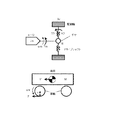
図1は、第1実施形態における電動車両の制御装置を備えた電気自動車の主要構成を示すブロック図である。本発明の電動車両の制御装置は、車両の駆動源の一部または全部として電動モータを備え、電動モータの駆動力により走行可能な電動車両に適用可能である。電動車両には、電気自動車だけでなく、ハイブリッド自動車や燃料電池自動車も含まれる。特に、本実施形態における電動車両の制御装置は、アクセルペダルの操作のみで車両の加減速や停止を制御することができる車両に適用することができる。この車両ではドライバは、加速時にアクセルペダルを踏み込み、減速時や停止時には、踏み込んでいるアクセルペダルの踏み込み量を減らすか、または、アクセルペダルの踏み込み量をゼロとする。なお、登坂路においては、車両の後退を防ぐためにアクセルペダルを踏み込みつつ停止状態に近づく場合もある。
[First Embodiment]
FIG. 1 is a block diagram showing a main configuration of an electric vehicle provided with a control device for an electric vehicle according to the first embodiment. The control device for an electric vehicle of the present invention is applicable to an electric vehicle that includes an electric motor as a part or all of a drive source of the vehicle and can travel by the driving force of the electric motor. Electric vehicles include not only electric vehicles but also hybrid vehicles and fuel cell vehicles. In particular, the control device for an electric vehicle according to the present embodiment can be applied to a vehicle that can control acceleration / deceleration and stop of the vehicle only by operating the accelerator pedal. In this vehicle, the driver depresses the accelerator pedal when accelerating, and reduces the depressing amount of the accelerator pedal when decelerating or stopping, or sets the depressing amount of the accelerator pedal to zero. On an uphill road, the vehicle may approach a stopped state while depressing the accelerator pedal in order to prevent the vehicle from moving backward.
モータコントローラ2は、車速V、アクセル開度θ、モータ(三相交流モータ)4の回転子位相α、モータ4の三相交流電流iu、iv、iw等の車両状態を示す信号がデジタル信号として入力される。モータコントローラ2は、入力された信号に基づいて、モータ4を制御するためのPWM信号を生成する。また、モータコントローラ2は、生成したPWM信号に応じてインバータ3のスイッチング素子を開閉制御する。モータコントローラ2はさらに、ドライバによるアクセル操作量、あるいは、ブレーキペダル10の操作量に応じて、摩擦制動量指令値を生成する。
In the motor controller 2, signals indicating the vehicle state such as vehicle speed V, accelerator opening degree θ, rotor phase α of the motor (three-phase AC motor) 4, and three-phase AC currents iu, iv, and iw of the motor 4 are used as digital signals. Entered. The motor controller 2 generates a PWM signal for controlling the motor 4 based on the input signal. Further, the motor controller 2 controls the opening and closing of the switching element of the inverter 3 according to the generated PWM signal. The motor controller 2 further generates a friction braking amount command value according to the accelerator operation amount by the driver or the operation amount of the
インバータ3は、相ごとに備えられた2個のスイッチング素子(例えば、IGBTやMOS−FET等のパワー半導体素子)をオン/オフすることにより、バッテリ1から供給される直流の電流を交流に変換し、モータ4に所望の電流を流す。
The inverter 3 converts the direct current supplied from the
モータ4は、インバータ3から供給される交流電流により駆動力を発生し、減速機5およびドライブシャフト8を介して、左右の駆動輪9a、9bに駆動力を伝達する。また、モータ4は、車両の走行時に駆動輪9a、9bに連れ回されて回転するときに、回生駆動力を発生させることで、車両の運動エネルギーを電気エネルギーとして回収する。この場合、インバータ3は、モータ4の回生運転時に発生する交流電流を直流電流に変換して、バッテリ1に供給する。
The motor 4 generates a driving force by an alternating current supplied from the inverter 3, and transmits the driving force to the left and
電流センサ7は、モータ4に流れる3相交流電流Iu、Iv、Iwを検出する。ただし、3相交流電流Iu、Iv、Iwの和は0であるため、任意の2相の電流を検出して、残りの1相の電流は演算により求めても良い。 The current sensor 7 detects the three-phase alternating currents Iu, Iv, and Iw flowing through the motor 4. However, since the sum of the three-phase alternating currents Iu, Iv, and Iw is 0, the current of any two phases may be detected and the current of the remaining one phase may be obtained by calculation.
回転センサ6は、例えばレゾルバやエンコーダであり、モータ4の回転子位相αを検出する。
The
ブレーキコントローラ11は、モータコントローラ2で生成された摩擦制動量指令値に応じたブレーキ液圧を発生させるブレーキアクチュエータ指令値を摩擦ブレーキ13に出力する。
The
液圧センサ12は、ブレーキ制動量検出手段として機能し、摩擦ブレーキ13のブレーキ液圧を検出して、検出したブレーキ液圧(摩擦制動量)をブレーキコントローラ11とモータコントローラ2へ出力する。
The
摩擦ブレーキ13は、摩擦制動部として機能する。具体的には、摩擦ブレーキ13は、左右の駆動輪9a、9bにそれぞれ設けられ、ブレーキ液圧に応じてブレーキパッドをブレーキロータに押しつけて、車両に制動力を発生させる。
The
前後Gセンサ15は、主に前後加速度を検出し、検出値をモータコントローラ2へ出力する。これにより、モータコントローラ2は、前後Gセンサ検出値に基づいて、車両の前後方向の傾斜状態を検出できるとともに、モータ4に作用する勾配抵抗と概ね一致する外乱トルク成分を算出することができる。
The front-
図2は、モータコントローラ2によって実行されるようにプログラムされたモータ電流制御の処理の流れを示すフローチャートである。 FIG. 2 is a flowchart showing a processing flow of motor current control programmed to be executed by the motor controller 2.
ステップS201では、車両状態を示す信号がモータコントローラ2に入力される。ここでは、車速V(m/s)、アクセル開度θ(%)、モータ4の回転子位相α(rad)、モータ4の回転速度Nm(rpm)、モータ4に流れる三相交流電流iu、iv、iw、バッテリ1とインバータ3間の直流電圧値Vdc(V)、ブレーキ操作量、及び、ブレーキ液圧が入力される。
In step S201, a signal indicating the vehicle state is input to the motor controller 2. Here, the vehicle speed V (m / s), the accelerator opening degree θ (%), the rotor phase α (rad) of the motor 4, the rotation speed Nm (rpm) of the motor 4, and the three-phase direct current iu flowing through the motor 4. The iv, iv, the DC voltage value V dc (V) between the
車速V(km/h)は、車両駆動時において駆動力を伝達する車輪(駆動輪9a、9b)の車輪速ωwから取得することができる。車速Vは、車輪速センサ11a、11bや、図示しない他のコントローラより通信にて取得される。または、車速V(km/h)は、回転子機械角速度ωmにタイヤ動半径rを乗算し、ファイナルギヤのギヤ比で除算することにより車速v(m/s)を求め、3600/1000を乗算することにより単位変換して求められる。
The vehicle speed V (km / h) can be obtained from the wheel speed ωw of the wheels (driving
アクセル開度θ(%)は、ドライバによるアクセル操作量を示す指標として、図示しないアクセル開度センサから取得されるか、図示しない車両コントローラ等の他のコントローラから通信にて取得される。 The accelerator opening degree θ (%) is acquired from an accelerator opening degree sensor (not shown) or by communication from another controller such as a vehicle controller (not shown) as an index indicating the amount of accelerator operation by the driver.
モータ4の回転子位相α(rad)は、回転センサ6から取得される。モータ4の回転速度Nm(rpm)は、回転子角速度ω(電気角)をモータ4の極対数pで除算して、モータ4の機械的な角速度であるモータ回転速度ωm(rad/s)を求め、求めたモータ回転速度ωmに60/(2π)を乗算することによって求められる。回転子角速度ωは、回転子位相αを微分することによって求められる。
The rotor phase α (rad) of the motor 4 is acquired from the
モータ4に流れる三相交流電流iu、iv、iw(A)は、電流センサ7から取得される。 The three-phase alternating currents iu, iv, and iwa (A) flowing through the motor 4 are acquired from the current sensor 7.
直流電圧値Vdc(V)は、バッテリ1とインバータ3間の直流電源ラインに設けられた電圧センサ(不図示)、または、バッテリコントローラ(不図示)から送信される電源電圧値から求められる。
The DC voltage value V dc (V) is obtained from the power supply voltage value transmitted from the voltage sensor (not shown) provided in the DC power supply line between the
ブレーキ制動量は、液圧センサ12が検出したブレーキ液圧センサ値から取得される。あるいは、ドライバのペダル操作によるブレーキペダルの踏み込み量を検出するストロークセンサ(不図示)等による検出値(ブレーキ操作量)がブレーキ制動量として使用されても良い。
The brake braking amount is acquired from the brake hydraulic pressure sensor value detected by the
ステップS202のトルク目標値算出処理では、モータコントローラ2が第1のトルク目標値Tm1*を設定する。具体的には、まず初めに、ステップS201で入力されたアクセル開度θおよびモータ回転速度ωmに応じて算出される駆動力特性の一態様を表した図3に示すアクセル開度−トルクテーブルを参照することにより、ドライバ要求トルクとしての基本トルク目標値Tm0*(トルク目標値)が設定される。続いて、勾配抵抗と概ね一致する外乱トルク推定値Tdを求める。そして、基本トルク目標値Tm0*と外乱トルク推定値Tdとを加算することによって、勾配抵抗成分がキャンセルされた第1のトルク目標値Tm1*が設定される。 In the torque target value calculation process in step S202, the motor controller 2 sets the first torque target value Tm1 *. Specifically, first, the accelerator opening-torque table shown in FIG. 3 showing one aspect of the driving force characteristics calculated according to the accelerator opening θ and the motor rotation speed ωm input in step S201 is displayed. By referring to it, the basic torque target value Tm0 * (torque target value) as the driver required torque is set. Subsequently, the disturbance torque estimated value Td that substantially matches the gradient resistance is obtained. Then, by adding the basic torque target value Tm0 * and the disturbance torque estimated value Td, the first torque target value Tm1 * in which the gradient resistance component is canceled is set.
なお、上述したように、本実施形態における電動車両の制御装置は、アクセルペダルの操作のみで車両の加減速や停止を制御することができる車両に適用可能であり、少なくともアクセルペダルの全閉によって車両を停止させることが可能である。そのため、図3に示すアクセル開度−トルクテーブルでは、アクセル開度が0(全閉)あるいは1/8の時には、回生制動力が働くように負のモータトルクが設定されている。ただし、図3に示すアクセル開度−トルクテーブルは一例であって、これに限定されない。 As described above, the control device for the electric vehicle according to the present embodiment can be applied to a vehicle that can control acceleration / deceleration and stop of the vehicle only by operating the accelerator pedal, and at least by fully closing the accelerator pedal. It is possible to stop the vehicle. Therefore, in the accelerator opening-torque table shown in FIG. 3, when the accelerator opening is 0 (fully closed) or 1/8, a negative motor torque is set so that the regenerative braking force acts. However, the accelerator opening-torque table shown in FIG. 3 is an example and is not limited thereto.
ステップS203では、コントローラ2が停止制御処理を行う。具体的には、コントローラ2が、停車間際か否かを判定し、停車間際でない場合は、ステップS202で算出した第1のトルク目標値Tm1*をモータトルク指令値Tm*に設定し、停車間際の場合は、第2のトルク目標値Tm2*をモータトルク指令値Tm*に設定する。この第2のトルク目標値Tm2*は、モータ回転速度の低下とともに外乱トルク推定値Td、或いは後述する外乱補正トルクに収束するものであって、登坂路では正トルク、降坂路では負トルク、平坦路では概ねゼロである。これにより、路面の勾配に関わらず、停車状態を維持することができる。 In step S203, the controller 2 performs the stop control process. Specifically, the controller 2 determines whether or not the vehicle is about to stop, and if it is not about to stop, the first torque target value Tm1 * calculated in step S202 is set to the motor torque command value Tm *, and the vehicle is about to stop. In the case of, the second torque target value Tm2 * is set to the motor torque command value Tm *. This second torque target value Tm2 * converges to the disturbance torque estimated value Td or the disturbance correction torque described later as the motor rotation speed decreases, and is positive torque on an uphill road, negative torque on a downhill road, and flat. It is almost zero on the road. As a result, the stopped state can be maintained regardless of the slope of the road surface.
続くステップS204では、コントローラ2が電流指令値算出処理を行う。具体的には、ステップS203で算出したトルク目標値Tm*(モータトルク指令値Tm*)に加え、モータ回転速度ωmや直流電圧値Vdcに基づいて、d軸電流目標値id*、q軸電流目標値iq*を求める。例えば、トルク指令値、モータ回転速度、および直流電圧値と、d軸電流目標値およびq軸電流目標値との関係を定めたテーブルを予め用意しておいて、このテーブルを参照することにより、d軸電流目標値id*およびq軸電流目標値iq*を求める。 In the following step S204, the controller 2 performs a current command value calculation process. Specifically, in addition to the torque target value Tm * (motor torque command value Tm * ) calculated in step S203, the d-axis current target value id * and the q-axis current are based on the motor rotation speed ωm and the DC voltage value Vdc. Find the target value iq * . For example, by preparing in advance a table that defines the relationship between the torque command value, the motor rotation speed, and the DC voltage value, and the d-axis current target value and the q-axis current target value, by referring to this table, Obtain the d-axis current target value id * and the q-axis current target value iq *.
ステップS205では、d軸電流idおよびq軸電流iqをそれぞれ、ステップS204で求めたd軸電流目標値id*およびq軸電流目標値iq*と一致させるための電流制御を行う。このため、まず初めに、ステップS201で入力された三相交流電流iu、iv、iwと、電動モータ4の回転子位相αとに基づいて、d軸電流idおよびq軸電流iqを求める。続いて、d軸、q軸電流指令値id*、iq*と、d軸、q軸電流id、iqとの偏差から、d軸、q軸電圧指令値vd、vqを算出する。なお、算出したd軸、q軸電圧指令値vd、vqに対して、d−q直交座標軸間の干渉電圧を相殺するために必要な非干渉電圧を加算するようにしてもよい。 In step S205, current control is performed to match the d-axis current id and the q-axis current iq with the d-axis current target value id * and the q-axis current target value iq * obtained in step S204, respectively. Therefore, first, the d-axis current id and the q-axis current iq are obtained based on the three-phase AC currents iu, iv, and iwa input in step S201 and the rotor phase α of the electric motor 4. Subsequently, the d-axis and q-axis voltage command values vd and vq are calculated from the deviations between the d-axis and q-axis current command values id * and iq * and the d-axis and q-axis current id and iq. The non-interference voltage required for canceling the interference voltage between the dq orthogonal coordinate axes may be added to the calculated d-axis and q-axis voltage command values vd and vq.
そして、d軸、q軸電圧指令値vd、vqと、電動モータ4の回転子位相αから、三相交流電圧指令値vu、vv、vwを求める。求めた三相交流電圧指令値vu、vv、vwと直流電圧値Vdcから、PWM信号tu(%)、tv(%)、tw(%)を求める。このようにして求めたPWM信号tu、tv、twにより、インバータ3のスイッチング素子を開閉することによって、電動モータ4をモータトルク指令値Tm*で指示された所望のトルクで駆動することができる。 Then, the three-phase AC voltage command values vu, vv, and vw are obtained from the d-axis and q-axis voltage command values vd and vq and the rotor phase α of the electric motor 4. From the obtained three-phase AC voltage command values vu, vv, vw and the DC voltage value Vdc, the PWM signals tu (%), tv (%), and tw (%) are obtained. By opening and closing the switching element of the inverter 3 by the PWM signals tu, tv, and tw obtained in this way, the electric motor 4 can be driven with a desired torque instructed by the motor torque command value Tm *.
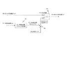
図2のステップS202で行われる処理、すなわち、第1のトルク目標値Tm1*を設定する方法の詳細を、図4を用いて説明する。 The details of the process performed in step S202 of FIG. 2, that is, the method of setting the first torque target value Tm1 * will be described with reference to FIG.
基本トルク目標値設定器401は、アクセル開度およびモータ回転速度ωmに基づいて、図3に示すアクセル開度−トルクテーブルを参照することにより、基本トルク目標値Tm0*を設定する。 The basic torque target value setter 401 sets the basic torque target value Tm0 * by referring to the accelerator opening degree-torque table shown in FIG. 3 based on the accelerator opening degree and the motor rotation speed ωm.
外乱トルク推定器402は、モータトルク指令値Tm*とモータ回転速度ωmとブレーキ制動量Bとに基づいて、外乱トルク推定値Tdを求める。
The
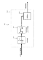
図5は、外乱トルク推定器402の詳細な構成を示すブロック図である。外乱トルク推定器402は、制御ブロック501と、制御ブロック502と、減算器503と、制御ブロック504とを備える。
FIG. 5 is a block diagram showing a detailed configuration of the
制御ブロック501は、H(s)/Gp(s)なる伝達特性を有するフィルタとしての機能を担っており、モータ回転速度ωmを入力してフィルタリング処理を行うことにより、第1のモータトルク推定値を算出する。Gp(s)は、モータトルクTmからモータ回転速度ωmまでの伝達特性であり、詳細については後述する。H(s)は、分母次数と分子次数との差分が、モデルGr(s)の分母次数と分子次数との差分以上となる伝達特性を有するローパスフィルタである。なお、図5で図示する制御ブロック上、及び、上記の説明においては、モータ回転速度ωmから第1のモータトルク推定値を算出する旨説明したが、モータ回転速度ωmに比例する速度パラメータとしての車輪速ωwから、第1のモータトルク推定値を算出してもよい。
The
制御ブロック502は、H(s)なる伝達特性を有するローパスフィルタとしての機能を担っており、モータトルク指令値Tm*を入力してフィルタリング処理を行うことにより、第2のモータトルク推定値を算出する。
The
減算器503は、第2のモータトルク推定値から第1のモータトルク推定値を減算することによって、外乱トルク推定値Tdを算出する。この外乱トルク推定値Tdは、概ね勾配抵抗と一致する値となり、登坂路では正トルク、降坂路では負トルク、平坦路では概ねゼロとなる。
The
本実施形態では、第2のモータトルク推定値と第1のモータトルク推定値との偏差に対して、制御ブロック504によりフィルタリング処理を施すことにより、外乱トルク推定値Tdを算出する。制御ブロック504は、Hz(s)なる伝達特性を有するフィルタとしての機能を担っており、第2のモータトルク推定値と第1のモータトルク推定値との偏差を入力してフィルタリング処理を行うことにより、外乱トルク推定値Tdを算出する。Hz(s)の詳細については、後述する。
In the present embodiment, the disturbance torque estimated value Td is calculated by filtering the deviation between the second motor torque estimated value and the first motor torque estimated value by the
図4に戻って説明を続ける。外乱トルク推定器402にて算出された外乱トルク推定値Tdは、通常であれば加算器404に入力されて、基本トルク目標値Tm0*に加算される。これにより、基本トルク目標値Tm0*に対して、外乱トルク推定値Tdに基づく勾配補正が行われ、勾配抵抗成分がキャンセルされた第1のトルク目標値Tm1*が算出される。
The explanation will be continued by returning to FIG. The disturbance torque estimate value Td calculated by the
ここで、外乱トルク推定値Tdは、車両の駆動力伝達系を模した車両モデル(詳細は後述する)を用いて、モータ回転速度ωm、或いは、車輪速ωwと、モータトルク指令値Tm*とに基づいて推定される。ところが、例えば車両の整備時に駆動輪がジャッキアップされた際は、該車両モデルを構成するパラメータが、実際の車両状態と極端に相違する。この状態でアクセル操作や他の外力により駆動輪が回転すると、路面との摩擦がない状態で駆動輪が回転するので、モータトルクに対して、モータ回転速度、或いは車輪速が相対的に高く検出されてしまう。その結果、外乱トルク推定値Tdが誤推定され、車両が降坂路を走行中であると誤認識するため、モータに制動トルクを出力させる方向(回生側)での勾配補正が実行されてしまう。そうすると、今度は、モータトルク指令値に対してモータ回転速度、或いは車輪速が低く検出されるので、車両が登坂路を走行中であると誤推定し、モータに駆動トルクを出力させる方向(力行側)での勾配補正が実行されてしまう。 Here, the disturbance torque estimated value Td is a motor rotation speed ωm or a wheel speed ωw and a motor torque command value Tm *, using a vehicle model (details will be described later) that imitates the driving force transmission system of the vehicle. Estimated based on. However, for example, when the drive wheels are jacked up during maintenance of the vehicle, the parameters constituting the vehicle model are extremely different from the actual vehicle state. If the drive wheels rotate due to accelerator operation or other external force in this state, the drive wheels rotate without friction with the road surface, so the motor rotation speed or wheel speed is detected to be relatively high with respect to the motor torque. Will be done. As a result, the disturbance torque estimated value Td is erroneously estimated, and it is erroneously recognized that the vehicle is traveling on a downhill road, so that the gradient correction is executed in the direction (regeneration side) in which the motor outputs the braking torque. Then, since the motor rotation speed or the wheel speed is detected to be lower than the motor torque command value, it is erroneously estimated that the vehicle is traveling on an uphill road, and the motor is made to output the drive torque (power running). Gradient correction on the side) is executed.
このように、車両の駆動輪がジャッキアップされた際や、凍結路面等の低μ路などを走行する時等、車輪と路面との間に作用する摩擦力が通常走行時よりも低下する場面で、実際の車両状態と車両モデルとが極端に相違する場合には、外乱トルクを正確に推定することができない。また、外乱トルクを正確に推定できないだけではなく、降坂路から登坂路、またはその逆の方向への誤推定が繰り返されることにより、外乱トルク推定値Tdが正負に異常変動し、これに起因して車両に自励振動が発生する場合がある。 In this way, when the drive wheels of the vehicle are jacked up, or when traveling on a low μ road such as an icy road surface, the frictional force acting between the wheels and the road surface is lower than during normal driving. Therefore, if the actual vehicle condition and the vehicle model are extremely different, the disturbance torque cannot be estimated accurately. In addition, not only the disturbance torque cannot be estimated accurately, but also the disturbance torque estimated value Td fluctuates abnormally positively and negatively due to repeated erroneous estimation from the downhill road to the uphill road or vice versa. Self-excited vibration may occur in the vehicle.
このようにして発生し得る自励振動を抑制するために、本実施形態に係る電動車両の制御装置は、外乱トルク推定値Tdが異常値であるか否かを判定し、外乱トルク推定値Tdが異常と判定された場合には勾配補正を中止する補正可否判断処理を実行する。補正可否判断処理を実行するための構成について、以下説明を続ける。 In order to suppress the self-excited vibration that may occur in this way, the control device for the electric vehicle according to the present embodiment determines whether or not the disturbance torque estimated value Td is an abnormal value, and determines whether or not the disturbance torque estimated value Td is an abnormal value. If is determined to be abnormal, the correction propriety determination process for canceling the gradient correction is executed. The configuration for executing the correction possibility determination process will be described below.
図4に図示する外乱推定トルク異常判定器405は、外乱トルク推定器402にて推定された外乱トルク推定値Tdの変動周波数から、外乱トルク推定値Tdが異常値であるか否かを判定する。外乱推定トルク異常判定器405は、外乱トルク推定値Tdが異常値であると判定すると、勾配補正を中止するために、勾配補正中止フラグを1に設定して、外乱補正トルク設定器406に出力する。外乱推定トルク異常判定器405において実行される補正可否判断処理の詳細については後述する。
The disturbance estimation torque
外乱補正トルク設定器406は、外乱推定トルク異常判定器405の出力値である勾配補正中止フラグに応じて、外乱補正トルクを設定する。勾配外乱補正中止フラグが0(初期値)の場合は、外乱トルク推定値Tdは正常と判定されるので、通常通り外乱トルク推定値Tdを外乱補正トルクに設定する。勾配外乱補正中止フラグが1の場合は、外乱トルク推定値Tdは異常と判定されるので、外乱トルク推定値Tdに基づく勾配補正を中止するために外乱補正トルクを0に設定する。
The disturbance correction
加算器404は、基本トルク目標値設定器401で算出された基本トルク目標値Tm0*と外乱補正トルクとを加算することにより、第1のトルク目標値Tm1*を算出する。これにより、勾配外乱補正中止フラグが0の場合は、外乱トルク推定値Tdに基づく勾配補正がなされた第1のトルク目標値Tm1*が算出される。そして、外乱トルク推定値Tdが異常値を示すために勾配外乱補正中止フラグが1に設定された場合は、勾配補正は行われず、ドライバ要求トルクとしての基本トルク目標値Tm0*が、そのままモータトルク指令値Tm*として設定される。
The
続いて、本実施形態における電動車両の制御装置において、モータトルクTmからモータ回転速度ωmまでの伝達特性Gp(s)について説明する。なお、この伝達特性Gp(s)は、外乱トルク推定値を算出する際に、車両の駆動力伝達系をモデル化した車両モデルとして用いられる。 Subsequently, in the control device for the electric vehicle according to the present embodiment, the transmission characteristic Gp (s) from the motor torque Tm to the motor rotation speed ωm will be described. The transmission characteristic G p (s) is used as a vehicle model that models the driving force transmission system of the vehicle when calculating the disturbance torque estimated value.
図6は、車両の駆動力伝達系をモデル化した図であり、同図における各パラメータは、以下に示すとおりである。
Jm:電動モータのイナーシャ
Jw:駆動輪のイナーシャ
M:車両の重量
Kd:駆動系の捻り剛性
Kt:タイヤと路面の摩擦に関する係数
N:オーバーオールギヤ比
r:タイヤの荷重半径
ωm:モータ回転速度
Tm:トルク目標値Tm*
Td:駆動輪のトルク
F:車両に加えられる力
V:車両の速度
ωw:駆動輪の角速度(車輪速)
そして、図6より、以下の運動方程式を導くことができる。
FIG. 6 is a diagram modeling a driving force transmission system of a vehicle, and each parameter in the figure is as shown below.
J m : Electric motor inertia J w : Drive wheel inertia M: Vehicle weight K d : Drive system torsional rigidity K t : Coefficient related to friction between tire and road surface N: Overall gear ratio r: Tire load radius ω m : Motor rotation speed T m : Torque target value T m *
T d : Drive wheel torque F: Force applied to the vehicle V: Vehicle speed ω w : Drive wheel angular velocity (wheel speed)
Then, from FIG. 6, the following equation of motion can be derived.

![]()
![]()
![]()
![]()
![]()
![]()
ただし、式(1)〜(3)中の符号の右上に付されているアスタリスク(*)は、時間微分を表している。 However, the asterisk (* ) attached to the upper right of the code in the equations (1) to (3) represents the time derivative.
式(1)〜(5)で示す運動方程式に基づいて、モータ4のモータトルクTmからモータ回転速度ωmまでの伝達特性Gp(s)を求めると、次式(6)で表される。 When the transmission characteristic Gp (s) from the motor torque Tm of the motor 4 to the motor rotation speed ωm is obtained based on the equations of motion represented by the equations (1) to (5), it is expressed by the following equation (6).
ただし、式(6)中の各パラメータは、次式(7)で表される。 However, each parameter in the equation (6) is represented by the following equation (7).
式(6)に示す伝達関数の極と零点を調べると、次式(8)の伝達関数に近似することができ、1つの極と1つの零点は極めて近い値を示す。これは、次式(8)のαとβが極めて近い値を示すことに相当する。 By examining the poles and zeros of the transfer function shown in equation (6), it can be approximated to the transfer function of equation (8), and one pole and one zero show extremely close values. This corresponds to the fact that α and β in the following equation (8) show extremely close values.
従って、式(8)における極零相殺(α=βと近似する)を行うことにより、次式(9)に示すように、Gp(s)は、(2次)/(3次)の伝達特性を構成する。 Therefore, by performing the pole-zero cancellation (approximate to α = β) in the equation (8), Gp (s) is the transmission of (second order) / (third order) as shown in the following equation (9). Configure the characteristics.
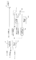
続いて、図7、8を参照して、ステップS203で実行される停止制御処理の詳細について説明する。 Subsequently, the details of the stop control process executed in step S203 will be described with reference to FIGS. 7 and 8.
<停止制御処理>
図7は、停止制御処理を実現するためのブロック図である。停止制御処理は、モータ回転速度F/Bトルク設定器701と、加算器703と、トルク比較器704とを用いて行われる。以下、それぞれの構成の詳細を説明する。
<Stop control processing>
FIG. 7 is a block diagram for realizing the stop control process. The stop control process is performed using the motor rotation speed F / B
モータ回転速度F/Bトルク設定器701は、検出されたモータ回転速度ωmに基づいて、モータ回転速度フィードバックトルク(以下、モータ回転速度F/Bトルクと呼ぶ)Tωを算出する。詳細は図8を用いて説明する。
The motor rotation speed F /
図8は、モータ回転速度ωmに基づいて、モータ回転速度F/BトルクTωを算出する方法を説明するための図である。モータ回転速度F/Bトルク設定器701は、乗算器801を備え、モータ回転速度ωmにゲインKvrefを乗算することにより、モータ回転速度F/BトルクTωを算出する。ただし、Kvrefは、電動車両の停止間際に電動車両を停止させるのに必要な負(マイナス)の値であり、例えば、実験データ等により適宜設定される。モータ回転速度F/BトルクTωは、モータ回転速度ωmが大きいほど、大きい制動力が得られるトルクとして設定される。
FIG. 8 is a diagram for explaining a method of calculating the motor rotation speed F / B torque Tω based on the motor rotation speed ωm. The motor rotation speed F / B
なお、モータ回転速度F/Bトルク設定器701は、モータ回転速度ωmにゲインKvrefを乗算することによりモータ回転速度F/BトルクTωを算出するものとして説明したが、モータ回転速度ωmに対する回生トルクを定めた回生トルクテーブルや、モータ回転速度ωmの減衰率を予め記憶した減衰率テーブル等を用いて、モータ回転速度F/BトルクTωを算出してもよい。
Although the motor rotation speed F / B
図7に戻って説明を続ける。加算器703は、モータ回転速度F/Bトルク設定器701によって算出されたモータ回転速度F/BトルクTωと、上述した外乱補正トルク設定器406の出力値である外乱補正トルクとを加算することによって、第2のトルク目標値Tm2*を算出する。外乱補正トルクは外乱トルク推定値Tdに応じて設定される値であって、詳細は図4を用いて上述した通りである。
The explanation will be continued by returning to FIG. The
ここで、外乱トルク推定値Tdに関して、図5に示した制御ブロック504の詳細を説明する。制御ブロック504は、Hz(s)なる伝達特性を有するフィルタであり、減算器503の出力を入力してフィルタリング処理を行う事により、外乱トルク推定値Tdを算出する。
Here, the details of the control block 504 shown in FIG. 5 will be described with respect to the disturbance torque estimated value Td. The
伝達特性Hz(s)について説明する。式(9)を書き換えると、次式(10)が得られる。ただし、式(10)中のζz、ωz、ζp、ωpはそれぞれ、式(11)で表される。 The transmission characteristic Hz (s) will be described. By rewriting the equation (9), the following equation (10) is obtained. However, ζz, ωz, ζp, and ωp in the equation (10) are represented by the equation (11), respectively.
以上より、Hz(s)を次式(12)で表す。ただし、ζc>ζzとする。また、ギヤのバックラッシュを伴う減速シーンで振動抑制効果を高めるために、ζc>1とする。 From the above, Hz (s) is represented by the following equation (12). However, ζ c > ζ z . Further, in order to enhance the vibration suppression effect in a deceleration scene accompanied by gear backlash, ζ c > 1.
このように、本実施形態では、外乱トルクは、図5に示す通り、外乱オブザーバにより推定される。 As described above, in the present embodiment, the disturbance torque is estimated by the disturbance observer as shown in FIG.
ここで、外乱としては、空気抵抗、乗員数や積載量に起因する車両質量の変動によるモデル化誤差、タイヤの転がり抵抗、路面の勾配抵抗等が考えられるが、停車間際で支配的となる外乱要因は勾配抵抗である。外乱要因は運転条件により異なるが、外乱トルク推定器402は、モータトルク指令値Tm*とモータ回転速度ωmと、車両モデルGp(s)に基づいて、外乱トルク推定値Tdを算出するので、上述した外乱要因を一括して推定することができる。これにより、上述の車両モデルと実車両の駆動力伝達系が概ね一致している限り、いかなる運転条件においても、減速からの滑らかな停車を実現することができる。
Here, as the disturbance, air resistance, modeling error due to fluctuation of vehicle mass due to the number of occupants and the load capacity, rolling resistance of tires, gradient resistance of the road surface, etc. can be considered, but the disturbance that becomes dominant just before the vehicle stops. The factor is gradient resistance. The disturbance factor differs depending on the operating conditions, but the
図7に戻って説明を続ける。加算器703は、モータ回転速度F/Bトルク設定器701によって算出されたモータ回転速度F/BトルクTωと、外乱補正トルクとを加算することによって、第2のトルク目標値Tm2*を算出する。
The explanation will be continued by returning to FIG. The adder 703 calculates the second torque target value Tm2 * by adding the motor rotation speed F / B torque Tω calculated by the motor rotation speed F /
トルク比較器704は、第1のトルク目標値Tm1*と第2のトルク目標値Tm2*の大きさを比較し、値が大きい方のトルク目標値をモータトルク指令値Tm*に設定する。車両の走行中、第2のトルク目標値Tm2*は第1のトルク目標値Tm1*よりも小さく、車両が減速して停車間際(車速、或いは車速に比例する速度パラメータが所定値以下)になると、第1のトルク目標値Tm1*よりも大きくなる。従って、トルク比較器704は、第1のトルク目標値Tm1*が第2のトルク目標値Tm2*より大きければ、停車間際以前と判断して、モータトルク指令値Tm*を第1のトルク目標値Tm1*に設定する。また、トルク比較器704は、第2のトルク目標値Tm2*が第1のトルク目標値Tm1*より大きくなると、車両が停車間際と判断して、モータトルク指令値Tm*を第1のトルク目標値Tm1*から第2のトルク目標値Tm2*に切り替える。なお、停車状態を維持するため、第2のトルク目標値Tm2*は、登坂路では正トルク、降坂路では負トルク、平坦路では概ねゼロに収束する。
The
以上、伝達特性Gp(s)及び停止制御処理の詳細について説明した。上述した通り、車両の駆動輪がジャッキアップされた際などでは、上記車両モデルを構成する車重や、路面との摩擦係数等のパラメータが、実際の車両状態と極端に相違する場合がある。本実施形態では、このような場面で誤推定された外乱トルク推定値に起因して発生し得る自励振動を抑制するために補正可否判断処理を実行する。以下、外乱推定トルク異常判定器405(図4参照)において実行される補正可否判断処理の詳細を説明する。 The details of the transmission characteristic G p (s) and the stop control process have been described above. As described above, when the drive wheels of the vehicle are jacked up, parameters such as the vehicle weight constituting the vehicle model and the coefficient of friction with the road surface may be extremely different from the actual vehicle condition. In the present embodiment, the correction possibility determination process is executed in order to suppress the self-excited vibration that may occur due to the disturbance torque estimated value erroneously estimated in such a situation. Hereinafter, the details of the correction possibility determination process executed by the disturbance estimation torque abnormality determination device 405 (see FIG. 4) will be described.
図9は、第1実施形態における補正可否判断処理の流れを示すフローチャートである。当該フローは、モータコントローラ2において、一定のサイクルで繰り返し実行されるようにプログラムされている。 FIG. 9 is a flowchart showing the flow of the correction possibility determination process in the first embodiment. The flow is programmed in the motor controller 2 to be repeatedly executed in a fixed cycle.
ステップS801では、モータコントローラ2が、外乱トルク推定値Tdの変動周波数を検出する。なお、外乱トルク推定値Tdは、図5を参照して説明した外乱オブザーバを用いて算出される。 In step S801, the motor controller 2 detects the fluctuation frequency of the disturbance torque estimated value Td. The disturbance torque estimated value Td is calculated using the disturbance observer described with reference to FIG.
続くステップS802では、モータコントローラ2が、検出した外乱トルク推定値Tdの変動周波数から、該外乱トルク推定値Tdが異常か否かを判定する。 In the following step S802, the motor controller 2 determines whether or not the disturbance torque estimated value Td is abnormal from the fluctuation frequency of the detected disturbance torque estimated value Td.
ここで、外乱トルク推定値Tdは、本来、車両が路面を走行する際の路面勾配に応じて算出される値である。また、外乱トルク推定値Tdは、登坂路では正の符号を持ち、降坂路では負の符号を持つ。したがって、外乱トルク推定値Tdの符号の正負の変動周波数と実際に車両が走行する路面状態との比較に基づいて、外乱トルク推定値Tdの異常を検知することができる。例えば、通常車両が走行する路面において、1秒の間に登坂路から降坂路へ、或いはその逆への変化を繰り返すことはほぼない。したがって、外乱トルク推定値Tdの正負の変動周波数(以下単に変動周波数と呼ぶ)が例えば1Hz以上であれば、当該外乱トルク推定値Tdは異常値と判断することができる。なお、ここで示した1Hzは例示であって、それ以下、あるいはそれ以上の周波数が外乱トルク推定値Tdの異常を判断し得る周波数として設定されてもよい。 Here, the disturbance torque estimated value Td is originally a value calculated according to the road surface gradient when the vehicle travels on the road surface. Further, the disturbance torque estimated value Td has a positive sign on the uphill road and a negative sign on the downhill road. Therefore, the abnormality of the disturbance torque estimated value Td can be detected based on the comparison between the positive and negative fluctuation frequencies of the sign of the disturbance torque estimated value Td and the road surface condition in which the vehicle actually travels. For example, on a road surface on which a normal vehicle travels, the change from an uphill road to a downhill road and vice versa is rarely repeated in one second. Therefore, if the positive / negative fluctuation frequency of the disturbance torque estimated value Td (hereinafter, simply referred to as the fluctuation frequency) is, for example, 1 Hz or more, the disturbance torque estimated value Td can be determined to be an abnormal value. Note that 1 Hz shown here is an example, and a frequency lower than or higher than that may be set as a frequency at which an abnormality of the disturbance torque estimated value Td can be determined.
ステップS802では、モータコントローラ2は、外乱トルク推定値Tdの変動周波数が1Hz以上であれば、当該外乱トルク推定値Tdは異常値と判定し、当該異常が所定時間継続するか否かを判定するために続くステップS803の処理を実行する。外乱推定トルクの変動周波数が1Hzより小さければ、勾配補正を実行するために、ステップS804の処理を実行する。 In step S802, if the fluctuation frequency of the disturbance torque estimated value Td is 1 Hz or more, the motor controller 2 determines that the disturbance torque estimated value Td is an abnormal value, and determines whether or not the abnormality continues for a predetermined time. Therefore, the process of step S803 that follows is executed. If the fluctuation frequency of the disturbance estimated torque is smaller than 1 Hz, the process of step S804 is executed in order to execute the gradient correction.
ステップS803では、モータコントローラ2は、外乱トルク推定値Tdの変動周波数異常が所定時間以上続くか否かを判定する。本ステップは、外乱トルク推定値Tdが異常値であると誤って判定した場合に、勾配補正を無用に中止することを防ぐための処理である。また例えば、外乱トルク推定値Tdが異常な振動を示しても、該振動がすぐに収束する場合は、勾配補正を必ずしも中止する必要はない。このような場合でも、本ステップの処理を実行することにより勾配補正を無用に中止するのを防ぐことができる。ここでの所定時間は、例えば、車両の足上げ時に発生する可能性のある外乱トルク推定値の振動が0に収束する場合の減衰時間を予め測定した値等に応じて設定される。モータコントローラ2は、該変動周波数異常が所定時間以上継続したと判定した場合は、勾配補正を中止するために続くステップS805の処理を実行する。該変動周波数異常が所定時間以上継続していないと判定した場合は、外乱トルク推定値Tdの現在値を算出するためにステップS801の処理を繰り返し実行する。 In step S803, the motor controller 2 determines whether or not the fluctuation frequency abnormality of the disturbance torque estimated value Td continues for a predetermined time or longer. This step is a process for preventing the gradient correction from being unnecessarily stopped when it is erroneously determined that the disturbance torque estimated value Td is an abnormal value. Further, for example, even if the disturbance torque estimated value Td shows an abnormal vibration, if the vibration converges immediately, it is not always necessary to stop the gradient correction. Even in such a case, it is possible to prevent the gradient correction from being unnecessarily stopped by executing the process of this step. The predetermined time here is set according to, for example, a value obtained by previously measuring the damping time when the vibration of the estimated disturbance torque value that may occur when the vehicle is raised is converged to 0. When the motor controller 2 determines that the fluctuation frequency abnormality has continued for a predetermined time or longer, the motor controller 2 executes the process of step S805 that follows in order to stop the gradient correction. When it is determined that the fluctuation frequency abnormality does not continue for a predetermined time or more, the process of step S801 is repeatedly executed in order to calculate the current value of the disturbance torque estimated value Td.
ここで、ステップS801からS803において実行される変動周波数の異常判断を実現する制御ブロックについて、図10、11を参照して説明する。 Here, the control block that realizes the abnormality determination of the fluctuating frequency executed in steps S801 to S803 will be described with reference to FIGS. 10 and 11.
図10、11は、変動周波数の異常判断を実行する外乱推定トルク異常判定器405(図5参照)の構成の一例を示す制御ブロック図である。外乱推定トルク異常判定器405は、例えば、図10に示す半周期カウンタ810と、図11に示す周波数成分抽出フィルタ820と、周波数比較器830と、タイマ840と、から構成される。
10 and 11 are control block diagrams showing an example of the configuration of the disturbance estimation torque abnormality determining device 405 (see FIG. 5) that executes the abnormality determination of the fluctuating frequency. The disturbance estimation torque
半周期カウンタ810は、符号判定器811と、エッジ検出器812と、タイマカウンタ813とから構成され、外乱トルク推定値Tdを入力して、外乱トルク推定値Tdの半周期時間(0跨ぎ後時間)を検出する。より具体的には、符号判定器811が外乱トルク推定値Tdの正負を判定し、エッジ検出器812が外乱トルク推定値Tdの立上りエッジと立下りエッジを検出する。そして、タイマカウンタ813によって、外乱トルク推定値Tdの正あるいは負の立上りエッジと立下りエッジ間に係る0跨ぎ後時間が検出される。このように検出された外乱トルク推定値の半周期時間は、周波数成分抽出フィルタ820(図11参照)に出力される。
The half-cycle counter 810 is composed of a
図11に図示する周波数成分抽出フィルタ820は、下限比較器821と、上限比較器823と、アンド回路824とから構成され、タイマカウンタ813からの半周期時間を入力して、フィルタリング処理を行うことにより、共振近傍半周期時間を算出する。
The frequency
下限比較器821は、半周期時間と、予め設定された半周期時間下限値とを比較して、通常走行時において通常検出し得る路面勾配変化に伴う周波数変動以下の半周期時間をカットする。
The
上限比較器823は、半周期時間と、予め設定された半周期時間上限値とを比較して、チャタリング等により発生する高周波ノイズをカットする。ただし、車両のジャッキアップ時の変動周波数は予め実験等により特定することができるので、下限比較器821と上限比較器823の比較値を、変動周波数の近傍値のみを抽出する値に設定しても良い。
The
そして、アンド回路824は、半周期カウンタ810から出力される半周期時間から半周期時間下限値以上、半周期時間上限値以下の周波数成分(共振近傍半周期)を抽出して、周波数比較器830に出力する。
Then, the AND
周波数比較器830は、共振近傍半周期をカウントして外乱トルク推定値Tdの変動周波数を算出するとともに、外乱トルク推定値Tdの変動周波数が所定の周波数以上か否かを判定する。所定の周波数は、上記の通り例えば1Hzに設定される。そして、外乱推定トルクの変動周波数が所定値以上であれば、外乱推定トルクが異常値であると判断して、外乱推定トルクが異常値であることを示すフラグ(周波数異常フラグ)をタイマ840に出力する。
The
タイマ840は、周波数異常フラグの継続時間をカウントすることにより、外乱トルク推定値Tdの変動周波数異常が所定時間続くか否かを判定する。周波数異常フラグが所定時間以上継続する場合は、勾配補正を中止するためのフラグ(勾配補正中止フラグ)を1に設定して、図4に図示する外乱補正トルク設定器406に出力する。
The
以上の構成により、外乱推定トルク異常判定器405は、外乱トルク推定値Tdの変動周波数が異常値であるか否かを判定することができる。
With the above configuration, the disturbance estimation torque
フローに戻って説明を続ける。ステップS805では、ステップS802において外乱トルク推定値が異常値と判定され、且つ、ステップS803において外乱トルク推定値Tdの異常が所定時間続いたと判定されたため、モータコントローラ2は外乱補正トルクを0に設定することにより勾配補正を中止して、補正可否判断処理を終了する。 Go back to the flow and continue the explanation. In step S805, the disturbance torque estimated value is determined to be an abnormal value in step S802, and it is determined in step S803 that the abnormality of the disturbance torque estimated value Td has continued for a predetermined time. Therefore, the motor controller 2 sets the disturbance correction torque to 0. By doing so, the gradient correction is stopped and the correction approval / disapproval determination process is terminated.
他方、ステップS804では、外乱トルク推定値がその変動周波数から正常値と判定されたため、モータトルク指令値に対する勾配補正を実行するために、外乱補正トルクとしての外乱トルク推定値Tdを設定する。外乱トルク推定値Tdが外乱補正トルクとして設定された後、続くステップS806の処理を実行する。 On the other hand, in step S804, since the disturbance torque estimated value is determined to be a normal value from the fluctuation frequency, the disturbance torque estimated value Td as the disturbance correction torque is set in order to execute the gradient correction with respect to the motor torque command value. After the disturbance torque estimated value Td is set as the disturbance correction torque, the processing of the subsequent step S806 is executed.
ステップS806では、モータコントローラ2は、外乱補正トルクとしての外乱トルク推定値Tdを、ドライバ要求トルクとしての基本トルク目標値Tm0*に加算することにより勾配補正を行う。このようにして勾配補正が実行された後、モータコントローラ2は、補正可否判断処理を終了する。 In step S806, the motor controller 2 corrects the gradient by adding the disturbance torque estimated value Td as the disturbance correction torque to the basic torque target value Tm0 * as the driver required torque. After the gradient correction is executed in this way, the motor controller 2 ends the correction possibility determination process.
以上説明した第1実施形態の電動車両の制御装置を電気自動車に適用した際の効果について、図12を参照して説明する。 The effect of applying the control device for the electric vehicle of the first embodiment described above to the electric vehicle will be described with reference to FIG.
図12は、本実施形態における電動車両の制御装置による制御結果の一例を説明するタイムチャートである。図12で示すのは、車両の整備時に車両がジャッキアップされた状態で、誤ってアクセル操作された場面での制御結果であり、上から順に、アクセル開度、ドライバ要求トルク、外乱トルク推定値Td、周波数異常フラグ(0:正常、1:異常)、外乱補正中止フラグ(0:外乱補正継続、1:外乱補正中止)、モータトルクを表している。 FIG. 12 is a time chart illustrating an example of the control result by the control device of the electric vehicle according to the present embodiment. FIG. 12 shows the control results in a situation where the accelerator is operated by mistake while the vehicle is jacked up during maintenance of the vehicle. From the top, the accelerator opening, the driver required torque, and the disturbance torque estimated value are shown. It represents Td, frequency abnormality flag (0: normal, 1: abnormal), disturbance correction stop flag (0: disturbance correction continuation, 1: disturbance correction stop), and motor torque.
アクセル開度が上昇すると、アクセル開度に応じてドライバ要求トルクとしての基本トルク目標値が算出される(時刻t1)。そして、勾配補正により、基本トルク目標値に外乱トルク推定値が加算されることにより得たモータトルク指令値に従ってモータトルクが発生し、モータ4が回転する。ここで、車両はジャッキアップされているので、外乱トルク推定値を算出するために用いられる運動方程式(式1〜式5参照)と、実際の車両運動とが極端に相違する結果、外乱トルク推定値が誤推定される。そうすると、誤推定された外乱トルク推定値が加算された値に基づいてトルク目標値が算出されるとともに、該トルク目標値に基づいて発生したモータトルクに応じたモータ回転数がフィードバックされるので、外乱トルク指令値の誤推定が連続して、外乱トルク推定値とモータトルクとが振動する。
When the accelerator opening degree increases, the basic torque target value as the driver required torque is calculated according to the accelerator opening degree (time t1). Then, due to the gradient correction, the motor torque is generated according to the motor torque command value obtained by adding the disturbance torque estimated value to the basic torque target value, and the motor 4 rotates. Here, since the vehicle is jacked up, the disturbance torque estimation is a result of the extreme difference between the equation of motion (see
ここで、外乱トルク推定値の変動周波数が所定値(例えば1Hz)を超えると、変動周波数が異常と判断され、周波数異常フラグが1となる(時刻t2)。その後、所定時間経過しても外乱トルク推定値の振動は収束せず、周波数異常フラグは1のままであるため、外乱補正可否フラグが1となる(時刻t3)。これにより、外乱補正トルクとしての外乱トルク推定値の出力値が0に固定され、勾配補正が中止される。その結果、モータトルクは減衰していき、ドライバ要求トルクに収束するので、車体の自励振動が抑制される。 Here, when the fluctuation frequency of the disturbance torque estimated value exceeds a predetermined value (for example, 1 Hz), the fluctuation frequency is determined to be abnormal, and the frequency abnormality flag becomes 1 (time t2). After that, the vibration of the estimated disturbance torque value does not converge even after a lapse of a predetermined time, and the frequency abnormality flag remains 1, so that the disturbance correction enable / disable flag becomes 1 (time t3). As a result, the output value of the disturbance torque estimated value as the disturbance correction torque is fixed to 0, and the gradient correction is stopped. As a result, the motor torque is attenuated and converges to the driver required torque, so that the self-excited vibration of the vehicle body is suppressed.
以上、第1実施形態の電動車両の制御装置は、走行駆動源として機能するとともに、車両に回生制動力を与えるモータを備える電動車両の制御方法を実現する制御装置である。当該制御装置は、アクセル操作量に応じた制駆動トルクをモータに出力させるトルク目標値を算出し、車輪速と、トルク目標値とに基づき推定した路面勾配に対応する抵抗として前記モータに作用する外乱トルクを推定する。そして、トルク目標値から外乱トルク成分を除去する補正を実行し、補正後のトルク目標値に基づきモータを制御し、外乱トルクの変動周波数が予め定めた周波数以上になると、該補正を中止する。これにより、外乱トルク推定値Tdが異常値と判定された場合に勾配補正が中止されるので、該外乱トルク推定値Tdが誤推定されることに起因して発生する車体の自励振動を抑制することができる。 As described above, the control device for the electric vehicle of the first embodiment is a control device that functions as a traveling drive source and realizes a control method for the electric vehicle including a motor that gives a regenerative braking force to the vehicle. The control device calculates a torque target value for outputting the control drive torque according to the accelerator operation amount to the motor, and acts on the motor as a resistance corresponding to the road surface gradient estimated based on the wheel speed and the torque target value. Estimate the disturbance torque. Then, a correction for removing the disturbance torque component from the torque target value is executed, the motor is controlled based on the corrected torque target value, and when the fluctuation frequency of the disturbance torque becomes equal to or higher than a predetermined frequency, the correction is stopped. As a result, when the disturbance torque estimated value Td is determined to be an abnormal value, the gradient correction is stopped, so that the self-excited vibration of the vehicle body generated due to the erroneous estimation of the disturbance torque estimated value Td is suppressed. can do.
また、第1実施形態の電動車両の制御装置は、外乱トルク(外乱トルク推定値)は、登坂路では正の値、降坂路では負の値として推定され、勾配補正は、トルク目標値と外乱トルク推定値Tdとを加算することによって実行される。これにより、通常走行時においては、ドライバのアクセル開度に応じたドライバ要求トルクに対して路面勾配に応じた勾配抵抗がキャンセルされたモータトルク指令値を算出することができる。 Further, in the control device of the electric vehicle of the first embodiment, the disturbance torque (disturbance torque estimated value) is estimated as a positive value on an uphill road and a negative value on a downhill road, and the gradient correction is a torque target value and a disturbance. It is executed by adding the torque estimated value Td. As a result, in normal driving, it is possible to calculate the motor torque command value in which the gradient resistance corresponding to the road surface gradient is canceled with respect to the driver required torque corresponding to the accelerator opening degree of the driver.
[第2実施形態]
第2実施形態は、外乱トルク推定値が異常値と判定された場合の外乱補正トルクの処理方法が第1実施形態と主に異なる。
[Second Embodiment]
In the second embodiment, the method of processing the disturbance correction torque when the estimated value of the disturbance torque is determined to be an abnormal value is mainly different from that of the first embodiment.
図13は、本実施形態における第1のトルク目標値Tm1*の算出方法の詳細を説明する制御ブロック図である。なお、第1実施形態と同様に機能する構成には、図4と同一の符号を付し、説明を省略する。 FIG. 13 is a control block diagram illustrating details of a method for calculating the first torque target value Tm1 * in the present embodiment. A configuration having the same function as that of the first embodiment is designated by the same reference numerals as those in FIG. 4, and the description thereof will be omitted.
本実施形態における外乱補正トルク設定器940は、外乱推定トルク異常判定器405から出力される外乱補正中止フラグが1(外乱トルク推定値Tdが異常値)の場合は、図4で示す外乱トルク推定器402とは別の手段(第2手段)により算出された第2の外乱推定値を外乱補正トルクに設定する。
The disturbance correction
この第2の外乱推定値とは、前後Gセンサ15の検出値に基づいて算出された路面勾配推定値であって、車両の駆動力伝達系を模した車両モデルを用いずに算出された外乱推定値を示す。すなわち、第2手段とは、車体がジャッキアップされた場合などに、実際の車両状態と車両モデルとが乖離した場合でも、車両の勾配(車両の傾斜状態)を正しく検出することができる手段である。このように検出された第2の外乱推定値は、車体の傾斜状態が変化しない限り原則一定値となる。
The second disturbance estimation value is a road surface gradient estimation value calculated based on the detection value of the front-
これにより、外乱トルク推定値Tdが異常値と判定された場合には、一定値の第2の外乱推定値に基づいて勾配補正されたトルク指令値に従ってモータ4が制御されるので、外乱トルク推定値Tdの誤推定に起因する振動に応じて発生し得る車体の自励振動を抑制することができる。 As a result, when the disturbance torque estimated value Td is determined to be an abnormal value, the motor 4 is controlled according to the gradient-corrected torque command value based on the second disturbance estimated value of a constant value, so that the disturbance torque is estimated. It is possible to suppress the self-excited vibration of the vehicle body that may occur in response to the vibration caused by the erroneous estimation of the value Td.
以下、図14を参照して、本実施形態における補正可否判断処理の詳細を説明する。 Hereinafter, the details of the correction possibility determination process in the present embodiment will be described with reference to FIG.
図14は、第2実施形態における補正可否判断処理の流れを示すフローチャートである。当該フローは、モータコントローラ2において、一定のサイクルで繰り返し実行されるようにプログラムされている。 FIG. 14 is a flowchart showing the flow of the correction possibility determination process in the second embodiment. The flow is programmed in the motor controller 2 to be repeatedly executed in a fixed cycle.
ステップS901では、モータコントローラ2が、第1手段による外乱トルク推定値(第1の外乱推定値)を検出する。ここでの第1手段とは、第1実施形態における推定手段と同じであって、具体的には、図5を参照して説明した外乱オブザーバを用いて外乱トルク推定値Tdを算出することを示す。モータコントローラ2は、第1の外乱推定値としての外乱トルク推定値Tdを取得した後、続くステップS902の処理を実行する。 In step S901, the motor controller 2 detects the disturbance torque estimated value (first disturbance estimated value) by the first means. The first means here is the same as the estimation means in the first embodiment, and specifically, the disturbance torque estimated value Td is calculated by using the disturbance observer described with reference to FIG. Shown. The motor controller 2 acquires the disturbance torque estimated value Td as the first disturbance estimated value, and then executes the processing of the subsequent step S902.
ステップS902では、モータコントローラ2は、第1の外乱推定値が異常か否かを判定する。ここでは、第1実施形態と同様に、第1の外乱推定値の変動周波数が所定値(例えば1Hz)以上か否かが判定される。第1の外乱推定値の変動周波数が1Hz以上であれば、当該第1の外乱推定値は異常値と判定された場合は、該異常値が所定時間継続するか否かを判定するために、続くステップS903の処理が実行される。第1の外乱推定値の変動周波数が1Hzより小さければ、第1の外乱推定値に基づく勾配補正を実行するために、ステップS904の処理が実行される。 In step S902, the motor controller 2 determines whether or not the first disturbance estimation value is abnormal. Here, as in the first embodiment, it is determined whether or not the fluctuation frequency of the first disturbance estimated value is a predetermined value (for example, 1 Hz) or more. If the fluctuation frequency of the first disturbance estimated value is 1 Hz or more, and if the first disturbance estimated value is determined to be an abnormal value, in order to determine whether or not the abnormal value continues for a predetermined time, Subsequent processing in step S903 is executed. If the fluctuation frequency of the first disturbance estimate is less than 1 Hz, the process of step S904 is executed in order to execute the gradient correction based on the first disturbance estimate.
ステップS904では、第1の外乱推定値がその変動周波数から正常値と判定されたため、基本トルク目標値に対する勾配補正を実行するために、第1の外乱推定値としての外乱トルク推定値Tdを外乱補正トルクに設定する。外乱トルク推定値Tdが外乱補正トルクに設定された後、モータコントローラ2は、続くステップS907の処理を実行する。 In step S904, since the first disturbance estimated value is determined to be a normal value from the fluctuation frequency, the disturbance torque estimated value Td as the first disturbance estimated value is disturbed in order to execute the gradient correction with respect to the basic torque target value. Set to the correction torque. After the disturbance torque estimated value Td is set to the disturbance correction torque, the motor controller 2 executes the subsequent process of step S907.
一方、ステップS903では、モータコントローラ2は、外乱トルク推定値Tdの変動周波数異常が所定時間続くか否かを判定する。本ステップは、外乱トルク推定値Tdが異常値であると誤って判定した場合に、勾配補正を無用に中止することを防ぐための処理である。外乱トルク推定値Tdの変動周波数異常が所定時間継続していなければ、ステップS901の処理が繰り返し実行される。外乱トルク推定値Tdの変動周波数異常が所定時間継続したと判定されると、続くステップS906の処理を実行する。 On the other hand, in step S903, the motor controller 2 determines whether or not the fluctuation frequency abnormality of the disturbance torque estimated value Td continues for a predetermined time. This step is a process for preventing the gradient correction from being unnecessarily stopped when it is erroneously determined that the disturbance torque estimated value Td is an abnormal value. If the fluctuation frequency abnormality of the disturbance torque estimated value Td does not continue for a predetermined time, the process of step S901 is repeatedly executed. When it is determined that the fluctuation frequency abnormality of the disturbance torque estimated value Td has continued for a predetermined time, the subsequent process of step S906 is executed.
ステップS905では、モータコントローラ2は、第1の外乱推定値が異常値と判定されたため、第2手段による勾配補正を実行するために第2の外乱推定値を取得する。第2の外乱推定値が取得されると、第2の外乱推定値による勾配補正を行うために、続くステップS907の処理が実行される。 In step S905, since the first disturbance estimated value is determined to be an abnormal value, the motor controller 2 acquires the second disturbance estimated value in order to execute the gradient correction by the second means. When the second disturbance estimation value is acquired, the processing of the following step S907 is executed in order to perform the gradient correction by the second disturbance estimation value.
ステップS907では、第1の外乱推定値が正常であればステップS903(第1手段)、第1の外乱推定値が異常であればステップS904(第2手段)で設定された外乱補正トルクに基づく勾配補正を実行して、補正可否判断処理を終了する。 In step S907, if the first disturbance estimated value is normal, it is based on the disturbance correction torque set in step S903 (first means), and if the first disturbance estimated value is abnormal, it is based on the disturbance correction torque set in step S904 (second means). Gradient correction is executed, and the correction approval / disapproval determination process is completed.
以上説明した第2実施形態の電動車両の制御装置を電気自動車に適用した際の効果について、図15を参照して説明する。 The effect of applying the control device for the electric vehicle of the second embodiment described above to the electric vehicle will be described with reference to FIG.
図15は、第2実施形態における電動車両の制御装置による制御結果の一例を説明するタイムチャートである。図15で示すのは、車両の整備時に車両がジャッキアップされた状態で、誤ってアクセル操作された場面での制御結果であり、上から順に、アクセル開度、ドライバ要求トルク、第1の外乱推定値(外乱トルク推定値Td)、第2の外乱推定値、周波数異常フラグ(0:正常、1:異常)、外乱補正切替フラグ(0:第1の外乱推定値、1:第2の外乱推定値)、モータトルクを表している。 FIG. 15 is a time chart illustrating an example of the control result by the control device of the electric vehicle according to the second embodiment. FIG. 15 shows the control results in a situation where the accelerator is operated by mistake while the vehicle is jacked up during maintenance of the vehicle. From the top, the accelerator opening, the driver required torque, and the first disturbance are shown. Estimated value (disturbance torque estimated value Td), second disturbance estimated value, frequency abnormality flag (0: normal, 1: abnormal), disturbance correction switching flag (0: first disturbance estimated value, 1: second disturbance Estimated value), represents the motor torque.
アクセル開度が上昇すると、アクセル開度に応じてドライバ要求トルクとしての基本トルク目標値が算出される(時刻t1)。ここで、車両はジャッキアップされているので、外乱トルク推定値Td(第1の外乱推定値)を算出するために用いられる運動方程式(式1〜式5参照)と、実際の車両運動とが極端に相違する結果、第1の外乱推定値が誤推定される。そうすると、誤推定された外乱トルク推定値が加算された値に基づいてトルク目標値が算出されるとともに、該トルク目標値に基づいて発生したモータトルクに応じたモータ回転数がフィードバックされるので、外乱トルク指令値の誤推定が連続して、外乱トルク推定値とモータトルクとが振動する。
When the accelerator opening degree increases, the basic torque target value as the driver required torque is calculated according to the accelerator opening degree (time t1). Here, since the vehicle is jacked up, the equation of motion (see
ここで、第1の外乱推定値の変動周波数が所定値(例えば1Hz)を超えると、変動周波数が異常と判断され、周波数異常フラグが1となる(時刻t2)。その後、所定時間経過しても外乱トルク推定値の振動は収束しておらず、周波数異常フラグは1のままであるため、外乱補正切替フラグが1となる(時刻t3)。 Here, when the fluctuation frequency of the first disturbance estimation value exceeds a predetermined value (for example, 1 Hz), the fluctuation frequency is determined to be abnormal, and the frequency abnormality flag is set to 1 (time t2). After that, even after the elapse of a predetermined time, the vibration of the estimated disturbance torque value has not converged, and the frequency abnormality flag remains 1, so that the disturbance correction switching flag becomes 1 (time t3).
その結果、外乱補正切替フラグに応じて、勾配補正が第2の外乱推定値に基づく外乱補正に切り替えられる。第2の外乱推定値は、前後Gセンサに基づいて算出された値であって、車両の実際の状態に基づく一定値の勾配値である。したがって、値が0のドライバ要求トルクに対して第2の外乱推定値が加算されるので、モータトルクは一定値の第2の外乱推定値に収束していき、車体の自励振動が抑制される。 As a result, the gradient correction is switched to the disturbance correction based on the second disturbance estimation value according to the disturbance correction switching flag. The second disturbance estimation value is a value calculated based on the front-rear G sensor, and is a constant value gradient value based on the actual state of the vehicle. Therefore, since the second disturbance estimation value is added to the driver required torque having a value of 0, the motor torque converges to the second disturbance estimation value of a constant value, and the self-excited vibration of the vehicle body is suppressed. To.
以上、第2実施形態の電動車両の制御装置は、推定された外乱トルク推定値を第1の外乱推定値(第1の外乱トルク)とし、第1の外乱推定値とは異なる手段により取得された外乱推定値を第2の外乱推定値(第2の外乱トルク)とし、推定した第1の外乱推定値に基づいて、トルク目標値から当該第1の外乱トルク成分を除去する補正を実行する。そして、第1の外乱推定値の変動周波数が予め定めた周波数以上になると、勾配補正を中止するとともに、第2の外乱推定値に基づいて、トルク目標値から当該第2の外乱トルク成分を除去する補正(勾配補正)を実行する。これにより、外乱トルク推定値Tdが異常値と判定された場合に勾配補正が中止され、一定値である第2の外乱推定値に基づいて勾配補正が実行されるので、該外乱トルク推定値Tdが誤推定されることに起因して発生する車体の自励振動を抑制することができる。 As described above, in the control device for the electric vehicle of the second embodiment, the estimated disturbance torque estimated value is set as the first disturbance estimated value (first disturbance torque), and is acquired by a means different from the first disturbance estimated value. The disturbance estimated value is set as the second disturbance estimated value (second disturbance torque), and the correction for removing the first disturbance torque component from the torque target value is executed based on the estimated first disturbance estimated value. .. Then, when the fluctuation frequency of the first disturbance estimation value becomes equal to or higher than a predetermined frequency, the gradient correction is stopped and the second disturbance torque component is removed from the torque target value based on the second disturbance estimation value. Perform correction (gradient correction). As a result, when the disturbance torque estimated value Td is determined to be an abnormal value, the gradient correction is stopped, and the gradient correction is executed based on the second disturbance estimated value which is a constant value. Therefore, the disturbance torque estimated value Td It is possible to suppress the self-excited vibration of the vehicle body caused by the false estimation of.
また、第2実施形態の電動車両の制御装置によれば、第2の外乱推定値は、車両の前後方向の傾斜状態を検出可能なセンサ(前後Gセンサ15)の出力値に基づいて算出される。これにより、車両がジャッキアップされている時等、車両の運動方程式(式1〜式5参照)と、実際の車両運動とが極端に相違する場合でも、車体の傾斜状態を検知することができる。
Further, according to the control device for the electric vehicle of the second embodiment, the second disturbance estimation value is calculated based on the output value of the sensor (front-rear G sensor 15) capable of detecting the tilted state of the vehicle in the front-rear direction. To. This makes it possible to detect the tilted state of the vehicle body even when the equation of motion of the vehicle (see
[第3実施形態]
第3実施形態における補正可否判断処理では、第1、第2実施形態と比べて車両の状態をより詳細に判定したうえで、補正可否を判断する。
[Third Embodiment]
In the correction possibility determination process in the third embodiment, the correction possibility is determined after determining the state of the vehicle in more detail as compared with the first and second embodiments.
図16は、本実施形態におけるモータトルク指令値の算出方法の詳細を説明する制御ブロック図である。本実施形態は、最大値設定器1030と、外乱補正トルク設定器1040と、停車状態判定器1050とをさらに備える点に特徴がある。なお、第1、第2実施形態と同様に機能する構成には、図4および図13と同一の符号を付し、説明を省略する。
FIG. 16 is a control block diagram illustrating details of the method for calculating the motor torque command value in the present embodiment. The present embodiment is characterized in that it further includes a maximum
最大値設定器1030には、第1の外乱推定値としての外乱トルク推定値Tdと、第2実施形態で説明したのと同様に取得した第2の外乱推定値とが入力される。そして、最大値設定器1030は、第1の外乱推定値の絶対値と第2の外乱推定値の絶対値とを比較して、大きい方の値を示す外乱推定値を選択し、選択したほうの外乱推定値を外乱補正トルク設定器1040に出力する。例えば、第2の外乱推定値の絶対値が第1の外乱推定値の絶対値より大きければ、第2の外乱推定値を外乱補正トルク設定器1040に出力する。
The disturbance torque estimated value Td as the first disturbance estimated value and the second disturbance estimated value acquired in the same manner as described in the second embodiment are input to the
停車状態判定器1050は、車両が停車しているか否か、停車している場合は、該停車が摩擦ブレーキによるものか否かを判定して、判定結果を外乱補正トルク設定器1040に出力する。車両が停車状態か否かの判定手法は特に限定されない。例えば、車両の従動輪速や、GPSによる車両の位置情報などから判定すればよい。
The stopped
そして、外乱補正トルク設定器1040は、外乱推定トルク異常判定器405から出力される外乱補正中止フラグが1(外乱推定トルクが異常値)であって、且つ、車両が停車していない場合、又は、外乱補正中止フラグが1であって、且つ、車両がモータの制動トルク等の摩擦ブレーキ以外の制動力により停車している場合は、外乱補正トルクを0に設定することにより勾配補正を中止する。
Then, the disturbance correction
また、外乱補正トルク設定器1040は、外乱補正中止フラグが1(外乱推定トルクが異常値)であって、且つ、車両が摩擦ブレーキで停車している場合は、最大値設定器1030の出力値を外乱補正トルクに設定する。これにより、摩擦ブレーキによる停車により外乱トルク推定値Tdの変動が収束するとともに、第1の外乱推定値の絶対値と第2の外乱推定値の絶対値とを比較し、より値の大きい方の外乱推定値が外乱補正トルクとして選択されるので、車両の自励振動が抑制されるとともに、車両の停車状態をより確実に維持することができる。
Further, the disturbance correction
なお、外乱推定トルク異常判定器405から出力される外乱補正中止フラグが0であり、第1の外乱推定値が正常値である場合には、外乱補正トルク設定器1040は、第1の外乱推定値を外乱補正トルクに設定する。
When the disturbance correction stop flag output from the disturbance estimation torque
図17は、第3実施形態における補正可否判断処理の流れを示すフローチャートである。当該フローは、モータコントローラ2において、一定のサイクルで繰り返し実行されるようにプログラムされている。 FIG. 17 is a flowchart showing the flow of the correction possibility determination process in the third embodiment. The flow is programmed in the motor controller 2 to be repeatedly executed in a fixed cycle.
ステップS1001では、モータコントローラ2が、第1手段による外乱推定値(第1の外乱推定値)を取得する。ここでの第1の外乱推定値とは、第1実施形態において図5を参照して説明した外乱オブザーバを用いて算出された外乱トルク推定値Tdを示す。モータコントローラ2は、第1の外乱推定値を取得した後、続くステップS1002の処理を実行する。 In step S1001, the motor controller 2 acquires the disturbance estimated value (first disturbance estimated value) by the first means. The first disturbance estimated value here indicates a disturbance torque estimated value Td calculated by using the disturbance observer described with reference to FIG. 5 in the first embodiment. After acquiring the first disturbance estimation value, the motor controller 2 executes the subsequent process of step S1002.
ステップS1002では、モータコントローラ2は、第1の外乱推定値が異常か否かを判定する。ここでは、第1、第2実施形態と同様に、第1の外乱推定値の変動周波数が所定値(例えば1Hz)以上か否かが判定される。第1の外乱推定値の変動周波数が1Hz以上であれば、該第1の外乱推定値は異常値と判定し、該異常値が所定時間継続するか否かを判定するために、続くステップS1003の処理を実行する。第1の外乱推定値は異常値と判定されなければ、第1の外乱推定値に基づく勾配補正を実行するために、ステップS1010の処理が実行される。 In step S1002, the motor controller 2 determines whether or not the first disturbance estimation value is abnormal. Here, as in the first and second embodiments, it is determined whether or not the fluctuation frequency of the first disturbance estimated value is a predetermined value (for example, 1 Hz) or more. If the fluctuation frequency of the first disturbance estimated value is 1 Hz or more, the first disturbance estimated value is determined to be an abnormal value, and in order to determine whether or not the abnormal value continues for a predetermined time, the following step S1003 Executes the processing of. If the first disturbance estimated value is not determined to be an abnormal value, the process of step S1010 is executed in order to execute the gradient correction based on the first disturbance estimated value.
ステップS1010では、第1の外乱推定値がその変動周波数から正常値と判定されたため、勾配補正を実行するために、第1の外乱推定値を外乱補正トルクに設定する。第1の外乱推定値が外乱補正トルクとして設定された後、モータコントローラ2は、続くステップS1009において、第1の外乱推定値に基づく勾配補正を実行する。 In step S1010, since the first disturbance estimated value is determined to be a normal value from the fluctuation frequency, the first disturbance estimated value is set to the disturbance correction torque in order to execute the gradient correction. After the first disturbance estimation value is set as the disturbance correction torque, the motor controller 2 executes the gradient correction based on the first disturbance estimation value in the subsequent step S1009.
一方、ステップS1003では、モータコントローラ2は、第1の外乱推定値の変動周波数異常が所定時間続くか否かを判定する。本ステップは、外乱トルク推定値Tdが異常値であると誤って判定した場合に、勾配補正を無用に中止することを防ぐための処理である。第1の外乱推定値の変動周波数異常が所定時間継続していなければ、ステップS1001の処理が繰り返し実行される。外乱トルク推定値Tdの変動周波数異常が所定時間継続したと判定されると、続くステップS1004の処理を実行する。 On the other hand, in step S1003, the motor controller 2 determines whether or not the fluctuation frequency abnormality of the first disturbance estimated value continues for a predetermined time. This step is a process for preventing the gradient correction from being unnecessarily stopped when it is erroneously determined that the disturbance torque estimated value Td is an abnormal value. If the fluctuation frequency abnormality of the first disturbance estimated value does not continue for a predetermined time, the process of step S1001 is repeatedly executed. When it is determined that the fluctuation frequency abnormality of the disturbance torque estimated value Td has continued for a predetermined time, the subsequent process of step S1004 is executed.
ステップS1004では、モータコントローラ2は、車両が停車状態か否かを判定する。ここで、車両が停車していないと判定された場合は、第1のトルク推定値が異常値であり、且つ、車両が動いている状態である。このような場面は、少なくとも通常走行時ではないと判断できるので、勾配補正を中止する。したがって、モータコントローラ2は、本ステップにおいて車両が停車していないと判定された場合は、勾配補正を中止するために、ステップS1006の処理を実行する。車両が停車していると判定された場合は、車両が摩擦ブレーキ13により停車しているか否かを判定するために、続くステップS1005の処理を実行する。
In step S1004, the motor controller 2 determines whether or not the vehicle is in a stopped state. Here, when it is determined that the vehicle is not stopped, the first torque estimation value is an abnormal value, and the vehicle is in a moving state. Since it can be determined that such a scene is not at least during normal driving, the gradient correction is stopped. Therefore, when it is determined that the vehicle is not stopped in this step, the motor controller 2 executes the process of step S1006 in order to stop the gradient correction. When it is determined that the vehicle is stopped, the process of the following step S1005 is executed in order to determine whether or not the vehicle is stopped by the
ステップS1005では、車両が摩擦ブレーキ13により停車しているか否かが判定される。車両が摩擦ブレーキ13により停車しているか否かは、ブレーキ液圧や、パーキングブレーキの状態等の情報から判断することができる。ここで、第1のトルク推定値が異常値であって、且つ、車両が摩擦ブレーキ13により停車していると判定された場合は、第2手段による外乱推定値を取得するために続くステップS1007の処理が実行される。車両が摩擦ブレーキ13により停車していないと判定された場合は、車両はモータの制駆動力で止まっており、外力により駆動輪が回転しやすい状態にあると推察されるので、車両の自励振動が容易に引き起こされる可能性がある。したがって、モータコントローラ2は、勾配補正を中止するために、ステップS1006の処理を実行する。
In step S1005, it is determined whether or not the vehicle is stopped by the
ステップS1006では、モータコントローラ2は、上記のステップS1004、又は、ステップS1005におけるNO判定に応じて勾配補正を中止して、補正可否判断処理を終了する。 In step S1006, the motor controller 2 stops the gradient correction according to the NO determination in step S1004 or step S1005, and ends the correction possibility determination process.
ステップS1007では、第2の外乱補正トルク(第2の外乱推定値)を取得する。第2の外乱推定値の取得方法は第2実施形態の説明において述べたものと同じである。そして、モータコントローラ2は、第1の外乱推定値と第2の外乱推定値とから外乱補正トルクを選択するために、続くステップS1008の処理を実行する。 In step S1007, the second disturbance correction torque (second disturbance estimated value) is acquired. The method of acquiring the second disturbance estimated value is the same as that described in the description of the second embodiment. Then, the motor controller 2 executes the subsequent process of step S1008 in order to select the disturbance correction torque from the first disturbance estimated value and the second disturbance estimated value.
ステップS1008では、モータコントローラ2は、外乱補正トルクを選択する。具体的には、ステップS1001で算出した第1の外乱推定値の絶対値と、第2の外乱推定値の絶対値とを比較して、大きい方の値を外乱補正トルクとして選択する。 In step S1008, the motor controller 2 selects the disturbance correction torque. Specifically, the absolute value of the first disturbance estimated value calculated in step S1001 is compared with the absolute value of the second disturbance estimated value, and the larger value is selected as the disturbance correction torque.
本ステップでは、車体は摩擦ブレーキにより停車しており、モータ回転速度は0となるので、第1の外乱推定値の誤推定に起因する周波数変動は収束していく。このとき、外乱補正トルクが上述のように選択されることにより、0に収束する前の第1の外乱推定値のように、正負が入れ替わって変動することのない外乱補正トルクを算出することができる。外乱補正トルクが選択された後、モータコントローラ2は、外乱補正トルクに基づく勾配補正を実行するために、続くステップS1009の処理を実行する。 In this step, the vehicle body is stopped by the friction brake and the motor rotation speed becomes 0, so that the frequency fluctuation caused by the erroneous estimation of the first disturbance estimation value converges. At this time, by selecting the disturbance correction torque as described above, it is possible to calculate the disturbance correction torque in which the positive and negative values are switched and do not fluctuate as in the first estimated value of the disturbance before it converges to 0. it can. After the disturbance correction torque is selected, the motor controller 2 executes the subsequent process of step S1009 in order to execute the gradient correction based on the disturbance correction torque.
ステップS1009では、ステップS1008で選択された外乱推定値(外乱補正トルク)に基づく勾配補正を実行して、補正可否判断処理を終了する。 In step S1009, the gradient correction based on the disturbance estimated value (disturbance correction torque) selected in step S1008 is executed, and the correction possibility determination process is completed.
以上説明した第3実施形態の電動車両の制御装置を電気自動車に適用した際の効果について、図18を参照して説明する。 The effect of applying the control device for the electric vehicle of the third embodiment described above to the electric vehicle will be described with reference to FIG.
図18は、本実施形態における電動車両の制御装置による制御結果の一例を説明するタイムチャートである。図18で示すのは、車両の整備時に車両がジャッキアップされた状態で、誤ってアクセル操作された場面で、且つ、車両が摩擦ブレーキによる制動力で停止している場面での制御結果であり、上から順に、アクセル開度、ドライバ要求トルク、外乱推定値(実線:第1の外乱推定値(外乱トルク推定値Td)、点線:第2の外乱推定値)、周波数異常フラグ(0:正常、1:異常)、外乱補正選択フラグ、モータトルクを表している。なお、外乱補正選択フラグが0の時は第1の外乱推定値が外乱補正トルクに設定され、外乱補正選択フラグが1の時は、第1の外乱推定値と第2の外乱推定値の絶対値が大きい方の外乱推定値が外乱補正トルクに設定されるものとする。 FIG. 18 is a time chart illustrating an example of the control result by the control device of the electric vehicle according to the present embodiment. FIG. 18 shows the control results in a situation where the vehicle is jacked up during maintenance of the vehicle, the accelerator is operated by mistake, and the vehicle is stopped by the braking force of the friction brake. , Accelerator opening, driver required torque, disturbance estimated value (solid line: first disturbance estimated value (disturbed torque estimated value Td), dotted line: second disturbance estimated value), frequency abnormality flag (0: normal) , 1: Abnormal), disturbance correction selection flag, and motor torque. When the disturbance correction selection flag is 0, the first disturbance estimation value is set to the disturbance correction torque, and when the disturbance correction selection flag is 1, the first disturbance estimation value and the second disturbance estimation value are absolute. It is assumed that the disturbance estimation value having the larger value is set to the disturbance correction torque.
アクセル開度が上昇すると、アクセル開度に応じてドライバ要求トルクとしてのモータトルク指令値が算出される(時刻t1)。ここで、車両はジャッキアップされているので、外乱トルク推定値Td(第1の外乱推定値)を算出するために用いられる運動方程式(式1〜式5参照)と、実際の車両運動とが極端に相違する結果、第1の外乱推定値が誤推定される。そうすると、誤推定された外乱トルク推定値が加算された値に基づいてトルク目標値が算出されるとともに、該トルク目標値に基づいて発生したモータトルクに応じたモータ回転数がフィードバックされるので、外乱トルク指令値の誤推定が連続して、外乱トルク推定値とモータトルクとが振動する。
When the accelerator opening degree increases, the motor torque command value as the driver required torque is calculated according to the accelerator opening degree (time t1). Here, since the vehicle is jacked up, the equation of motion (see
ここで、第1の外乱推定値の変動周波数が所定値(例えば1Hz)を超えると、変動周波数が異常と判断され、周波数異常フラグが1となる(時刻t2)。その後、所定時間経過しても外乱トルク推定値の振動は収束しておらず、周波数異常フラグは1のままであり、且つ、車両が摩擦ブレーキの制動力により停車しているため、外乱補正選択フラグが1となる(時刻t3)。 Here, when the fluctuation frequency of the first disturbance estimation value exceeds a predetermined value (for example, 1 Hz), the fluctuation frequency is determined to be abnormal, and the frequency abnormality flag is set to 1 (time t2). After that, even after a lapse of a predetermined time, the vibration of the estimated disturbance torque has not converged, the frequency abnormality flag remains 1, and the vehicle is stopped by the braking force of the friction brake. Therefore, the disturbance correction is selected. The flag becomes 1 (time t3).
その結果、外乱補正選択フラグに応じて、第1の外乱推定値の絶対値と第2の外乱推定値の絶対値とを比較して大きい方の値が外乱補正トルクとして選択される。これにより、摩擦ブレーキによる停車により第1の外乱推定値の変動が収束するとともに、第1の外乱推定値の絶対値と第2の外乱推定値の絶対値とを比較し、より値の大きい方の外乱推定値が外乱補正トルクとして選択されるので、外乱補正トルクが正負へ変動することを回避して、車両の自励振動が抑制されるとともに、車両の停車状態を維持することができる。 As a result, according to the disturbance correction selection flag, the absolute value of the first disturbance estimation value and the absolute value of the second disturbance estimation value are compared, and the larger value is selected as the disturbance correction torque. As a result, the fluctuation of the first disturbance estimated value converges due to the stoppage due to the friction brake, and the absolute value of the first disturbance estimated value is compared with the absolute value of the second disturbance estimated value, and the larger value is obtained. Since the disturbance estimated value of is selected as the disturbance correction torque, it is possible to avoid the disturbance correction torque from fluctuating to positive or negative, suppress the self-excited vibration of the vehicle, and maintain the stopped state of the vehicle.
以上、第3実施形態の電動車両の制御装置は、推定された前記外乱トルクを第1の外乱推定値とし、第1の外乱推定値とは異なる手段により取得された外乱推定値を第2の外乱推定値とし、推定した前記第1の外乱推定値に基づいて、基本トルク目標値Tm0*から当該第1の外乱トルク成分を除去する勾配補正を実行する。そして、車両が摩擦ブレーキの制動力により停車しているか否か判定し、第1の外乱推定値の変動周波数が予め定めた周波数以上になり、且つ、車両が前記摩擦ブレーキの制動力により停車していない場合は、勾配補正を中止する。また、第1の外乱推定値の変動周波数が予め定めた周波数以上になり、且つ、車両が摩擦ブレーキの制動力により停車している場合は、第1の外乱推定値に基づく勾配補正を中止するとともに、第1の外乱推定値の絶対値と第2の外乱推定値の絶対値とを比較して、該絶対値が大きい方の外乱トルクに基づいて、基本トルク指令値から該外乱トルク成分を除去する補正を実行する。 As described above, in the control device for the electric vehicle of the third embodiment, the estimated disturbance torque is used as the first disturbance estimation value, and the disturbance estimation value acquired by a means different from the first disturbance estimation value is used as the second disturbance estimation value. Gradient correction is performed to remove the first disturbance torque component from the basic torque target value Tm0 * based on the estimated first disturbance estimated value. Then, it is determined whether or not the vehicle is stopped by the braking force of the friction brake, the fluctuation frequency of the first disturbance estimation value becomes equal to or higher than a predetermined frequency, and the vehicle is stopped by the braking force of the friction brake. If not, the gradient correction is stopped. If the fluctuation frequency of the first disturbance estimation value is equal to or higher than a predetermined frequency and the vehicle is stopped due to the braking force of the friction brake, the gradient correction based on the first disturbance estimation value is stopped. At the same time, the absolute value of the first disturbance estimation value is compared with the absolute value of the second disturbance estimation value, and the disturbance torque component is obtained from the basic torque command value based on the disturbance torque having the larger absolute value. Perform the correction to remove.
これにより、外乱トルク推定値Tdが異常値と判定された場合であって、且つ、車両が摩擦ブレーキにより停車していない場合は、勾配補正が中止されるので、外乱トルク推定値Tdの振動に起因する車両の自励振動を抑制することができる。 As a result, if the disturbance torque estimated value Td is determined to be an abnormal value and the vehicle is not stopped by the friction brake, the gradient correction is stopped, so that the disturbance torque estimated value Td vibrates. It is possible to suppress the self-excited vibration of the vehicle caused by it.
また、外乱トルク推定値Tdが異常値と判定された場合であって、且つ、車両が摩擦ブレーキにより停車している状態でも、より値の大きい方の外乱推定値が外乱補正トルクとして選択されるので、外乱補正トルクが正負へ変動することを回避して、車両の自励振動を抑制することができるとともに、車両の停車状態を維持することができる。 Further, even when the disturbance torque estimated value Td is determined to be an abnormal value and the vehicle is stopped by the friction brake, the larger disturbance torque estimated value is selected as the disturbance correction torque. Therefore, it is possible to avoid the disturbance correction torque from fluctuating to positive and negative, suppress the self-excited vibration of the vehicle, and maintain the stopped state of the vehicle.
以上、第1から第3実施形態に係る電動車両の制御装置について説明したが、本発明は、上述した一実施形態に限定されることはない。例えば、上述した説明では、アクセル操作量が所定値以下であり、かつ、電動車両が停車間際になると、電動モータ4の回転速度の低下とともにモータトルク指令値Tm*を補正後の外乱トルク推定値Td(外乱補正トルク)に収束させる停止制御が実行されるものとして説明した。しかし、車輪速や車体速度、ドライブシャフトの回転速度などの速度パラメータは、電動モータ4の回転速度と比例関係にあるため、電動モータ4の回転速度に比例する速度パラメータの低下とともにモータトルク指令値Tm*を外乱トルク推定値Tdに収束させるようにしてもよい。また、そもそも、上述の停止制御は停車間際において必ずしも実行される必要はなく、図2のステップS203に係る停止制御処理は削除しても良い。 Although the control device for the electric vehicle according to the first to third embodiments has been described above, the present invention is not limited to the above-described embodiment. For example, in the above description, when the accelerator operation amount is equal to or less than a predetermined value and the electric vehicle is about to stop, the rotation speed of the electric motor 4 decreases and the estimated disturbance torque after correcting the motor torque command value Tm *. It has been described that the stop control for converging to Td (disturbance correction torque) is executed. However, since speed parameters such as wheel speed, vehicle body speed, and drive shaft rotation speed are proportional to the rotation speed of the electric motor 4, the motor torque command value is reduced as the speed parameter is proportional to the rotation speed of the electric motor 4. Tm * may be converged to the disturbance torque estimated value Td. Further, in the first place, the above-mentioned stop control does not necessarily have to be executed just before the vehicle stops, and the stop control process according to step S203 in FIG. 2 may be deleted.
また、第1、第3実施形態の説明では、勾配補正を中止する際には外乱補正トルクをゼロに設定する旨説明したが、必ずしもゼロに設定する必要はなく、外乱トルク推定値Tdの現在値から徐々にゼロに収束するように補正された値を、外乱補正トルクとして設定しても良い。 Further, in the description of the first and third embodiments, it has been explained that the disturbance correction torque is set to zero when the gradient correction is stopped, but it is not always necessary to set it to zero, and the current disturbance torque estimated value Td is currently set to zero. A value corrected so as to gradually converge to zero from the value may be set as the disturbance correction torque.
また、外乱推定トルク異常判定器405において外乱トルク推定値Tdが異常値であるか否かの判定は、上述したように必ずしも外乱トルク推定値Tdの変動周波数に基づき判定される必要はない。たとえば、外乱トルク推定値Tdの絶対値振幅を検出して、該振幅から検知できる勾配変化に基づいて、外乱トルク推定値Tdが異常値であるか否かを判定しても良い。具体的には、例えば、図19、20で一例を示す制御ブロック構成により判定することもできる。
Further, in the disturbance estimation torque
図19で示す信号抽出フィルタ1100は、ハイパスフィルタ1101と、ローパスフィルタ1102とから構成されており、外乱トルク推定値を入力して、フィルタリング処理を行うことにより、外乱トルク推定値Tdの共振近傍値を抽出する。ハイパスフィルタ1101のカットオフ周波数は、第1実施形態の説明において述べたとおり例えば1Hzに設定される。ローパスフィルタ1102は、高周波ノイズ成分を除去する。ただし、車両の足上げ時の変動周波数は予め実験等により特定することができるので、ハイパスフィルタ1101とローパスフィルタ1102とにより、当該変動周波数の近傍値のみを抽出するバンドパスフィルタを構成しても良い。これにより、外乱トルク推定値において異常と判断し得る変動周波数の近傍値(外乱トルク共振近傍値)を抽出することができる。
The signal extraction filter 1100 shown in FIG. 19 is composed of a high-
そして、外乱トルク共振近傍値の変化率を検出して、所定の変化率以上であれば、外乱トルクが異常と判断することができる。ここでの所定の変化率は、通常の路面ではありえない勾配変化率が設定される。例えば、通常車両が走行する路面において、平坦路から傾斜角度50°以上の勾配路に突然変化することはほぼない。したがって、外乱補正トルクの変化率が、例えば勾配変化率50°以上に相当する場合に、当該外乱推定トルクは異常値と判断してもよい。そして、図10、11で説明したのと同様に、タイマ1300において該異常が所定時間継続したと判定された場合は、勾配補正中止フラグが1に設定される。
Then, the rate of change of the value near the disturbance torque resonance is detected, and if it is equal to or more than a predetermined rate of change, it can be determined that the disturbance torque is abnormal. As the predetermined rate of change here, a rate of change in gradient that cannot be achieved on a normal road surface is set. For example, on a road surface on which a normal vehicle travels, there is almost no sudden change from a flat road to a slope road having an inclination angle of 50 ° or more. Therefore, when the rate of change of the disturbance correction torque corresponds to, for example, a gradient change rate of 50 ° or more, the disturbance estimation torque may be determined to be an abnormal value. Then, as described in FIGS. 10 and 11, when the
なお、上述した外乱トルク推定値Tdの異常が所定時間継続したか否かの判定は、省略することもできる。すなわち、第1から第3実施形態の説明で用いたフローチャートを参照すれば、図9で示すステップS803、図14で示すステップS903、及び、図17で示すステップS1003は省略してもよい。 The determination of whether or not the above-mentioned abnormality of the disturbance torque estimated value Td has continued for a predetermined time may be omitted. That is, referring to the flowcharts used in the description of the first to third embodiments, step S803 shown in FIG. 9, step S903 shown in FIG. 14, and step S1003 shown in FIG. 17 may be omitted.
2…モータコントローラ(コントローラ)
4…モータ
2 ... Motor controller (controller)
4 ... Motor
Claims (6)
アクセル操作量に応じた制駆動トルクを前記モータに出力させるトルク目標値を算出し、
車輪速と、前記トルク目標値とに基づき推定した路面勾配に対応する抵抗として前記モータに作用する外乱トルクを推定し、
前記トルク目標値から前記外乱トルク成分をキャンセルする補正を実行し、
前記補正後の前記トルク目標値に基づき前記モータを制御し、
前記外乱トルクの変動周波数が予め定めた周波数以上になると、前記補正を中止する、
ことを特徴とする電動車両の制御方法。 It is a control method for an electric vehicle equipped with a motor that functions as a traveling drive source and gives a regenerative braking force to the vehicle.
A torque target value for outputting the control drive torque according to the accelerator operation amount to the motor is calculated.
The disturbance torque acting on the motor is estimated as a resistance corresponding to the road surface gradient estimated based on the wheel speed and the torque target value.
A correction for canceling the disturbance torque component is executed from the torque target value, and the correction is performed.
The motor is controlled based on the corrected torque target value, and the motor is controlled.
When the fluctuation frequency of the disturbance torque becomes equal to or higher than a predetermined frequency, the correction is stopped.
A method of controlling an electric vehicle, which is characterized in that.
前記補正は、前記トルク目標値と推定した前記外乱トルクとを加算することによって実行される、
ことを特徴とする請求項1に記載の電動車両の制御方法。 The disturbance torque is estimated as a positive value on an uphill road and a negative value on a downhill road.
The correction is performed by adding the torque target value and the estimated disturbance torque.
The method for controlling an electric vehicle according to claim 1.
前記第1の外乱トルクとは異なる手段により取得された外乱トルクを第2の外乱トルクとし、
推定した前記第1の外乱トルクに基づいて、前記トルク目標値から当該第1の外乱トルク成分を除去する補正を実行し、
前記第1の外乱トルクの変動周波数が予め定めた周波数以上になると、前記補正を中止するとともに、前記第2の外乱トルクに基づいて、前記トルク目標値から当該第2の外乱トルク成分を除去する補正を実行する、
ことを特徴とする請求項1または2に記載の電動車両の制御方法。 The estimated disturbance torque is used as the first disturbance torque.
The disturbance torque acquired by a means different from the first disturbance torque is defined as the second disturbance torque.
Based on the estimated first disturbance torque, a correction for removing the first disturbance torque component from the torque target value is executed.
When the fluctuation frequency of the first disturbance torque becomes equal to or higher than a predetermined frequency, the correction is stopped and the second disturbance torque component is removed from the torque target value based on the second disturbance torque. Perform correction,
The method for controlling an electric vehicle according to claim 1 or 2.
前記第1の外乱トルクとは異なる手段により取得された外乱トルクを第2の外乱トルクとし、
推定した前記第1の外乱トルクに基づいて、前記トルク目標値から当該第1の外乱トルク成分を除去する補正を実行し、
車両が摩擦ブレーキの制動力により停車しているか否か判定し、
前記第1の外乱トルクの変動周波数が予め定めた周波数以上になり、且つ、車両が前記摩擦ブレーキの制動力により停車していない場合は、前記補正を中止し、
前記第1の外乱トルクの変動周波数が予め定めた前記周波数以上になり、且つ、車両が前記摩擦ブレーキの制動力により停車している場合は、前記補正を中止するとともに、前記第1の外乱トルクの絶対値と前記第2の外乱トルクの絶対値とを比較して、該絶対値が大きい方の外乱トルクに基づいて、前記トルク目標値から該外乱トルク成分を除去する補正を実行する、
ことを特徴とする請求項1または2に記載の電動車両の制御方法。 The estimated disturbance torque is used as the first disturbance torque.
The disturbance torque acquired by a means different from the first disturbance torque is defined as the second disturbance torque.
Based on the estimated first disturbance torque, a correction for removing the first disturbance torque component from the torque target value is executed.
Judge whether the vehicle is stopped by the braking force of the friction brake,
If the fluctuation frequency of the first disturbance torque is equal to or higher than a predetermined frequency and the vehicle is not stopped due to the braking force of the friction brake, the correction is stopped.
When the fluctuation frequency of the first disturbance torque is equal to or higher than the predetermined frequency and the vehicle is stopped by the braking force of the friction brake, the correction is stopped and the first disturbance torque is stopped. The absolute value of the second disturbance torque is compared with the absolute value of the second disturbance torque, and a correction for removing the disturbance torque component from the torque target value is executed based on the disturbance torque having the larger absolute value.
The method for controlling an electric vehicle according to claim 1 or 2.
ことを特徴とする請求項3または4に記載の電動車両の制御方法。 The second disturbance torque is calculated based on the output value of the sensor capable of detecting the tilted state of the vehicle in the front-rear direction.
The method for controlling an electric vehicle according to claim 3 or 4.
前記コントローラは、
アクセル操作量に応じた制駆動トルクを前記モータに出力させるトルク目標値を算出し、
車輪速と、前記トルク目標値とに基づき推定した路面勾配に対応する抵抗として前記モータに作用する外乱トルクを推定し、
前記トルク目標値から前記外乱トルク成分をキャンセルする補正を実行し、
前記補正後の前記トルク目標値に基づき前記モータを制御し、
前記外乱トルクの変動周波数が予め定めた周波数以上になると、前記補正を中止する、
ことを特徴とする電動車両の制御装置。 It is a control device for an electric vehicle having a motor that functions as a traveling drive source and gives a regenerative braking force to the vehicle and a controller that controls the vehicle system.
The controller
A torque target value for outputting the control drive torque according to the accelerator operation amount to the motor is calculated.
The disturbance torque acting on the motor is estimated as a resistance corresponding to the road surface gradient estimated based on the wheel speed and the torque target value.
A correction for canceling the disturbance torque component is executed from the torque target value, and the correction is performed.
The motor is controlled based on the corrected torque target value, and the motor is controlled.
When the fluctuation frequency of the disturbance torque becomes equal to or higher than a predetermined frequency, the correction is stopped.
A control device for an electric vehicle.
Priority Applications (1)
| Application Number | Priority Date | Filing Date | Title |
|---|---|---|---|
| JP2016229335A JP6880675B2 (en) | 2016-11-25 | 2016-11-25 | Electric vehicle control method and electric vehicle control device |
Applications Claiming Priority (1)
| Application Number | Priority Date | Filing Date | Title |
|---|---|---|---|
| JP2016229335A JP6880675B2 (en) | 2016-11-25 | 2016-11-25 | Electric vehicle control method and electric vehicle control device |
Publications (2)
| Publication Number | Publication Date |
|---|---|
| JP2018085901A JP2018085901A (en) | 2018-05-31 |
| JP6880675B2 true JP6880675B2 (en) | 2021-06-02 |
Family
ID=62237454
Family Applications (1)
| Application Number | Title | Priority Date | Filing Date |
|---|---|---|---|
| JP2016229335A Active JP6880675B2 (en) | 2016-11-25 | 2016-11-25 | Electric vehicle control method and electric vehicle control device |
Country Status (1)
| Country | Link |
|---|---|
| JP (1) | JP6880675B2 (en) |
Families Citing this family (2)
| Publication number | Priority date | Publication date | Assignee | Title |
|---|---|---|---|---|
| CN110203078B (en) * | 2019-06-04 | 2021-03-23 | 厦门金龙汽车新能源科技有限公司 | Control method and device for reducing abnormal sound of electric vehicle transmission system and electric vehicle |
| CN110765556B (en) * | 2019-12-09 | 2023-08-22 | 西南交通大学 | Regenerative braking modeling method for alternating-current locomotive |
Family Cites Families (5)
| Publication number | Priority date | Publication date | Assignee | Title |
|---|---|---|---|---|
| JP3995835B2 (en) * | 1999-07-12 | 2007-10-24 | トヨタ自動車株式会社 | Power control apparatus in a vehicle including an electric motor |
| JP2001296122A (en) * | 2000-04-17 | 2001-10-26 | Mitsubishi Motors Corp | Detector for road grade |
| JP5045354B2 (en) * | 2007-10-02 | 2012-10-10 | 株式会社エクォス・リサーチ | vehicle |
| WO2015105077A1 (en) * | 2014-01-10 | 2015-07-16 | 日産自動車株式会社 | Control device for electric-powered vehicle and control method for electric-powered vehicle |
| US10099575B2 (en) * | 2014-09-29 | 2018-10-16 | Ford Global Technlogies, Llc | Creep compensation using road grade and mass estimation |
-
2016
- 2016-11-25 JP JP2016229335A patent/JP6880675B2/en active Active
Also Published As
| Publication number | Publication date |
|---|---|
| JP2018085901A (en) | 2018-05-31 |
Similar Documents
| Publication | Publication Date | Title |
|---|---|---|
| JP6787410B2 (en) | Electric vehicle control method and control device | |
| JP6135775B2 (en) | Electric vehicle control device and electric vehicle control method | |
| RU2693180C2 (en) | Control device for electric vehicle and control method for electric vehicle | |
| JP6402783B2 (en) | Electric vehicle control device and electric vehicle control method | |
| CN109070763B (en) | Method for controlling electric vehicle and device for controlling electric vehicle | |
| JP6402782B2 (en) | Electric vehicle control device and electric vehicle control method | |
| JP6492399B2 (en) | Electric vehicle control device and electric vehicle control method | |
| JP6741084B2 (en) | Electric vehicle control method and electric vehicle control device | |
| JP6760401B2 (en) | Electric vehicle control method and control device | |
| JP6540716B2 (en) | Vehicle control apparatus and vehicle control method | |
| JPWO2015083557A1 (en) | Electric vehicle control device and electric vehicle control method | |
| JP6237789B2 (en) | Electric vehicle control device and electric vehicle control method | |
| JP6586856B2 (en) | Control method and control apparatus for electric vehicle | |
| JP6880675B2 (en) | Electric vehicle control method and electric vehicle control device | |
| JP6531620B2 (en) | Control method of electric vehicle and control device | |
| JP6191777B2 (en) | Electric vehicle control device and electric vehicle control method | |
| JP6880674B2 (en) | Electric vehicle control method and electric vehicle control device | |
| WO2015079574A1 (en) | Control device for electric vehicle and control method for electric vehicle |
Legal Events
| Date | Code | Title | Description |
|---|---|---|---|
| A621 | Written request for application examination |
Free format text: JAPANESE INTERMEDIATE CODE: A621 Effective date: 20190911 |
|
| A977 | Report on retrieval |
Free format text: JAPANESE INTERMEDIATE CODE: A971007 Effective date: 20200928 |
|
| A131 | Notification of reasons for refusal |
Free format text: JAPANESE INTERMEDIATE CODE: A131 Effective date: 20201006 |
|
| A521 | Written amendment |
Free format text: JAPANESE INTERMEDIATE CODE: A523 Effective date: 20201130 |
|
| TRDD | Decision of grant or rejection written | ||
| A01 | Written decision to grant a patent or to grant a registration (utility model) |
Free format text: JAPANESE INTERMEDIATE CODE: A01 Effective date: 20210406 |
|
| A61 | First payment of annual fees (during grant procedure) |
Free format text: JAPANESE INTERMEDIATE CODE: A61 Effective date: 20210419 |
|
| R151 | Written notification of patent or utility model registration |
Ref document number: 6880675 Country of ref document: JP Free format text: JAPANESE INTERMEDIATE CODE: R151 |