JP6135775B2 - Electric vehicle control device and electric vehicle control method - Google Patents
Electric vehicle control device and electric vehicle control method Download PDFInfo
- Publication number
- JP6135775B2 JP6135775B2 JP2015556794A JP2015556794A JP6135775B2 JP 6135775 B2 JP6135775 B2 JP 6135775B2 JP 2015556794 A JP2015556794 A JP 2015556794A JP 2015556794 A JP2015556794 A JP 2015556794A JP 6135775 B2 JP6135775 B2 JP 6135775B2
- Authority
- JP
- Japan
- Prior art keywords
- torque
- target value
- value
- electric vehicle
- disturbance
- Prior art date
- Legal status (The legal status is an assumption and is not a legal conclusion. Google has not performed a legal analysis and makes no representation as to the accuracy of the status listed.)
- Active
Links
Images


Classifications
-
- B—PERFORMING OPERATIONS; TRANSPORTING
- B60—VEHICLES IN GENERAL
- B60L—PROPULSION OF ELECTRICALLY-PROPELLED VEHICLES; SUPPLYING ELECTRIC POWER FOR AUXILIARY EQUIPMENT OF ELECTRICALLY-PROPELLED VEHICLES; ELECTRODYNAMIC BRAKE SYSTEMS FOR VEHICLES IN GENERAL; MAGNETIC SUSPENSION OR LEVITATION FOR VEHICLES; MONITORING OPERATING VARIABLES OF ELECTRICALLY-PROPELLED VEHICLES; ELECTRIC SAFETY DEVICES FOR ELECTRICALLY-PROPELLED VEHICLES
- B60L15/00—Methods, circuits, or devices for controlling the traction-motor speed of electrically-propelled vehicles
- B60L15/20—Methods, circuits, or devices for controlling the traction-motor speed of electrically-propelled vehicles for control of the vehicle or its driving motor to achieve a desired performance, e.g. speed, torque, programmed variation of speed
- B60L15/2009—Methods, circuits, or devices for controlling the traction-motor speed of electrically-propelled vehicles for control of the vehicle or its driving motor to achieve a desired performance, e.g. speed, torque, programmed variation of speed for braking
-
- B—PERFORMING OPERATIONS; TRANSPORTING
- B60—VEHICLES IN GENERAL
- B60L—PROPULSION OF ELECTRICALLY-PROPELLED VEHICLES; SUPPLYING ELECTRIC POWER FOR AUXILIARY EQUIPMENT OF ELECTRICALLY-PROPELLED VEHICLES; ELECTRODYNAMIC BRAKE SYSTEMS FOR VEHICLES IN GENERAL; MAGNETIC SUSPENSION OR LEVITATION FOR VEHICLES; MONITORING OPERATING VARIABLES OF ELECTRICALLY-PROPELLED VEHICLES; ELECTRIC SAFETY DEVICES FOR ELECTRICALLY-PROPELLED VEHICLES
- B60L15/00—Methods, circuits, or devices for controlling the traction-motor speed of electrically-propelled vehicles
- B60L15/20—Methods, circuits, or devices for controlling the traction-motor speed of electrically-propelled vehicles for control of the vehicle or its driving motor to achieve a desired performance, e.g. speed, torque, programmed variation of speed
-
- B—PERFORMING OPERATIONS; TRANSPORTING
- B60—VEHICLES IN GENERAL
- B60L—PROPULSION OF ELECTRICALLY-PROPELLED VEHICLES; SUPPLYING ELECTRIC POWER FOR AUXILIARY EQUIPMENT OF ELECTRICALLY-PROPELLED VEHICLES; ELECTRODYNAMIC BRAKE SYSTEMS FOR VEHICLES IN GENERAL; MAGNETIC SUSPENSION OR LEVITATION FOR VEHICLES; MONITORING OPERATING VARIABLES OF ELECTRICALLY-PROPELLED VEHICLES; ELECTRIC SAFETY DEVICES FOR ELECTRICALLY-PROPELLED VEHICLES
- B60L50/00—Electric propulsion with power supplied within the vehicle
- B60L50/50—Electric propulsion with power supplied within the vehicle using propulsion power supplied by batteries or fuel cells
- B60L50/51—Electric propulsion with power supplied within the vehicle using propulsion power supplied by batteries or fuel cells characterised by AC-motors
-
- B—PERFORMING OPERATIONS; TRANSPORTING
- B60—VEHICLES IN GENERAL
- B60L—PROPULSION OF ELECTRICALLY-PROPELLED VEHICLES; SUPPLYING ELECTRIC POWER FOR AUXILIARY EQUIPMENT OF ELECTRICALLY-PROPELLED VEHICLES; ELECTRODYNAMIC BRAKE SYSTEMS FOR VEHICLES IN GENERAL; MAGNETIC SUSPENSION OR LEVITATION FOR VEHICLES; MONITORING OPERATING VARIABLES OF ELECTRICALLY-PROPELLED VEHICLES; ELECTRIC SAFETY DEVICES FOR ELECTRICALLY-PROPELLED VEHICLES
- B60L7/00—Electrodynamic brake systems for vehicles in general
- B60L7/10—Dynamic electric regenerative braking
- B60L7/14—Dynamic electric regenerative braking for vehicles propelled by ac motors
-
- B—PERFORMING OPERATIONS; TRANSPORTING
- B60—VEHICLES IN GENERAL
- B60L—PROPULSION OF ELECTRICALLY-PROPELLED VEHICLES; SUPPLYING ELECTRIC POWER FOR AUXILIARY EQUIPMENT OF ELECTRICALLY-PROPELLED VEHICLES; ELECTRODYNAMIC BRAKE SYSTEMS FOR VEHICLES IN GENERAL; MAGNETIC SUSPENSION OR LEVITATION FOR VEHICLES; MONITORING OPERATING VARIABLES OF ELECTRICALLY-PROPELLED VEHICLES; ELECTRIC SAFETY DEVICES FOR ELECTRICALLY-PROPELLED VEHICLES
- B60L7/00—Electrodynamic brake systems for vehicles in general
- B60L7/10—Dynamic electric regenerative braking
- B60L7/18—Controlling the braking effect
-
- B—PERFORMING OPERATIONS; TRANSPORTING
- B60—VEHICLES IN GENERAL
- B60L—PROPULSION OF ELECTRICALLY-PROPELLED VEHICLES; SUPPLYING ELECTRIC POWER FOR AUXILIARY EQUIPMENT OF ELECTRICALLY-PROPELLED VEHICLES; ELECTRODYNAMIC BRAKE SYSTEMS FOR VEHICLES IN GENERAL; MAGNETIC SUSPENSION OR LEVITATION FOR VEHICLES; MONITORING OPERATING VARIABLES OF ELECTRICALLY-PROPELLED VEHICLES; ELECTRIC SAFETY DEVICES FOR ELECTRICALLY-PROPELLED VEHICLES
- B60L2220/00—Electrical machine types; Structures or applications thereof
- B60L2220/50—Structural details of electrical machines
- B60L2220/58—Structural details of electrical machines with more than three phases
-
- B—PERFORMING OPERATIONS; TRANSPORTING
- B60—VEHICLES IN GENERAL
- B60L—PROPULSION OF ELECTRICALLY-PROPELLED VEHICLES; SUPPLYING ELECTRIC POWER FOR AUXILIARY EQUIPMENT OF ELECTRICALLY-PROPELLED VEHICLES; ELECTRODYNAMIC BRAKE SYSTEMS FOR VEHICLES IN GENERAL; MAGNETIC SUSPENSION OR LEVITATION FOR VEHICLES; MONITORING OPERATING VARIABLES OF ELECTRICALLY-PROPELLED VEHICLES; ELECTRIC SAFETY DEVICES FOR ELECTRICALLY-PROPELLED VEHICLES
- B60L2240/00—Control parameters of input or output; Target parameters
- B60L2240/10—Vehicle control parameters
- B60L2240/12—Speed
-
- B—PERFORMING OPERATIONS; TRANSPORTING
- B60—VEHICLES IN GENERAL
- B60L—PROPULSION OF ELECTRICALLY-PROPELLED VEHICLES; SUPPLYING ELECTRIC POWER FOR AUXILIARY EQUIPMENT OF ELECTRICALLY-PROPELLED VEHICLES; ELECTRODYNAMIC BRAKE SYSTEMS FOR VEHICLES IN GENERAL; MAGNETIC SUSPENSION OR LEVITATION FOR VEHICLES; MONITORING OPERATING VARIABLES OF ELECTRICALLY-PROPELLED VEHICLES; ELECTRIC SAFETY DEVICES FOR ELECTRICALLY-PROPELLED VEHICLES
- B60L2240/00—Control parameters of input or output; Target parameters
- B60L2240/40—Drive Train control parameters
- B60L2240/42—Drive Train control parameters related to electric machines
- B60L2240/421—Speed
-
- B—PERFORMING OPERATIONS; TRANSPORTING
- B60—VEHICLES IN GENERAL
- B60L—PROPULSION OF ELECTRICALLY-PROPELLED VEHICLES; SUPPLYING ELECTRIC POWER FOR AUXILIARY EQUIPMENT OF ELECTRICALLY-PROPELLED VEHICLES; ELECTRODYNAMIC BRAKE SYSTEMS FOR VEHICLES IN GENERAL; MAGNETIC SUSPENSION OR LEVITATION FOR VEHICLES; MONITORING OPERATING VARIABLES OF ELECTRICALLY-PROPELLED VEHICLES; ELECTRIC SAFETY DEVICES FOR ELECTRICALLY-PROPELLED VEHICLES
- B60L2240/00—Control parameters of input or output; Target parameters
- B60L2240/40—Drive Train control parameters
- B60L2240/42—Drive Train control parameters related to electric machines
- B60L2240/423—Torque
-
- B—PERFORMING OPERATIONS; TRANSPORTING
- B60—VEHICLES IN GENERAL
- B60L—PROPULSION OF ELECTRICALLY-PROPELLED VEHICLES; SUPPLYING ELECTRIC POWER FOR AUXILIARY EQUIPMENT OF ELECTRICALLY-PROPELLED VEHICLES; ELECTRODYNAMIC BRAKE SYSTEMS FOR VEHICLES IN GENERAL; MAGNETIC SUSPENSION OR LEVITATION FOR VEHICLES; MONITORING OPERATING VARIABLES OF ELECTRICALLY-PROPELLED VEHICLES; ELECTRIC SAFETY DEVICES FOR ELECTRICALLY-PROPELLED VEHICLES
- B60L2240/00—Control parameters of input or output; Target parameters
- B60L2240/40—Drive Train control parameters
- B60L2240/42—Drive Train control parameters related to electric machines
- B60L2240/429—Current
-
- B—PERFORMING OPERATIONS; TRANSPORTING
- B60—VEHICLES IN GENERAL
- B60L—PROPULSION OF ELECTRICALLY-PROPELLED VEHICLES; SUPPLYING ELECTRIC POWER FOR AUXILIARY EQUIPMENT OF ELECTRICALLY-PROPELLED VEHICLES; ELECTRODYNAMIC BRAKE SYSTEMS FOR VEHICLES IN GENERAL; MAGNETIC SUSPENSION OR LEVITATION FOR VEHICLES; MONITORING OPERATING VARIABLES OF ELECTRICALLY-PROPELLED VEHICLES; ELECTRIC SAFETY DEVICES FOR ELECTRICALLY-PROPELLED VEHICLES
- B60L2240/00—Control parameters of input or output; Target parameters
- B60L2240/60—Navigation input
- B60L2240/64—Road conditions
- B60L2240/642—Slope of road
-
- B—PERFORMING OPERATIONS; TRANSPORTING
- B60—VEHICLES IN GENERAL
- B60L—PROPULSION OF ELECTRICALLY-PROPELLED VEHICLES; SUPPLYING ELECTRIC POWER FOR AUXILIARY EQUIPMENT OF ELECTRICALLY-PROPELLED VEHICLES; ELECTRODYNAMIC BRAKE SYSTEMS FOR VEHICLES IN GENERAL; MAGNETIC SUSPENSION OR LEVITATION FOR VEHICLES; MONITORING OPERATING VARIABLES OF ELECTRICALLY-PROPELLED VEHICLES; ELECTRIC SAFETY DEVICES FOR ELECTRICALLY-PROPELLED VEHICLES
- B60L2250/00—Driver interactions
- B60L2250/26—Driver interactions by pedal actuation
-
- B—PERFORMING OPERATIONS; TRANSPORTING
- B60—VEHICLES IN GENERAL
- B60L—PROPULSION OF ELECTRICALLY-PROPELLED VEHICLES; SUPPLYING ELECTRIC POWER FOR AUXILIARY EQUIPMENT OF ELECTRICALLY-PROPELLED VEHICLES; ELECTRODYNAMIC BRAKE SYSTEMS FOR VEHICLES IN GENERAL; MAGNETIC SUSPENSION OR LEVITATION FOR VEHICLES; MONITORING OPERATING VARIABLES OF ELECTRICALLY-PROPELLED VEHICLES; ELECTRIC SAFETY DEVICES FOR ELECTRICALLY-PROPELLED VEHICLES
- B60L2260/00—Operating Modes
- B60L2260/40—Control modes
- B60L2260/44—Control modes by parameter estimation
-
- B—PERFORMING OPERATIONS; TRANSPORTING
- B60—VEHICLES IN GENERAL
- B60L—PROPULSION OF ELECTRICALLY-PROPELLED VEHICLES; SUPPLYING ELECTRIC POWER FOR AUXILIARY EQUIPMENT OF ELECTRICALLY-PROPELLED VEHICLES; ELECTRODYNAMIC BRAKE SYSTEMS FOR VEHICLES IN GENERAL; MAGNETIC SUSPENSION OR LEVITATION FOR VEHICLES; MONITORING OPERATING VARIABLES OF ELECTRICALLY-PROPELLED VEHICLES; ELECTRIC SAFETY DEVICES FOR ELECTRICALLY-PROPELLED VEHICLES
- B60L2270/00—Problem solutions or means not otherwise provided for
- B60L2270/10—Emission reduction
- B60L2270/14—Emission reduction of noise
- B60L2270/145—Structure borne vibrations
-
- B—PERFORMING OPERATIONS; TRANSPORTING
- B60—VEHICLES IN GENERAL
- B60Y—INDEXING SCHEME RELATING TO ASPECTS CROSS-CUTTING VEHICLE TECHNOLOGY
- B60Y2300/00—Purposes or special features of road vehicle drive control systems
- B60Y2300/18—Propelling the vehicle
- B60Y2300/18008—Propelling the vehicle related to particular drive situations
- B60Y2300/18091—Preparing for stopping
-
- B—PERFORMING OPERATIONS; TRANSPORTING
- B60—VEHICLES IN GENERAL
- B60Y—INDEXING SCHEME RELATING TO ASPECTS CROSS-CUTTING VEHICLE TECHNOLOGY
- B60Y2300/00—Purposes or special features of road vehicle drive control systems
- B60Y2300/18—Propelling the vehicle
- B60Y2300/18008—Propelling the vehicle related to particular drive situations
- B60Y2300/181—Hill climbing or descending
-
- B—PERFORMING OPERATIONS; TRANSPORTING
- B60—VEHICLES IN GENERAL
- B60Y—INDEXING SCHEME RELATING TO ASPECTS CROSS-CUTTING VEHICLE TECHNOLOGY
- B60Y2300/00—Purposes or special features of road vehicle drive control systems
- B60Y2300/18—Propelling the vehicle
- B60Y2300/20—Reducing vibrations in the driveline
-
- Y—GENERAL TAGGING OF NEW TECHNOLOGICAL DEVELOPMENTS; GENERAL TAGGING OF CROSS-SECTIONAL TECHNOLOGIES SPANNING OVER SEVERAL SECTIONS OF THE IPC; TECHNICAL SUBJECTS COVERED BY FORMER USPC CROSS-REFERENCE ART COLLECTIONS [XRACs] AND DIGESTS
- Y02—TECHNOLOGIES OR APPLICATIONS FOR MITIGATION OR ADAPTATION AGAINST CLIMATE CHANGE
- Y02T—CLIMATE CHANGE MITIGATION TECHNOLOGIES RELATED TO TRANSPORTATION
- Y02T10/00—Road transport of goods or passengers
- Y02T10/60—Other road transportation technologies with climate change mitigation effect
- Y02T10/64—Electric machine technologies in electromobility
-
- Y—GENERAL TAGGING OF NEW TECHNOLOGICAL DEVELOPMENTS; GENERAL TAGGING OF CROSS-SECTIONAL TECHNOLOGIES SPANNING OVER SEVERAL SECTIONS OF THE IPC; TECHNICAL SUBJECTS COVERED BY FORMER USPC CROSS-REFERENCE ART COLLECTIONS [XRACs] AND DIGESTS
- Y02—TECHNOLOGIES OR APPLICATIONS FOR MITIGATION OR ADAPTATION AGAINST CLIMATE CHANGE
- Y02T—CLIMATE CHANGE MITIGATION TECHNOLOGIES RELATED TO TRANSPORTATION
- Y02T10/00—Road transport of goods or passengers
- Y02T10/60—Other road transportation technologies with climate change mitigation effect
- Y02T10/70—Energy storage systems for electromobility, e.g. batteries
-
- Y—GENERAL TAGGING OF NEW TECHNOLOGICAL DEVELOPMENTS; GENERAL TAGGING OF CROSS-SECTIONAL TECHNOLOGIES SPANNING OVER SEVERAL SECTIONS OF THE IPC; TECHNICAL SUBJECTS COVERED BY FORMER USPC CROSS-REFERENCE ART COLLECTIONS [XRACs] AND DIGESTS
- Y02—TECHNOLOGIES OR APPLICATIONS FOR MITIGATION OR ADAPTATION AGAINST CLIMATE CHANGE
- Y02T—CLIMATE CHANGE MITIGATION TECHNOLOGIES RELATED TO TRANSPORTATION
- Y02T10/00—Road transport of goods or passengers
- Y02T10/60—Other road transportation technologies with climate change mitigation effect
- Y02T10/72—Electric energy management in electromobility
-
- Y—GENERAL TAGGING OF NEW TECHNOLOGICAL DEVELOPMENTS; GENERAL TAGGING OF CROSS-SECTIONAL TECHNOLOGIES SPANNING OVER SEVERAL SECTIONS OF THE IPC; TECHNICAL SUBJECTS COVERED BY FORMER USPC CROSS-REFERENCE ART COLLECTIONS [XRACs] AND DIGESTS
- Y02—TECHNOLOGIES OR APPLICATIONS FOR MITIGATION OR ADAPTATION AGAINST CLIMATE CHANGE
- Y02T—CLIMATE CHANGE MITIGATION TECHNOLOGIES RELATED TO TRANSPORTATION
- Y02T90/00—Enabling technologies or technologies with a potential or indirect contribution to GHG emissions mitigation
- Y02T90/10—Technologies relating to charging of electric vehicles
- Y02T90/16—Information or communication technologies improving the operation of electric vehicles
Description
本発明は、電動車両の制御装置および電動車両の制御方法に関する。 The present invention relates to an electric vehicle control device and an electric vehicle control method.
従来、電動機の回生制動力を任意に設定し得る設定手段を設け、設定手段によって設定された回生制動力で電動機の回生を行う電気自動車用回生ブレーキ制御装置が知られている(JP8−79907A参照)。 2. Description of the Related Art Conventionally, a regenerative brake control device for an electric vehicle that includes a setting unit that can arbitrarily set a regenerative braking force of an electric motor and performs regeneration of the electric motor with a regenerative braking force set by the setting unit is known (see JP8-79907A). ).
しかしながら、設定手段によって設定された回生制動力が大きい場合には、設定された回生制動力で電気自動車が減速して速度が0になったときに、車体の前後方向に振動が発生するという問題が生じる。 However, when the regenerative braking force set by the setting means is large, there is a problem that vibration occurs in the front-rear direction of the vehicle body when the electric vehicle decelerates to zero with the set regenerative braking force. Occurs.
本発明は、回生制動力で電動車両を停止させる際に、車体の前後方向に振動が発生するのを抑制する技術を提供することを目的とする。 An object of the present invention is to provide a technique for suppressing the occurrence of vibration in the front-rear direction of a vehicle body when an electric vehicle is stopped by a regenerative braking force.
本発明の一態様における電動車両の制御装置は、モータを走行駆動源とし、モータの回生制動力により減速する電動車両の制御装置であって、電動車両の走行速度に比例する速度パラメータが所定値以下に低下する以前では、車両情報に基づいた走行用の第1のトルク目標値をモータトルク指令値に設定し、前記速度パラメータが所定値以下になると、車両を停車させ、停車状態を維持する第2のトルク目標値をモータトルク指令値に設定して、設定したモータトルク指令値に基づいて、モータを制御する。 An electric vehicle control apparatus according to an aspect of the present invention is an electric vehicle control apparatus that uses a motor as a travel drive source and decelerates by a regenerative braking force of the motor, and a speed parameter proportional to the travel speed of the electric vehicle is a predetermined value. Before decreasing below, the first torque target value for traveling based on vehicle information is set as a motor torque command value, and when the speed parameter falls below a predetermined value, the vehicle is stopped and the stopped state is maintained. The second torque target value is set as the motor torque command value, and the motor is controlled based on the set motor torque command value.
本発明の実施形態、本発明の利点については、添付された図面を参照しながら以下に詳細に説明する。 Embodiments of the present invention and advantages of the present invention will be described in detail below with reference to the accompanying drawings.
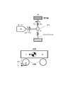
図1は、一実施の形態における電動車両の制御装置を備えた電気自動車の主要構成を示すブロック図である。本発明の電動車両の制御装置は、車両の駆動源の一部または全部として電動モータを備え、電動モータの駆動力により走行可能な電動車両に適用可能である。電動車両には、電気自動車だけでなく、ハイブリッド自動車や燃料電池自動車も含まれる。特に、本実施形態における電動車両の制御装置は、アクセルペダルの操作のみで車両の加減速や停止を制御することができる車両に適用することができる。この車両では、ドライバは、加速時にアクセルペダルを踏み込み、減速時や停止時には、踏み込んでいるアクセルペダルの踏み込み量を減らすか、または、アクセルペダルの踏み込み量をゼロとする。 FIG. 1 is a block diagram illustrating a main configuration of an electric vehicle including an electric vehicle control device according to an embodiment. The control device for an electric vehicle according to the present invention is applicable to an electric vehicle that includes an electric motor as a part or all of a drive source of the vehicle and can travel by the driving force of the electric motor. Electric vehicles include not only electric vehicles but also hybrid vehicles and fuel cell vehicles. In particular, the control device for an electric vehicle in the present embodiment can be applied to a vehicle that can control acceleration / deceleration and stop of the vehicle only by operating an accelerator pedal. In this vehicle, the driver depresses the accelerator pedal at the time of acceleration and reduces the amount of depression of the accelerator pedal at the time of deceleration or stop, or sets the depression amount of the accelerator pedal to zero.
モータコントローラ2は、車速V、アクセル開度AP、電動モータ(三相交流モータ)4の回転子位相α、電動モータ4の電流iu、iv、iw等の車両状態を示す信号をデジタル信号として入力し、入力された信号に基づいて、電動モータ4を制御するためのPWM信号を生成する。また、モータコントローラ2は、生成したPWM信号に応じてインバータ3の駆動信号を生成する。
The motor controller 2 inputs signals indicating the vehicle state such as the vehicle speed V, the accelerator opening AP, the rotor phase α of the electric motor (three-phase AC motor) 4, the currents iu, iv, iw of the electric motor 4 as digital signals. Then, a PWM signal for controlling the electric motor 4 is generated based on the input signal. The motor controller 2 generates a drive signal for the
インバータ3は、例えば、各相ごとに2個のスイッチング素子(例えば、IGBTやMOS−FET等のパワー半導体素子)を備え、駆動信号に応じてスイッチング素子をオン/オフすることにより、バッテリ1から供給される直流の電流を交流に変換し、電動モータ4に所望の電流を流す。
The
電動モータ4は、インバータ3から供給される交流電流により駆動力を発生し、減速機5およびドライブシャフト8を介して、左右の駆動輪9a、9bに駆動力を伝達する。また、電動モータ4は、車両の走行時に駆動輪9a、9bに連れ回されて回転するときに、回生駆動力を発生させることで、車両の運動エネルギーを電気エネルギーとして回収する。この場合、インバータ3は、電動モータ4の回生運転時に発生する交流電流を直流電流に変換して、バッテリ1に供給する。
The electric motor 4 generates a driving force by the alternating current supplied from the
電流センサ7は、電動モータ4に流れる3相交流電流iu、iv、iwを検出する。ただし、3相交流電流iu、iv、iwの和は0であるため、任意の2相の電流を検出して、残りの1相の電流は演算により求めてもよい。
The
回転センサ6は、例えば、レゾルバやエンコーダであり、電動モータ4の回転子位相αを検出する。 The rotation sensor 6 is, for example, a resolver or an encoder, and detects the rotor phase α of the electric motor 4.
図2は、モータコントローラ2によって行われるモータ電流制御の処理の流れを示すフローチャートである。 FIG. 2 is a flowchart showing a flow of processing of motor current control performed by the motor controller 2.
ステップS201では、車両状態を示す信号を入力する。ここでは、車速V(km/h)、アクセル開度AP(%)、電動モータ4の回転子位相α(rad)、電動モータ4の回転速度Nm(rpm)、電動モータ4に流れる三相交流電流iu、iv、iw、バッテリ1とインバータ3間の直流電圧値Vdc(V)を入力する。
In step S201, a signal indicating the vehicle state is input. Here, the vehicle speed V (km / h), the accelerator opening AP (%), the rotor phase α (rad) of the electric motor 4, the rotational speed Nm (rpm) of the electric motor 4, and the three-phase AC flowing through the electric motor 4 Currents iu, iv, iw, and a DC voltage value Vdc (V) between the
車速V(km/h)は、図示しない車速センサや、他のコントローラより通信にて取得する。または、回転子機械角速度ωmにタイヤ動半径Rを乗算し、ファイナルギアのギア比で除算することにより車速v(m/s)を求め、3600/1000を乗算することにより単位変換して、車速V(km/h)を求める。 The vehicle speed V (km / h) is acquired by communication from a vehicle speed sensor (not shown) or another controller. Alternatively, the rotor mechanical angular speed ωm is multiplied by the tire dynamic radius R, and the vehicle speed v (m / s) is obtained by dividing by the gear ratio of the final gear, and unit conversion is performed by multiplying by 3600/1000 to obtain the vehicle speed. V (km / h) is obtained.
アクセル開度AP(%)は、図示しないアクセル開度センサから取得するか、図示しない車両コントローラ等の他のコントローラから通信にて取得する。 The accelerator opening AP (%) is acquired from an accelerator opening sensor (not shown), or is acquired by communication from another controller such as a vehicle controller (not shown).
電動モータ4の回転子位相α(rad)は、回転センサ6から取得する。電動モータ4の回転速度Nm(rpm)は、回転子角速度ω(電気角)を電動モータ4の極対数pで除算して、電動モータ4の機械的な角速度であるモータ回転速度ωm(rad/s)を求め、求めたモータ回転速度ωmに60/(2π)を乗算することによって求める。回転子角速度ωは、回転子位相αを微分することによって求める。 The rotor phase α (rad) of the electric motor 4 is acquired from the rotation sensor 6. The rotational speed Nm (rpm) of the electric motor 4 is obtained by dividing the rotor angular speed ω (electrical angle) by the pole pair number p of the electric motor 4 to obtain a motor rotational speed ωm (rad / s) is obtained by multiplying the obtained motor rotational speed ωm by 60 / (2π). The rotor angular velocity ω is obtained by differentiating the rotor phase α.
電動モータ4に流れる電流iu、iv、iw(A)は、電流センサ7から取得する。
Currents iu, iv, iw (A) flowing through the electric motor 4 are acquired from the
直流電圧値Vdc(V)は、バッテリ1とインバータ3間の直流電源ラインに設けられた電圧センサ(不図示)、または、バッテリコントローラ(不図示)から送信される電源電圧値から求める。
The DC voltage value Vdc (V) is obtained from a power supply voltage value transmitted from a voltage sensor (not shown) provided on a DC power supply line between the
ステップS202では、第1のトルク目標値Tm1*を設定する。具体的には、まず始めに、ステップS201で入力されたアクセル開度APおよびモータ回転速度ωmに基づいて、図3に示すアクセル開度−トルクテーブルを参照することにより、トルクテーブル目標値(基本トルク目標値)Tm0*を設定する。続いて、後述する外乱トルク推定値Tdを求めるとともに、外乱トルク推定値Tdに基づいて、外乱補正トルクTd*を求める。そして、トルクテーブル目標値Tm0*と外乱補正トルクTd*とを加算することによって、第1のトルク目標値Tm1*を設定する。In step S202, a first torque target value Tm1 * is set. Specifically, first, based on the accelerator opening AP and the motor rotational speed ωm input in step S201, the accelerator opening-torque table shown in FIG. Torque target value) Tm0 * is set. Subsequently, a disturbance torque estimated value Td described later is obtained, and a disturbance correction torque Td * is obtained based on the disturbance torque estimated value Td. Then, the first torque target value Tm1 * is set by adding the torque table target value Tm0 * and the disturbance correction torque Td * .
ステップS203では、電動車両が停止するように制御する停止制御処理を行う。具体的には、電動車両の停車間際を判断し、停車間際以前は、ステップS202で算出した第1のトルク目標値Tm1*をモータトルク指令値Tm*に設定し、停車間際以降は、モータ回転速度の低下とともに外乱トルク推定値Tdに収束する第2のトルク目標値Tm2*をモータトルク指令値Tm*に設定する。この第2のトルク目標値Tm2*は、登坂路では正トルク、降坂路では負トルク、平坦路では概ねゼロである。これにより、後述するように、路面の勾配に関わらず、停車状態を維持することができる。停止制御処理の詳細については、後述する。In step S203, stop control processing for controlling the electric vehicle to stop is performed. Specifically, the stop time of the electric vehicle is determined. Before the stop, the first torque target value Tm1 * calculated in step S202 is set to the motor torque command value Tm *. The second torque target value Tm2 * that converges to the disturbance torque estimated value Td as the speed decreases is set as the motor torque command value Tm * . The second torque target value Tm2 * is positive torque on an uphill road, negative torque on a downhill road, and almost zero on a flat road. Thereby, the stop state can be maintained regardless of the gradient of the road surface, as will be described later. Details of the stop control process will be described later.
ステップS204では、ステップS203で算出したモータトルク目標値Tm*、モータ回転速度ωmおよび直流電圧値Vdcに基づいて、d軸電流目標値id*、q軸電流目標値iq*を求める。例えば、トルク指令値、モータ回転速度、および直流電圧値と、d軸電流目標値およびq軸電流目標値との関係を定めたテーブルを予め用意しておいて、このテーブルを参照することにより、d軸電流目標値id*、q軸電流目標値iq*を求める。In step S204, the d-axis current target value id * and the q-axis current target value iq * are obtained based on the motor torque target value Tm * , the motor rotation speed ωm, and the DC voltage value Vdc calculated in step S203. For example, by preparing in advance a table that defines the relationship between the torque command value, the motor rotation speed, and the DC voltage value, the d-axis current target value, and the q-axis current target value, The d-axis current target value id * and the q-axis current target value iq * are obtained.
ステップS205では、d軸電流idおよびq軸電流iqをそれぞれ、ステップS204で求めたd軸電流目標値id*およびq軸電流目標値iq*と一致させるための電流制御を行う。このため、まず初めに、ステップS201で入力された三相交流電流値iu、iv、iwと、電動モータ4の回転子位相αとに基づいて、d軸電流idおよびq軸電流iqを求める。続いて、d軸、q軸電流指令値id*、iq*と、d軸、q軸電流id、iqとの偏差から、d軸、q軸電圧指令値vd、vqを算出する。なお、算出したd軸、q軸電圧指令値vd、vqに対して、d−q直交座標軸間の干渉電圧を相殺するために必要な非干渉電圧を加算するようにしてもよい。In step S205, current control is performed to match the d-axis current id and the q-axis current iq with the d-axis current target value id * and the q-axis current target value iq * obtained in step S204, respectively. For this reason, first, the d-axis current id and the q-axis current iq are obtained based on the three-phase AC current values iu, iv, iw input in step S201 and the rotor phase α of the electric motor 4. Subsequently, d-axis and q-axis voltage command values vd and vq are calculated from a deviation between the d-axis and q-axis current command values id * and iq * and the d-axis and q-axis current id and iq. In addition, you may make it add the non-interference voltage required in order to cancel the interference voltage between dq orthogonal coordinate axes with respect to the calculated d-axis and q-axis voltage command values vd and vq.
次に、d軸、q軸電圧指令値vd、vqと、電動モータ4の回転子位相αから、三相交流電圧指令値vu、vv、vwを求める。そして、求めた三相交流電圧指令値vu、vv、vwと直流電圧値Vdcから、PWM信号tu(%)、tv(%)、tw(%)を求める。このようにして求めたPWM信号tu、tv、twにより、インバータ3のスイッチング素子を開閉することによって、電動モータ4をトルク指令値Tm*で指示された所望のトルクで駆動することができる。Next, three-phase AC voltage command values vu, vv, vw are obtained from the d-axis and q-axis voltage command values vd, vq and the rotor phase α of the electric motor 4. Then, PWM signals tu (%), tv (%), and tw (%) are obtained from the obtained three-phase AC voltage command values vu, vv, and vw and the DC voltage value Vdc. The electric motor 4 can be driven with a desired torque indicated by the torque command value Tm * by opening and closing the switching element of the
図2のステップS202で行われる処理、すなわち、第1のトルク目標値Tm1*を設定する方法の詳細を、図4を用いて説明する。Details of the process performed in step S202 of FIG. 2, that is, the method of setting the first torque target value Tm1 * will be described with reference to FIG.
トルクテーブル目標値設定器401は、アクセル開度APおよびモータ回転速度ωmに基づいて、図3に示すアクセル開度−トルクテーブルを参照することにより、トルクテーブル目標値Tm0*を設定する。The torque table
外乱トルク推定器402は、モータトルク指令値Tm*およびモータ回転速度ωmに基づいて、外乱トルク推定値Tdを求める。The
図5は、外乱トルク推定器402の詳細な構成を示すブロック図である。外乱トルク推定器402は、制御ブロック501と、制御ブロック502と、減算器503と、制御ブロック504とを備える。
FIG. 5 is a block diagram showing a detailed configuration of the
制御ブロック501は、H(s)/Gp(s)なる伝達特性を有するフィルタとしての機能を担っており、モータ回転速度ωmを入力してフィルタリング処理を行うことにより、第1のモータトルク推定値を算出する。Gp(s)は、モータトルクTmからモータ回転速度ωmまでの伝達特性であり、詳細については後述する。H(s)は、分母次数と分子次数との差分が、モデルGr(s)の分母次数と分子次数との差分以上となる伝達特性を有するローパスフィルタである。
The
制御ブロック502は、H(s)なる伝達特性を有するローパスフィルタとしての機能を担っており、モータトルク指令値Tm*を入力してフィルタリング処理を行うことにより、第2のモータトルク推定値を算出する。The
減算器503は、第2のモータトルク推定値から第1のモータトルク推定値を減算することによって、外乱トルク推定値Tdを算出する。
The
本実施形態では、第2のモータトルク推定値と第1のモータトルク推定値との偏差に対して、制御ブロック504によりフィルタリング処理を施すことにより、外乱トルク推定値Tdを算出する。制御ブロック504は、Hz(s)なる伝達特性を有するフィルタとしての機能を担っており、第2のモータトルク推定値と第1のモータトルク推定値との偏差を入力してフィルタリング処理を行うことにより、外乱トルク推定値Tdを算出する。Hz(s)の詳細については、後述する。
In the present embodiment, the disturbance torque estimated value Td is calculated by filtering the deviation between the second motor torque estimated value and the first motor torque estimated value by the
図4の外乱補正トルク設定器403は、外乱トルク推定器402によって算出された外乱トルク推定値Tdに基づいて、外乱補正トルクTd*を求める。The disturbance correction
図6は、外乱補正トルク設定器403の詳細な構成を示すブロック図である。外乱補正トルク設定器403は、登坂補正トルク算出器601と、急登坂補正処理器602と、降坂補正トルク算出器603と、急降坂補正処理器604と、勾配判定器605と、速度補正トルク設定処理器606とを備える。
FIG. 6 is a block diagram showing a detailed configuration of the disturbance correction
登坂補正トルク算出器601は、外乱トルク推定値Tdに所定の補正ゲインKupを乗算することによって、登坂補正トルクTd1を算出する。
The uphill
急登坂補正処理器602は、図3に示すアクセル開度−トルクテーブルの「アクセル開度=0/4(全閉)」時のモータトルク指令値に基づいて、登坂補正トルクTd1に対してリミッタ処理を施し、リミッタ処理後の登坂リミッタトルクTd2を算出する。
The steep
降坂補正トルク算出器603は、外乱トルク推定値Tdに所定の降坂補正ゲインKdownを乗算することによって、降坂補正トルクTd3を算出する。
The downhill
急降坂補正処理器604は、急降坂のように、外乱トルク推定値Tdの絶対値が所定値以上の場合に、車両の減速度を一定とする降坂リミッタトルクTd4を算出する。具体的には、急降坂における車両の減速度を規定し、図3に示すアクセル開度−トルクテーブルの「アクセル開度=0/4(全閉)」時のモータトルク指令値と外乱トルク推定値Tdより、必要となる降坂リミッタトルクTd4を算出する。
The sudden
勾配判定器605は、外乱トルク推定値Tdの符号に基づいて路面の勾配を判定し、登坂(外乱トルク推定値Td>0)では登坂リミッタトルクTd2を勾配補正トルクTd5に設定し、降坂(外乱トルク推定値Td<0)では降坂リミッタトルクTd4を勾配補正トルクTd5に設定する。
The
なお、外乱トルク推定値Tdと勾配補正トルクTd5との関係を定めたテーブルを予め用意しておき、外乱トルク推定値Tdに基づいて、テーブルを参照することにより、勾配補正トルクTd5を求めるようにしてもよい。 A table that defines the relationship between the disturbance torque estimated value Td and the gradient correction torque Td5 is prepared in advance, and the gradient correction torque Td5 is obtained by referring to the table based on the disturbance torque estimated value Td. May be.
図7は、外乱トルク推定値Tdと勾配補正トルクTd5との関係を定めたテーブルの一例を示す図である。路面が急登坂の場合、すなわち、外乱トルク推定値Tdが所定値Td1以上の場合は、勾配補正トルクTd5を所定の上限値に設定する。また、急登坂ではない登坂路の場合、すなわち、外乱トルク推定値Tdが0より大きく所定値Td1未満の場合には、外乱トルク推定値Tdが小さくなるほど、勾配補正トルクTd5を小さい値(ただし、Td5>0)に設定する。路面が急降坂ではない降坂路の場合、すなわち、外乱トルク推定値Tdが0より小さく所定値Td2より大きい場合には、外乱トルク推定値Tdが小さくなるほど勾配補正トルクを小さい値(ただし、Td5<0)に設定する。路面が急降坂の場合、すなわち、外乱トルク推定値Tdが所定値Td2以下の場合には、外乱トルク推定値Tdが小さくなるほど勾配補正トルクを小さい値(ただし、Td5<0)に設定する。ただし、急降坂の場合、急降坂ではない降坂路に比べて、外乱トルク推定値が小さくなるほど、勾配補正トルクTd5がより小さい値となるようにする。 FIG. 7 is a diagram showing an example of a table defining the relationship between the disturbance torque estimated value Td and the gradient correction torque Td5. When the road surface is a steep climb, that is, when the disturbance torque estimated value Td is equal to or greater than the predetermined value Td1, the gradient correction torque Td5 is set to a predetermined upper limit value. Further, in the case of an uphill road that is not a steep climb, that is, when the estimated disturbance torque value Td is greater than 0 and less than the predetermined value Td1, the gradient correction torque Td5 decreases as the disturbance torque estimate value Td decreases (however, Td5> 0). When the road surface is a downhill road that is not a steep downhill, that is, when the estimated disturbance torque value Td is smaller than 0 and larger than the predetermined value Td2, the gradient correction torque becomes smaller as the estimated disturbance torque value Td becomes smaller (however, Td5 Set to <0). When the road surface is a steep descent, that is, when the estimated disturbance torque value Td is equal to or less than the predetermined value Td2, the gradient correction torque is set to a smaller value (however, Td5 <0) as the estimated disturbance torque value Td becomes smaller. However, in the case of a steeply descending slope, the gradient correction torque Td5 is set to a smaller value as the estimated disturbance torque is smaller than that of a descending slope that is not a steeply descending slope.
図6の速度補正トルク設定処理器606は、モータ回転速度ωmに基づいて、モータ回転速度ωmと速度補正ゲインKωとの関係を定めたテーブルを参照することにより、速度補正ゲインKωを求め、勾配補正トルクTd5に速度補正ゲインKωを乗算することにより、外乱補正トルクTd*を算出する。The speed correction
図8は、モータ回転速度ωmと速度補正ゲインKωとの関係を定めたテーブルの一例である。モータ回転速度ωmが所定回転速度ωm1より低い低速域では、速度補正ゲインKωを1とし、モータ回転速度ωmが所定回転速度ωm2(ω1<ω2)以上の高速域では、速度補正ゲインKωを0とする。これにより、低速域では、勾配補正トルクTd5が外乱補正トルクTd*として出力され、高速域では、外乱補正トルクTd*は0となる。また、モータ回転速度ωmが所定回転速度ωm1以上であり、かつ、所定回転速度ωm2未満の中速域では、モータ回転速度ωmが高くなるにつれて値が小さくなるように、速度補正ゲインを設定する。FIG. 8 is an example of a table that defines the relationship between the motor rotation speed ωm and the speed correction gain Kω. When the motor rotational speed ωm is lower than the predetermined rotational speed ωm1, the speed correction gain Kω is 1, and when the motor rotational speed ωm is the predetermined rotational speed ωm2 (ω1 <ω2) or higher, the speed correction gain Kω is 0. To do. As a result, the gradient correction torque Td5 is output as the disturbance correction torque Td * in the low speed range, and the disturbance correction torque Td * is 0 in the high speed range. Further, the speed correction gain is set so that the value decreases as the motor rotational speed ωm increases in the medium speed range where the motor rotational speed ωm is equal to or higher than the predetermined rotational speed ωm1 and less than the predetermined rotational speed ωm2.
図4に戻って説明を続ける。加算器404は、トルクテーブル目標値設定器401によって設定されたトルクテーブル目標値Tm0*と、外乱補正トルク設定器403によって設定された外乱補正トルクTd*とを加算することにより、第1のトルク目標値Tm1*を算出する。Returning to FIG. 4, the description will be continued. The
上述した方法によって第1のトルク目標値Tm1*を算出することにより、停車間際と判断するまでの減速度を調整することができるので、減速中の減速度から、モータトルク指令値Tm*を外乱トルク推定値Tdに収束させて停車させた際の減速度までの変化量を抑えることができ、ドライブフィーリングを向上させることができる。By calculating the first torque target value Tm1 * by the above-described method, the deceleration until it is determined that the vehicle is about to stop can be adjusted. Therefore, the motor torque command value Tm * is disturbed from the deceleration during deceleration. The amount of change until deceleration when the vehicle is stopped by converging on the estimated torque value Td can be suppressed, and drive feeling can be improved.
続いて、図2のステップS203で行われる停止制御処理について説明する前に、本実施形態における電動車両の制御装置において、モータトルクTmからモータ回転速度ωmまでの伝達特性Gp(s)について説明する。 Subsequently, before describing the stop control process performed in step S203 of FIG. 2, the transfer characteristic Gp (s) from the motor torque Tm to the motor rotation speed ωm will be described in the control device for the electric vehicle in the present embodiment. .
図9は、車両の駆動力伝達系をモデル化した図であり、同図における各パラメータは、以下に示すとおりである。
Jm:電動モータのイナーシャ
Jw:駆動輪のイナーシャ
M:車両の重量
Kd:駆動系の捻り剛性
Kt:タイヤと路面の摩擦に関する係数
N:オーバーオールギヤ比
r:タイヤの荷重半径
ωm:電動モータの角速度
Tm:トルク目標値
Td:駆動輪のトルク
F:車両に加えられる力
V:車両の速度
ωw:駆動輪の角速度FIG. 9 is a diagram modeling a driving force transmission system of a vehicle, and each parameter in the figure is as shown below.
J m : Inertia of electric motor J w : Inertia of drive wheel M: Vehicle weight K d : Torsional rigidity of drive system K t : Coefficient related to friction between tire and road surface N: Overall gear ratio r: Tire load radius ω m : the electric motor angular velocity T m: torque target value T d: a torque of the drive wheel F: force applied to the vehicle V: vehicle speed omega w: angular velocity of the drive wheel
そして、図9より、以下の運動方程式を導くことができる。ただし、式(1)〜(3)中の符号の右上に付されているアスタリスク(*)は、時間微分を表している。

式(1)〜(5)で示す運動方程式に基づいて、電動モータ4のトルク目標値Tmからモータ回転速度ωmまでの伝達特性Gp(s)を求めると、次式(6)で表される。
ただし、式(6)中の各パラメータは、次式(7)で表される。
式(6)に示す伝達関数の極と零点を調べると、次式(8)の伝達関数に近似することができ、1つの極と1つの零点は極めて近い値を示す。これは、次式(8)のαとβが極めて近い値を示すことに相当する。
従って、式(8)における極零相殺(α=βと近似する)を行うことにより、次式(9)に示すように、Gp(s)は、(2次)/(3次)の伝達特性を構成する。
続いて、図2のステップS203で行われる停止制御処理の詳細について説明する。図10は、停止制御処理を実現するためのブロック図である。 Next, details of the stop control process performed in step S203 of FIG. 2 will be described. FIG. 10 is a block diagram for realizing the stop control process.
モータ回転速度F/Bトルク設定器1001は、検出されたモータ回転速度ωmに基づいて、モータ回転速度フィードバックトルク(以下、モータ回転速度F/Bトルクと呼ぶ)Tωを算出する。
The motor rotation speed F /
図11は、検出されたモータ回転速度ωmに基づいて、モータ回転速度F/BトルクTωを算出する方法を説明するための図である。モータ回転速度F/Bトルク設定器1001は、乗算器1101を備え、モータ回転速度ωmにゲインKvrefを乗算することにより、モータ回転速度F/BトルクTωを算出する。ただし、Kvrefは、電動車両の停止間際に電動車両を停止させるのに必要な負(マイナス)の値であり、例えば、実験データ等により適宜設定される。モータ回転速度F/BトルクTωは、モータ回転速度ωmが大きいほど、大きい回生制動力が得られるトルクとして設定される。
FIG. 11 is a diagram for explaining a method of calculating the motor rotation speed F / B torque Tω based on the detected motor rotation speed ωm. The motor rotation speed F /
なお、モータ回転速度F/Bトルク設定器1001は、モータ回転速度ωmにゲインKvrefを乗算することにより、モータ回転速度F/BトルクTωを算出するものとして説明したが、モータ回転速度ωmに対する回生トルクを定めた回生トルクテーブルや、モータ回転速度ωmの減衰率を予め記憶した減衰率テーブル等を用いて、モータ回転速度F/BトルクTωを算出してもよい。
The motor rotation speed F /
図10に戻って説明を続ける。外乱トルク推定器1002は、検出されたモータ回転速度ωmとモータトルク指令値Tm*に基づいて、外乱トルク推定値Tdを算出する。外乱トルク推定器1002の構成は、図4の外乱トルク推定器402の構成、すなわち、図5に示す構成と同じである。Returning to FIG. The
ここで、図5の制御ブロック504の伝達特性Hz(s)について説明する。式(9)を書き換えると、次式(10)が得られる。ただし、式(10)中のζz、ωz、ζp、ωpはそれぞれ、式(11)で表される。
以上より、Hz(s)を次式(12)で表す。ただし、ζc>ζzとする。また、ギアのバックラッシュを伴う減速シーンで振動抑制効果を高めるために、ζc>1とする。
なお、本実施形態では、外乱トルクは、図5に示す通り、外乱オブザーバにより推定するが、車両前後Gセンサ等の計測器を使って推定してもよい。 In this embodiment, the disturbance torque is estimated by a disturbance observer as shown in FIG. 5, but may be estimated by using a measuring instrument such as a vehicle front-rear G sensor.
ここで、外乱としては、空気抵抗、乗員数や積載量に起因する車両質量の変動によるモデル化誤差、タイヤの転がり抵抗、路面の勾配抵抗等が考えられるが、停車間際で支配的となる外乱要因は勾配抵抗である。外乱要因は運転条件により異なるが、外乱トルク推定器402および外乱トルク推定器1002は、モータトルク指令値Tm*と、モータ回転速度ωmと、車両モデルGp(s)とに基づいて、外乱トルク推定値Tdを算出するので、上述した外乱要因を一括して推定することができる。これにより、いかなる運転条件においても、減速からの滑らかな停車を実現することができる。Here, disturbances include air resistance, modeling errors due to vehicle mass fluctuations due to the number of passengers and loading capacity, tire rolling resistance, road surface gradient resistance, etc., but disturbances that are dominant immediately before stopping The factor is gradient resistance. Although the disturbance factor varies depending on the driving conditions, the
図10に戻って説明を続ける。加算器1003は、モータ回転速度F/Bトルク設定器1001によって算出されたモータ回転速度F/BトルクTωと、外乱トルク推定器1002によって算出された外乱トルク推定値Tdとを加算することによって、第2のトルク目標値Tm2*を算出する。Returning to FIG. The
トルク比較器1004は、第1のトルク目標値Tm1*と第2のトルク目標値Tm2*の大きさを比較し、値が大きい方のトルク目標値をモータトルク指令値Tm*に設定する。車両の走行中、第2のトルク目標値Tm2*は第1のトルク目標値Tm1*よりも小さく、車両が減速して停車間際(車速が所定車速以下)になると、第1のトルク目標値Tm1*よりも大きくなる。従って、トルク比較器1004は、第1のトルク目標値Tm1*が第2のトルク目標値Tm2*より大きければ、停車間際以前と判断して、モータトルク指令値Tm*を第1のトルク目標値Tm1*に設定する。また、トルク比較器1004は、第2のトルク目標値Tm2*が第1のトルク目標値Tm1*より大きくなると、車両が停車間際と判断して、モータトルク指令値Tm*を第1のトルク目標値Tm1*から第2のトルク目標値Tm2*に切り替える。なお、停車状態を維持するため、第2のトルク目標値Tm2*は、登坂路では正トルク、降坂路では負トルク、平坦路では概ねゼロに収束する。The
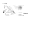
図12は、登坂路において電動車両を停止させる停止制御の制御結果を示す図である。図12(a)は、第1のトルク目標値Tm1*を算出する際に、トルクテーブル目標値Tm0*を補正しない(図4の外乱トルク推定器402および外乱補正トルク設定器403が無い)構成の比較例の制御結果、図12(b)は、本実施形態における電動車両の制御装置による制御結果であり、上から順に、車輪速度、減速度、モータトルク指令値を表している。FIG. 12 is a diagram illustrating a control result of stop control for stopping the electric vehicle on the uphill road. FIG. 12A shows a configuration in which the torque table target value Tm0 * is not corrected when the first torque target value Tm1 * is calculated (the
図12(a)において、時刻t3までは、アクセル開度とモータ回転速度に基づいて算出されるトルクテーブル目標値Tm0*に基づいて減速する。In FIG. 12A, until time t3, the vehicle decelerates based on the torque table target value Tm0 * calculated based on the accelerator opening and the motor rotation speed.
時刻t3では、路面の勾配によらず、モータ回転速度ωmが所定回転速度まで低下したことにより停車間際と判断して、モータトルク指令値Tm*を第1のトルク目標値Tm1*から第2のトルク目標値Tm2*に切り替える。これにより、時刻t3〜t5では、モータトルク指令値Tm*が外乱トルク推定値Tdと一致するように急に変化する。急なモータトルク指令値Tm*の変化により、ドライバは、モータトルク指令値の切り替えのタイミングでのトルク段差や、急なトルク変化によるショックを感じる。すなわち、路面の勾配によらず、同じ回転速度(車速)でモータトルク指令値を切り替えるので、登坂路では、モータトルク指令値の変化が大きくなり、ドライバは急なトルク変化によるショックを感じやすくなる。At time t3, the motor torque command value Tm * is determined from the first torque target value Tm1 * to the second torque because the motor rotational speed ωm has been reduced to the predetermined rotational speed and is determined to be about to stop regardless of the road surface gradient. Switch to torque target value Tm2 * . As a result, at times t3 to t5, the motor torque command value Tm * changes suddenly so as to coincide with the disturbance torque estimated value Td. Due to a sudden change in the motor torque command value Tm * , the driver feels a torque step at the timing of switching the motor torque command value or a shock due to a sudden torque change. That is, since the motor torque command value is switched at the same rotational speed (vehicle speed) regardless of the road surface gradient, the change in the motor torque command value becomes large on the uphill road, and the driver can easily feel a shock due to a sudden torque change. .
時刻t5以後は、車輪速度が0となり、停車状態を維持する。 After time t5, the wheel speed becomes 0, and the stopped state is maintained.
図12(b)において、時刻t0までは図8の高速域であり、図4の外乱補正トルク設定器403によって算出される外乱補正トルクTd*は0である。従って、時刻t0までは、トルクテーブル目標値設定器401から出力されるトルクテーブル目標値Tm0*に基づいて減速する。In FIG. 12B, the time until the time t0 is the high speed range of FIG. 8, and the disturbance correction torque Td * calculated by the disturbance correction
時刻t0〜t1の区間は、図8の中速域である。この区間では、外乱トルク推定値Tdに基づいて求められた勾配補正トルクTd5に、モータ回転速度ωmに応じた速度補正ゲインKωを乗算することにより、外乱補正トルクTd*を算出し(図6の速度補正トルク設定処理器606)、トルクテーブル目標値設定器401から出力されるトルクテーブル目標値Tm0*と外乱補正トルクTd*とを加算することにより、第1のトルク目標値Tm1*を算出する。そして、算出した第1のトルク目標値Tm1*に基づいて減速する。The section from time t0 to t1 is the middle speed range in FIG. In this section, the disturbance correction torque Td * is calculated by multiplying the gradient correction torque Td5 obtained based on the disturbance torque estimated value Td by the speed correction gain Kω corresponding to the motor rotation speed ωm (FIG. 6). The first torque target value Tm1 * is calculated by adding the torque table target value Tm0 * and the disturbance correction torque Td * output from the speed correction torque setting processor 606) and the torque table target
時刻t1以降の区間は、図8の低速域である。この区間では、図4の外乱補正トルク設定器403によって算出される外乱補正トルクTd*は、外乱トルク推定器402によって求められる外乱トルク推定値Tdと同じであり、トルクテーブル目標値設定器401から出力されるトルクテーブル目標値Tm0*と外乱補正トルクTd*とを加算することにより、第1のトルク目標値Tm1*を算出する。そして、算出した第1のトルク目標値Tm1*に基づいて減速する。The section after time t1 is the low speed region of FIG. In this section, the disturbance correction torque Td * calculated by the disturbance correction
時刻t2では、第2のトルク目標値Tm2*が第1のトルク目標値Tm1*より大きくなり、車両が停車間際と判断して、モータトルク指令値Tm*を第1のトルク目標値Tm1*から第2のトルク目標値Tm2*に切り替える。この切り替えのタイミングは、路面の勾配によって異なる。これにより、時刻t2〜t5では、モータトルク指令値Tm*が外乱トルク推定値Tdに収束するように滑らかに変化する。At time t2, the second torque target value Tm2 * is greater than the first torque target value Tm1 *, and it is determined that the vehicle is about to stop, and the motor torque command value Tm * is determined from the first torque target value Tm1 *. Switch to the second torque target value Tm2 * . The timing of this switching varies depending on the road surface gradient. Thus, at times t2 to t5, the motor torque command value Tm * changes smoothly so as to converge to the disturbance torque estimated value Td.
時刻t5では、モータトルク指令値Tm*は外乱トルク推定値Tdに漸近的に収束し、モータ回転速度ωmはゼロに漸近的に収束する。これにより、加速度振動の無い滑らかな停車が可能となる。時刻t5以降は、停車状態を保持する。At time t5, the motor torque command value Tm * converges asymptotically to the disturbance torque estimated value Td, and the motor rotational speed ωm converges asymptotically to zero. Thereby, a smooth stop without acceleration vibration is possible. After time t5, the stopped state is maintained.
すなわち、本実施形態における電動車両の制御装置によれば、外乱トルク推定値に基づいて外乱補正トルクTd*を算出するとともに、算出した外乱補正トルクTd*も考慮して、車両が停止間際であるか否かの判断を行って、モータトルク指令値Tm*を第1のトルク目標値Tm1*から第2のトルク目標値Tm2*に切り替えるので、登坂路においても平坦路と同等の滑らかな減速および停車を実現することができる。That is, according to the control apparatus for an electric vehicle in the present embodiment, the disturbance correction torque Td * is calculated based on the estimated disturbance torque value, and the vehicle is about to stop in consideration of the calculated disturbance correction torque Td *. And the motor torque command value Tm * is switched from the first torque target value Tm1 * to the second torque target value Tm2 * . Therefore, smooth deceleration equivalent to a flat road on the uphill road and A stop can be realized.
図13は、降坂路において電動車両を停止させる停止制御の制御結果を示す図である。図13(a)は、第1のトルク目標値Tm1*を算出する際に、トルクテーブル目標値Tm0*を補正しない(図4の外乱トルク推定器402および外乱補正トルク設定器403が無い)構成の比較例の制御結果、図13(b)は、本実施形態における電動車両の制御装置による制御結果であり、上から順に、車輪速度、減速度、モータトルク指令値を表している。FIG. 13 is a diagram illustrating a control result of stop control for stopping the electric vehicle on the downhill road. FIG. 13A shows a configuration in which the torque table target value Tm0 * is not corrected when the first torque target value Tm1 * is calculated (the
図13(a)において、時刻t3までは、アクセル開度とモータ回転速度に基づいて算出されるトルクテーブル目標値Tm0*に基づいて減速する。In FIG. 13A, the vehicle is decelerated based on the torque table target value Tm0 * calculated based on the accelerator opening and the motor rotation speed until time t3.
時刻t3では、路面の勾配によらず、モータ回転速度ωmが所定回転速度まで低下することによって停車間際と判断して、モータトルク指令値Tm*を第1のトルク目標値Tm1*から第2のトルク目標値Tm2*に切り替える。これにより、時刻t3〜t6では、緩慢なトルク変化によって、停車までの時間、停止距離が長くなり、ドライブフィーリングが悪化して、滑らかな停車を損なうことになる。すなわち、路面の勾配によらず、同じ回転速度(車速)でモータトルク指令値を切り替える比較例の構成では、降坂路では、モータトルク指令値Tm*が外乱トルク推定値Tdに収束するまでの時間が長くなり、ドライブフィーリングが悪化する。At time t3, regardless of the road surface gradient, the motor rotational speed ωm is reduced to a predetermined rotational speed, so that it is determined that the vehicle is about to stop, and the motor torque command value Tm * is changed from the first torque target value Tm1 * to the second time. Switch to torque target value Tm2 * . As a result, at times t3 to t6, due to a slow torque change, the time to stop and the stop distance become longer, the drive feeling deteriorates, and the smooth stop is impaired. That is, in the configuration of the comparative example in which the motor torque command value is switched at the same rotational speed (vehicle speed) regardless of the road surface gradient, on the downhill road, the time until the motor torque command value Tm * converges to the disturbance torque estimated value Td. Becomes longer and drive feeling worsens.
時刻t6以後は、車輪速度が0となり、停車状態を維持する。 After time t6, the wheel speed becomes 0, and the vehicle stops.
図13(b)において、時刻t0までは、図8の高速域であり、図4の外乱補正トルク設定器403によって算出される外乱補正トルクTd*は0である。従って、時刻t0までは、トルクテーブル目標値設定器401から出力されるトルクテーブル目標値Tm0*に基づいて減速する。In FIG. 13B, until the time t0, the high speed region of FIG. 8 is obtained, and the disturbance correction torque Td * calculated by the disturbance correction
時刻t0〜t1の区間は、図8の中速域である。この区間では、外乱トルク推定値Tdに基づいて求められた勾配補正トルクTd5に、モータ回転速度ωmに応じた速度補正ゲインKωを乗算することにより、外乱補正トルクTd*を算出し(図6の速度補正トルク設定処理器606)、トルクテーブル目標値設定器401から出力されるトルクテーブル目標値Tm0*と外乱補正トルクTd*とを加算することにより、第1のトルク目標値Tm1*を算出する。そして、算出した第1のトルク目標値Tm1*に基づいて減速する。The section from time t0 to t1 is the middle speed range in FIG. In this section, the disturbance correction torque Td * is calculated by multiplying the gradient correction torque Td5 obtained based on the disturbance torque estimated value Td by the speed correction gain Kω corresponding to the motor rotation speed ωm (FIG. 6). The first torque target value Tm1 * is calculated by adding the torque table target value Tm0 * and the disturbance correction torque Td * output from the speed correction torque setting processor 606) and the torque table target
時刻t1以降の区間は、図8の低速域である。この区間では、図4の外乱補正トルク設定器403によって算出される外乱補正トルクTd*は、外乱トルク推定器402によって求められる外乱トルク推定値Tdと同じであり、トルクテーブル目標値設定器401から出力されるトルクテーブル目標値Tm0*と外乱補正トルクTd*とを加算することにより、第1のトルク目標値Tm1*を算出する。そして、算出した第1のトルク目標値Tm1*に基づいて減速する。The section after time t1 is the low speed region of FIG. In this section, the disturbance correction torque Td * calculated by the disturbance correction
時刻t4では、第2のトルク目標値Tm2*が第1のトルク目標値Tm1*より大きくなり、車両が停車間際と判断して、モータトルク指令値Tm*を第1のトルク目標値Tm1*から第2のトルク目標値Tm2*に切り替える。この切り替えのタイミングは、路面の勾配によって異なる。At time t4, the second torque target value Tm2 * becomes larger than the first torque target value Tm1 *, and it is determined that the vehicle is about to stop, and the motor torque command value Tm * is changed from the first torque target value Tm1 *. Switch to the second torque target value Tm2 * . The timing of this switching varies depending on the road surface gradient.
時刻t5では、モータトルク指令値Tm*は外乱トルク推定値Tdに漸近的に収束し、モータ回転速度ωmはゼロに漸近的に収束する。これにより、加速度振動の無い滑らかな停車が可能となる。時刻t5以降は、停車状態を保持する。At time t5, the motor torque command value Tm * converges asymptotically to the disturbance torque estimated value Td, and the motor rotational speed ωm converges asymptotically to zero. Thereby, a smooth stop without acceleration vibration is possible. After time t5, the stopped state is maintained.
すなわち、本実施形態における電動車両の制御装置によれば、外乱トルク推定値に基づいて外乱補正トルクTd*を算出するとともに、算出した外乱補正トルクTd*も考慮して、車両が停止間際であるか否かの判断を行う(モータトルク指令値Tm*を第1のトルク目標値Tm1*から第2のトルク目標値Tm2*に切り替えるタイミングを決定する)ので、降坂路においても平坦路と同等の滑らかな減速および停車を実現することができる。That is, according to the control apparatus for an electric vehicle in the present embodiment, the disturbance correction torque Td * is calculated based on the estimated disturbance torque value, and the vehicle is about to stop in consideration of the calculated disturbance correction torque Td *. (The timing for switching the motor torque command value Tm * from the first torque target value Tm1 * to the second torque target value Tm2 * is determined), so that the downhill road is equivalent to the flat road. Smooth deceleration and stopping can be realized.
ここで、上述した説明では、モータ回転速度F/BトルクTωと外乱トルク推定値Tdとを加算することによって、第2のトルク目標値Tm2*を算出したが、モータ回転速度F/BトルクTωを第2のトルク目標値Tm2*として設定してもよい。図14は、モータ回転速度F/BトルクTωを第2のトルク目標値Tm2*として設定する場合において、停止制御処理を実現するためのブロック図である。図14において、図10に示す構成要素と同一の構成要素については、同一の符号を付している。この場合、第1のトルク目標値Tm1*の算出時に、外乱トルク推定値Tdはゼロとして演算する(図4)。Here, in the above description, the second torque target value Tm2 * is calculated by adding the motor rotation speed F / B torque Tω and the disturbance torque estimated value Td, but the motor rotation speed F / B torque Tω is calculated. May be set as the second torque target value Tm2 * . FIG. 14 is a block diagram for realizing the stop control process when the motor rotation speed F / B torque Tω is set as the second torque target value Tm2 * . In FIG. 14, the same components as those shown in FIG. 10 are denoted by the same reference numerals. In this case, when the first torque target value Tm1 * is calculated, the disturbance torque estimated value Td is calculated as zero (FIG. 4).
モータ回転速度F/BトルクTωを第2のトルク目標値Tm2*として設定した場合も、第2のトルク目標値Tm2*が第1のトルク目標値Tm1*より大きくなって停車間際と判断されることにより、モータトルク指令値Tm*が第1のトルク目標値Tm1*から第2のトルク目標値Tm2*に切り替わる。このとき、第2のトルク目標値Tm2*は、モータ回転速度F/BトルクTωと同一値であるため、モータ回転速度ωmの低下に応じて、モータトルク指令値Tm*はゼロに収束する。Even if you set the motor speed F / B torque Tω as the second torque target value Tm2 *, the second torque target value Tm2 * is determined to stop just before become the first torque target value Tm1 * greater As a result, the motor torque command value Tm * is switched from the first torque target value Tm1 * to the second torque target value Tm2 * . At this time, since the second torque target value Tm2 * is the same value as the motor rotation speed F / B torque Tω, the motor torque command value Tm * converges to zero as the motor rotation speed ωm decreases.
以上より、一実施の形態における電動車両の制御装置は、電動モータ4を走行駆動源とし、電動モータ4の回生制動力により減速する電動車両の制御装置であって、車両情報に基づいて、第1のトルク目標値Tm1*を算出するとともに、モータ回転速度ωmの低下とともにゼロに収束する第2のトルク目標値Tm2*を算出する。そして、車両が停車間際以前であると判定すると、第1のトルク目標値Tm1*をモータトルク指令値Tm*に設定し、車両が停車間際であると判定すると、第2のトルク目標値Tm2*をモータトルク指令値Tm*に設定し、設定したモータトルク指令値Tm*に基づいて、電動モータ4を制御する。すなわち、車両情報に基づいた第1のトルク目標値Tm1*に基づいて減速した後、停車間際になって、モータトルク指令値Tm*を第1のトルク目標値Tm1*から第2のトルク目標値Tm2*に切り替えるので、減速からの滑らかな停車を実現することができる。これにより、平坦路において、前後方向における加速度振動のない滑らかな減速および停車を実現することができる。また、フットブレーキなどの機械的制動手段によるブレーキ制動力を使わなくても車両を停車状態まで減速させることができるので、停車間際においても電動モータ4を回生運転させることができ、電費を向上させることができる。さらに、アクセル操作のみで車両の加減速および停車を実現することができるので、アクセルペダルとブレーキペダルの踏み替え操作が必要なく、ドライバの負担を軽減することができる。As described above, the control device for an electric vehicle in one embodiment is a control device for an electric vehicle that uses the electric motor 4 as a travel drive source and decelerates by the regenerative braking force of the electric motor 4, and is based on vehicle information. A torque target value Tm1 * of 1 is calculated, and a second torque target value Tm2 * that converges to zero as the motor rotational speed ωm decreases is calculated. If it is determined that the vehicle is about to stop, the first torque target value Tm1 * is set to the motor torque command value Tm *. If it is determined that the vehicle is about to stop, the second torque target value Tm2 * is set . was set to the motor torque command value Tm *, based on the motor torque command value Tm * set, it controls the electric motor 4. That is, after decelerating based on the first torque target value Tm1 * based on the vehicle information, the motor torque command value Tm * is changed from the first torque target value Tm1 * to the second torque target value immediately before stopping. Switching to Tm2 * makes it possible to achieve a smooth stop from deceleration. As a result, smooth deceleration and stopping without acceleration vibration in the front-rear direction can be realized on a flat road. In addition, since the vehicle can be decelerated to the stop state without using a brake braking force by a mechanical braking means such as a foot brake, the electric motor 4 can be regenerated even immediately before the stop, thereby improving the power consumption. be able to. Furthermore, since acceleration / deceleration and stopping of the vehicle can be realized only by the accelerator operation, it is not necessary to switch between the accelerator pedal and the brake pedal, and the burden on the driver can be reduced.
ドライバがブレーキペダルを用いて車両を停車させる場合、運転に慣れていないドライバはアクセルペダルを強く踏みすぎて、停車時に車両の前後方向に加速度振動が発生する。また、アクセル操作のみで車両の加減速および停車を実現する車両において、一定の減速度で減速および停車を実現しようとすると、減速時に十分な減速を実現するためには減速度を大きくする必要があるため、停車時に車両の前後方向に加速度振動が発生する。しかしながら、一実施の形態における電動車両の制御装置によれば、どのようなドライバであっても、上述したように、アクセル操作のみで滑らかな減速および停車を実現することができる。 When the driver uses the brake pedal to stop the vehicle, a driver who is not used to driving depresses the accelerator pedal too much, and acceleration vibration occurs in the front-rear direction of the vehicle when the vehicle stops. In addition, in a vehicle that realizes acceleration / deceleration and stopping of the vehicle only by the accelerator operation, if it is attempted to reduce and stop at a constant deceleration, it is necessary to increase the deceleration in order to achieve sufficient deceleration during deceleration. Therefore, acceleration vibration occurs in the front-rear direction of the vehicle when the vehicle is stopped. However, according to the control device for an electric vehicle in one embodiment, any driver can realize smooth deceleration and stop by only the accelerator operation as described above.
また、一実施の形態における電動車両の制御装置によれば、第1のトルク目標値Tm1*が第2のトルク目標値Tm2*より大きければ停車間際以前であると判定し、第2のトルク目標値Tm2*が第1のトルク目標値Tm1*より大きければ停車間際であると判定するので、停車間際において、トルク段差を発生させることなく、モータトルク指令値Tm*を第1のトルク目標値Tm1*から第2のトルク目標値Tm2*に切り替えることができる。また、第1のトルク目標値Tm1*と第2のトルク目標値Tm2*のうちの大きい方の値をモータトルク指令値Tm*に設定するので、いかなる勾配においても、トルク目標値の切り替えタイミングにおいてトルク段差が発生することがなく、滑らかな減速を実現することができる。Further, according to the control apparatus for an electric vehicle in the embodiment, if the first torque target value Tm1 * is larger than the second torque target value Tm2 * , it is determined that the vehicle is about to stop and the second torque target value is reached. If the value Tm2 * is larger than the first torque target value Tm1 *, it is determined that the vehicle is about to stop. Therefore, the motor torque command value Tm * is set to the first torque target value Tm1 without generating a torque step immediately before stopping. It is possible to switch from * to the second torque target value Tm2 * . In addition, since the larger one of the first torque target value Tm1 * and the second torque target value Tm2 * is set as the motor torque command value Tm * , the torque target value is switched at any timing. A torque step does not occur and smooth deceleration can be realized.
特に、一実施の形態における電動車両の制御装置によれば、外乱トルク推定値Tdを求め、モータ回転速度ωmの低下とともに外乱トルク推定値Tdに収束するトルク目標値を第2のトルク目標値Tm2*として算出するので、登坂路、平坦路、降坂路によらず、前後方向における加速度振動のない滑らかな減速を停車間際で実現することができ、かつ、停車状態を保持することができる。In particular, according to the control device for an electric vehicle in the embodiment, the disturbance torque estimated value Td is obtained, and the torque target value that converges to the disturbance torque estimated value Td as the motor rotational speed ωm decreases is set to the second torque target value Tm2. Since it is calculated as * , smooth deceleration without acceleration vibration in the front-rear direction can be realized just before the stop regardless of the uphill road, the flat road, or the downhill road, and the stop state can be maintained.
外乱トルクの推定値Tdは、登坂路では正の値、降坂路では負の値として推定するので、坂路においても滑らかに停車し、フットブレーキを必要とせずに停車状態を保持することができる。また、平坦路では外乱トルクの推定値Tdをゼロとして推定するので、平坦路において、滑らかに停車し、フットブレーキを必要とせずに停車状態を保持することができる。 The estimated value Td of the disturbance torque is estimated as a positive value on an uphill road and a negative value on a downhill road, so that the vehicle can smoothly stop on a slope and can maintain a stopped state without requiring a foot brake. Further, since the estimated value Td of the disturbance torque is estimated as zero on a flat road, the vehicle can be stopped smoothly on the flat road, and the stopped state can be maintained without requiring a foot brake.
また、車両情報に基づいてトルクテーブル目標値Tm0*を算出し、算出したトルクテーブル目標値Tm0*を外乱トルク推定値Tdに基づいて補正することにより、第1のトルク目標値Tm1*を算出するので、停車間際と判定するまでの減速度を外乱トルク推定値Tdに基づいて調整することができる。これにより、停車間際以前のモータトルク指令値Tm*から、停車時にモータトルク指令値Tm*が収束する外乱トルク推定値Tdまでのトルク変化量を抑えることができ、トルク変化によるショックを抑えて、ドライブフィーリングを向上させることができる。Further, the first torque target value Tm1 * is calculated by calculating the torque table target value Tm0 * based on the vehicle information and correcting the calculated torque table target value Tm0 * based on the estimated disturbance torque Td. Therefore, the deceleration until it is determined that the vehicle is about to stop can be adjusted based on the estimated disturbance torque Td. As a result, the torque change amount from the motor torque command value Tm * immediately before stopping to the disturbance torque estimated value Td where the motor torque command value Tm * converges when the vehicle stops can be suppressed, and the shock due to the torque change can be suppressed. Drive feeling can be improved.
特に、外乱トルク推定値Tdに所定のゲイン(Kup、Kdown)を乗算することによって外乱補正トルクTd*を算出し、トルクテーブル目標値Tm0*と外乱補正トルクTd*とを加算することによって、第1のトルク目標値Tm1*を算出するので、外乱に応じてリニアにトルクテーブル目標値Tm0*を補正して、第1のトルク目標値Tm1*を算出することができる。In particular, the disturbance correction torque Td * is calculated by multiplying the disturbance torque estimated value Td by a predetermined gain (Kup, Kdown), and the torque table target value Tm0 * and the disturbance correction torque Td * are added to obtain the first since calculating a first torque target value Tm1 *, and correcting the linear torque table target value Tm0 * according to the disturbance, it is possible to calculate the first torque target value Tm1 *.
さらに、外乱トルク推定値Tdに所定のゲイン(Kup、Kdown)を乗算した後、モータ回転速度ωmに応じた速度補正ゲインKωを乗算することにより、外乱補正トルクTd*を算出し、速度補正ゲインKωは、モータ回転速度ωmが第1の所定回転速度ωm1より小さければ1、モータ回転速度ωmが第1の所定回転速度ωm1より大きい第2の所定回転速度ωm2より大きければ0、モータ回転速度ωmが第1の所定回転速度ωm1以上であって、かつ、第2の所定回転速度ωm2以下の場合には、0以上1以下であって、かつ、モータ回転速度ωmが大きくなるほど0に近い値である。高速域の外乱トルクは、空気抵抗が支配的であり、モータ回転速度ωが大きくなるほど外乱補正トルクTd*を小さくすることで、高速域の加速・減速感をドライブフィーリングと一致させることができる。Further, the disturbance torque estimated value Td is multiplied by a predetermined gain (Kup, Kdown), and then multiplied by a speed correction gain Kω corresponding to the motor rotation speed ωm, thereby calculating a disturbance correction torque Td * and a speed correction gain. Kω is 1 if the motor rotational speed ωm is smaller than the first predetermined rotational speed ωm1, 0 if the motor rotational speed ωm is larger than the second predetermined rotational speed ωm2 larger than the first predetermined rotational speed ωm1, and the motor rotational speed ωm. Is greater than or equal to the first predetermined rotation speed ωm1 and less than or equal to the second predetermined rotation speed ωm2, and is greater than or equal to 0 and less than or equal to 1 and closer to 0 as the motor rotation speed ωm increases. is there. The disturbance torque in the high speed range is dominated by air resistance, and as the motor rotational speed ω increases, the disturbance correction torque Td * can be reduced to match the acceleration / deceleration feeling in the high speed range with the drive feeling. .
本発明は、上述した一実施の形態に限定されることはない。例えば、上述した説明では、第2のトルク目標値Tm2*を、モータ回転速度ωmの低下とともに外乱トルク推定値Tdに収束するトルク目標値として説明した。しかし、車輪速や車体速度、ドライブシャフトの回転速度などの速度パラメータは、電動モータ4の回転速度と比例関係にあるため、電動モータ4の回転速度に比例する速度パラメータの低下とともに第2のトルク目標値Tm2*を外乱トルク推定値Td(またはゼロ)に収束させるようにしてもよい。The present invention is not limited to the embodiment described above. For example, in the above description, the second torque target value Tm2 * is described as the torque target value that converges to the disturbance torque estimated value Td as the motor rotational speed ωm decreases. However, since the speed parameters such as the wheel speed, the vehicle body speed, and the rotational speed of the drive shaft are proportional to the rotational speed of the electric motor 4, the second torque is reduced with a decrease in the speed parameter proportional to the rotational speed of the electric motor 4. The target value Tm2 * may be converged to the disturbance torque estimated value Td (or zero).
以上、本発明の実施の形態について説明したが、上記実施の形態は本発明の適用例の一部を示したに過ぎず、本発明の技術的範囲を上記実施形態の具体的構成に限定する趣旨ではない。 Although the embodiment of the present invention has been described above, the above embodiment only shows a part of application examples of the present invention, and the technical scope of the present invention is limited to the specific configuration of the above embodiment. Not the purpose.
本願は、2014年1月10日に日本国特許庁に出願された特願2014−003179に基づく優先権を主張し、この出願の全ての内容は参照により本明細書に組み込まれる。 This application claims the priority based on Japanese Patent Application No. 2014-003179 filed with the Japan Patent Office on January 10, 2014, the entire contents of which are hereby incorporated by reference.
Claims (16)
電動車両の走行速度に比例する速度パラメータが所定値以下に低下する以前では、車両情報に基づいた走行用の第1のトルク目標値をモータトルク指令値に設定し、
前記速度パラメータが所定値以下になると、車両を停車させ、停車状態を維持する第2のトルク目標値を前記モータトルク指令値に設定するモータトルク指令値設定手段と、
前記モータトルク指令値に基づいて、前記モータを制御するモータ制御手段と、を備え、
前記モータ制御手段は、前記速度パラメータが所定値以下になると、前記モータトルク指令値としての前記第2のトルク目標値により車両を停車させ、停車状態を維持する、
電動車両の制御装置。 A control device for an electric vehicle that uses a motor as a driving source and decelerates by the regenerative braking force of the motor,
Before the speed parameter proportional to the traveling speed of the electric vehicle drops below a predetermined value , the first torque target value for traveling based on the vehicle information is set as the motor torque command value,
Motor torque command value setting means for setting the second torque target value for stopping the vehicle and maintaining the stopped state to the motor torque command value when the speed parameter becomes a predetermined value or less ;
Motor control means for controlling the motor based on the motor torque command value,
The motor control means stops the vehicle by the second torque target value as the motor torque command value when the speed parameter becomes a predetermined value or less , and maintains the stopped state.
Control device for electric vehicle.
車両が停車間際であるか否かを判定する停車間際判定手段をさらに備え、
前記停車間際判定手段は、前記第1のトルク目標値が前記第2のトルク目標値より大きければ停車間際以前であると判定し、前記第2のトルク目標値が前記第1のトルク目標値より大きければ停車間際であると判定する、
電動車両の制御装置。 In the control apparatus of the electric vehicle according to claim 1,
The vehicle further comprises a stop-stop determining means for determining whether the vehicle is about to stop,
The vehicle stop determining unit determines that the vehicle is immediately before stopping if the first torque target value is greater than the second torque target value, and the second torque target value is determined based on the first torque target value. If it is larger, it is determined that it is just before stopping.
Control device for electric vehicle.
外乱トルクを推定する外乱トルク推定手段をさらに備え、
前記第2のトルク目標値算出手段は、前記速度パラメータの低下とともに前記外乱トルクに収束するトルク目標値を前記第2のトルク目標値として算出する、
電動車両の制御装置。 In the control apparatus of the electric vehicle according to claim 1 or 2,
A disturbance torque estimating means for estimating the disturbance torque;
The second torque target value calculating means calculates, as the second torque target value, a torque target value that converges on the disturbance torque as the speed parameter decreases.
Control device for electric vehicle.
前記外乱トルク推定手段は、前記外乱トルクを、登坂路では正の値、降坂路では負の値として推定する、
電動車両の制御装置。 In the control apparatus of the electric vehicle according to claim 3,
The disturbance torque estimating means estimates the disturbance torque as a positive value on an uphill road and a negative value on a downhill road,
Control device for electric vehicle.
前記外乱トルク推定手段は、平坦路では前記外乱トルクをゼロとする、
電動車両の制御装置。 In the control apparatus of the electric vehicle according to claim 3 or 4,
The disturbance torque estimating means sets the disturbance torque to zero on a flat road,
Control device for electric vehicle.
前記第1のトルク目標値算出手段は、車両情報に基づいて基本トルク目標値を算出し、算出した基本トルク目標値を前記外乱トルクに基づいて補正することにより、前記第1のトルク目標値を算出する、
電動車両の制御装置。 In the control apparatus of the electric vehicle as described in any one of Claims 3-5,
The first torque target value calculation means calculates a basic torque target value based on vehicle information, and corrects the calculated basic torque target value based on the disturbance torque, thereby obtaining the first torque target value. calculate,
Control device for electric vehicle.
前記第1のトルク目標値算出手段は、前記外乱トルクに所定のゲインを乗算することによって外乱補正トルクを算出し、前記基本トルク目標値と前記外乱補正トルクとを加算することによって、前記第1のトルク目標値を算出する、
電動車両の制御装置。 In the control apparatus of the electric vehicle according to claim 6,
The first torque target value calculating means calculates a disturbance correction torque by multiplying the disturbance torque by a predetermined gain, and adds the basic torque target value and the disturbance correction torque to thereby calculate the first torque target value. Calculate the torque target value of
Control device for electric vehicle.
前記第1のトルク目標値算出手段は、前記外乱トルクに前記所定のゲインを乗算した後、前記速度パラメータに応じた速度補正ゲインを乗算することにより、前記外乱補正トルクを算出し、
前記速度補正ゲインは、前記速度パラメータが第1の所定値より小さければ1、前記速度パラメータが前記第1の所定値より大きい第2の所定値より大きければ0、前記速度パラメータが前記第1の所定値以上であって、かつ、前記第2の所定値以下の場合には、0以上1以下であって、かつ、前記速度パラメータが大きくなるほど0に近い値である、
電動車両の制御装置。 The control apparatus for an electric vehicle according to claim 7,
The first torque target value calculating means calculates the disturbance correction torque by multiplying the disturbance torque by the predetermined gain and then multiplying by a speed correction gain according to the speed parameter,
The speed correction gain is 1 if the speed parameter is less than a first predetermined value, 0 if the speed parameter is greater than a second predetermined value that is greater than the first predetermined value, and the speed parameter is the first value. If the speed parameter is greater than or equal to a predetermined value and less than or equal to the second predetermined value, the value is greater than or equal to 0 and less than or equal to 1 and closer to 0 as the speed parameter increases.
Control device for electric vehicle.
電動車両の走行速度に比例する速度パラメータが所定値以下に低下する以前では、車両情報に基づいた走行用の第1のトルク目標値をモータトルク指令値に設定し、
前記速度パラメータが所定値以下になると、車両を停車させ、停車状態を維持する第2のトルク目標値を前記モータトルク指令値に設定するステップと、
前記モータトルク指令値に基づいて、前記モータを制御するステップと、を備え、
前記モータを制御するステップでは、前記速度パラメータが所定値以下になると、前記モータトルク指令値としての前記第2のトルク目標値により車両を停車させ、停車状態を維持する、
電動車両の制御方法。 A method for controlling an electric vehicle using a motor as a driving source and decelerating by a regenerative braking force of the motor,
Before the speed parameter proportional to the traveling speed of the electric vehicle drops below a predetermined value , the first torque target value for traveling based on the vehicle information is set as the motor torque command value,
When the speed parameter is equal to or less than a predetermined value, the vehicle is stopped and a second torque target value for maintaining the stopped state is set as the motor torque command value;
Controlling the motor based on the motor torque command value,
In the step of controlling the motor, when the speed parameter becomes a predetermined value or less , the vehicle is stopped by the second torque target value as the motor torque command value, and the stop state is maintained.
Control method of electric vehicle.
車両が停車間際であるか否かを判定するステップをさらに含み、
前記判定するステップでは、前記第1のトルク目標値が前記第2のトルク目標値より大きければ停車間際以前であると判定し、前記第2のトルク目標値が前記第1のトルク目標値より大きければ停車間際であると判定する、
電動車両の制御方法。 In the control method of the electric vehicle according to claim 9,
Further comprising determining whether the vehicle is about to stop,
In the determining step, if the first torque target value is larger than the second torque target value, it is determined that the vehicle is just before stopping, and the second torque target value is larger than the first torque target value. If it is just before stopping,
Control method of electric vehicle.
外乱トルクを推定するステップをさらに含み、
前記第2のトルク目標値は、前記速度パラメータの低下とともに前記外乱トルクに収束するトルク目標値として算出される、
電動車両の制御方法。 In the control method of the electric vehicle according to claim 9 or 10,
Further comprising estimating the disturbance torque,
The second torque target value is calculated as a torque target value that converges to the disturbance torque as the speed parameter decreases.
Control method of electric vehicle.
前記外乱トルクは、登坂路では正の値、降坂路では負の値として推定される、
電動車両の制御方法。 In the control method of the electric vehicle according to claim 11,
The disturbance torque is estimated as a positive value on an uphill road and a negative value on a downhill road,
Control method of electric vehicle.
前記外乱トルクは、平坦路ではゼロと推定される、
電動車両の制御方法。 In the control method of the electric vehicle according to claim 11 or claim 12,
The disturbance torque is estimated to be zero on a flat road,
Control method of electric vehicle.
車両情報に基づいて基本トルク目標値が算出され、前記第1のトルク目標値は、算出された基本トルク目標値を前記外乱トルクに基づいて補正することにより算出される、
電動車両の制御方法。 In the control method of the electric vehicle according to any one of claims 11 to 13,
A basic torque target value is calculated based on vehicle information, and the first torque target value is calculated by correcting the calculated basic torque target value based on the disturbance torque.
Control method of electric vehicle.
前記外乱トルクに所定のゲインを乗算することによって外乱補正トルクが算出され、前記第1のトルク目標値は、前記基本トルク目標値と前記外乱補正トルクとを加算することによって算出される、
電動車両の制御方法。 In the control method of the electric vehicle according to claim 14,
A disturbance correction torque is calculated by multiplying the disturbance torque by a predetermined gain, and the first torque target value is calculated by adding the basic torque target value and the disturbance correction torque.
Control method of electric vehicle.
前記外乱補正トルクは、前記外乱トルクに前記所定のゲインを乗算した後、前記速度パラメータに応じた速度補正ゲインを乗算することによりを算出され、
前記速度補正ゲインは、前記速度パラメータが第1の所定値より小さければ1、前記速度パラメータが前記第1の所定値より大きい第2の所定値より大きければ0、前記速度パラメータが前記第1の所定値以上であって、かつ、前記第2の所定値以下の場合には、0以上1以下であって、かつ、前記速度パラメータが大きくなるほど0に近い値である、
電動車両の制御方法。 The method for controlling an electric vehicle according to claim 15,
The disturbance correction torque is calculated by multiplying the disturbance torque by the predetermined gain and then multiplying by a speed correction gain according to the speed parameter,
The speed correction gain is 1 if the speed parameter is less than a first predetermined value, 0 if the speed parameter is greater than a second predetermined value that is greater than the first predetermined value, and the speed parameter is the first value. If the speed parameter is greater than or equal to a predetermined value and less than or equal to the second predetermined value, the value is greater than or equal to 0 and less than or equal to 1 and closer to 0 as the speed parameter increases.
Control method of electric vehicle.
Applications Claiming Priority (3)
| Application Number | Priority Date | Filing Date | Title |
|---|---|---|---|
| JP2014003179 | 2014-01-10 | ||
| JP2014003179 | 2014-01-10 | ||
| PCT/JP2015/050066 WO2015105077A1 (en) | 2014-01-10 | 2015-01-05 | Control device for electric-powered vehicle and control method for electric-powered vehicle |
Publications (2)
| Publication Number | Publication Date |
|---|---|
| JPWO2015105077A1 JPWO2015105077A1 (en) | 2017-03-23 |
| JP6135775B2 true JP6135775B2 (en) | 2017-05-31 |
Family
ID=53523903
Family Applications (1)
| Application Number | Title | Priority Date | Filing Date |
|---|---|---|---|
| JP2015556794A Active JP6135775B2 (en) | 2014-01-10 | 2015-01-05 | Electric vehicle control device and electric vehicle control method |
Country Status (8)
| Country | Link |
|---|---|
| US (1) | US9919617B2 (en) |
| EP (2) | EP3093185A4 (en) |
| JP (1) | JP6135775B2 (en) |
| CN (1) | CN105899397B (en) |
| BR (1) | BR112016016127B1 (en) |
| MX (1) | MX351785B (en) |
| RU (1) | RU2666072C2 (en) |
| WO (1) | WO2015105077A1 (en) |
Cited By (2)
| Publication number | Priority date | Publication date | Assignee | Title |
|---|---|---|---|---|
| JP2019146450A (en) * | 2018-02-23 | 2019-08-29 | 日産自動車株式会社 | Control method of electric vehicle and control device of electric vehicle |
| JP7107435B2 (en) | 2019-05-15 | 2022-07-27 | 日産自動車株式会社 | ELECTRIC VEHICLE CONTROL METHOD AND ELECTRIC VEHICLE CONTROL SYSTEM |
Families Citing this family (16)
| Publication number | Priority date | Publication date | Assignee | Title |
|---|---|---|---|---|
| KR101684538B1 (en) * | 2015-06-18 | 2016-12-08 | 현대자동차 주식회사 | Inverter control method for hybrid vehicle |
| CA2994059C (en) * | 2015-07-29 | 2023-01-17 | Nissan Motor Co., Ltd. | Control device for electric vehicle and control method for electric vehicle |
| CN108349399B (en) * | 2015-11-09 | 2021-03-19 | 日产自动车株式会社 | Braking/driving force control method and braking/driving force control device |
| DE102016200006A1 (en) * | 2016-01-04 | 2017-07-06 | Magna Steyr Fahrzeugtechnik Ag & Co Kg | Anti-jerking procedure |
| US10994619B2 (en) * | 2016-04-19 | 2021-05-04 | Nissan Motor Co., Ltd. | Control method for electric vehicle and control device for electric vehicle |
| US10158303B2 (en) * | 2016-09-15 | 2018-12-18 | The Boeing Company | Methods and apparatus to perform torque balance control of co-shafted motors |
| JP6880675B2 (en) * | 2016-11-25 | 2021-06-02 | 日産自動車株式会社 | Electric vehicle control method and electric vehicle control device |
| CN110167784B (en) * | 2017-01-24 | 2022-11-29 | 日产自动车株式会社 | Control method and control device for electric vehicle |
| EP3575132B1 (en) * | 2017-01-24 | 2020-12-30 | Nissan Motor Co., Ltd | Electric vehicle control method and control device |
| CA3050862C (en) * | 2017-01-24 | 2020-11-10 | Nissan Motor Co., Ltd. | Control method for electrically driven vehicle and control device for electrically driven vehicle |
| KR102131729B1 (en) * | 2017-06-01 | 2020-07-08 | 닛산 지도우샤 가부시키가이샤 | Control method and control device for electric vehicle |
| JP6992298B2 (en) * | 2017-07-18 | 2022-01-13 | 日産自動車株式会社 | Electric vehicle control device and electric vehicle control method |
| CN110356246A (en) * | 2019-06-14 | 2019-10-22 | 上海伊控动力系统有限公司 | A kind of Motor torque method of adjustment of the pure electric vehicle logistic car based on driving habit |
| KR20210076489A (en) * | 2019-12-16 | 2021-06-24 | 현대자동차주식회사 | Apparatus for controlling regenerative braking torque of electric vehicle and method thereof |
| JP7409202B2 (en) * | 2020-04-02 | 2024-01-09 | 株式会社デンソー | Vehicle control device, program |
| JP2022116410A (en) * | 2021-01-29 | 2022-08-10 | 株式会社Subaru | Vehicle control device |
Family Cites Families (14)
| Publication number | Priority date | Publication date | Assignee | Title |
|---|---|---|---|---|
| RU2061316C1 (en) * | 1994-04-27 | 1996-05-27 | Акционерное общество закрытого типа "Синхропривод-М" | DEVICE FOR CONTROL OF MOTOR VEHICLE WITH TRACTION ELECTRIC DRIVE |
| JPH0879907A (en) | 1994-09-01 | 1996-03-22 | Mitsubishi Motors Corp | Regenerative brake controller for electric automobile |
| JP3541621B2 (en) * | 1997-06-10 | 2004-07-14 | トヨタ自動車株式会社 | Vehicle braking system |
| JP3639170B2 (en) * | 2000-02-04 | 2005-04-20 | 財団法人鉄道総合技術研究所 | Electric brake control method and apparatus |
| JP2005269793A (en) * | 2004-03-19 | 2005-09-29 | Daihatsu Motor Co Ltd | Hybrid vehicle |
| JP4736742B2 (en) * | 2005-11-22 | 2011-07-27 | 株式会社日立製作所 | Electric drive vehicle |
| JP4800861B2 (en) * | 2006-06-21 | 2011-10-26 | 三菱電機株式会社 | AC rotating machine control device |
| JP4858060B2 (en) * | 2006-10-03 | 2012-01-18 | 日産自動車株式会社 | Vehicle drive torque control device |
| JP4396717B2 (en) * | 2007-03-07 | 2010-01-13 | トヨタ自動車株式会社 | Vehicle control apparatus, control method, program for realizing the method, and recording medium recording the program |
| CN102414978B (en) * | 2009-04-27 | 2014-08-27 | 三菱电机株式会社 | Power conversion device |
| JP5455802B2 (en) * | 2010-06-11 | 2014-03-26 | 日立建機株式会社 | Pitching control device for electric vehicle |
| JP5915208B2 (en) * | 2012-01-31 | 2016-05-11 | 日産自動車株式会社 | Regenerative brake control device for electric vehicle |
| JP2013187959A (en) * | 2012-03-06 | 2013-09-19 | Toyota Motor Corp | Vehicle |
| JP6001932B2 (en) | 2012-06-19 | 2016-10-05 | 東京エレクトロン株式会社 | Plasma processing apparatus and filter unit |
-
2015
- 2015-01-05 RU RU2016127685A patent/RU2666072C2/en active
- 2015-01-05 JP JP2015556794A patent/JP6135775B2/en active Active
- 2015-01-05 WO PCT/JP2015/050066 patent/WO2015105077A1/en active Application Filing
- 2015-01-05 MX MX2016008869A patent/MX351785B/en active IP Right Grant
- 2015-01-05 EP EP15735402.8A patent/EP3093185A4/en not_active Ceased
- 2015-01-05 BR BR112016016127-0A patent/BR112016016127B1/en active IP Right Grant
- 2015-01-05 EP EP20203691.9A patent/EP3798044B1/en active Active
- 2015-01-05 US US15/110,603 patent/US9919617B2/en active Active
- 2015-01-05 CN CN201580003837.4A patent/CN105899397B/en active Active
Cited By (3)
| Publication number | Priority date | Publication date | Assignee | Title |
|---|---|---|---|---|
| JP2019146450A (en) * | 2018-02-23 | 2019-08-29 | 日産自動車株式会社 | Control method of electric vehicle and control device of electric vehicle |
| JP7056219B2 (en) | 2018-02-23 | 2022-04-19 | 日産自動車株式会社 | Motor vehicle control method and motor vehicle control device |
| JP7107435B2 (en) | 2019-05-15 | 2022-07-27 | 日産自動車株式会社 | ELECTRIC VEHICLE CONTROL METHOD AND ELECTRIC VEHICLE CONTROL SYSTEM |
Also Published As
| Publication number | Publication date |
|---|---|
| WO2015105077A1 (en) | 2015-07-16 |
| MX2016008869A (en) | 2016-10-04 |
| US9919617B2 (en) | 2018-03-20 |
| EP3093185A1 (en) | 2016-11-16 |
| CN105899397A (en) | 2016-08-24 |
| EP3798044A1 (en) | 2021-03-31 |
| CN105899397B (en) | 2019-05-07 |
| JPWO2015105077A1 (en) | 2017-03-23 |
| RU2016127685A (en) | 2018-02-16 |
| US20160347202A1 (en) | 2016-12-01 |
| MX351785B (en) | 2017-10-30 |
| RU2016127685A3 (en) | 2018-03-06 |
| BR112016016127A2 (en) | 2017-08-08 |
| EP3093185A4 (en) | 2017-01-25 |
| BR112016016127B1 (en) | 2022-04-19 |
| EP3798044B1 (en) | 2023-04-19 |
| RU2666072C2 (en) | 2018-09-05 |
Similar Documents
| Publication | Publication Date | Title |
|---|---|---|
| JP6135775B2 (en) | Electric vehicle control device and electric vehicle control method | |
| JP6330820B2 (en) | Electric vehicle control device and electric vehicle control method | |
| JP6233420B2 (en) | Electric vehicle control device and electric vehicle control method | |
| CN110234533B (en) | Control method and control device for electric vehicle | |
| JP6402782B2 (en) | Electric vehicle control device and electric vehicle control method | |
| JP6402783B2 (en) | Electric vehicle control device and electric vehicle control method | |
| CN110191818B (en) | Method for controlling electric vehicle and device for controlling electric vehicle | |
| JP6492399B2 (en) | Electric vehicle control device and electric vehicle control method | |
| CN110167784B (en) | Control method and control device for electric vehicle | |
| JP6540716B2 (en) | Vehicle control apparatus and vehicle control method | |
| CN114599544B (en) | Control method for electric vehicle and control device for electric vehicle | |
| JP2017175853A (en) | Electric-vehicular control method, and electric-vehicular control apparatus | |
| JP6237789B2 (en) | Electric vehicle control device and electric vehicle control method | |
| JP6880674B2 (en) | Electric vehicle control method and electric vehicle control device | |
| JP2017085706A (en) | Control apparatus for electric vehicle, and control method therefor | |
| WO2015079574A1 (en) | Control device for electric vehicle and control method for electric vehicle |
Legal Events
| Date | Code | Title | Description |
|---|---|---|---|
| RD02 | Notification of acceptance of power of attorney |
Free format text: JAPANESE INTERMEDIATE CODE: A7422 Effective date: 20161205 |
|
| TRDD | Decision of grant or rejection written | ||
| A01 | Written decision to grant a patent or to grant a registration (utility model) |
Free format text: JAPANESE INTERMEDIATE CODE: A01 Effective date: 20170328 |
|
| A61 | First payment of annual fees (during grant procedure) |
Free format text: JAPANESE INTERMEDIATE CODE: A61 Effective date: 20170410 |
|
| R151 | Written notification of patent or utility model registration |
Ref document number: 6135775 Country of ref document: JP Free format text: JAPANESE INTERMEDIATE CODE: R151 |
|
| R154 | Certificate of patent or utility model (reissue) |
Free format text: JAPANESE INTERMEDIATE CODE: R154 |