WO2023136160A1 - ハブシールの製造方法 - Google Patents
ハブシールの製造方法 Download PDFInfo
- Publication number
- WO2023136160A1 WO2023136160A1 PCT/JP2022/048497 JP2022048497W WO2023136160A1 WO 2023136160 A1 WO2023136160 A1 WO 2023136160A1 JP 2022048497 W JP2022048497 W JP 2022048497W WO 2023136160 A1 WO2023136160 A1 WO 2023136160A1
- Authority
- WO
- WIPO (PCT)
- Prior art keywords
- lip
- hub
- reaction force
- seal
- surface roughness
- Prior art date
Links
Images


Classifications
-
- F—MECHANICAL ENGINEERING; LIGHTING; HEATING; WEAPONS; BLASTING
- F16—ENGINEERING ELEMENTS AND UNITS; GENERAL MEASURES FOR PRODUCING AND MAINTAINING EFFECTIVE FUNCTIONING OF MACHINES OR INSTALLATIONS; THERMAL INSULATION IN GENERAL
- F16C—SHAFTS; FLEXIBLE SHAFTS; ELEMENTS OR CRANKSHAFT MECHANISMS; ROTARY BODIES OTHER THAN GEARING ELEMENTS; BEARINGS
- F16C33/00—Parts of bearings; Special methods for making bearings or parts thereof
- F16C33/72—Sealings
- F16C33/76—Sealings of ball or roller bearings
- F16C33/78—Sealings of ball or roller bearings with a diaphragm, disc, or ring, with or without resilient members
-
- F—MECHANICAL ENGINEERING; LIGHTING; HEATING; WEAPONS; BLASTING
- F16—ENGINEERING ELEMENTS AND UNITS; GENERAL MEASURES FOR PRODUCING AND MAINTAINING EFFECTIVE FUNCTIONING OF MACHINES OR INSTALLATIONS; THERMAL INSULATION IN GENERAL
- F16J—PISTONS; CYLINDERS; SEALINGS
- F16J15/00—Sealings
- F16J15/16—Sealings between relatively-moving surfaces
- F16J15/32—Sealings between relatively-moving surfaces with elastic sealings, e.g. O-rings
- F16J15/3204—Sealings between relatively-moving surfaces with elastic sealings, e.g. O-rings with at least one lip
- F16J15/3232—Sealings between relatively-moving surfaces with elastic sealings, e.g. O-rings with at least one lip having two or more lips
-
- F—MECHANICAL ENGINEERING; LIGHTING; HEATING; WEAPONS; BLASTING
- F16—ENGINEERING ELEMENTS AND UNITS; GENERAL MEASURES FOR PRODUCING AND MAINTAINING EFFECTIVE FUNCTIONING OF MACHINES OR INSTALLATIONS; THERMAL INSULATION IN GENERAL
- F16C—SHAFTS; FLEXIBLE SHAFTS; ELEMENTS OR CRANKSHAFT MECHANISMS; ROTARY BODIES OTHER THAN GEARING ELEMENTS; BEARINGS
- F16C19/00—Bearings with rolling contact, for exclusively rotary movement
- F16C19/02—Bearings with rolling contact, for exclusively rotary movement with bearing balls essentially of the same size in one or more circular rows
- F16C19/14—Bearings with rolling contact, for exclusively rotary movement with bearing balls essentially of the same size in one or more circular rows for both radial and axial load
- F16C19/18—Bearings with rolling contact, for exclusively rotary movement with bearing balls essentially of the same size in one or more circular rows for both radial and axial load with two or more rows of balls
- F16C19/181—Bearings with rolling contact, for exclusively rotary movement with bearing balls essentially of the same size in one or more circular rows for both radial and axial load with two or more rows of balls with angular contact
- F16C19/183—Bearings with rolling contact, for exclusively rotary movement with bearing balls essentially of the same size in one or more circular rows for both radial and axial load with two or more rows of balls with angular contact with two rows at opposite angles
- F16C19/184—Bearings with rolling contact, for exclusively rotary movement with bearing balls essentially of the same size in one or more circular rows for both radial and axial load with two or more rows of balls with angular contact with two rows at opposite angles in O-arrangement
- F16C19/186—Bearings with rolling contact, for exclusively rotary movement with bearing balls essentially of the same size in one or more circular rows for both radial and axial load with two or more rows of balls with angular contact with two rows at opposite angles in O-arrangement with three raceways provided integrally on parts other than race rings, e.g. third generation hubs
-
- F—MECHANICAL ENGINEERING; LIGHTING; HEATING; WEAPONS; BLASTING
- F16—ENGINEERING ELEMENTS AND UNITS; GENERAL MEASURES FOR PRODUCING AND MAINTAINING EFFECTIVE FUNCTIONING OF MACHINES OR INSTALLATIONS; THERMAL INSULATION IN GENERAL
- F16C—SHAFTS; FLEXIBLE SHAFTS; ELEMENTS OR CRANKSHAFT MECHANISMS; ROTARY BODIES OTHER THAN GEARING ELEMENTS; BEARINGS
- F16C33/00—Parts of bearings; Special methods for making bearings or parts thereof
- F16C33/30—Parts of ball or roller bearings
- F16C33/58—Raceways; Race rings
-
- F—MECHANICAL ENGINEERING; LIGHTING; HEATING; WEAPONS; BLASTING
- F16—ENGINEERING ELEMENTS AND UNITS; GENERAL MEASURES FOR PRODUCING AND MAINTAINING EFFECTIVE FUNCTIONING OF MACHINES OR INSTALLATIONS; THERMAL INSULATION IN GENERAL
- F16C—SHAFTS; FLEXIBLE SHAFTS; ELEMENTS OR CRANKSHAFT MECHANISMS; ROTARY BODIES OTHER THAN GEARING ELEMENTS; BEARINGS
- F16C33/00—Parts of bearings; Special methods for making bearings or parts thereof
- F16C33/72—Sealings
- F16C33/76—Sealings of ball or roller bearings
- F16C33/78—Sealings of ball or roller bearings with a diaphragm, disc, or ring, with or without resilient members
- F16C33/7816—Details of the sealing or parts thereof, e.g. geometry, material
- F16C33/782—Details of the sealing or parts thereof, e.g. geometry, material of the sealing region
- F16C33/7823—Details of the sealing or parts thereof, e.g. geometry, material of the sealing region of sealing lips
-
- F—MECHANICAL ENGINEERING; LIGHTING; HEATING; WEAPONS; BLASTING
- F16—ENGINEERING ELEMENTS AND UNITS; GENERAL MEASURES FOR PRODUCING AND MAINTAINING EFFECTIVE FUNCTIONING OF MACHINES OR INSTALLATIONS; THERMAL INSULATION IN GENERAL
- F16C—SHAFTS; FLEXIBLE SHAFTS; ELEMENTS OR CRANKSHAFT MECHANISMS; ROTARY BODIES OTHER THAN GEARING ELEMENTS; BEARINGS
- F16C33/00—Parts of bearings; Special methods for making bearings or parts thereof
- F16C33/72—Sealings
- F16C33/76—Sealings of ball or roller bearings
- F16C33/78—Sealings of ball or roller bearings with a diaphragm, disc, or ring, with or without resilient members
- F16C33/7816—Details of the sealing or parts thereof, e.g. geometry, material
- F16C33/782—Details of the sealing or parts thereof, e.g. geometry, material of the sealing region
- F16C33/7826—Details of the sealing or parts thereof, e.g. geometry, material of the sealing region of the opposing surface cooperating with the seal, e.g. a shoulder surface of a bearing ring
-
- F—MECHANICAL ENGINEERING; LIGHTING; HEATING; WEAPONS; BLASTING
- F16—ENGINEERING ELEMENTS AND UNITS; GENERAL MEASURES FOR PRODUCING AND MAINTAINING EFFECTIVE FUNCTIONING OF MACHINES OR INSTALLATIONS; THERMAL INSULATION IN GENERAL
- F16C—SHAFTS; FLEXIBLE SHAFTS; ELEMENTS OR CRANKSHAFT MECHANISMS; ROTARY BODIES OTHER THAN GEARING ELEMENTS; BEARINGS
- F16C33/00—Parts of bearings; Special methods for making bearings or parts thereof
- F16C33/72—Sealings
- F16C33/76—Sealings of ball or roller bearings
- F16C33/78—Sealings of ball or roller bearings with a diaphragm, disc, or ring, with or without resilient members
- F16C33/7869—Sealings of ball or roller bearings with a diaphragm, disc, or ring, with or without resilient members mounted with a cylindrical portion to the inner surface of the outer race and having a radial portion extending inward
- F16C33/7873—Sealings of ball or roller bearings with a diaphragm, disc, or ring, with or without resilient members mounted with a cylindrical portion to the inner surface of the outer race and having a radial portion extending inward with a single sealing ring of generally L-shaped cross-section
- F16C33/7876—Sealings of ball or roller bearings with a diaphragm, disc, or ring, with or without resilient members mounted with a cylindrical portion to the inner surface of the outer race and having a radial portion extending inward with a single sealing ring of generally L-shaped cross-section with sealing lips
-
- F—MECHANICAL ENGINEERING; LIGHTING; HEATING; WEAPONS; BLASTING
- F16—ENGINEERING ELEMENTS AND UNITS; GENERAL MEASURES FOR PRODUCING AND MAINTAINING EFFECTIVE FUNCTIONING OF MACHINES OR INSTALLATIONS; THERMAL INSULATION IN GENERAL
- F16J—PISTONS; CYLINDERS; SEALINGS
- F16J15/00—Sealings
- F16J15/16—Sealings between relatively-moving surfaces
- F16J15/32—Sealings between relatively-moving surfaces with elastic sealings, e.g. O-rings
- F16J15/3204—Sealings between relatively-moving surfaces with elastic sealings, e.g. O-rings with at least one lip
-
- F—MECHANICAL ENGINEERING; LIGHTING; HEATING; WEAPONS; BLASTING
- F16—ENGINEERING ELEMENTS AND UNITS; GENERAL MEASURES FOR PRODUCING AND MAINTAINING EFFECTIVE FUNCTIONING OF MACHINES OR INSTALLATIONS; THERMAL INSULATION IN GENERAL
- F16J—PISTONS; CYLINDERS; SEALINGS
- F16J15/00—Sealings
- F16J15/16—Sealings between relatively-moving surfaces
- F16J15/32—Sealings between relatively-moving surfaces with elastic sealings, e.g. O-rings
- F16J15/328—Manufacturing methods specially adapted for elastic sealings
-
- F—MECHANICAL ENGINEERING; LIGHTING; HEATING; WEAPONS; BLASTING
- F16—ENGINEERING ELEMENTS AND UNITS; GENERAL MEASURES FOR PRODUCING AND MAINTAINING EFFECTIVE FUNCTIONING OF MACHINES OR INSTALLATIONS; THERMAL INSULATION IN GENERAL
- F16C—SHAFTS; FLEXIBLE SHAFTS; ELEMENTS OR CRANKSHAFT MECHANISMS; ROTARY BODIES OTHER THAN GEARING ELEMENTS; BEARINGS
- F16C2240/00—Specified values or numerical ranges of parameters; Relations between them
- F16C2240/40—Linear dimensions, e.g. length, radius, thickness, gap
- F16C2240/54—Surface roughness
-
- F—MECHANICAL ENGINEERING; LIGHTING; HEATING; WEAPONS; BLASTING
- F16—ENGINEERING ELEMENTS AND UNITS; GENERAL MEASURES FOR PRODUCING AND MAINTAINING EFFECTIVE FUNCTIONING OF MACHINES OR INSTALLATIONS; THERMAL INSULATION IN GENERAL
- F16C—SHAFTS; FLEXIBLE SHAFTS; ELEMENTS OR CRANKSHAFT MECHANISMS; ROTARY BODIES OTHER THAN GEARING ELEMENTS; BEARINGS
- F16C2326/00—Articles relating to transporting
- F16C2326/01—Parts of vehicles in general
- F16C2326/02—Wheel hubs or castors
Definitions
- the present invention relates to a method for manufacturing a hub seal.
- hub bearings that rotatably support the wheels are in an environment where they are directly exposed to foreign matter such as rainwater, muddy water and dust.
- hub bearings have conventionally been provided with a hub seal as a sealing device in order to seal the space formed between the outer ring and the hub, which are relatively rotatable about the axis.
- the hub seal seals lubricant inside the hub bearing and prevents foreign matter from entering the inside.
- such hub seals are required to reduce and stabilize the sliding resistance (torque resistance) applied to the hub bearing by the seal lips of the hub seal. For this reason, some conventional hub seals are intended to reduce torque resistance and stabilize the torque resistance (see, for example, Patent Document 1).
- the outer peripheral surface of the hub of the hub bearing is formed by processing, and for this reason, the processing marks (processing marks) may remain on the outer peripheral surface of the hub.
- the machining marks have a certain directionality, that is, the machining marks are formed by forming a plurality of groove-like marks extending around or along the rotation axis, such as spiral or linear. may be formed on the outer peripheral surface of the hub bearing.
- a pump action based on the machining marks is generated when the hub bearing rotates, and the sealing formed by the seal lips adjacent to each other is generated. Air, grease, etc.
- the pressure in the sealed space becomes lower than the pressure of the atmosphere and becomes a negative pressure, and the seal lip may be pressed against the outer peripheral surface of the hub. Due to this negative pressure, the rotation torque of the hub bearing may be disturbed or abnormal noise may occur.
- An object of the present invention is to suppress disturbance of the rotational torque of the inner peripheral side member and generation of abnormal noise while suppressing deterioration of the sealing performance even if the surface with which the seal lip is in contact has a work mark. To provide a method for manufacturing a hub seal.
- the present invention provides a method for manufacturing a hub seal having a side lip and for sealing a space between an outer ring of a hub bearing and a hub, comprising: A value (lip reaction force F/hub diameter D) obtained by dividing lip reaction force F, which is the value of the reaction force of the side lip in use, by hub diameter D, which is the value of the diameter of the hub, and It is a region of the lip reaction force F/hub diameter D and the lip surface roughness R preset based on the lip surface roughness R, which is the surface roughness value of the seal surface, which is the surface that contacts the hub.
- the lip reaction force F/hub diameter D and the lip surface roughness R included in the design area are selected, and the lip reaction force F/hub diameter D and the lip surface roughness R are set to the selected
- the hub seal is designed so that the lip reaction force F/the hub diameter D and the lip surface roughness R are satisfied, the hub seal is manufactured so as to become the designed hub seal, and the design area is the lip reaction force F /The lip reaction force F preset based on the hub diameter D and the lip surface roughness R/Torque disturbance region which is the region of the hub diameter D and the lip surface roughness R, and the lip reaction force F/ It is a region that is not included in the lip reaction force F divided by the hub diameter D and the lip surface roughness R preset based on the hub diameter D and the lip surface roughness R.
- the torque disturbance region is a region where torque disturbance is assumed to occur
- the seal performance deterioration region is a region where seal performance is assumed to be deteriorated.
- the lip reaction force F is defined by: It is determined based on at least one of the thickness of the side lip in the direction orthogonal to the extending direction and the shape of the root of the side lip.
- the lip reaction force F/hub diameter D and the lip surface roughness R are selected from within a target area, which is a preset area within the design area. .
- the range of the lip reaction force F/hub diameter D in the target region is in the range of 0.05 N/mm or more and 0.09 N/mm or less, and the target region
- the range of the lip surface roughness R is within the range of Rz JIS 10 ⁇ m ⁇ to Rz JIS 10 ⁇ m+ ⁇ , where ⁇ is the tolerance during molding of the side lip.
- FIG. 1 is a cross-sectional view taken along an axis for showing a schematic configuration of a hub seal according to an embodiment of the present invention
- FIG. FIG. 2 is a partially enlarged cross-sectional view showing the vicinity of the side lip, middle lip, and main lip of the hub seal shown in FIG. 1
- FIG. 4 is a cross-sectional view of the hub bearing taken along the axis to show the use of the hub seal attached to the hub bearing
- 4 is a partially enlarged cross-sectional view of the vicinity of the hub seal in FIG. 3
- FIG. FIG. 3 is an enlarged view of the side lip for explaining elements that affect the lip reaction force of the side lip shown in FIG. 2;
- FIG. 5 is a diagram showing a schematic configuration of a reaction force measuring device for measuring the reaction force of the side lip of the hub seal according to the test example
- FIG. 2 is a diagram showing a schematic configuration of a test apparatus that performs an evaluation test of a hub seal according to a test example
- FIG. 5 is a graph showing the relationship between the lip reaction force value per unit length of the side lip of the hub seal according to the test example and the lip surface roughness.
- FIG. 9 is another graph showing the relationship between the lip reaction force value per unit length of the side lip of the hub seal according to the test example and the lip surface roughness.
- FIG. 4 is a diagram showing a flowchart of a method for manufacturing a hub seal according to an embodiment of the invention.
- FIG. 11 is a diagram showing a flowchart of processing for creating side lip design standard data referred to in the hub seal manufacturing processing of FIG. 10; 11 is a diagram showing a flowchart of a side lip element selection process for selecting a combination of "lip reaction force F/hub diameter D" and lip surface roughness R in the hub seal manufacturing process shown in FIG. 10; FIG. FIG. 10 is a diagram showing a flow chart of a conventional hub seal manufacturing method;
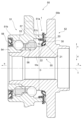
- FIG. 1 is a cross-sectional view of a hub seal 1 according to an embodiment of the present invention, which is manufactured by a method for manufacturing a hub seal according to the present invention, taken along axis x.
- a hub seal manufactured by the hub seal manufacturing method according to the present invention has a side lip, an outer peripheral side member and an inner peripheral side rotatable relative to the outer peripheral side member at least partially surrounded by the outer peripheral side member.
- the hub seal 1 according to the embodiment of the present invention is used in a hub bearing 50 and includes an outer ring 51 as an outer peripheral member capable of relative rotation about an axis and a hub as an inner peripheral member. 52 (see FIG. 3).
- the side in the direction of the arrow a (see FIG. 1) in the direction of the axis x is defined as the outside, and the side in the direction of the arrow b (see FIG. 1) in the direction of the axis x (in the direction of the axis the other side) to the inside.
- the outer side refers to the direction away from the space between the outer ring 51 and the hub 52, which is the space to be sealed, in the direction of the axis x
- the inner side refers to the side to be sealed in the direction of the axis x. It is the side in the direction approaching the space.
- the direction away from the axis x (direction of arrow c in FIG. 1) is defined as the outer peripheral side, and the direction approaching the axis x (direction of FIG. 1) is defined as the inner peripheral side.
- the direction of arrow d) is defined as the inner peripheral side. Note that the axis x is a virtual line.
- the hub seal 1 includes an annular reinforcing ring 10 around the axis x, and an elastic body portion 20 attached to the reinforcing ring 10 and formed of an elastic body annular around the axis x.
- the elastic body portion 20 has a side lip 30 , an intermediate lip 21 and a main lip 22 .
- the side lip 30 extends outward (in the direction of the arrow a) formed to come into contact with the hub 52 from the inside (in the direction of the arrow b) when the hub seal 1, which will be described later, is attached to the hub bearing 50 and is in use. It is a seal lip.
- the intermediate lip 21 is a seal lip that extends outward on the inner peripheral side of the side lip 30 and is formed to come into contact with the hub 52 from the inside when used.
- the main lip 22 is a seal lip formed to come into contact with the hub 52 from the outer peripheral side in use.
- the side lip 30 has a shape that suppresses torque turbulence of the hub 52 and deterioration of the sealing performance of the side lip 30. reaction force F) divided by the diameter of the hub 52 (hub diameter D) (lip reaction force F/hub diameter D), value (lip surface roughness R).
- the hub seal 1 will be specifically described below.
- the reinforcing ring 10 is, for example, as shown in FIG. 1, an annular metal member having an axis x as a central axis or a substantially central axis, and is press-fitted into a through hole of an outer ring 51 of a hub bearing 50 to be described later.
- the hub seal 1 is fixed to the outer ring 51 by pressing the reinforcing ring 10 into the outer ring 51 .
- the reinforcing ring 10 includes a cylindrical fitting portion 11, a position adjusting portion 12 that bends inward from an inner end of the fitting portion 11 and extends outward, and a fitting portion. It has an annular or substantially annular flange portion 13 extending from the outer end portion of the portion 11 to the outer peripheral side.
- the fitting portion 11 is, for example, a cylindrical or substantially cylindrical portion having the axis x as a central axis or substantially a central axis. It is formed to be press-fitted into the outer opening 51a and fitted to its inner peripheral surface.
- the position adjusting portion 12 is shaped such that the side lip 30 , the intermediate lip 21 and the main lip 22 are arranged at desired positions on the hub seal 1 .
- the position adjusting portion 12 has a return portion 12a, a connection flange portion 12b, a return portion 12c, and a lip flange portion 12d.
- the return portion 12a is, for example, a portion having a substantially conical tubular or substantially cylindrical portion that bends from the inner end of the fitting portion 11 and returns to the outside.
- the connection flange portion 12b is, for example, an annular or substantially annular portion extending from the outer end of the return portion 12a to the inner peripheral side.
- the return portion 12c is, for example, a conical tubular or substantially conical tubular portion that obliquely extends from the inner peripheral end of the connection flange portion 12b toward the inside and the inner peripheral side.
- the lip flange portion 12d is, for example, an annular or substantially annular portion extending from the inner peripheral end of the return portion 12c to the inner peripheral side.
- the flange portion 13 is, for example, as shown in FIG.
- the reinforcing ring 10 is formed as an integral member by pressing or forging a metal plate. and are integrally continuous.
- metal materials for the reinforcing ring 10 include stainless steel and SPCC (cold rolled steel).
- the elastic body part 20 is attached to the reinforcing ring 10 as described above, and is formed integrally with the reinforcing ring 10 so as to cover the reinforcing ring 10 from the outside, as shown in FIG. 1, for example.
- the elastic body portion 20 has a base portion 23, for example.
- the base portion 23 is a portion that supports the side lip 30 , the intermediate lip 21 and the main lip 22 , and the side lip 30 , the intermediate lip 21 and the main lip 22 each extend from the base portion 23 .
- the intermediate lip 21 and the main lip 22 for example, extend from the inner peripheral end of the base body 23 , and the side lip 30 extends radially from the intermediate lip 21 on the outer peripheral side of the intermediate lip 21 , for example.
- the base portion 23 spreads over the outer surface of the reinforcing ring 10 across, for example, the flange portion 13 , the fitting portion 11 and the position adjusting portion 12 of the reinforcing ring 10 .
- FIG. 2 is a partially enlarged cross-sectional view showing the vicinity of the side lip 30, intermediate lip 21, and main lip 22 of the hub seal 1 in an enlarged manner.
- the side lip 30 annularly extends outward from the base portion 23 with the axis x as a central axis or approximately the central axis. is formed to contact the hub 52 with a predetermined interference.
- the side lip 30 has, for example, a conical tubular shape or a substantially conical tubular shape that expands in diameter toward the outside in the direction of the axis x.
- the intermediate lip 21 extends outward from the base portion 23 in an annular shape with the axis x as a central axis or approximately the central axis. is formed to contact the hub 52 with a predetermined interference.
- the intermediate lip 21 has, for example, a conical tubular shape or a substantially conical tubular shape that expands in diameter toward the outside in the direction of the axis x.
- the intermediate lip 21 may extend outward in parallel with the side lip 30 and, as shown in FIGS. Also, the opposite may be true.
- the main lip 22 annularly extends from the base portion 23 toward the inner side and the inner peripheral side with the axis x as the central axis or approximately the central axis.
- the main lip 22 is formed so that the tip portion of the seal surface 22a comes into contact with the hub 52 from the outer peripheral side with a predetermined interference when the hub seal 1, which will be described later, is used.
- the seal surface 31 of the side lip 30, the seal surface 21a of the intermediate lip 21, and the seal surface 22a of the main lip 22 are each coated with grease (not shown) as a lubricant.
- the sealing surface 31 of the side lip 30, the sealing surface 21a of the intermediate lip 21, and the sealing surface 22a of the main lip 22 are surfaces facing the inner peripheral sides of the side lip 30, the intermediate lip 21, and the main lip 22, respectively. be.
- the interference of the seal lip is the length by which the seal lip in a free state, which is not deformed by an external force, protrudes from the contact surface with which the seal lip contacts during use.
- the interference of the side lip 30 is the portion of the seal surface 31 that protrudes from the surface of the hub 52 (the inner peripheral surface 55d of the wheel mounting flange 55b), which is the contact surface indicated by the virtual line V in FIG. It is the length in the direction of the axis x.
- the interference of the intermediate lip 21 is the length of the portion of the seal surface 21a projecting from the contact surface of the hub 52 (the transition portion 55c of the wheel mounting flange 55b) indicated by the phantom line V in the direction of the axis x.
- the interference of the main lip 22 is the radial length of the portion of the seal surface 22a that protrudes from the contact surface of the hub 52 (the outer peripheral surface 55e of the shaft portion 55a) indicated by the phantom line V.
- an outer peripheral ring projection 24 is formed on the elastic body portion 20, as shown in FIG. 1, for example.
- the outer ring projection 24 is an annular projection that protrudes outward from the side lip 30 and protrudes outwardly around the axis x. It is formed to form an annular gap therebetween.
- the outer ring projection 24 protrudes outward from, for example, an end portion on the outer peripheral side of the base portion 23 and extends in a conical or substantially conical cylindrical shape with the axis x as a central axis or approximately central axis.
- the elastic body portion 20 has, for example, as shown in FIG.
- the dam portion 25 is formed to protrude outward from the outer end face of the outer ring 51 when the hub seal 1 is attached to the outer ring 51 .
- the dam portion 25 is formed so as to cover the outer peripheral end portion of the flange portion 13 of the reinforcing ring 10 .
- the elastic body portion 20 has a gasket portion 26 that at least partially covers the inner surface of the flange portion 13 of the reinforcing ring 10, as shown in FIG. 1, for example.
- the gasket portion 26 extends annularly around the axis x and continues to the end of the weir portion 25 on the inner peripheral side.
- the elastic body portion 20 is integrally attached to the reinforcing ring 10, and the side lip 30, the intermediate lip 21, the main lip 22, the base portion 23, the outer peripheral ring projection 24, the weir portion 25, and the gasket portion 26 described above are , are each portion of the elastic body portion 20 integrally formed from the same material, and are integrally continuous.
- Examples of the elastic body of the elastic body portion 20 include various rubber materials.
- Various rubber materials are, for example, synthetic rubbers such as nitrile rubber (NBR), hydrogenated nitrile rubber (H-NBR), acrylic rubber (ACM), and fluorine rubber (FKM).
- the shape of the reinforcing ring 10 is not limited to the shape described above, and may be other shapes.
- the reinforcing ring 10 may, for example, be in the form of a known hub seal reinforcing ring having a side lip, a middle lip and a main lip.
- the reinforcing ring 10 does not have to have the flange portion 13 .
- the shape of the elastic body portion 20 is not limited to the shape described above, and may be another shape.
- the elastomeric portion 20 may, for example, be in the form of the elastomeric portion of a known hub seal having a side lip, an intermediate lip and a main lip.
- the elastic body portion 20 may not have the outer peripheral ring projection 24 .
- the elastic body portion 20 may not have the weir portion 25 .
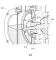
- FIG. 3 is a cross-sectional view of the hub bearing 50 taken along the axis x (hereinafter also simply referred to as "cross section") to show how the hub seal 1 attached to the hub bearing 50 is used
- FIG. 4 is a partially enlarged cross-sectional view of the vicinity of the hub seal 1 in FIG. 3; FIG.
- the axis x of the hub seal 1 coincides or substantially coincides with the axis of the hub bearing 50 .
- the hub bearing 50 is a conventionally known hub bearing, is provided in a vehicle such as an automobile, and rotatably supports a wheel in an axle or suspension system. Specifically, as shown in FIG.
- the hub bearing 50 includes an annular outer ring 51 having an axis x as a member on the outer peripheral side as a central axis or a substantially central axis, and an outer ring 51 which is rotatable relative to the outer ring 51.
- a hub 52 as an inner peripheral member having an axis x partially surrounded by 51 as a central axis or approximately a central axis, and a plurality of bearing balls 53 disposed between the outer ring 51 and the hub 52. ing.
- the hub bearing 50 attached to a vehicle or the like is in use, the outer ring 51 is fixed and the hub 52 is rotatable relative to the outer ring 51 .
- the hub 52 has an inner ring 54 and a hub ring 55.
- the hub ring 55 includes a cylindrical or substantially cylindrical shaft portion 55a extending along the axis x and a wheel mounting flange 55b. have.
- the wheel mounting flange 55b is a portion extending in a disc shape from one outer end of the shaft portion 55a toward the outer circumference, and is a portion to which wheels (not shown) are mounted with a plurality of hub bolts.
- the shaft portion 55a and the wheel mounting flange 55b are smoothly connected on the inner peripheral side, and the transition portion 55c, which is the portion where the shaft portion 55a and the wheel mounting flange 55b are connected on the inner peripheral side, extends along the axis x. It has an arcuate or arcuate smooth curved profile in cross section.
- the inner ring 54 is fitted to the inner end of the shaft portion 55a of the hub wheel 55 to hold the bearing balls 53 in the space between the outer ring 51 and the inner ring 54. As shown in FIG. A retainer 56 retains the bearing balls 53 in the space between the outer ring 51 and the hub 52 .
- the outer ring 51 has a through hole 57 extending in the direction of the axis x.
- a shaft portion 55 a of a hub wheel 55 of the hub 52 is inserted into the through hole 57 .
- An annular space extending along the axis x is formed therebetween. In this space, the bearing balls 53 are accommodated and held by the retainer 56 as described above, and a lubricant is applied or injected.
- the outer opening 51a of the outer ring 51 forms an opening in which the space between the shaft portion 55a and the through hole 57 is open to the outside.
- Another sealing device 58 is attached to the inner opening 51b of the outer ring 51 which forms an opening which is open on the inside.
- the space between the shaft portion 55a and the inner ring 54 and the through hole 57 is sealed by the hub seal 1 and the sealing device 58 to prevent the internal lubricant from leaking to the outside. It is designed to prevent foreign matter such as rain water, muddy water, and dust from entering the interior.
- the sealing device 58 is a conventionally known sealing device, and detailed description thereof will be omitted. As the sealing device 58, the hub seal 1 can also be applied.
- the configuration of the hub bearing to which the hub seal 1 is applied is not limited to the configuration of the hub bearing 50 described above.
- the hub seal 1 is attached to the outer opening 51a of the outer ring 51.
- the hub seal 1 is fixed to the outer ring 51 by press-fitting the fitting portion 11 of the reinforcing ring 10 into the outer opening 51 a of the outer ring 51 .
- the outer peripheral surface 11a of the fitting portion 11 of the reinforcing ring 10 is in contact with the inner peripheral surface 51c of the outer opening 51a of the outer ring 51, so that the reinforcing ring 10 and the outer ring 51 are sealed.
- the flange portion 13 of the reinforcing ring 10 is positioned so that the gasket portion 26 of the elastic body portion 20, which spreads inward, forms an annular surface facing the outside of the outer opening portion 51a. is attached to the outer ring 51 so as to press against the outer end surface 51d forming the .
- the gasket portion 26 is compressed between the outer end face 51d and the flange portion 13, and the sealing performance between the outer ring 51 and the hub seal 1 is improved.
- the outer peripheral ring projection 24 and the weir portion 25 of the elastic body portion 20 also serve to prevent foreign matter from entering.
- the tip of the sealing surface 31 of the side lip 30 contacts the surface of the hub wheel 55, for example, the inner surface of the wheel mounting flange 55b ( A hub wheel 55 is slidably in contact with the inner surface 55d). Further, the tip portion of the intermediate lip 21 is in contact with the surface of the hub wheel 55, for example, the transition portion 55c, in a portion (contact width) corresponding to the above-mentioned predetermined interference so that the hub wheel 55 can slide. Further, the tip portion of the main lip 22 is attached to the surface of the hub wheel 55, for example, the outer peripheral surface 55e, which is the outer peripheral surface of the shaft portion 55a, at the portion (contact width) corresponding to the above-described predetermined interference. are in slidable contact. The side lip 30 and the intermediate lip 21 prevent foreign matter from entering the through hole 57 , and the main lip 22 prevents lubricant from flowing out of the through hole 57 .
- the seal surface 31 of the side lip 30, the seal surface 21a of the intermediate lip 21, and the seal surface 22a of the main lip 22 are each coated with grease. Therefore, in use, as shown in FIG. 4, grease G is interposed between the contact surfaces of the side lip 30 and the inner surface 55d of the wheel mounting flange 55b. Similarly, the grease G intervenes between the contact surfaces of the intermediate lip 21 and the transition portion 55c of the wheel mounting flange 55b, and the contact surfaces of the main lip 22 and the outer peripheral surface 55e of the shaft portion 55a. Grease G is interposed between .
- the inner surface 55d of the wheel mounting flange 55b of the hub wheel 55 with which the side lip 30 contacts may have a work mark formed during the manufacturing of the hub bearing 50.
- this processing pattern forms a groove having a certain directionality, and depending on the degree of surface roughness of this processing pattern, a pump action is generated based on this processing pattern when the hub 52 rotates. I have something to do. Due to this pumping action, the air, grease G, etc. in the space S surrounded by the side lip 30, the wheel mounting flange 55b of the hub wheel 55, the intermediate lip 21, and the base portion 23 are discharged from the space S to the outside. , the pressure in the space S may become lower than the pressure of the outside atmosphere, and the pressure in the space S may become negative.
- the inventors of the present invention have investigated the occurrence of the rotational torque disturbance of the hub 52 (hereinafter also referred to as "torque disturbance"), the lip reaction force F of the side lip 30, and the lip surface roughness of the sealing surface 31 of the side lip 30.
- the hub diameter D of the hub 52 is the diameter of the portion of the hub wheel 55 to which the radial dimension of the hub seal 1 relates.
- the hub diameter D of the hub 52 is, for example, the diameter of the portion of the hub wheel 55 associated with setting the diameter dimension of the side lip 30 .
- the hub diameter D is the diameter of the outer peripheral surface 55e of the shaft portion 55a of the hub wheel 55 or the diameter of the transition portion 55c of the wheel mounting flange 55b of the hub wheel 55 at any position.
- the inventors of the present invention have found that when the hub seal is in use and negative pressure is generated in the space formed by the side lip (see space S), the hub rotation torque disturbance and abnormal noise are caused by the contact of the side lip sealing surface. It was presumed that the stick-slip occurred because the oil film of grease was no longer formed on the surface (sliding surface), and the contact surface of the side lip was intermittently caught on the sliding hub. The reason why the oil film of grease is not formed on the contact surface (sliding surface) of the side lip seal surface is related to the magnitude of the reaction force of the side lip and the degree of surface roughness of the side lip seal surface. I assumed.
- the present inventors prepared a plurality of hub seals 1 having different values of lip reaction force F of the side lip 30 and different values of lip surface roughness R of the seal surface 31 of the side lip 30, and prepared a plurality of hub seals. 1, an evaluation test was conducted to confirm the occurrence of hub torque disturbance and deterioration of sealing performance.
- the lip reaction force F of the side lip 30 is applied to the inner surface 55d of the wheel mounting flange 55b of the hub wheel 55 by the side lip 30 in the direction of the axis x when the hub seal 1 is in use.
- Elements of the side lip 30 that determine the lip reaction force F of the side lip 30 include, for example, the angle of the extending direction e of the side lip 30 with respect to the radial direction (lip angle A), the extending direction of the side lip 30, and (lip length L), the thickness of the side lip 30 in the direction orthogonal to the extending direction (lip thickness DL), and the shape of the root of the side lip 30 .
- these elements of the side lip 30 are values in a cross section along the axis x of the side lip 30.
- the extending direction e of the side lip 30 is the direction in which the contour line of the sealing surface 31 in the cross section of the side lip 30 extends.
- the contour line of the sealing surface 31 in the cross section of the side lip 30 is straight or substantially straight.
- the lip length L is the length of the contour line of the sealing surface 31 in the cross section of the side lip 30, as shown in FIG. It is the length between the lip 30 and the root end of the seal surface 31 (seal surface root end 33).
- the lip thickness DL of the side lip 30 is constant over the extending direction of the side lip 30, and is the thickness between the outer peripheral surface 34, which is the surface facing the outer peripheral side of the side lip 30, and the seal surface 31. interval.
- the contour line of the outer peripheral surface 34 in the cross section of the side lip 30 is a straight line or a substantially straight line.
- the lip thickness DL of the side lip 30 may not be constant in the extending direction of the side lip 30, and may be substantially constant in the extending direction of the side lip 30. It may be.
- the side lip 30 has a lip tip portion 35 and a lip root portion 36.
- the shape of the root of the side lip 30, which is a factor that determines the lip reaction force F of the side lip 30, is shown in FIG. is the shape and size of a particular portion of the lip base portion 36.
- the outer peripheral surface 36a of the lip root portion 36 is, for example, a curved surface that smoothly connects to the base portion 23. As shown in FIG. Draw a convex curve on the side.
- the inner peripheral surface 36b of the lip base portion 36 is a cylindrical surface or a substantially cylindrical surface that extends mainly along the axis x. It is smoothly connected to the base portion 23 and curved.
- the shape of the root of the side lip 30, which is a factor that determines the lip reaction force F of the side lip 30, is, for example, the radial thickness of the lip root portion 36, the lip thickness DLb, the curvature of the outer peripheral surface 36a, and the inner diameter.
- the curvature of the inner peripheral surface 36b also becomes the shape of the root of the side lip 30, which is a factor that determines the lip reaction force F of the side lip 30.
- the lip tip portion 35 is a portion surrounded by the seal surface 31, the outer peripheral surface 34, and the seal tip edge 37.
- the lip base portion 36 is a portion connected to the base portion 23, and the lip tip portion 35 and the base portion 23 are connected. is the part between Further, the radial thickness DLb of the lip root portion 36 is the radial thickness at the innermost position of the outer peripheral surface 36a of the lip root portion 36, as shown in FIG. 5, for example. 5 is a virtual boundary line between the lip tip portion 35 and the lip root portion 36, and a virtual line B2 in FIG. 5 is a virtual boundary line between the lip root portion 36 and the base portion 23. is.
- the lip reaction force F in Test Examples 1 to 25 was measured using the reaction force measuring device E1 shown in FIG. Specifically, the hub seal 1 (test examples 1 to 25) is fixed to the lower arm E3, the load cell E5 with the disc E4 attached is attached to the upper arm E2, the upper arm E2 is moved toward the lower arm E3, and the hub seal 1 is The disk E4 was brought into contact with the side lip 30 of the side lip 30, and the force that the disk E4 receives from the side lip 30 at this time was measured by the load cell E5 to measure the lip reaction force F.
- the hub seal 1 is fixed to the lower arm E3 in such a posture that the side lip 30 faces the upper arm E2.
- the lip reaction force F to be measured is the lip reaction force F when the contact width of the side lip 30 with respect to the disk E4 becomes the width corresponding to the interference of the side lip 30 in the usage state of the hub seal 1.
- the test apparatus E10 has a rotating shaft E11 rotatable around its axis, and a hub dummy E12 is attached to the tip of the rotating shaft E11.
- the hub dummy body E12 includes the inner surface 55d of the wheel mounting flange 55b of the hub wheel 55 and the transition portion 55c with which the side lip 30, the intermediate lip 21, and the main lip 22 are in contact when the hub seal 1 is used as shown in FIG. It also has a surface E13 having the same shape as the outer peripheral surface 55e of the shaft portion 55a of the hub wheel 55. As shown in FIG.
- the test apparatus E10 has an outer ring dummy body E14, which is the same as the outer opening 51a of the outer ring 51 into which the reinforcing ring 10 is press-fitted when the hub seal 1 shown in FIG. 4 is used. It has a fixed part E15 which is a shaped part. In other words, the fixing portion 15 has surfaces having the same shape as the inner peripheral surface 51c and the outer end surface 51d of the outer opening 51a of the outer ring 51 .
- a hub seal 1 is attached between the outer ring dummy body E14 and the hub dummy body E12.
- the reinforcing ring 10 is press-fitted into the fixing portion E15 of the outer ring pseudo body E14, and the side lip 30, the intermediate lip 21, and the main lip 22 contact the surface E13 of the hub pseudo body E12.
- the contact width of the side lip 30 with respect to the surface E13 corresponds to the interference of the side lip 30 when the hub seal 1 is in use.
- the contact width of the main lip 22 with respect to the surface E13 corresponds to the interference of the main lip 22 when the hub seal 1 is used.
- a closed head E16 forming a closed space for storing muddy water is formed outside the outer ring pseudo body E14 and the hub pseudo body E12, and muddy water is enclosed in the closed head E16.
- a water leakage sensor E17 is attached to a position near the hub seal 1 on the inner peripheral surface of the outer ring pseudo body E14. The water leakage sensor E17 detects the leaked muddy water when the muddy water leaks over the hub seal 1 to the inside.
- the muddy water that has leaked over the hub seal 1 accumulates in the vicinity of the hub seal 1 on the lower portion of the inner peripheral surface of the outer ring pseudo-body E14.
- the torque of the rotating shaft E11 is detected using a torque measuring device E18.
- the torque measuring device E18 detects the torque of the rotating shaft E11 at predetermined intervals.
- the detection result of the water leak sensor E17 was checked, and it was confirmed whether the water leak sensor E17 was activated during the test.
- the water leakage sensor E17 was activated during the test, it was determined that muddy water had leaked, and the sealing performance was evaluated as degraded.
- the detected value of the torque measuring device E18 or the calculated value based on this detected value is larger than a predetermined threshold value, it is determined that there is torque disturbance.
- the presence or absence of torque turbulence is determined, for example, by storing the detected values of the torque measuring device E18 detected during a predetermined test time, and the detected values detected during the stored predetermined test time, or these detected values.
- a torque detection value smaller than a predetermined threshold or A ratio (torque stability) of the calculated value is calculated, and if this ratio (torque stability) is equal to or less than another predetermined threshold value, it is determined that there is torque disturbance.
- the average value of the torque detection values detected by the torque measuring device E18 or the calculated values based on these torque detection values is obtained at a predetermined sampling period, and this average value is further compared with another predetermined threshold value, The presence or absence of torque disturbance may be determined.
- the calculated value based on the torque detection value is, for example, the standard deviation of the torque detection values detected by the torque measuring device E18 at a predetermined sampling period.
- the above-described method for determining the presence or absence of torque disturbance is an example, and other methods may be used to determine the presence or absence of torque disturbance.
- the graph in FIG. 8 shows the evaluation test results of Test Examples 1 to 25.
- the graph of FIG. 8 shows the values of the lip reaction force F per unit length of the side lip 30 and the lip surface roughness R of the side lip 30 in each of Test Examples 1-25.
- the graph of FIG. 8 shows the relationship between the lip reaction force F per unit length of the side lip 30 and the lip surface roughness R of the side lip 30 in Test Examples 1-25.
- the value of the lip reaction force F per unit length of the side lip 30 means that the lip reaction force F of the side lip 30 is applied to the outer peripheral surface 55e of the shaft portion 55a of the hub wheel 55 on the surface E13 of the hub pseudo body E12.
- the hub pseudo body diameter DE is a value corresponding to the hub diameter D.
- the values of lip reaction force F/pseudo-hub body diameter DE of each of Test Examples 1 to 25 are shown on the horizontal axis, and the values of lip surface roughness R of each of Test Examples 1 to 25 are shown on the vertical axis. It is In FIG. 8, white circles are plots corresponding to test examples in which torque disturbance did not occur, and black circles are plots corresponding to test examples in which torque disturbance occurred.
- the torque disturbance region is a region in which torque disturbance is assumed to occur, and the side lip 30 having a value within the torque disturbance region can be determined to be the side lip 30 in which torque disturbance occurs.
- the sealing performance deterioration region is a region in which the sealing performance deteriorates, and the side lip 30 having a value within the sealing performance deterioration region can be determined to be the side lip 30 in which muddy water leaks and the sealing performance deteriorates. . If the value of the lip reaction force F is small, the sealing performance will deteriorate, and if the value of the lip surface roughness R is large, the sealing performance will deteriorate.
- the value of the lip reaction force F of the side lip 30 per unit length (lip reaction force F/hub pseudo body diameter DE), the lip surface roughness R of the side lip 30,
- the occurrence of torque disturbance and between the value per unit length of the lip reaction force F of the side lip 30 and the lip surface roughness R of the side lip 30 and the deterioration of the sealing performance. are found to be related.
- a region in which torque disturbance occurs can be set with respect to the value of the lip reaction force F of the side lip 30 per unit length and the value of the lip surface roughness R of the side lip 30. It can be seen that the region in which the sealing performance is lowered can be set for the value of the lip reaction force F per unit length of 30 and the lip surface roughness R of the side lip 30 .
- the setting of the torque disturbance region and the seal performance deterioration region is based on the value of the lip reaction force F per unit length of the side lip 30 (lip reaction force F/hub pseudo body diameter DE) obtained by the evaluation test described above, It can be set based on the value of the lip surface roughness R of the side lip 30 .
- the torque disturbance region is set by plotting the evaluation test results on a graph such as that shown in FIG. 8 and setting a region that includes all of the plots indicating the presence of torque disturbance.
- the boundary line of the torque disturbance region can be set by connecting the plots with torque disturbance with a smooth line.
- the boundary line of the torque turbulence region is such that the value of the lip surface roughness R of the side lip 30 increases as the lip reaction force F of the side lip 30 per unit length, which includes the plot with torque turbulence, increases. It can be set by drawing a line that grows larger. This is because stick-slip is more likely to occur as the lip reaction force F increases. It is thought that the line is such that the value of the lip surface roughness R of No. 30 increases.
- the boundary line of the torque disturbance region is, for example, an inclined straight line, and for example, a quadratic function in which the slope of the tangent line decreases as the value per unit length of the lip reaction force F increases. curve.
- the boundary line of the torque disturbance region is not limited to the slanted straight line or the quadratic function curve described above, but may be various lines based on the plot with torque disturbance.
- the seal performance degradation region is set by plotting the evaluation test results on a graph such as that shown in Fig. 8 and setting a region that includes all plots with seal performance degradation.
- the boundary line of the sealing performance degradation region can be set by connecting the plots with the sealing performance degradation with a smooth line.
- the boundary line of the sealing performance degradation region is such that the lip surface roughness R of the side lip 30, which includes plots indicating that the sealing performance is degraded, increases, and the lip reaction force F per unit length of the side lip 30 increases. It can be set by drawing a line that increases the value. It is considered that the more the lip reaction force F increases, the more difficult it is for muddy water to enter, and the greater the lip surface roughness R, the easier it is for muddy water to enter.
- the boundary line of the degraded sealing performance area is, for example, an inclined straight line, and is a quadratic curve in which the slope of the tangential line decreases as the value of the lip surface roughness R of the side lip 30 increases.
- the boundary line of the sealing performance deterioration region is not limited to the slanted straight line or the above-mentioned quadratic function curve, but various lines based on the plot of the presence of sealing performance deterioration.
- a plot that is assumed to be closest to the seal performance deterioration region from the evaluation test results is selected for each lip surface roughness R or for each predetermined range of lip surface roughness R, and this selection Based on the obtained plot, the seal performance degradation region can be set.
- plots selected as described above can be connected by a smooth line to set the region of degraded sealing performance.
- each of the plots selected as described above can be moved by a predetermined width in a direction approaching the sealing performance degradation region, and these plots can be connected by a smooth line to set the sealing performance degradation region.
- the unit length of the lip reaction force F in each group of plots in which the lip surface roughness R is close to each other such as the boundary line of the seal performance deterioration region shown in FIG.
- the plot with the smallest value per unit length is selected, and the line passing through the side where the value per unit length of the lip reaction force F is smaller than the selected plot by a predetermined width is taken as the boundary line of the region of decreased sealing performance. can do.
- the unit length of the lip reaction force F of the side lip 30 is considered to prevent torque turbulence and seal performance deterioration.
- a design area which is the range of the hit value and the lip surface roughness R of the side lip 30, can be set.
- the design region is a region in which the value per unit length of the lip reaction force F of the side lip 30 and the lip surface roughness R of the side lip 30 are not included in the torque disturbance region and the sealing property deterioration region.
- a specific area (target area) within the design area may be set as the value per unit length of the lip reaction force F of the side lip 30 and the range of the lip surface roughness R of the side lip 30 .
- the specific target area is, for example, an area within the design area that is separated by a predetermined width from each of the boundary of the torque disturbance area and the boundary of the degraded sealing performance area. Further, the specific target area is, for example, a range of values per unit length of a specific lip reaction force F within the design area and a range of specific lip surface roughness R within the design area.
- the side lip 30 entering the area (target area I) indicated by the broken line frame in FIG. It is possible to set the area of the side lip 30 in which the sealing performance is not deteriorated.
- the value of “lip reaction force F/hub pseudo body diameter DE” is 0.05 N/mm or more and 0.09 N/mm or less
- the value of lip surface roughness R is RzJIS10 ⁇ m ⁇ or more and RzJIS10 ⁇ m+ ⁇ or less is defined as the target area.
- ⁇ is, for example, a tolerance during molding of the side lip 30, and is a value that takes into consideration variations in the lip surface roughness R that may occur during manufacture of the side lip 30.
- the value of the lip reaction force F of the side lip 30 per unit length ie, the value of the lip reaction force F of the side lip 30/hub
- the value of the diameter D" and the lip surface roughness R result in the side lip 30 falling within the design range.
- the value of the lip reaction force F/hub diameter D of the side lip 30 and the lip surface roughness R are within the target region I shown in FIG. It becomes the side lip 30 which enters.
- the value of "lip reaction force F/hub diameter D" of the side lip 30 of the hub seal 1 is 0.05 N/mm or more and 0.09 N/mm or less.
- the lip reaction force F is adjusted based on at least one of the lip angle A, lip thickness DL, lip length L, and shape of the lip base portion 36 of the side lip 30, and the shape of the side lip 30 of the hub seal 1 is:
- the shape is such that the value of "lip reaction force F/hub diameter D" is 0.05 N/mm or more and 0.09 N/mm or less.
- the shape of the side lip 30 of the hub seal 1 can be changed to a "lip
- the shape is such that the value of "reaction force F/hub diameter D" is 0.05 N/mm or more and 0.09 N/mm or less.
- the value of the lip surface roughness R of the side lip 30 of the hub seal 1 is RzJIS 10 ⁇ m ⁇ or more and RzJIS 10 ⁇ m+ ⁇ or less.
- the boundary of the torque disturbance region and the boundary of the seal performance degradation region are determined based on the results of the evaluation test, the design concept of the safety factor, etc., and other factors such as the shape of the hub seal 1. Based on this, various boundaries can be used, and the design area can also be various areas accordingly. Similarly, the target area can also be set to various areas. For example, there may be a torque disturbance region, a seal performance deterioration region, a design region, and a target region as shown in FIG.
- the above-described evaluation test is performed to set the design area in advance, and in the elastic body portion forming step of forming the elastic body portion 20 of the hub seal 1 from an elastic material, select the value of "lip reaction force F/hub diameter D" and lip surface roughness R that fall within this preset design range, and select the value of "lip reaction force F/hub diameter D” and the lip surface roughness R
- a side lip 30 having a surface roughness R is designed, and the designed side lip 30 is manufactured.
- the side lip 30 has a shape that suppresses torque disturbance and deterioration of sealing performance.
- the side lip 30 can easily design the hub seal 1 in a short period of time so as to suppress torque disturbance and deterioration of sealing performance.
- the side lip 30 having the selected value of "lip reaction force F/hub diameter D" and the lip surface roughness R, the lip reaction force F of the side lip 30 is At least one of the lip angle A, lip length L, lip thickness DL, lip surface roughness R, and shape of the lip root portion 36 of the lip 30 is adjusted and designed.
- the shape of the side lip 30 is set so that the value of "lip reaction force F/hub diameter D" of the side lip 30 and the lip surface roughness R are in the target region shown in FIG. It is designed in a shape that fits inside I. More specifically, for example, in the method of manufacturing the hub seal, the value of "lip reaction force F/hub diameter D" of the side lip 30 is 0.05 N/mm or more and 0.09 N/mm or less.
- the side lip 30 is designed so that the lip surface roughness R is RzJIS 10 ⁇ m ⁇ or more and RzJIS 10 ⁇ m+ ⁇ or less.
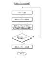
- FIG. 10 shows a flowchart of hub seal manufacturing processing for manufacturing the hub seal 1 .
- a design region, a torque disturbance region, and a seal performance deterioration region are preset based on the lip reaction force F/hub diameter D and the lip surface roughness R. is referenced (step S1).
- the side lip design standard data is a combination of "lip reaction force F/hub diameter D” and lip surface roughness R belonging to the design area, and “lip reaction force F/hub diameter D” and lip surface roughness belonging to the torque disturbance area. 8 and 9, and the combination of "lip reaction force F/hub diameter D” and lip surface roughness R belonging to the sealing performance deterioration region. is.
- step S2 a combination of "lip reaction force F/hub diameter D" and lip surface roughness R belonging to the design area is selected from side lip design standard data.
- step S3 the hub seal 1 having the side lip 30 having the "lip reaction force F/hub diameter D" selected in step 2 and the lip surface roughness R is designed (step S3).
- step S4 the hub seal 1 designed in step 3 is manufactured (step S4).
- FIG. 11 shows a flow chart showing a process for creating standard side lip design data referred to in step 1 of the hub seal manufacturing process shown in FIG.
- step S11 a plurality of hub seals 1 (sample hub seals) having side lips 30 with different combinations of "lip reaction force F/hub diameter D" and lip surface roughness R are prepared.
- step S11 each sample hub seal prepared in step S11 is subjected to an evaluation test for confirming occurrence of torque disturbance of the hub and deterioration of sealing performance.
- step S13 the combination of "lip reaction force F/hub diameter D" and lip surface roughness R of each sample hub seal is classified into the design area, torque disturbance area, or seal performance deterioration area. and store (step S13). This creates side lip design standard data.
- the classification in step S13 is performed by plotting the "lip reaction force F/hub diameter D" of each sample hub seal on the graph of "lip reaction force F/hub diameter D" and lip surface roughness R as shown in FIGS. and lip surface roughness R, and also link the evaluation results of each sample hub seal in step S12 to the corresponding plots to set the boundaries of the torque disturbance region and the seal performance degradation region, respectively, as described above.
- the combination of "lip reaction force F/hub diameter D" and lip surface roughness R of each sample hub seal is classified into the design area, torque disturbance area, or seal performance deterioration area.
- the method of classifying the combination of "lip reaction force F/hub diameter D" and lip surface roughness R of the sample hub seal into the design area, torque disturbance area, or seal performance deterioration area is the visual method described above. is not limited to For example, the method of classifying the combination of "lip reaction force F/hub diameter D" and lip surface roughness R of the sample hub seal into the design area, torque disturbance area, or seal performance deterioration area is a method based on calculation. may
- FIG. 12 shows a flowchart showing side lip element selection processing for selecting a combination of "lip reaction force F/hub diameter D" and lip surface roughness R in step S2 of the hub seal manufacturing method shown in FIG. It is
- the hub diameter D is set based on the specifications of the hub bearing to which the hub seal 1 is applied (step S21).
- a combination of "lip reaction force F/hub diameter D” and lip surface roughness R belonging to the design area is selected from the side lip design standard data referred to in step S1 of the hub seal manufacturing method shown in FIG. S22).
- the side lip 30 having the "lip reaction force F/hub diameter D" selected in step S22 and the lip surface roughness R is designed (step S23).
- step S24 it is determined whether the side lip 30 designed in step S23 is structurally valid for the hub bearing to which the hub seal 1 is applied.
- step S24 if it is determined to be true (Yes in step S24), in step S25, the combination of "lip reaction force F/hub diameter D" and lip surface roughness R selected in step S22 is selected. It is determined as a combination of "lip reaction force F/hub diameter D” and lip surface roughness R. On the other hand, if it is determined in step S24 that this does not hold (No in step S24), the process returns to step S22 to select a different combination of "lip reaction force F/hub diameter D" and lip surface roughness R belonging to the design area. do.
- FIG. 13 is a diagram showing a flow chart of a conventional hub seal manufacturing method.
- the hub seal is designed based on the specifications of the hub bearing to which the hub seal is to be applied, the designed hub seal is manufactured as a trial, and the torque disturbance of the hub occurs in the prototype hub seal. Perform evaluation tests to confirm performance degradation. Then, when it is determined from this evaluation test that the designed hub seal does not meet the requirements, a new hub seal is designed, a newly designed hub seal is manufactured, and an evaluation test is performed on it. It takes a long time to design this new hub seal, manufacture it, and perform evaluation tests on this newly manufactured hub seal.
- the hub seal manufacturing method according to the embodiment of the present invention, once the side lip design standard data is created, the side lip 30 can be designed without performing an evaluation test, and the hub seal 1 can be manufactured in a shorter period of time. can.
- machining marks are left on the inner surface 55d of the wheel mounting flange 55b and the transition portion 55c of the hub wheel 55 with which the side lip 30 contacts during use. Even if it is, it is possible to suppress the disturbance of the rotation torque of the hub bearing 50 and the occurrence of abnormal noise while suppressing the deterioration of the sealing performance.
- the present invention is not limited to the method of manufacturing a hub seal according to the above-described embodiments of the present invention. including aspects. Moreover, each configuration may be selectively combined as appropriate so as to achieve at least part of the above-described problems and effects.
- Hub diameter DE ... Hub pseudo body diameter DL, DLb... Lip thickness, e... Extension direction, F... Lip reaction force, G... Grease, I... Target area, L... Lip length, R... Lip surface roughness, S... Space, x... Axis line
Landscapes
- Engineering & Computer Science (AREA)
- General Engineering & Computer Science (AREA)
- Mechanical Engineering (AREA)
- Manufacturing & Machinery (AREA)
- Sealing With Elastic Sealing Lips (AREA)
- Rolling Contact Bearings (AREA)
- Sealing Of Bearings (AREA)
Priority Applications (4)
| Application Number | Priority Date | Filing Date | Title |
|---|---|---|---|
| US18/727,253 US12359726B2 (en) | 2022-01-12 | 2022-12-28 | Method of manufacturing hub seal |
| CN202280087339.2A CN118511010A (zh) | 2022-01-12 | 2022-12-28 | 轮毂密封件的制造方法 |
| EP22920675.0A EP4464909A1 (en) | 2022-01-12 | 2022-12-28 | Method for manufacturing hub seal |
| KR1020247021637A KR20240112920A (ko) | 2022-01-12 | 2022-12-28 | 허브 시일의 제조 방법 |
Applications Claiming Priority (2)
| Application Number | Priority Date | Filing Date | Title |
|---|---|---|---|
| JP2022-003360 | 2022-01-12 | ||
| JP2022003360A JP7135224B1 (ja) | 2022-01-12 | 2022-01-12 | ハブシールの製造方法 |
Publications (1)
| Publication Number | Publication Date |
|---|---|
| WO2023136160A1 true WO2023136160A1 (ja) | 2023-07-20 |
Family
ID=83229709
Family Applications (1)
| Application Number | Title | Priority Date | Filing Date |
|---|---|---|---|
| PCT/JP2022/048497 WO2023136160A1 (ja) | 2022-01-12 | 2022-12-28 | ハブシールの製造方法 |
Country Status (6)
Families Citing this family (1)
| Publication number | Priority date | Publication date | Assignee | Title |
|---|---|---|---|---|
| JP7135224B1 (ja) * | 2022-01-12 | 2022-09-12 | Nok株式会社 | ハブシールの製造方法 |
Citations (3)
| Publication number | Priority date | Publication date | Assignee | Title |
|---|---|---|---|---|
| JP3201207U (ja) | 2015-09-15 | 2015-11-26 | 内山工業株式会社 | 密封構造 |
| JP2018084318A (ja) * | 2016-11-25 | 2018-05-31 | Nok株式会社 | 密封装置および密封構造 |
| JP2019113118A (ja) * | 2017-12-25 | 2019-07-11 | 株式会社ジェイテクト | 車輪用軸受装置 |
Family Cites Families (14)
| Publication number | Priority date | Publication date | Assignee | Title |
|---|---|---|---|---|
| JP2002228010A (ja) * | 2000-10-25 | 2002-08-14 | Teijin Seiki Co Ltd | 真空シール機構および真空シール装置 |
| JP2003074491A (ja) * | 2001-09-04 | 2003-03-12 | Nsk Ltd | ウォータポンプ用シール装置とウォータポンプ用回転支持装置とウォータポンプ |
| JP2006161917A (ja) * | 2004-12-06 | 2006-06-22 | Koyo Sealing Techno Co Ltd | 密封装置 |
| JP2012193847A (ja) * | 2011-03-01 | 2012-10-11 | Minebea Co Ltd | 転がり軸受、スロットルバルブ装置及びabs装置 |
| DE102013218635B4 (de) * | 2013-09-17 | 2015-09-24 | Schaeffler Technologies AG & Co. KG | Dichtungsanordnung für Radlager mit vorgespanntem Schleuderblech |
| WO2018087433A1 (fr) * | 2016-11-10 | 2018-05-17 | Hutchinson | Ensemble de joint d'étanchéité, palier à roulement comprenant un tel ensemble, et procédé pour fabriquer cet ensemble |
| JP6874431B2 (ja) * | 2017-03-10 | 2021-05-19 | 中西金属工業株式会社 | 回転用シール |
| JP6520976B2 (ja) * | 2017-03-22 | 2019-05-29 | 株式会社ジェイテクト | 密封型スラスト軸受 |
| US10458477B2 (en) * | 2017-03-28 | 2019-10-29 | Minebea Mitsumi Inc. | Seal for rolling bearing and rolling bearing |
| JP2020122492A (ja) * | 2019-01-29 | 2020-08-13 | 中西金属工業株式会社 | 回転用シールに用いるスリンガの製造方法、及び回転用シール |
| DE102020209677A1 (de) * | 2020-07-31 | 2022-02-03 | Aktiebolaget Skf | Lageranordnung |
| JP7135224B1 (ja) * | 2022-01-12 | 2022-09-12 | Nok株式会社 | ハブシールの製造方法 |
| US20240068519A1 (en) * | 2022-08-23 | 2024-02-29 | Nok Corporation | Sealing Device for Hub Bearing |
| KR20240061847A (ko) * | 2022-11-01 | 2024-05-08 | 현대자동차주식회사 | 씰링장치 및 이를 포함하는 인휠 모터 |
-
2022
- 2022-01-12 JP JP2022003360A patent/JP7135224B1/ja active Active
- 2022-08-24 JP JP2022133372A patent/JP2023102745A/ja active Pending
- 2022-12-28 KR KR1020247021637A patent/KR20240112920A/ko active Pending
- 2022-12-28 WO PCT/JP2022/048497 patent/WO2023136160A1/ja active IP Right Grant
- 2022-12-28 CN CN202280087339.2A patent/CN118511010A/zh active Pending
- 2022-12-28 US US18/727,253 patent/US12359726B2/en active Active
- 2022-12-28 EP EP22920675.0A patent/EP4464909A1/en active Pending
Patent Citations (3)
| Publication number | Priority date | Publication date | Assignee | Title |
|---|---|---|---|---|
| JP3201207U (ja) | 2015-09-15 | 2015-11-26 | 内山工業株式会社 | 密封構造 |
| JP2018084318A (ja) * | 2016-11-25 | 2018-05-31 | Nok株式会社 | 密封装置および密封構造 |
| JP2019113118A (ja) * | 2017-12-25 | 2019-07-11 | 株式会社ジェイテクト | 車輪用軸受装置 |
Also Published As
| Publication number | Publication date |
|---|---|
| US12359726B2 (en) | 2025-07-15 |
| CN118511010A (zh) | 2024-08-16 |
| JP2023102694A (ja) | 2023-07-25 |
| KR20240112920A (ko) | 2024-07-19 |
| JP7135224B1 (ja) | 2022-09-12 |
| US20250084923A1 (en) | 2025-03-13 |
| JP2023102745A (ja) | 2023-07-25 |
| EP4464909A1 (en) | 2024-11-20 |
Similar Documents
| Publication | Publication Date | Title |
|---|---|---|
| US10479139B2 (en) | Wheel bearing apparatus | |
| EP3336395B1 (en) | Sealing device | |
| CN112901663B (zh) | 密封装置 | |
| US7021830B2 (en) | Seal ring and rolling bearing unit with seal ring | |
| WO2013168703A1 (ja) | 密封構造 | |
| JP2018044611A (ja) | 車輪用軸受装置 | |
| JPWO2017061242A1 (ja) | 密封装置 | |
| JP7135224B1 (ja) | ハブシールの製造方法 | |
| JP6093605B2 (ja) | 密封装置及び密封装置を備えた車輪用転がり軸受装置 | |
| JP2017106514A (ja) | 密封装置 | |
| JP2016080020A (ja) | 密封装置 | |
| JP2004068844A (ja) | シールリング及びシールリング付転がり軸受ユニット | |
| JP5104516B2 (ja) | 軸受用密封装置の取付構造 | |
| CN223019219U (zh) | 轮毂轴承密封件 | |
| JP7223908B1 (ja) | ハブシール | |
| US20250012318A1 (en) | Wheel bearing assemblies and vehicles | |
| JP2017101750A (ja) | 密封装置用補助シール | |
| JP2021173368A (ja) | 転がり軸受装置 | |
| JP2018071738A (ja) | 密封構造 | |
| JP6920083B2 (ja) | 車輪用軸受装置 | |
| WO2024058261A1 (ja) | ハブシールの製造方法 | |
| JP2023103567A (ja) | 密封装置 | |
| WO2025033412A1 (ja) | 密封装置 | |
| KR20250082661A (ko) | 휠 베어링의 씰링 구조 및 이를 포함하는 휠 베어링 조립체 | |
| WO2025033414A1 (ja) | 密封装置 |
Legal Events
| Date | Code | Title | Description |
|---|---|---|---|
| 121 | Ep: the epo has been informed by wipo that ep was designated in this application |
Ref document number: 22920675 Country of ref document: EP Kind code of ref document: A1 |
|
| ENP | Entry into the national phase |
Ref document number: 20247021637 Country of ref document: KR Kind code of ref document: A |
|
| WWE | Wipo information: entry into national phase |
Ref document number: 202280087339.2 Country of ref document: CN |
|
| WWE | Wipo information: entry into national phase |
Ref document number: 18727253 Country of ref document: US |
|
| WWE | Wipo information: entry into national phase |
Ref document number: 2401004574 Country of ref document: TH |
|
| WWE | Wipo information: entry into national phase |
Ref document number: 2022920675 Country of ref document: EP |
|
| NENP | Non-entry into the national phase |
Ref country code: DE |
|
| ENP | Entry into the national phase |
Ref document number: 2022920675 Country of ref document: EP Effective date: 20240812 |
|
| WWP | Wipo information: published in national office |
Ref document number: 18727253 Country of ref document: US |
|
| WWG | Wipo information: grant in national office |
Ref document number: 18727253 Country of ref document: US |