WO2023135806A1 - ステアリング装置 - Google Patents
ステアリング装置 Download PDFInfo
- Publication number
- WO2023135806A1 WO2023135806A1 PCT/JP2022/001394 JP2022001394W WO2023135806A1 WO 2023135806 A1 WO2023135806 A1 WO 2023135806A1 JP 2022001394 W JP2022001394 W JP 2022001394W WO 2023135806 A1 WO2023135806 A1 WO 2023135806A1
- Authority
- WO
- WIPO (PCT)
- Prior art keywords
- driver
- rim
- electrode
- spoke
- viewed
- Prior art date
Links
- 230000002093 peripheral effect Effects 0.000 claims description 47
- 238000010586 diagram Methods 0.000 description 4
- 239000000463 material Substances 0.000 description 4
- 238000001514 detection method Methods 0.000 description 3
- 238000005452 bending Methods 0.000 description 2
- 230000000694 effects Effects 0.000 description 2
- 238000007796 conventional method Methods 0.000 description 1
Images


Classifications
-
- B—PERFORMING OPERATIONS; TRANSPORTING
- B62—LAND VEHICLES FOR TRAVELLING OTHERWISE THAN ON RAILS
- B62D—MOTOR VEHICLES; TRAILERS
- B62D1/00—Steering controls, i.e. means for initiating a change of direction of the vehicle
- B62D1/02—Steering controls, i.e. means for initiating a change of direction of the vehicle vehicle-mounted
- B62D1/04—Hand wheels
Definitions
- the present invention relates to steering devices. More specifically, it relates to a steering device that receives a steering operation by a driver.
- a sensor device such as that disclosed in Patent Document 1 detects whether or not the driver is gripping the steering wheel. In some cases, the driver is urged to grip the steering wheel, or the driving support function being executed is canceled.
- the sensor device disclosed in Patent Document 1 detects the contact or proximity of the driver's hand to the steering wheel based on changes in the capacitance of electrodes provided on the spokes of the steering wheel.
- the plate-like electrode is provided on the spoke portion with the flat surface facing the driver's side. Since the electric lines of force induced around the electrodes pass perpendicularly to the electrodes, in the sensor device disclosed in Patent Document 1, the annular rim portion connected to the radially outer side of the spoke portion is grasped. It may not be possible to accurately detect the presence of the hand that moves. In particular, the detection accuracy of the hand that grips the portion of the rim portion radially outside the portion to which the spoke portion is connected is low.
- An object of the present invention is to provide a steering device that can accurately detect the presence of the driver's hand gripping the rim in order to improve traffic safety.
- a steering device receives a steering operation by a driver, and includes an annular rim portion, a hub portion provided inside the rim portion, and a steering wheel along the radial direction of the rim portion.
- a steering handle provided with a spoke portion that extends and connects the hub portion and the rim inner peripheral portion of the rim portion, an electrode device provided on the steering handle, and a control portion that detects a change in capacitance of the electrode device. and wherein the electrode device includes a first electrode portion provided at a connecting portion of the rim inner peripheral portion to which the spoke portion is connected.
- the outermost diameter portion of the first electrode portion which is the farthest portion in the radial direction from the hub portion, is the inner peripheral portion of the rim above the spoke portion when viewed from the driver. and the contour of the inner peripheral portion of the rim below the spoke portion.
- a portion of the first electrode portion including the outermost diameter portion has an arc shape when viewed from the driver, and has a flat surface facing outward in the radial direction.
- the spoke portion is provided with an auxiliary machine operation console that receives the operation of the auxiliary machine by the driver and has a rectangular shape as seen from the driver, and the first electrode part is L as seen from the driver.
- a first flat portion having a flat surface facing the inner peripheral portion of the rim and provided along a first side wall surface on the upper side of the auxiliary machine operation console when viewed from the driver;
- a second flat portion provided in the console at a position spaced radially outward from the radially outer second side wall surface when viewed from the driver.
- the lower end portion of the second flat portion as seen from the driver is Y-shaped, and is between the lower side of the spoke portion and the inner peripheral portion of the rim as seen from the driver. It is preferable to have a plane oriented in the space of .
- the spoke portion is provided with an auxiliary machine operation console that receives the operation of the auxiliary machine by the driver and has a rectangular shape as seen from the driver, and the first electrode part is C as seen from the driver.
- a first flat portion having a flat surface facing the inner peripheral portion of the rim and provided along a first side wall surface on the upper side of the auxiliary machine operation console when viewed from the driver;
- a second flat portion of the console provided at a position spaced radially outward from the radially outer second side wall surface when viewed from the driver;
- a third planar portion provided along the lower third side wall surface and having a planar surface directed toward the inner periphery of the rim.
- the electrode device further includes a second electrode section provided on the back side of the auxiliary equipment operation console and having a flat surface facing the driver.
- the steering device includes a steering handle having a rim portion, a hub portion, and a spoke portion, an electrode device provided on the steering handle, and a control portion for detecting changes in capacitance of the electrode device.
- the electrode device includes the first electrode portion provided at the connection portion to which the spoke portion is connected in the inner peripheral portion of the rim. Therefore, according to the present invention, it is possible to induce an electric line of force that passes through the vicinity of the connection portion of the rim portion, particularly in the vicinity of the connection portion, by the first electrode portion provided on the connection portion closer to the rim portion than the spoke portion. Furthermore, compared with the conventional method in which electrodes are provided on the spokes, it is possible to accurately detect the driver's hand coming into contact with or close to the rim, thereby improving traffic safety.
- the outermost diameter portion of the first electrode portion which is the portion farthest in the radial direction from the hub portion, is aligned with the contour line of the inner peripheral portion of the rim above the spoke portion when viewed from the driver. It is arranged radially outward from an arcuate imaginary line that touches both the contour line of the rim inner peripheral portion below the spoke portion.
- the portion of the rim portion radially outside the connecting portion more specifically, the portion near 90° that can be gripped by the driver's right hand or the portion near 270° that can be gripped by the driver's left hand. Since a large number of electric lines of force can be induced in these parts, it is possible to accurately detect the hand of the driver coming in contact with or close to these parts, thereby improving traffic safety.
- the portion of the first electrode portion including the outermost diameter portion has an arc shape following the rim portion when viewed from the driver and has a flat surface facing radially outward. have. Therefore, in the present invention, the portion of the rim portion that is radially outward from the connection portion, more specifically, the portion near 90° that can be gripped by the driver's right hand or the 270° portion that can be gripped by the driver's left hand. Since more electric lines of force can be induced in nearby parts, the driver's hand touching or approaching these parts can be detected with higher accuracy, thus improving traffic safety.
- the first electrode portion is L-shaped when viewed from the driver, and is provided along the first side wall surface of the accessory operation console on the upper side when viewed from the driver. and a first flat portion having a flat surface directed toward the inner peripheral portion of the rim; 2 planes. Therefore, in the present invention, in the annular rim portion, the portion in the range of 60° to 90° that can be gripped by the driver's right hand or the portion in the range of 270° to 300° that can be gripped by the driver's left hand. Since many electric lines of force can be induced, it is possible to accurately detect the hand of the driver coming in contact with or in close proximity to the range of these rims, thereby improving traffic safety.
- the end portion of the second plane portion on the lower side as seen from the driver is Y-shaped as seen from the driver, and the lower side of the spoke portion and the inner peripheral portion of the rim has a plane oriented into the space between
- the first electrode portion is C-shaped when viewed from the driver, and is provided along the first side wall surface of the accessory operating console located above the driver when viewed from the driver. and a first flat portion having a flat surface directed toward the inner peripheral portion of the rim; and a third flat portion provided along the third side wall surface on the lower side of the auxiliary device operation console as viewed from the driver and having a flat surface directed toward the inner peripheral portion of the rim. Therefore, in the present invention, in the vicinity of the portion of the annular rim portion within the range of 60° to 120° that can be gripped by the driver's right hand or the portion within the range of 240° to 300° that can be gripped by the driver's left hand. Since many electric lines of force can be induced, it is possible to accurately detect the hand of the driver coming in contact with or in close proximity to the range of these rims, thereby improving traffic safety.
- the second electrode portion having a flat surface facing the driver is provided on the back side of the auxiliary equipment operation console.
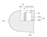
- FIG. 2 is a cross-sectional view of the rim and left spoke along line II-II extending radially in Figure 1;
- Fig. 3 is an exploded perspective view of the left accessory operating console unit and the left electrode device;
- FIG. 4 is a diagram schematically showing the range of electric lines of force induced around electrode devices provided on each spoke by applying a predetermined voltage to the electrode devices. It is a figure showing composition of a steering device concerning a 2nd embodiment of the present invention.
- FIG. 1 is a diagram showing the configuration of a steering device 1 according to this embodiment.
- the steering device 1 includes a steering handle 2 that receives a driver's steering operation of the vehicle and operation of vehicle accessories, a steering shaft 3 that supports the steering handle 2 , and a steering control device 4 .
- the steering handle 2 has an annular rim portion 20 that can be gripped by the driver, a hub portion 23 provided inside the rim portion 20, and a rim portion extending from the hub portion 23 along the radial direction of the rim portion 20. and three spoke portions 25L, 25R, 25D connected to the inner rim portion 21 of the portion 20.
- the hub portion 23 is disc-shaped, for example, provided at the center of the rim portion 20 as seen from the driver, and constitutes the center of the steering handle 2 .
- the steering shaft 3 is also provided with a torque sensor 31 that detects steering torque acting on the steering shaft 3 and outputs a signal corresponding to the detected value to the steering control device 4 .
- the rim portion 20 and hub portion 23 are connected by three spoke portions 25L, 25R and 25D.
- the left spoke portion 25L extends in the horizontal direction and connects the left portion of the hub portion 23 as seen from the driver and the left portion of the rim inner peripheral portion 21 as seen from the driver.
- the right spoke portion 25R extends in parallel with the left spoke portion 25L and along the horizontal direction, and extends between the right portion of the hub portion 23 as seen from the driver and the right portion of the rim inner peripheral portion 21 as seen from the driver. to connect.
- the lower spoke portion 25D extends perpendicularly to the spoke portions 25L and 25R along the vertical direction, and is positioned below the hub portion 23 as seen from the driver and below the rim inner peripheral portion 21 as seen from the driver. Connect the side parts.
- the rim portion 20 is represented by a clockwise angle [°] with respect to the upper end portion 20C of the rim portion 20 as seen from the driver. That is, the right spoke portion 25R extends along the 90° direction and connects the hub portion 23 and the rim inner peripheral portion 21 at 90°.
- the lower spoke portion 25D extends along the 180° direction and connects the hub portion 23 and the 180° portion of the rim inner peripheral portion 21 .
- the left spoke portion 25L extends along the 270° direction and connects the hub portion 23 and the 270° portion of the rim inner peripheral portion 21 .
- the left spoke portion 25L and the right spoke portion 25R are respectively provided with left auxiliary machine operation signals for receiving auxiliary machine operation by the driver for operating vehicle auxiliary machines (for example, an audio system, a car navigation system, etc.) not shown by the driver.
- a console unit 5L, a right accessory operation console unit 5R, and a left electrode device 6L and a right electrode device 6R for detecting a driver's hand touching or approaching the steering wheel 2 are provided.
- These accessory operating console units 5L and 5R are each rectangular when viewed from the driver.
- a driver can operate vehicle accessories by operating a plurality of switches 51L, 52L, 53L, 51R, 52R, and 53R provided on these accessory operation console units 5L and 5R with a finger. ing.
- FIG. 2 is a cross-sectional view of the rim portion 20 and the left spoke portion 25L along line II-II extending radially in FIG.
- a left spoke connection portion 22L which is a portion of the rim inner peripheral portion 21 to which the left spoke portion 25L is connected, is concave when viewed from the driver's side (that is, the upper side in FIG. 2).
- the right spoke connection portion 22R which is the portion of the rim inner peripheral portion 21 to which the right spoke portion 25R is connected, is similarly concave when viewed from the driver's side.
- FIG. 3 is an exploded perspective view of the left accessory operating console unit 5L and the left electrode device 6L.
- the left accessory operation console unit 5L includes a plurality of lid-like switches 51L, 52L, 53L for receiving accessory operation by the driver, and a console main body 50L supporting these switches 51L, 52L, 53L.
- the console main body 50L is columnar and rectangular when viewed from the driver.
- the plurality of switches 51L, 52L, 53L are each lid-shaped and attached to the upper surface 501L of the console main body 50L on the driver side.
- the left electrode device 6L includes a first electrode portion 61L provided around the side wall surfaces 502L and 503L of the console body 50L, and a second electrode portion 62L provided on the rear surface 505L side of the console body 50L as seen from the driver. Prepare.
- the first electrode portion 61L is formed by bending a conductive plate material and has an L shape when viewed from the driver. More specifically, the first electrode portion 61L includes a first flat portion 611L extending along the first side wall surface 502L on the upper side of the console body 50L as seen from the driver, and a first flat portion 611L of the console body 50L extending along the upper side of the console body 50L as seen from the driver. and a second flat portion 612L extending along the second side wall surface 503L on the left side (that is, the radially outer side of the rim portion 20) and having an arc shape when viewed from the driver.
- the first electrode portion 61L has a first flat portion 611L along the first side wall surface 502L, and a second flat portion 612L facing the second side wall surface 503L and radially outward from the second side wall surface 503L. It is attached to the left spoke portion 25L and the left spoke connection portion 22L together with the console body 50L so as to be provided at a slightly distant position. As a result, as shown in FIGS. 1 and 2 , the first electrode portion 61L faces the radially outer plane of the first flat portion 611L toward the rim inner peripheral portion 21 and the radially outer plane of the second flat portion 612L. oriented radially outward at the left spoke portion 25L and the left spoke connection portion 22L.
- the portion of the first electrode portion 61L that is farthest from the hub portion 23 in the radial direction A certain outermost diameter portion 613L is in contact with both the contour line of the rim inner peripheral portion 21 above the left spoke portion 25L and the contour line of the rim inner peripheral portion 21 below the left spoke portion 25L as viewed from the driver. It is arranged radially outward from the arcuate imaginary line L1.
- the end portion on the lower side as seen from the driver is branched in a Y shape, and the lower portion of the left spoke portion 25L and the rim are separated from the lower side of the left spoke portion 25L as seen from the driver. It has a plane 614L facing the space between it and the inner peripheral portion 21 .
- the second electrode portion 62L is the same conductive plate material as the first electrode portion 61L, and is provided on the rear surface 505L side of the console main body 50L as seen from the driver. Therefore, the surface 620L of the second electrode portion 62L faces the direction perpendicular to the first electrode portion 61L, that is, faces the driver when the second electrode portion 62L is provided on the left spoke portion 25L together with the console body 50L.
- the detailed configurations of the left accessory operating console unit 5L and the left electrode device 6L have been described above with reference to FIGS.
- the detailed configurations of the right auxiliary machine operating console unit 5R and the right electrode device 6R are substantially the same as the left auxiliary machine operating console 5L and the left electrode device 6L except for their arrangement positions and orientations. Differences from the operation console unit 5L and the left electrode device 6L will be mainly described, and illustrations and detailed descriptions of the same points as the left accessory operation console unit 5L and the left electrode device 6L will be omitted as appropriate.
- the right accessory operation console unit 5R includes a plurality of lid-like switches 51R, 52R, and 53R for receiving accessory operation by the driver, and a column-like console body (not shown) that supports these switches 51R, 52R, and 53R. , provided.
- the right electrode device 6R includes a first electrode portion 61R provided around the side wall surface of the console main body, and a second electrode portion (not shown) provided on the rear side of the console main body as seen from the driver.
- the first electrode portion 61R is formed by bending a conductive plate material and has an L shape when viewed from the driver. More specifically, the first electrode portion 61R includes a first flat portion 611R extending along the first side wall surface on the upper side of the console main body as seen from the driver, and a right side of the console main body as seen from the driver ( That is, the second plane portion 612R extends along the second side wall surface (outside in the radial direction of the rim portion 20) and has an arc shape when viewed from the driver.
- the first electrode portion 61R has a first flat portion 611R along the first side wall surface of the console main body, and a second flat portion 612R facing the second side wall surface of the console main body and extending radially from the second side wall surface. It is attached to the right spoke portion 25R and the right spoke connection portion 22R together with the console body so as to be provided at a position slightly spaced outward in the direction. As a result, as shown in FIG. 1, the first electrode portion 61R faces the radial outer plane of the first flat portion 611R toward the rim inner peripheral portion 21, and the radial outer plane of the second flat portion 612L faces the radial direction. It is provided on the right spoke portion 25R and the right spoke connection portion 22R while facing outward.
- the farthest portion of the first electrode portion 61R from the hub portion 23 along the radial direction A certain outermost diameter portion 613R is in contact with both the contour line of the rim inner peripheral portion 21 above the right spoke portion 25R and the contour line of the rim inner peripheral portion 21 below the right spoke portion 25R when viewed from the driver. It is arranged radially outward from the arcuate imaginary line L2.
- the end portion on the lower side as seen from the driver is branched in a Y shape, and the lower side and the rim of the right spoke portion 25R as seen from the driver. It has a plane 614R facing the space between it and the inner periphery 21 .
- the second electrode portion of the right electrode device 6R is made of the same conductive plate material as the first electrode portion 61R, and is provided on the rear side of the console main body as seen from the driver. Therefore, the surface of the second electrode portion faces the direction perpendicular to the first electrode portion 61R, that is, faces the driver when the second electrode portion is provided on the right spoke portion 25R together with the console body.
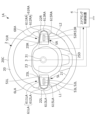
- FIG. 4 is a diagram schematically showing ranges RL and RR of lines of electric force induced around the electrode devices 6L and 6R by applying a predetermined voltage to the electrode devices 6L and 6R as described above. be.
- the first electrode portions 61L, 61R of the respective electrode devices 6L, 6R are provided with the first flat portions 611L, 611R and the second flat portions 612L, 612R facing radially outward. Therefore, the first flat portion 611L of the rim portion 20 is within the range RL, RR of the lines of electric force induced around the electrode devices 6L, 6R by applying a voltage to the electrode devices 6L, 6R. , 611R and the second planar portions 612L, 612R are oriented from 270° to 300° and from 60° to 90°.
- the second flat portions 612L, 612R are provided at the spoke connection portions 22L, 22R closer to the rim portion 20 than the spoke portions 25L, 25R. More specifically, outermost diameter portions 613L and 613R of the second flat portions 612L and 612R, which are the farthest in the radial direction from the hub portion 23, are arranged radially outside of the virtual lines L1 and L2. Therefore, of the ranges RL and RR of the electric lines of force induced around these electrode devices 6L and 6R, the portions near 270° and 90° extend farther along the radial direction than the other portions. Electric lines of force can be induced.
- the planes 614L, 614R of the rim portion 20 are within the ranges RL, RR of the lines of electric force induced around the electrode devices 6L, 6R by applying a voltage to the electrode devices 6L, 6R. Includes oriented 240°-270° and 90°-120° ranges.
- the steering control device 4 detects changes in capacitance between the electrode devices 6L, 6R and the ground, and detects changes in capacitance between the electrode devices 6L, 6R and the torque sensor 31. Whether or not the driver is holding the steering wheel 2 is determined based on the detected steering torque.
- the steering control device 4 detects when the steering torque detected by the torque sensor 31 is greater than or equal to a predetermined torque threshold set near 0, or when the capacitance of either the electrode device 6L or 6R is greater than or equal to a predetermined capacitance threshold value, it is determined that the driver is gripping the steering wheel 2, the steering torque is less than the torque threshold value, and the electrode device 6L, If the width of change in both capacitances of 6R is less than the capacitance threshold, it is determined that the driver is not gripping the steering wheel 2 .
- the driver may hold the steering handle 2 with both hands on the 90° and 270° portions of the rim portion 20. many.
- the steering torque may be less than the torque threshold even though the driver is gripping the steering wheel 2 . Therefore, it is not possible to appropriately determine whether or not the driver is gripping the steering wheel 2 based only on the detection signal of the torque sensor 31 .
- the steering control device 4 controls the grip of the steering wheel 2 by the driver based on the detection signal of the torque sensor 31 and changes in the capacitance of the two electrode devices 6L and 6R as described above. By determining whether or not the driver is gripping the steering handle 2, it is possible to accurately determine whether or not the driver is gripping the steering wheel 2 even in a situation where it is difficult for the torque sensor 31 to detect.
- the steering device 1 has the following effects.
- the steering device 1 includes a steering handle 2 having a rim portion 20, a hub portion 23, and spoke portions 25L and 25R, electrode devices 6L and 6R provided on the steering handle 2, and these electrode devices 6L and 6R. and a steering control device 4 that detects a change in the capacitance of.
- the electrode devices 4L and 4R are provided with the first electrode portions 61L and 61R provided at the spoke connection portions 22L and 22R of the rim inner peripheral portion 21 to which the spoke portions 25L and 25R are connected.
- the first electrode portions 61L and 61R provided on the spoke connection portions 22L and 22R closer to the rim portion 20 than the spoke portions 25L and 25R cause the spoke connection portion 22L of the rim portion 20 in particular. , 22R, it is possible to detect the driver's hand in contact with or in close proximity to the rim 20 with higher accuracy than in the prior art in which electrodes are provided on the spokes 25L, 25R. It can improve traffic safety.
- the outermost diameter portions 613L and 613R which are the farthest portions in the radial direction from the hub portion 23 of the first electrode portions 61L and 61R, are located near the spoke portions 25L and 25R when viewed from the driver. It is arranged radially outside of arcuate imaginary lines L1 and L2 that contact both the contour of the inner rim portion 21 above and the contour of the inner rim portion 21 below the spokes 25L and 25R.
- the portion of the rim portion 20 radially outside the spoke connection portions 22L and 22R more specifically, the portion near 90° that can be gripped by the driver's right hand and the driver's left hand can be gripped. Since many electric lines of force can be induced in the portions near 270°, the driver's hands in contact with or close to these portions can be accurately detected, and traffic safety can be improved.
- the portions including the outermost diameter portions 613L and 613R of the first electrode portions 61L and 61R are arcuate along the rim portion 20 when viewed from the driver and directed radially outward. has a flat surface. Therefore, in the steering device 1, the portion of the rim portion 20 that is radially outward of the spoke connection portions 22L and 22R, more specifically, the portion near 90° that can be gripped by the driver's right hand and the driver's left hand. Since more electric lines of force can be induced in the parts near 270° that can be grasped, the driver's hand touching or close to these parts can be detected with higher accuracy, and traffic safety is improved. can do.
- the first electrode portions 61L and 61R are L-shaped when viewed from the driver, and are arranged on the upper first side wall surfaces of the accessory operating console units 5L and 5R when viewed from the driver.
- a first flat portion 611L having a flat surface facing toward the rim inner peripheral portion 21 and a second side wall surface of the accessory operation console units 5L and 5R radially outward from the driver.
- second flat portions 612L and 612R provided at positions spaced outward. Therefore, in the steering device 1, of the annular rim portion 20, a portion in the range of 60° to 90° that can be gripped by the driver's right hand and a portion in the range of 270° to 300° that can be gripped by the driver's left hand. Since many electric lines of force can be induced in the vicinity of the rim portion 20, it is possible to accurately detect the hand of the driver coming into contact with or close to the range of the rim portion 20, and thus traffic safety can be improved. can.
- the lower end portions of the second flat portions 612L and 612R as seen from the driver are Y-shaped as seen from the driver, and the lower portions of the spoke portions 25L and 25R and the rim It has planes 614L, 614R directed to the space between the inner peripheral portion 21.
- electric lines of force can be induced that pass through the rim portion 20 below the spoke portions 25L and 25R, so that the driver's hand in contact with or close to the rim portion 20 can be detected with high accuracy. It can improve traffic safety.
- the second electrode portion having a flat surface facing the driver is provided on the back side of the accessory operating console units 5L and 5R.
- FIG. 5 is a diagram showing the configuration of the steering device 1A according to this embodiment.
- the steering device 1A differs from the steering device 1 according to the first embodiment in the configurations of the electrode devices 6LA and 6RA provided on the spoke portions 25L and 25R and the spoke connection portions 22L and 22R. More specifically, the steering device 1A differs from the steering device 1 according to the first embodiment in the configuration of the first electrode portions 61LA and 61RA of the electrode devices 6LA and 6RA.
- the first electrode portions 61LA and 61RA provided on the spoke portions 25L and 25R are C-shaped when viewed from the driver. That is, each of the first electrode portions 61LA and 61RA has a flat surface facing the rim inner peripheral portion 21 along the upper first side wall surface of the accessory operation console units 5L and 5R as viewed from the driver.
- First flat portions 611LA and 611RA, and second flat portions 612LA provided at positions spaced radially outward from the second side wall surfaces of the accessory operation console units 5L and 5R, which are radially outward as viewed from the driver.
- 612RA, and third plane portions 615LA and 615RA which are provided along the third side wall surface on the lower side of the accessory operating console units 5L and 5R as seen from the driver and have a plane facing the rim inner peripheral portion 21. , provided.
- the second flat portions 612LA and 612RA are arcuate when viewed from the driver.
- Outermost diameter portions 613LA and 613RA, which are the farthest portions from the hub portion 23 in the radial direction, of the second flat portions 612LA and 612RA are arranged radially outside of the virtual lines L1 and L2.
- the steering device 1A has the following effects.
- the first electrode portions 61LA and 61RA are C-shaped when viewed from the driver, and are arranged on the upper first side wall surfaces of the accessory operation console units 5L and 5R when viewed from the driver.
- First plane portions 611LA and 611RA having planes provided along and facing the rim inner peripheral portion 21, and second side wall surfaces of the accessory operation console units 5L and 5R that are radially outward from the driver's side.
- Second flat portions 612LA and 612RA provided at positions spaced radially outward, and auxiliary machine operation console units 5L and 5R provided along the lower third side wall surface as seen from the driver and inside the rim.
- left electrode device (electrode device) 61L, 61LA first electrode portion 611L, 611LA first plane portion 612L, 612LA second plane portion 613L, 613LA outermost diameter portion 614L plane 615LA third plane portion 62L second electrode portion 5R right Auxiliary equipment operation console unit (Auxiliary equipment operation console) 6R, 6RA...Right electrode device (electrode device) 61R, 61RA first electrode portion 611R, 611RA first plane portion 612R, 612RA second plane portion 613R, 613RA outermost diameter portion 614R plane 615RA third plane portion
Landscapes
- Engineering & Computer Science (AREA)
- Chemical & Material Sciences (AREA)
- Combustion & Propulsion (AREA)
- Transportation (AREA)
- Mechanical Engineering (AREA)
- Steering Controls (AREA)
Abstract
Description
以下、本発明の第1実施形態に係るステアリング装置について、図面を参照しながら説明する。
左補機操作コンソールユニット5Lは、運転者による補機操作を受け付ける複数の蓋状のスイッチ51L,52L,53Lと、これらスイッチ51L,52L,53Lを支持するコンソール本体50Lと、を備える。
(1)ステアリング装置1は、リム部20、ハブ部23、及びスポーク部25L,25Rを備えるステアリングハンドル2と、このステアリングハンドル2に設けられた電極装置6L,6Rと、これら電極装置6L,6Rの静電容量の変化を検出するステアリング制御装置4と、を備える。またステアリング装置1では、電極装置4L,4Rは、リム内周部21のうちスポーク部25L,25Rが接続されるスポーク接続部22L,22Rに設けられた第1電極部61L,61Rを備える。よってステアリング装置1によれば、スポーク部25L,25Rよりもよりリム部20に近いスポーク接続部22L,22Rに設けられた第1電極部61L,61Rによって、リム部20のうち特にスポーク接続部22L,22Rの近傍を通過する電気力線を誘起することができるので、スポーク部25L,25Rに電極を設ける従来と比較して、リム部20と接触又は近接する運転者の手を精度良く検出することができ、ひいては交通の安全性を向上することができる。
次に、本発明の第2実施形態に係るステアリング装置について、図面を参照しながら説明する。なお以下の説明において、第1実施形態に係るステアリング装置と同じ構成については、同じ符号を付し詳細な説明を省略する。
(7)ステアリング装置1Aにおいて、第1電極部61LA,61RAは、運転者から視てC字状であり、補機操作コンソールユニット5L,5Rのうち運転者から視て上側の第1側壁面に沿って設けられかつリム内周部21へ向けられた平面を有する第1平面部611LA,611RAと、補機操作コンソールユニット5L,5Rのうち運転者から視て径方向外側の第2側壁面から径方向外側へ離れた位置に設けられた第2平面部612LA,612RAと、補機操作コンソールユニット5L,5Rのうち運転者から視て下側の第3側壁面に沿って設けられかつリム内周部21へ向けられた平面を有する第3平面部615LA,615RAと、を備える。よってステアリング装置1Aでは、円環状のリム部20のうち、運転者の右手が把持し得る60°~120°の範囲の部分及び運転者の左手が把持し得る240°~300°の範囲の部分の近傍に多くの電気力線を誘起することができるので、これらリム部20の範囲と接触又は近接する運転者の手を精度良く検出することができ、ひいては交通の安全性を向上することができる。
2…ステアリングハンドル
20…リム部
21…リム内周部
22L…左スポーク接続部(接続部)
22R…右スポーク接続部(接続部)
23…ハブ部
25L…左スポーク部
25R…右スポーク部
3…ステアリングシャフト
4…ステアリング制御装置(制御部)
5L…左補機操作コンソールユニット(補機操作コンソール)
6L,6LA…左電極装置(電極装置)
61L,61LA…第1電極部
611L,611LA…第1平面部
612L,612LA…第2平面部
613L,613LA…最外径部
614L…平面
615LA…第3平面部
62L…第2電極部
5R…右補機操作コンソールユニット(補機操作コンソール)
6R,6RA…右電極装置(電極装置)
61R,61RA…第1電極部
611R,611RA…第1平面部
612R,612RA…第2平面部
613R,613RA…最外径部
614R…平面
615RA…第3平面部
Claims (7)
- 運転者による操舵操作を受け付けるステアリング装置であって、
環状のリム部、前記リム部の内側に設けられたハブ部、及び前記リム部の径方向に沿って延び前記ハブ部と前記リム部のリム内周部とを接続するスポーク部を備えるステアリングハンドルと、
前記ステアリングハンドルに設けられた電極装置と、
前記電極装置の静電容量の変化を検出する制御部と、を備え、
前記電極装置は、前記リム内周部のうち前記スポーク部が接続される接続部に設けられた第1電極部を備えることを特徴とするステアリング装置。 - 前記第1電極部のうち前記ハブ部から前記径方向に沿って最も遠い部分である最外径部は、運転者から視て前記スポーク部より上側の前記リム内周部の輪郭線と前記スポーク部より下側の前記リム内周部の輪郭線とに接する円弧状の仮想線より前記径方向に外側に配置されていることを特徴とする請求項1に記載のステアリング装置。
- 前記第1電極部のうち前記最外径部を含む部分は、運転者から視て弧状であり、前記径方向に外側に向けられた平面を有することを特徴とする請求項2に記載のステアリング装置。
- 前記スポーク部には、運転者による補機操作を受け付けかつ運転者から視て矩形状の補機操作コンソールが設けられ、
前記第1電極部は、運転者から視てL字状であり、前記補機操作コンソールのうち運転者から視て上側の第1側壁面に沿って設けられ前記リム内周部へ向けられた平面を有する第1平面部と、前記補機操作コンソールのうち運転者から視て前記径方向の外側の第2側壁面から前記径方向の外側へ離れた位置に設けられた第2平面部と、を備えることを特徴とする請求項1から3の何れかに記載のステアリング装置。 - 前記第2平面部のうち運転者から視て下側の端部はY字状であり、運転者から視て前記スポーク部の下側と前記リム内周部との間の空間に向けられた平面を有することを特徴とする請求項4に記載のステアリング装置。
- 前記スポーク部には、運転者による補機操作を受け付けかつ運転者から視て矩形状の補機操作コンソールが設けられ、
前記第1電極部は、運転者から視てC字状であり、前記補機操作コンソールのうち運転者から視て上側の第1側壁面に沿って設けられ前記リム内周部へ向けられた平面を有する第1平面部と、前記補機操作コンソールのうち運転者から視て前記径方向の外側の第2側壁面から前記径方向の外側へ離れた位置に設けられた第2平面部と、前記補機操作コンソールのうち運転者から視て下側の第3側壁面に沿って設けられ前記リム内周部へ向けられた平面を有する第3平面部と、を備えることを特徴とする請求項1から3の何れかに記載のステアリング装置。 - 前記電極装置は、前記補機操作コンソールの背面側に設けられかつ運転者へ向けられた平面を有する第2電極部をさらに備えることを特徴とする請求項4から6の何れかに記載のステアリング装置。
Priority Applications (3)
| Application Number | Priority Date | Filing Date | Title |
|---|---|---|---|
| CN202280089190.1A CN118574761A (zh) | 2022-01-17 | 2022-01-17 | 转向装置 |
| PCT/JP2022/001394 WO2023135806A1 (ja) | 2022-01-17 | 2022-01-17 | ステアリング装置 |
| JP2023573802A JPWO2023135806A1 (ja) | 2022-01-17 | 2022-01-17 |
Applications Claiming Priority (1)
| Application Number | Priority Date | Filing Date | Title |
|---|---|---|---|
| PCT/JP2022/001394 WO2023135806A1 (ja) | 2022-01-17 | 2022-01-17 | ステアリング装置 |
Publications (1)
| Publication Number | Publication Date |
|---|---|
| WO2023135806A1 true WO2023135806A1 (ja) | 2023-07-20 |
Family
ID=87278663
Family Applications (1)
| Application Number | Title | Priority Date | Filing Date |
|---|---|---|---|
| PCT/JP2022/001394 WO2023135806A1 (ja) | 2022-01-17 | 2022-01-17 | ステアリング装置 |
Country Status (3)
| Country | Link |
|---|---|
| JP (1) | JPWO2023135806A1 (ja) |
| CN (1) | CN118574761A (ja) |
| WO (1) | WO2023135806A1 (ja) |
Citations (5)
| Publication number | Priority date | Publication date | Assignee | Title |
|---|---|---|---|---|
| JP2002085360A (ja) * | 2000-09-14 | 2002-03-26 | Isuzu Motors Ltd | 心拍信号検出装置 |
| JP2008237378A (ja) * | 2007-03-26 | 2008-10-09 | Denso Corp | 生体信号検出装置 |
| WO2016013180A1 (ja) * | 2014-07-23 | 2016-01-28 | パナソニックIpマネジメント株式会社 | ヒータ装置、ステアリングホイール、および運輸装置 |
| WO2020195620A1 (ja) * | 2019-03-25 | 2020-10-01 | アルプスアルパイン株式会社 | センサ装置及びステアリングホイール |
| CN112249146A (zh) * | 2020-11-10 | 2021-01-22 | 锦州锦恒汽车安全系统股份有限公司 | 一种离手检测方向盘 |
-
2022
- 2022-01-17 JP JP2023573802A patent/JPWO2023135806A1/ja active Pending
- 2022-01-17 CN CN202280089190.1A patent/CN118574761A/zh active Pending
- 2022-01-17 WO PCT/JP2022/001394 patent/WO2023135806A1/ja active Application Filing
Patent Citations (5)
| Publication number | Priority date | Publication date | Assignee | Title |
|---|---|---|---|---|
| JP2002085360A (ja) * | 2000-09-14 | 2002-03-26 | Isuzu Motors Ltd | 心拍信号検出装置 |
| JP2008237378A (ja) * | 2007-03-26 | 2008-10-09 | Denso Corp | 生体信号検出装置 |
| WO2016013180A1 (ja) * | 2014-07-23 | 2016-01-28 | パナソニックIpマネジメント株式会社 | ヒータ装置、ステアリングホイール、および運輸装置 |
| WO2020195620A1 (ja) * | 2019-03-25 | 2020-10-01 | アルプスアルパイン株式会社 | センサ装置及びステアリングホイール |
| CN112249146A (zh) * | 2020-11-10 | 2021-01-22 | 锦州锦恒汽车安全系统股份有限公司 | 一种离手检测方向盘 |
Also Published As
| Publication number | Publication date |
|---|---|
| JPWO2023135806A1 (ja) | 2023-07-20 |
| CN118574761A (zh) | 2024-08-30 |
Similar Documents
| Publication | Publication Date | Title |
|---|---|---|
| JP4724646B2 (ja) | 自動二輪車の車輪速センサ取付構造 | |
| KR101539027B1 (ko) | 인휠모터 구동 자동차의 조향장치 및 이를 이용한 조향 제어방법 | |
| KR102568446B1 (ko) | 전방 인식 시스템을 위한 처리 유닛 및 처리 방법, 전방 인식 시스템, 및, 모터사이클 | |
| WO2018198536A1 (ja) | 駐車支援装置 | |
| WO2023135806A1 (ja) | ステアリング装置 | |
| CN111284558A (zh) | 用于控制车辆转弯的系统和方法 | |
| JP6655711B2 (ja) | ステアリング装置 | |
| JP7125926B2 (ja) | 車両制御システム | |
| JP7627789B2 (ja) | ステアリング装置 | |
| JP2021178590A (ja) | タイヤ取付け位置検出システム、タイヤ及びタイヤ用センサユニット | |
| US20250065941A1 (en) | Steering device | |
| JP2014004932A (ja) | 駐車支援装置、駐車支援方法、およびプログラム | |
| US20250065942A1 (en) | Steering device | |
| JP7503703B2 (ja) | 支援装置および鞍乗型車両 | |
| JP7577103B2 (ja) | ステアリング装置 | |
| TW202246106A (zh) | 把手開關及跨坐型車輛 | |
| JP7477585B1 (ja) | ステアリング装置 | |
| JP2017116274A (ja) | 車両の操舵角加速度検出装置 | |
| WO2024048533A1 (ja) | リーン車両 | |
| JP2019166978A (ja) | ステアリング装置 | |
| JP2023104270A (ja) | 把持検出装置 | |
| JPH11227625A (ja) | 全方向移動車両の操舵装置 | |
| JP2007308038A (ja) | 車両の操舵角度検出装置 | |
| JP2004135428A (ja) | 電気式産業車両の走行制御装置及び走行制御方法 | |
| TW202417311A (zh) | 傾斜車輛 |
Legal Events
| Date | Code | Title | Description |
|---|---|---|---|
| 121 | Ep: the epo has been informed by wipo that ep was designated in this application |
Ref document number: 22920331 Country of ref document: EP Kind code of ref document: A1 |
|
| ENP | Entry into the national phase |
Ref document number: 2023573802 Country of ref document: JP Kind code of ref document: A |
|
| WWE | Wipo information: entry into national phase |
Ref document number: 18729512 Country of ref document: US Ref document number: 202280089190.1 Country of ref document: CN |
|
| NENP | Non-entry into the national phase |
Ref country code: DE |
|
| 122 | Ep: pct application non-entry in european phase |
Ref document number: 22920331 Country of ref document: EP Kind code of ref document: A1 |